Article

Risk Based Maintenance in the Hydroelectric Power Plants

Department of Industrial Engineering, Faculty of Engineering, Kırıkkale University, 71450 Kırıkkale, Turkey
*
Author to whom correspondence should be addressed.
Energies 2019, 12(8), 1502; https://doi.org/10.3390/en12081502
Submission received: 21 March 2019 / Revised: 16 April 2019 / Accepted: 17 April 2019 / Published: 20 April 2019
(This article belongs to the Special Issue Electric Power Systems Research 2019)

Abstract

:
In this study, maintenance planning problem is handled in one of the hydroelectric power plants which directly affect Turkey’s energy supply security with a fifth share in the total generation. In this study, a result is obtained by taking into consideration the multi-objective and multi-criteria structure of the maintenance planning in the hydroelectric power plants with thousands of complex equipment and the direct effect of this equipment on uninterrupted and low-cost electricity generation. In the first stage, the risk levels of the equipment in terms of the power plant are obtained with the combination of AHP (Analytical Hierarchy Process) and TOPSIS (technique for order preference by similarity to ideal solution) which are frequently used in the literature due to their advantages. Department-based maintenance plans of all equipment for periodic and revision maintenance strategies are formed by integrating these values into the time allocated for maintenance and the number of employees constraints. As a result of the application of this methodology which is designed for the first time in the literature with the integration of multi-criteria decision-making methods for the maintenance planning problem in a hydroelectric power plant, all elements that prevent the sustainable energy supply in the power plant are eliminated.

1. Introduction

Electricity generation plants are large-scale infrastructure investments with a comprehensive goal of sustainable energy supply. The broad scope of this aim is to realize uninterruptedly, reliably, efficiently, economically and environmentally sensitive electricity production simultaneously. In this facility, in the process of using economic life at the highest possible level without departing from the sustainability perspective, the operation of the facilities in accordance with the operating directives given by the manufacturing companies and the rational application of the two main pillars. In other words, conducting appropriate maintenance processes in electricity generation plants simultaneously with appropriate operation rules is of great importance for sustainable energy supply [1]. Maintenance is referred to as a set of technical actions to ensure that a machine or equipment is fully functional in its economic life [2]. The main purpose of maintenance activities is to maximize productivity and efficiency level of production and increase reliability. This goal makes maintenance one of the main processes for the production to reach a specific efficiency and effectiveness goal [3]. In the case of continuous production systems such as electricity generation facilities where this work is carried out, the cost of production loss, which is the result of production stops due to faults, and the time required for maintenance, manpower and material requirements, is a process with a high cost of maintenance. In this context, it is necessary to manage the critical energy maintenance in a system in order to achieve the sustainable energy supply target in electricity generation plants and the most critical phase of the maintenance management system, which has a great impact on the social welfare, constitutes the maintenance planning. The maintenance of all the equipment in the electricity generation plants of thousands of equipment is not a rational approach as mentioned above due to production stops and all other costs associated with maintenance. However, in terms of the criticality of equipment plant (risk) levels of planning to make a plan of maintenance according to their importance in terms of taking into account plant equipment is versatile and a policy that also coincides with the multi-criteria structure. Within the scope in this study Turkey accounts for approximately 70% of segments [4] of the renewable energy power board and the high capacity October 2018 end of Turkey’s total power generation of the primary maintenance in one of the large scale of the hydroelectric power plants [5] that performs 20% of equipment to operate in the power plant’s maximum efficiency in terms of the risks it carries out, manpower and maintenance planning were made. In the first stage, the criteria affecting the risk levels of the equipment in the plant in terms of power plant, 10 to 25 years with hydroelectric power plant operation and maintenance experience, industry, electricity, electrical-electronics and mechanical engineer with eight power plant experts considering the real-life hydroelectric power plant operation rules and weighted by AHP method which is frequently used in literature. Critical levels of equipment were determined by using one of the leading TOPSIS methods with ease of application and significant results. In the second stage, three alternative scenarios are produced based on the characteristics of the equipment and the characteristics of the equipment that affect the maintenance of the equipment and the efficient operation of the plant and according to these scenarios, all equipment with high risk levels for the power plant are distributed to those who are eligible for revision maintenance strategies that can be defined as periodic and comprehensive periodic maintenance up to 4-year period, maintenance and workforce plans were established on the basis of electrical and machinery maintenance services where equipment was grouped according to specifications within the power plant. The planned maintenance plans were operated for 2 years and as a result of these efforts for the sustainable energy supply of the power plant, a 100% improvement was achieved in the production stops due to the failure to manage the maintenance in a system. In the second part of the study, operation and maintenance principles of hydroelectric power plants are summarized. In the third chapter, reference to risk-based maintenance planning studies in the literature and in the fourth chapter, the methods used in the application are explained with their reasons, the details of the application are given in the fifth chapter. The study was completed by presenting the results obtained in the sixth and last part of the study and suggestions for future studies.

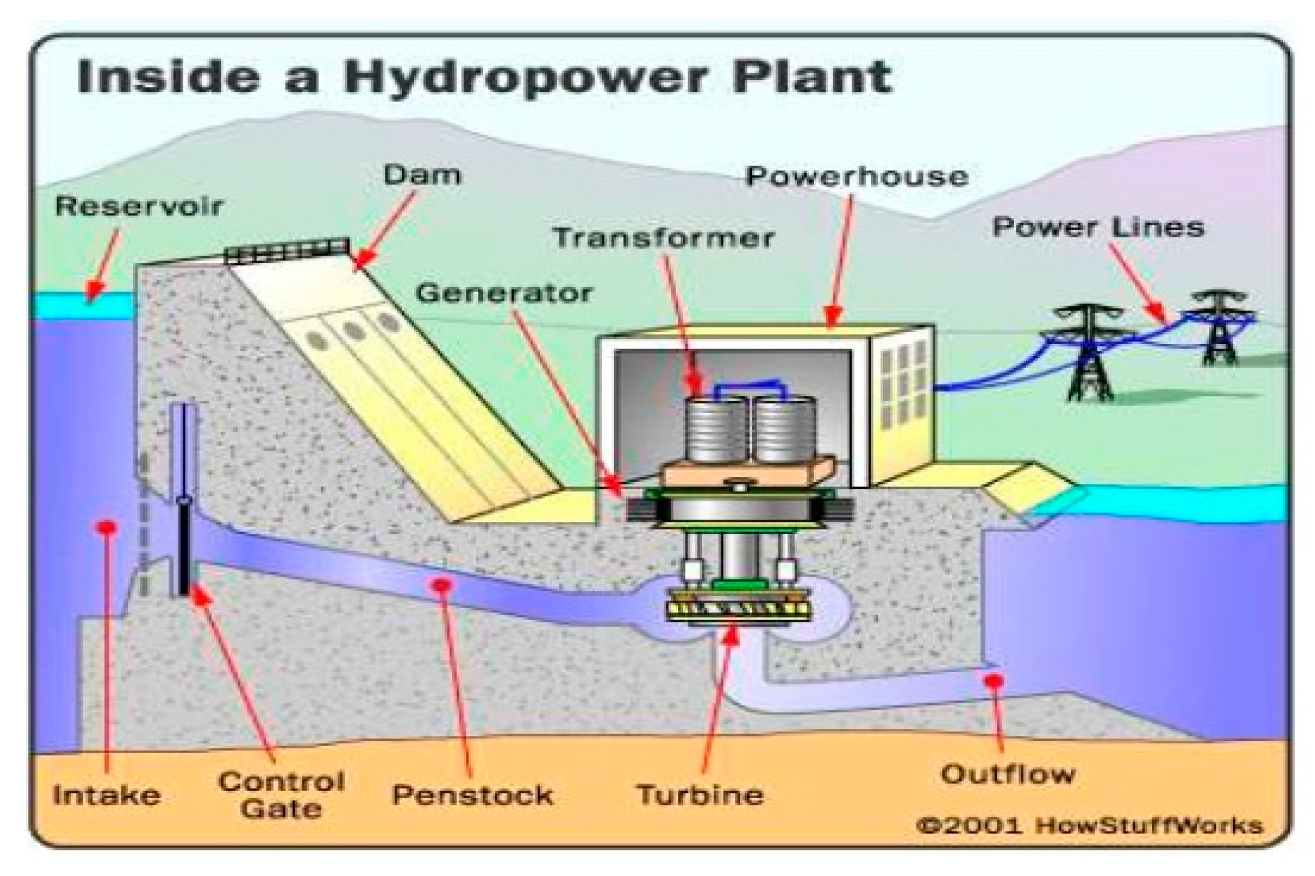
2. Operating and Maintenance Principles of Hydroelectric Power Facilities

The use of renewable resources in the production of electrical energy has been continuously increasing worldwide. Renewable energy sources can be considered rich in Turkey in terms of installed power in the first place in terms of hydraulic resources [4]. Hydraulic power that uses one of the most mature technologies in renewable resources, it is the most consistent and most flexible renewable energy source in terms of meeting the peak and unexpected power demands, as well as meeting the basic load electricity needs. By the end of January 2019 the total installed capacity reached 89,132.0 MW in Turkey, 31.74% share (28,291.4 MW) hydroelectric power facilities are located in the first [5]. In this context, as in the world energy mix, hydroelectric power facilities are of critical importance for the Turkish electricity generation sector and in this study, a large scale of hydroelectric power plants that will contribute to the country’s economy and social welfare are selected as application areas provided that sustainability is ensured. Kinetic energy is seen in the sea with water energy, rivers, flowing sea gorges and tidal events, natural lakes in high mountains and highlands and potential energy in dams. Depending on the location of the water, this energy (kinetic or potential energy—the potential of water in the dam body or natural lakes is converted into kinetic energy in transmission tunnels such as penstock) is converted to mechanical energy by turning the turbine shaft of the water that hits the turbine wheel in hydroelectric power facilities. The turbine shaft is connected directly or by a gear system to the generator rotor. When the windings on the generator rotor are externally excited by a direct current power supply, a magnetic field is generated around the rotor. This magnetic field is formed around the rotating rotor to induce electric energy by induction in the stator windings. The electrical energy obtained is connected to the interconnected system with the power transmission lines [6] (Figure 1).
As in all power facilities, the main purpose of hydroelectric power facilities is to produce electricity that is uninterrupted, reliable, efficient, economical and environmentally friendly, also called sustainable energy supply. The first step in the realization of this objective is the operation of the facilities in accordance with the operational directives determined by the machinery/equipment/system manufacturer organizations. Implementation of these operational rules in a hydroelectric power plant is not sufficient alone for sustainable energy generation. Due to the changes in temperature and pressure, the fatigue due to the operation of the equipment for many years, the changes in the atmospheric conditions and the topographic conditions, such as maintenance and/or repair of every equipment in the plant may be required. Therefore, the second phase in realizing the objective of sustainable power generation in hydroelectric power facilities is to implement planned maintenance schedules based on the current situation and characteristic characteristics of the equipment. In this context, it is critical for hydroelectric power plants to carry out all necessary maintenance stages with proper maintenance strategies for appropriate equipment maintenance [1,6]. Four basic maintenance strategies can be applied in hydroelectric power facilities. These are given briefly below [1,3]:
  • Corrective Maintenance Strategy: Repair and/or maintenance activities carried out in order for the machine/equipment to function in the design of the machine/equipment when it is unable to perform the expected task.
  • Preventive Maintenance Strategy: Maintenance activities carried out within a timeline to ensure that the machine/equipment operates in uninterrupted and expected design specifications.
  • Predictive Maintenance Strategy: It is the maintenance activities which include monitoring of the machine/equipment by using modern measurement and digital signal processing methods and taking necessary measures without failing according to the measurement results.
  • Revision Maintenance Strategy: It is a maintenance strategy that requires periodic (8000 h or 5 years) of all critical equipment in the facility units, having a long time requirement (like 2 months) and stance of the central unit.
A hydroelectric power facility consists of thousands of equipment under the main parts of water holding structure (dam, tunnel or open channel, regulator), water intake structure, transmission channel or algebra pipes, snails, turbines, generators, transformers and switchgear. This equipment can be handled under three main topics as electrical, mechanical, measuring and control equipment [1]. Within the scope of this study, the hydroelectric power plant is composed of five units of 200 MW and only periodic and revision maintenance planning was made for electrical and mechanical equipment among the groups given above. The reason for this is that the measurement and control equipment, also called electronic equipment, is not a periodic and/or revision maintenance. Failure maintenance strategies can only be applied for this equipment, which are not covered by periodic planning, as in all other equipment, and which include the changes in the case of Estimator maintenance and failures, which are determined according to work orders according to the measurement results.

3. Studies in the Literature

In order to operate sustainable production policies, which are their main objectives, enterprises have put maintenance into the main systems they need to manage. Maintenance planning is the most critical step for the direct and top-level service to sustainable production. Maintenance planning, which is an indispensable necessity for the design and operation of an effective maintenance management system, has led to the development of different maintenance planning strategies over time. The three of these strategies are; reliability-based maintenance [8], state-based maintenance [9], and finally risk-based maintenance [10]. In this study, considering the requirements for the operation of hydroelectric power facilities, which are selected as the application area and mentioned in Section 2, it is considered appropriate to take the risk-based maintenance planning strategy which has recently increased the interest to form the maintenance plans.
Risk-based maintenance aims to minimize the potential for equipment malfunctions and to minimize the negative impacts of the equipment after the failure and to minimize the overall maintenance cost by maximizing the reliability of the equipment [11]. These objectives are based on a large number of parameters, variables and constraints that participate in the system, and it is a very difficult task to create a maintenance plan [12]. The necessity of maintenance planning based on different objectives such as cost and risk and the fact that there are many criteria affecting these objectives (defect losses, unnecessary maintenance, non-conformities in selected maintenance strategies etc.) reveal the multi-objective and multi-criteria structure of the problem. Causes such as the complex system structure, the abundance of constraints related to each other, the maintenance strategy and the excess of the alternatives have led researchers to meta-intuitive methods [13]. For this reason, researchers have solved the problem of complex maintenance planning/scheduling for multi-objective maintenance optimization problems by using particle pile optimization [14,15,16], Monte Carlo simulation [17,18], Bayesian network [19], simulated annealing [12], and genetic algorithm [20,21,22]. In addition, the problem of maintenance planning has been addressed in many sectors from the construction [23] sector to the automotive [24] sector, from the textile [25] industry to the chemical [26,27] industry. There are many studies conducted in the energy sector in which this study is carried out. For this reason, Froger et al. [28] reviewed the literature and examined the working groups focusing on maintenance issues of electricity transmission lines. Yssaad and Abene [29] planned the maintenance of the most critical equipment by analyzing the nine equipment at an electricity distribution station in the Relizane with Monte Carlo Simulation, Markov Chain and FMEA (failure modes and effects analysis) methods. Sheikhalishahi et al. [30] proposed a new approach to maintenance planning by focusing on ten identical generator grouping strategies and human factors. In the case of electricity generation facilities using renewable energy sources, there are many maintenance planning studies in wind farms [31]. There are also few studies in hydroelectric power facilities where Backlund and Hannu [32] presented a comparative study based on three independent risk analyses performed on a hydroelectric power facility. In their study, the researchers investigated and evaluated the analysis, and investigated the large differences in performance and outcomes and the various factors affecting the quality of the analyses. The study demonstrates the importance of a well-planned need specification and the need to analyze and interpret the results of risk analysis before making maintenance decisions. In this study, a risk-based maintenance policy is applied and a procedure with a high priority is followed by a procedure that recognizes maintenance priority. The first study on this philosophy of maintenance is by John [33], which aims to minimize the cost by prioritizing the equipment with high risk due to the limited amount of funds to be allocated. Subsequent studies continued to calculate risk values using different methods [34]. In this study, multi-criteria decision-making methods have been used to reflect the multi-objective and multi-criteria structure of the risk values in practice, and all other studies cover certain critical equipment and this study creates a maintenance plan for all plant equipment.
When the multi-criteria decision-making techniques used in the maintenance planning problem are examined, firstly Chareonsuk et al. [35] obtained the periodic maintenance intervals that should be applied to the production processes in the paper factory by taking into account the cost and reliability criteria by PROMETHEE (preference ranking organization method for enrichment evaluation) method. In the first one of two studies by Chybowski and Gawdzinska [36] in 2016, complex technical systems were handled, and they evaluated the effect of system components on fault results. In their second study [37], the researchers analyzed the system components of marine power plants by the AHP method. Dey [38] has chosen the risk-based maintenance strategy to be implemented to the oil pipeline by AHP method. Moazami et al. [39] weighted the factors affecting the maintenance of certain streets of Tehran municipality by the Fuzzy AHP method. Chybowski et al. [40] performed the fault analysis of the stern tube lubricating oil system under the reliability, safety and cost-effectiveness criteria by the AHP method. Dhanisetty et al. [41], Boolean decision tree (BDT), weighted total model (WSM) and TOPSIS methods with a systematic approach to the maintenance of the aircraft wing resolution. Almeida [42] found preventive maintenance intervals in an electricity production company by evaluating cost and reliability criteria. Certa et al. [43] proposed maintenance planning model with ELimination Et Choix Traduisant la REalité (elemination and decision translating the truth—ELECTRE) method by producing maintenance cost-oriented scenarios for multi-component systems. Ouma et al. [44], using fuzzy AHP and fuzzy TOPSIS, have achieved the maintenance priority of the 3 km road in Kura. Azadeh et al. [45] produced 36 scenarios with the simulation method to determine the most efficient number of operators in cellular production systems and weighted the criteria affecting this decision process with fuzzy AHP and determined the best scenarios with TOPSIS method. Seiti and Hafezalkotob [46] have determined the time of exchange of the most strategic part used in the steel mill by using the risk-based TOPSIS method by ordering ten alternatives under three criteria. In this study, both electrical and mechanical equipment were taken into consideration and workforce and maintenance planning of the two maintenance strategies implemented in the facility was carried out. In this study, weighted the criteria intended to be used in calculating the priority values of power plant equipment with the AHP method and calculated the risk values of electrical and mechanical equipment in the power plant by TOPSIS method and made labor and maintenance planning according to these values. When the risk-based maintenance literature outlined above is considered, it is thought that the study will contribute to the literature because the application and the methodology used in the study include the integration of both electrical and mechanical equipment and thus the size of the problem size, as well as the planning of labor force.

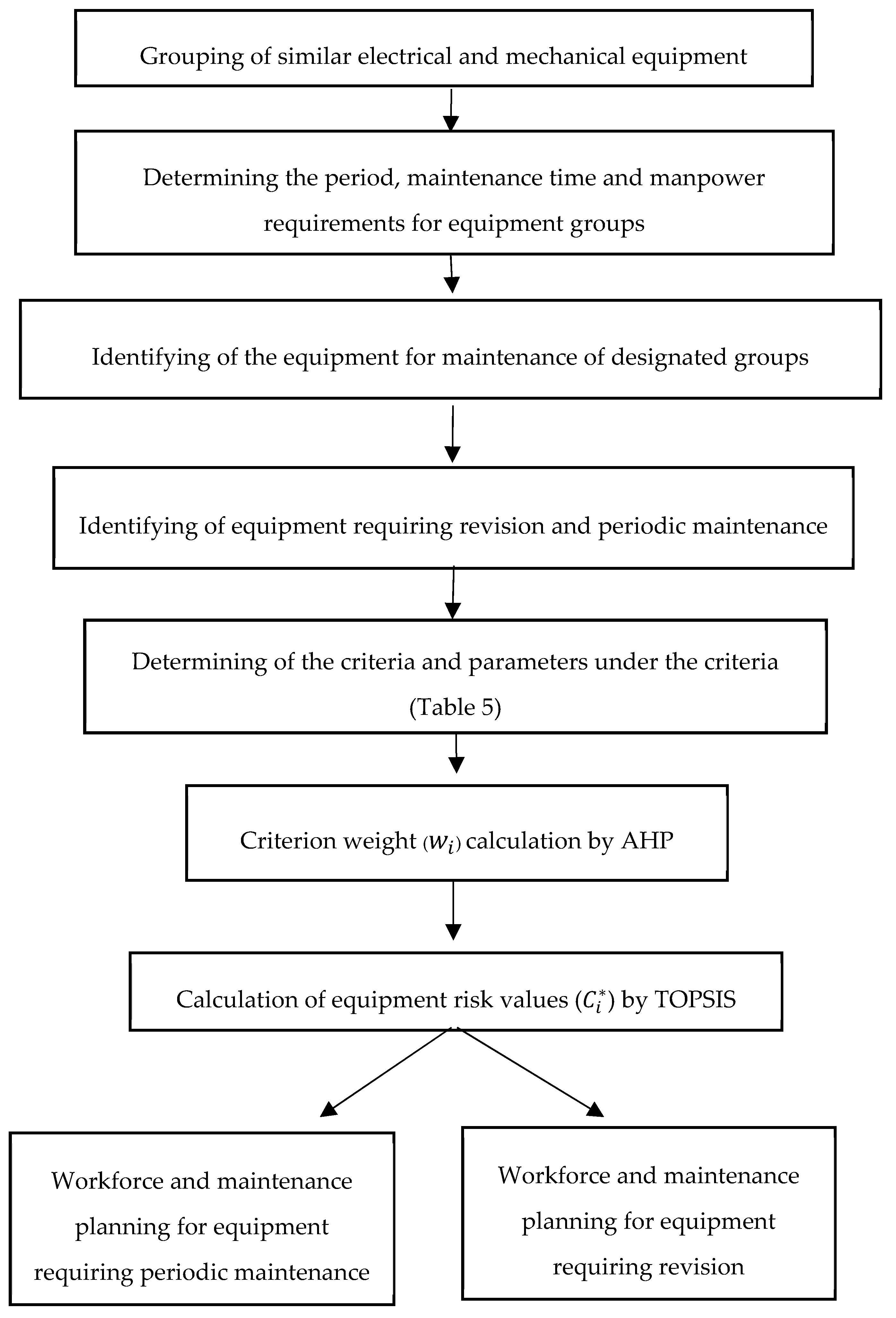
4. Material and Method

4.1. AHP

The AHP method developed by Saaty [47] is used as a singular or supportive method in many decision-making problems, and it is increasing worldwide due to its popularity increasing personal prejudice and providing ease of implementation. Areas of application range from public administration to business [48], industry [49] to health sector, transportation [50] problems to education and automotive [51] This method allows individuals to define priorities between criteria and alternatives in the decision-making process, together with qualitative and quantitative judgments [52].
Application steps of AHP are given below [47]:
Step 1: The purpose of the decision-maker is to include the criteria and alternatives that affect this purpose, and to determine the relationships between them and to create a hierarchical structure.
Step 2: It is carried out by experts by comparing all criteria and alternatives according to their degree of importance. At this stage, the significance scale, which is developed by Saaty and given in Table 1, is used.
The decision maker uses Table 1 to form the pairwise comparison matrix ( A ). This matrix is a symmetric matrix. In other words, the inverse of the priority comparisons on the matrix diagonal according to the multiplication forms the cells located under the diagonal, e.g., a 21 = 1 / a 12 . The n in the matrix A given in Equation (1) shows the number of criteria.
A = [ a 11 a 12 a 1 n a 21 a 22 a 2 n . . . . . . a n 1 a n 2 a n n ] .
Step 3: The generated comparison matrix is normalized. By using the column vectors in the pairwise comparison matrix, n pieces and n-component B column vector is formed (Equation (2)).
B i = [ b 11 b 21 . . . b n 1 ]     i = 1 , 2 , , n .
This normalization is performed by dividing each value in each matrix by column totals (Equation (3)).
b i j = a i j i = 1 n a i j     i , j = 1 , 2 , , n
Step 4: After normalization, the priority or weight vectors for the items compared in the hierarchy are calculated. n pieces B column vector is combined in a matrix format. The arithmetic means of the row components of the generated matrix are obtained with Equation (4).
w i = i = 1 n b i j / n     i , j = 1 , 2 , , n .
The W i   vector, consisting of n pieces w i , shows the importance of the criteria according to each other (Equation (5)).
W i = [ w 1 w 2 . . . w n ]     i = 1 , 2 , , n .
Step 5: The consistency ratio (CR) of the judgments in each paired comparison matrix should be calculated in order to measure whether the decision-maker has consistently compared the values in the hierarchy to the elements in the hierarchy. In order to calculate the CR value, the first basic value (λ) of the binary comparison matrix must be calculated using Equations (6)–(8). The D   column vector is obtained by multiplying the matrix A with the W priority vector (Equation (6)). The basic value vector ( E ) of each evaluation criterion is obtained by proportioning the reciprocal elements of the D column vector and the W column vector (Equation (7)). The arithmetic mean of these values gives the basic value ( λ ) (Equation (8)).
D = [ a 11 a 12 a 1 n a 21 a 22 a 2 n . . . . . . a n 1 a n 2 a n n ] × [ w 1 w 2 . . . w n ]
E i = d i / w i     i = 1 , 2 , , n
λ = i = 1 n E i / n     i = 1 , 2 , , n .
After this phase, the consistency index (CI) is calculated with Equation (9). n refers to the size of the matrix in the equation.
C I = ( λ n ) / ( n 1 ) .
The calculated CI value is used for CR calculation by dividing Random Index (RI) given in Table 2 (Equation (10)).
C R = C I / R I .
If CR less than 0.1 indicates that the application is consistent. Otherwise, the pairwise comparison matrices are revised, and the steps are repeated.
Step 6: In the analysis phase of AHP scores, the highest value alternative is chosen as the best alternative.

4.2. TOPSIS

The TOPSIS method was developed by Hwang and Yoon [53] in 1981 and is a method commonly used in real life multi-criteria decision problems. This method allows decision-makers to compare and sort alternatives. TOPSIS selects the alternative that is closest to the ideal and the ideal solution to the ideal solution. TOPSIS sorts the alternatives based on the distance from the nearest positive ideal solution and the distance from the nearest negative ideal solution and selects the alternative closest to the ideal solution. It is used as a field of application from the aircraft industry to the health sector [54], from logistics to energy [55] with a long sectoral perspective. In order to determine the critical levels of the equipment’s risks due to the use of the qualitative information related to the problem, to realize the alternative ranking easily and effectively, to use the complex structure of the problem frequently in the literature and to properly reflect the nature of the problem, the TOPSIS method has been preferred. The method consists of six steps [53].
Step 1: The criteria that are effective in decision making in the columns, and the decision matrix ( A i j ) are formed in the lines with the alternatives to be ordered. n is the number of criteria and m is the number of alternatives. For example, a 21 refers to the value of the second alternative to the first criterion. The entire matrix is filled in this way. A i j matrix is given in Equation (11).
A i j = [ a 11 a 12 a 1 n a 21 a 22 a 2 n . . . . . . a m 1 a m 2 a m n ]     i = 1 m ;    j = 1 n .
Step 2: The standard decision matrix ( R ) is created with the help of Equation (12). a k j refers to the value of kth row in the column j. The new matrix ( R i j ) obtained by the application of Equation (12) to the A i j matrix is given in Equation (13).
r i j = a i j / k = 1 m a k j 2     i = 1 m ;    j = 1 n ;    k = 1 m
R i j = [ r 11 r 12 r 1 n r 21 r 22 r 2 n . . . . . . r m 1 r m 2 r m n ]     i = 1 m ;    j = 1 n .
Step 3: Weight ratios are determined in order to evaluate the criteria. Weight vector indicated by W i . The total weight of all criteria must be 1. The weighted standard decision matrix (V) is then obtained by multiplying each weight value with the value of the relevant criterion in the standard decision matrix (Equation (14)).
V i j = [ w 1 r 11 w 2 r 12 w n r 1 n w 1 r 21 w 2 r 22 w n r 2 n . . . . . . w 1 r m 1 w 2 r m 2 w n r m n ]     i = 1 m ;    j = 1 n .
Step 4: According to the assumption that the criteria are monotonically increasing and have a monotonous decreasing trend, the maximum and minimum values ( v i j = w i r i j ) in the weighted standard decision matrix ( V i j ) are determined as ideal (A*) (Equation (15)) and negative ideal ( A ) (Equation (17)) solutions. The solution sets obtained for A* and A are shown in Equation (16) and Equation (18) respectively. The J in the Equations (15) and (17) show the benefit (maximization) and J represents the loss (minimization) value.
A * = { ( m a x i v i j | j J ) , ( m i n i v i j | j J }
A * = { v 1 * , v 2 * , , v n * }
A = { ( m i n i v i j | j J ) , ( m a x i v i j | j J }
A = { v 1 , v 2 , , v n } .
Step 5: Separation measures are calculated as the distance of the criteria values of each decision point in the matrix to the ideal ( S i * ) and negative ideal solution ( S i ) by using Equations (19) and (20). The number of S i *   and S i   equals to the number of alternatives (m).
S i * = j = 1 n ( v i j v j * ) 2     i = 1 m ;    j = 1 n
S i = j = 1 n ( v i j v j ) 2     i = 1 m ;    j = 1 n .
Step 6: The relative closeness to the ideal solution ( C i * ) is calculated by using Equation (21). It also refers to the share of the negative ideal separation measure in the total separation.
C i * = S i S i + S i *     i = 1 m .
The value of C i * is in the range of 0–1. Taking this value to 1 means that the decision point is the ideal solution, and 0 means the absolute proximity of the decision point to the negative ideal solution [56].

5. Case Study

In particular, population growth, industrialization and urbanization with constantly evolving technology, the demand for electrical energy in Turkey in the last decade the average annual increase was 5.6%. At the same time zone while falling electricity consumption per person in Turkey reached 64.4% increase from 2052 kWh to 3373 kWh. Hydroelectric power facilities, the increase in demand for this important place in Turkey meets one-fifth [57]. Therefore, uninterruptible power production Turkey has critical importance in terms of energy supply security. Considering the fact that one of the two pillars of sustainable energy supply in power generation plants is maintenance management, the critical importance of maintenance planning in hydroelectric power plants emerges [1].
In this context, in this study, each having 200 MW of five units and electrical, mechanical, measurement and control equipment grouped total 6111 equipment with a large-scale hydroelectric power plant in Turkey in 1404 in electrical equipment and in 1063 mechanical equipment maintenance scheduling problems are discussed. In response to such a large number of equipment, this maintenance procedure has been developed in order to increase the ratio of labor and time source, increase in the amount of electrical energy obtained from the potential energy of 1 m3 water to efficiency and the direct effect of this on the supply security. This procedure is to determine the most critical ones for the system from electrical and mechanical equipment 2467 and to perform maintenance starting from the equipment with a high degree of importance. The importance levels of power plant equipment for power plant equipment were determined by using the AHP method which is frequently used for these problems in the literature, and by using the TOPSIS method which is one step prominent with the significant results of the ease and ease of application between the sorting algorithms of these weights. The steps of the application are given in Figure 2.
After the data sets of the equipment have been formed, it has been started to determine the maintenance for the 2467 equipment. The reason for this analysis for each equipment is that the maintenance of some equipment is not necessary because the equipment cannot be serviced, the maintenance is unnecessary and/or in case of failure, the equipment exchange is both easy and more economical than in maintenance. This equipment is usually of low importance for the system. Buses, relays, surge arresters, thermometers, switches, indicators, coolers, heaters, and lighting systems are maintenance-free equipment from the electrical equipment group. The mechanical equipment group consists of filters, control valves, thermometer, indicators and water measuring systems and 318 non-maintenance equipment. After determining whether the equipment is for maintenance or not, equipment grouping has been done within the scope of revision maintenance. Because the facility has periodic maintenance, revision maintenance, or both revision and periodic maintenance equipment. However, another reason for grouping is that revision maintenance has long-term requirements and maintenance requires unit durations during the maintenance phase. The number of electrical and mechanical equipment requiring revision is 200 and 278, respectively, and the revision maintenance information for the equipment is given in Table 3 and Table 4. The revision maintenance period is 4 years for each equipment subject to revision at the plant under consideration. In addition, the competencies of the personnel performing maintenance on electrical and mechanical equipment at the existing facility are different and 12 maintenance staff have been assigned to the electrical equipment 12 and to the mechanical equipment.

5.1. Calculation of Risk Levels of Equipment in Terms of Facility

After the above-mentioned grouping is realized for electrical and mechanical equipment, the next step is to determine the importance of the equipment in terms of the electrical production system. At this stage, firstly, the criteria affecting the importance of each equipment group were determined by the facility experts. In order to obtain more analytical results with these evaluation criteria, parameters and numerical values scale corresponding to these parameters were formed. The criteria, parameters and numerical values scale are given in Table 5. The scale was designed in line with the common beliefs of the plant experts in the range of 1–10, with a 10-point assignment to the highest impact, and by comparing all other parameters to the highest point in terms of the sustainable energy supply in the power facility. For example, when the failure occurred (for the criterion of possible consequences), the unit stopped taking production as unplanned (because it disrupted the sustainable energy supply), while the unit took seven pre-maintenance conditions. Likewise, the option that is always available for the warehouse reserve criterion is valid for consumables and the effect of this parameter on the sustainable energy supply in the power plant is one when compared to the unit stoppage. After the scale was created, the weighting of the criteria was started. At this stage, a comparison matrix was established with the joint decision of the plant experts.
First of all, binary comparison matrices are formed by using the scale given in Section 4.1 and the double comparison matrix of the criteria is given in Appendix A. Then, the normalized decision matrix and weight vector described in Step 3 and Step 4 were calculated respectively. Whether the calculated weights were consistent was calculated by the procedures described in Step 5. The consistency rate was found to be 0.032 and it is less than 0.1, so the test result is consistent. In this context, weights are given in Table 6. After the calculation of the benchmark weights, the stage of determining the importance of the equipment was started. In this stage, the TOPSIS method, which is frequently used in the literature, is used in order to solve problems of multi-criteria decision-making methods. First of all, the verbal values of each criterion are assigned for each equipment with the help of parameters determined under the criteria.
When applying the TOPSIS method, the values in the decision matrix must be numerical. For this reason, the matrix consisting of the verbal values of the equipment is made numerical using the scale given in Table 5. As a result of this transformation, 2467 × 9 dimension initial decision matrix was formed and TOPSIS method solution was started. Since the matrix size is too large, the sample values of the decision matrix are given in Appendix B. Weighted normalized decision matrix was formed by using the benchmark weights obtained with AHP and ideal and negative ideal solution clusters were determined. Then, with Equations (19) and (20) the ideal and negative ideal distinction measurements were calculated for each equipment, and equipment priority values (C*), which were defined as the relative closeness of each equipment to the ideal solution, were found with Equation (21). For some equipment C* values are given in Table 7. All calculations and the obtained values in both AHP and TOPSIS steps were carried out by using the MS Excel program as it is an easy alternative for general purpose and problem structure. The priority values of the equipment, which are calculated by the integration of AHP and TOPSIS, are very important for the inclusion of maintenance staff who are insufficient in terms of the labor force in maintenance planning in order to add maximum added value to the power plant. Due to the main priority for the power facility system, starting from the equipment to do maintenance, efficient operation of the equipment in the facility, maximizing the amount of electricity production and power facility contributes to the security of the energy supply directly serves the basic purposes. For this reason, the maintenance planning in the continuation of the study was carried out on the basis of the equipment priority values.

5.2. Revision and Periodic Maintenance Planning

As a result of the classifications, 416 of 1404 electrical equipment were required to be serviced. Of the 416 equipment for maintenance, only 216 are periodic, 104 are revised only and 96 are periodic and revision maintenance is required. In the group of mechanical equipment, 670 of 1063 equipment are for maintenance. Of the mechanical equipment subject to 670 maintenance, 105 are in revision only, 392 in periodic only and 173 in both the revision and periodic maintenance. Accordingly, the 478 equipment is subject to revision maintenance and must be performed during the revision periods of the equipment. The number of working days per year is around 250. The competencies to perform maintenance are 12 personnel for electrical equipment and 16 personnel for mechanical equipment, and the annual working day capacity of personnel is reduced when considering annual permits and reports. For this reason, one-day working day capacity of each maintenance personnel is taken as 200 days and workforce and maintenance planning is done accordingly. There are two criteria that come to the forefront when we look at the criteria weights obtained by the AHP method and which affect the maintenance given in Table 6. These are the criteria for possible outcomes with pre-maintenance conditions of 0.239 and 0.402, respectively. The sum of these two criteria weights is 0.641 and it is concluded that the maintenance of the power plant consisting of thousands of equipment will be directly served in order to increase the efficiency of maintenance. The reason for the large share of these two criteria on maintenance efficiency is that they are the parameters that directly affect the production of electricity. When the parameters in two critical criteria given in Table 5 are taken into consideration, parameters such as unit stop, load reduction, stopping time, non-redundant operation are noteworthy. These parameters are the parameters that directly affect the energy supply security, but also the importance of the equipment is high according to these criteria.
As a result, due to the purpose of enabling maintenance planning and the great effects on equipment priority levels, scenarios have been produced based on pre-maintenance conditions and possible results criteria and sub-parameters and maintenance planning has been done according to these scenarios.

5.2.1. Revision Maintenance Planning of Electrical Equipment

Two scenarios are derived for the revised equipment of electrical equipment. While creating the planning scenarios, different sub-parameter combinations of pre-maintenance conditions and possible outcome criteria were made. Equipment 1 (S1) is composed of equipment that requires stopping or pre-maintenance post-maintenance, and equipment resulting in unit downtime when defective. As in all enterprises, this equipment which is directly affecting the maximum production, which is the main objective in the power plants, is very important equipment for the power facility. The importance levels of S1 equipment expressed in C* range from 85.81–100, which proves how important the equipment is. The number of equipment in this group is 192, which is the priority group for electrical equipment requiring revision. In Scenario 2 (S2), equipment that does not require post-maintenance posture and missing the task when defective has formed a group. At the same time, this group remains the same when the equipment belonging to the revised electrical equipment group S1 is removed. In other words, there is no need to create another scenario for maintenance planning of electrical equipment. There are eight pieces of equipment belonging to this group. The data required for S1 and S2 maintenance planning are given in Table 8.
The total number of maintenance periods for equipment separated by scenarios is 12 staff, which is divided by the number of staff and the time allocated to the team, this data is calculated in minutes and maintenance staff working 8 h a day for 480 h (8 × 60) divided by the net time requirement and since it is a 5-unit power plant, the net time is divided by the number of units per unit of time requirement data. At the same time, according to the scenarios in the table, equipment priority values are also given. The priority values of S1 were found to be greater than the priority values of S2 and therefore it was concluded that the equipment in S1 should be serviced firstly.

5.2.2. Revision Maintenance Planning of Mechanical Equipment

Three scenarios were created for the revised mechanical equipment. Scenario 1 (S1) has been created to group equipment with unit downtimes both before maintenance and when equipment is malfunctioning. It is an indication of how critical equipment the equipment is when it stops both during the pre-maintenance preparation and at any time when it breaks down. This is supported by equipment priority values ranging from 95.91 to 97.97, and it is understood that the group that requires first maintenance in revision periods of mechanical equipment is equipment belonging to S1. In Scenario 2 (S2), there is equipment that does not require posture before maintenance and cause the unit to stop when it fails. Although this situation is not as important as in S1, it is a big risk for the unit to stop when it fails and their maintenance should be done urgently to prevent breakdown. For this reason, after completing the maintenance of the equipment in S1, revision maintenance of equipment belonging to S2 should be started. Scenario 3 (S3) consists of the equipment subject to revision, except for the equipment subject to revision S1 and S2, which does not require pre-maintenance posture, but the defective task condition. It is a scenario created with the same strategy as S2 from the electrical equipment subject to revision. The data of these three scenarios for mechanical equipment requiring revision are given in Table 9.
The maintenance planning procedure of the electrical equipment subject to revision and the maintenance procedure of the mechanical equipment was operated in the same way. There are 16 staff who have maintenance on mechanical equipment and calculations are made accordingly. As a result of the calculations, a total of 278 revisions are required for 54 days per unit for mechanical equipment requiring maintenance.

5.2.3. Periodic Maintenance Planning of Electrical Equipment

Revision of electrical equipment is 17 days per year. There are active 200 days in a year and the time required for revision maintenance is calculated and the period to be devoted to periodic maintenance is calculated as 183 days. Three scenarios for periodic maintenance planning are discussed. In Scenario 1 (S1), equipment that interrupts the unit in the event of a failure of the equipment and the unit stopping before the maintenance is combined. Equipment priority values range from 94.16–100 and consist of critical equipment for the system. In Scenario 2 (S2), pre-maintenance conditions are the same as S1 but the possible results are composed of different parameters. These parameters are; failure of the malfunction and damage to equipment associated with the equipment, damage to safety, problems in start-up and non-redundant operation. Finally, although Scenario 3 (S3) does not require downtime prior to maintenance, equipment that can pose problems in emergency situations, risk the production by having a fail-safe operation when it fails, or cause problems by replacing it with a replacement, cause the size of the failure to grow and cause damage to the associated equipment. In line with these scenarios created for electrical equipment, firstly according to scenarios (S1 first, then S2 was finally planned for maintenance of equipment in S3), maintenance planning based on a maintenance priority was taken into consideration in the scenarios taking the equipment priority values into consideration. Table 10 shows the maintenance and labor planning of the equipment allocated according to the scenarios. As indicated in the table, it is sufficient for the periodic maintenance of 312 electrical equipment for 79 days.

5.2.4. Periodic Maintenance Planning of Mechanical Equipment

The number of mechanical equipment requiring both revision and periodic maintenance or just periodic maintenance is 565 pieces. There are 16 staff who have competencies to perform this equipment and 54 of their annual working day capacity is devoted to revised mechanical equipment. As previously mentioned, the capacity of 200 working days a year is discussed. The planned periodic maintenance should be carried out outside the revision maintenance process as the staff are partners. In accordance with the maintenance philosophy developed, the scenarios for the periodic maintenance equipment of the mechanical equipment are derived. In Scenario 1 (S1), since the number of mechanical equipment subject to periodic maintenance is very high, only pre-maintenance conditions and possible results are taken into consideration only in equipment with unit standstill and 374 of 565 equipment are included in this scenario. Equipment priority values range from 95.91 to 97.97, which is very critical equipment for the system. For this reason, priority should be given to the planning of trustee planning. Scenario 2 (S2) includes equipment that may cause a standstill or posture in pre-maintenance conditions and possible consequences resulting in a non-redundant operation and production risk. Scenario 3 (S3) does not require downtime prior to maintenance, but redundant operation, missing task, damage to safety, creates problems in emergency situations, increases breakdown and damage to related equipment possible result parameters are included. Maintenance and labor planning were made based on these scenarios and equipment priority values. The planning data for 565 pieces of equipment distributed to the scenarios are given in Table 11.

6. Conclusions

Maintenance is a difficult process to manage due to production disruption due to the interruption of production during the process, costly in terms of time, labor and material requirement and due to the specific limitations of these components. In this context, in this study, an application has been realized based on the importance of maintenance planning on the amount of electricity generation and costs, positive effect on energy supply security and increased energy efficiency. Discussed the company, which has great significance for Turkey’s renewable energy supply is one of the hydroelectric power facility. When the studies in the literature are examined, maintenance planning is taken into consideration that the equipment to be maintained is shaped according to the risks they carry in terms of the system and the multi-purpose and multi-criteria structure of the problem is taken into consideration. Considering these two factors, the parameters affecting the maintenance with AHP were weighted and these weights were calculated using the TOPSIS methodology and the risk values (equipment priority value) carried by the equipment in terms of the system were calculated. Recognizing the priority of maintenance on equipment that has a direct effect on the system will be effective in terms of system efficiency as well as providing an easy way to manage complex system structure. In this context, maintenance and workforce planning were made according to the equipment priority values calculated in this study and the different scenarios created by two parameters that most affected these values. The result of the planning requires 96 working days for electrical equipment for maintenance and 110 for mechanical equipment. The remaining business days are reserved for unexpected failures. The reason for this is that the electricity generation facilities have complex structures and the facilities where faults occur, no matter how much maintenance is done. Furthermore, another proof of this is the revision and the periodic maintenance strategy in electricity generation plants as well as incidental maintenance. For these reasons, the remaining working days are planned to be allocated to faulty maintenance. In this study, the proposed maintenance planning and maintenance plan were created for all the equipment subject to maintenance and also enough time has been devoted to the inevitable failure of the hydroelectric power facility. The fact that there is sufficient time for these faults indicates that maintenance planning is realistic. As a result, in this study, it is aimed to place periodic maintenance culture in the system analysis and design result obtained in a hydroelectric power facility following the incidental and revision maintenance policies and to distribute the labor force effectively throughout the year. As a result of the appointment of the limited staff in the electrical and mechanical equipment to the maintenance plans prepared according to the risk levels of the equipment in terms of the power plant, an effective labor force is used without requiring overtime. As a result of the 2-year follow-up of the maintenance plans including the periods extending from the weekly period to the 4-year period, all the factors that hamper the sustainable energy supply have been eliminated, and in other words, a 100% improvement in the production stops due to lack of maintenance has been achieved. As a continuation of this study, it is thought that all equipment in the hydroelectric power plant will be considered and will contribute to the literature by using mathematical modeling techniques and the use of meta-intuitions in the planning of labor planning or material requirements.

Author Contributions

The analyses were carried out by R.Y. and E.Ö. This paper was written by R.Y., T.E. and E.Ö. supervised the conducted research, reviewed, and revised the paper. E.Ö. reviewed, revised, and improved the paper.

Funding

This research received no external funding.

Conflicts of Interest

The authors declare no conflict of interest

Symbols and Acronyms

Acronyms/SymbolsExplanation
AHPAnalytic Hierarchy Process
AmAlternative m (mth equipment which is shown in Appendix B)
BDTBoolean Decision Tree
C1Criteria 1 (Warehouse backup)
C2Criteria 2 (Maintenance pre-conditions)
C3Criteria 3 (Additional work requirement)
C4Criteria 4 (Failure period)
C5Criteria 5 (Possible consequences)
C6Criteria 6 (Availability of measuring equipment)
C7Criteria 7 (Static, dynamic or electrical property of equipment)
C8Criteria 8 (Fault shooting time)
C9Criteria 9 (Detectability of failure)
ELECTREElimination and Choice Translating Reality English
FMEAFailure Modes and Effects Analysis
PROMETHEEPreference Ranking Organization Method for Enrichment Evaluation
S1Scenario 1
S2Scenario 2
S3Scenario 3
WSMWeighted Total Model
I&CInstrumentation and Control
AComparison matrix (in AHP)
aijComparison matrix element (in AHP)
BiB column vectors (in AHP)
bijB column vector element (in AHP)
WiWeight vector (in AHP)
wiWeight vector element (in AHP)
DD column vector (in AHP)
diD column vector element (in AHP)
EiBase value vector (in AHP)
λBasic value (in AHP)
CIConsistency index (in AHP)
RIRandom index (in AHP)
CRConsistency ratio (in AHP)
AijDecision matrix (in TOPSIS)
aijDecision matrix element (in TOPSIS)
RijStandard decision matrix (in TOPSIS)
rijStandard decision matrix element (in TOPSIS)
VijWeighted standard decision matrix (in TOPSIS)
vijWeighted standard decision matrix element (in TOPSIS)
A*Ideal solution set (in TOPSIS)
A-Negative ideal solution set (in TOPSIS)
v*Ideal solution set element (in TOPSIS)
v-Negative ideal solution set element (in TOPSIS)
Si*Ideal solution (in TOPSIS)
Si-Negative ideal solution (in TOPSIS)
Ci*Closeness to ideal solution (in TOPSIS)

Appendix A

Table A1. Pairwise comparison matrix.
Criteria/CriteriaC1C2C3C4C5C6C7C8C9
C11.0000.2002.0001.0000.1111.0001.0002.0001.000
C25.0001.0009.0004.0000.2004.0005.0009.0005.000
C30.5000.1111.0000.3330.1110.5000.5001.0001.000
C41.0000.2503.0001.0000.1431.0001.0003.0001.000
C59.0005.0009.0007.0001.0007.0008.0009.0003.000
C61.0000.2502.0001.0000.1431.0001.0002.0001.000
C71.0000.2002.0001.0000.1251.0001.0002.0001.000
C80.5000.1111.0000.3330.1110.5000.5001.0000.500
C91.0000.2001.0001.0000.3331.0001.0002.0001.000

Appendix B

Table B1. Decision matrix sample.
Alternative/CriteriaC1C2C3C4C5C6C7C8C9
A1215271123
A21752103133
A31752103133
A41752103133
A51752103133
A61752103133
A71752103133
A81752103133
A91752103133
A101752103133
A11365173133
A123752103133
A133752103133
A143752103133
A15315273121
A16315273121
A17315273121
A18215121131
A19215121131
A20215121131
A21215121131
A22215121131
A23215121131
A24215121131
A25215121131
A26215121131
A27215121131
A28215121131
A293752103133
A303752103133

References

  1. Özcan, E.C.; Ünlüsoy, S.; Eren, T. A combined goal programming—AHP approach supported with TOPSIS for maintenance strategy selection in hydroelectric power plants. Renew. Sustain. Energy Rev. 2017, 78, 1410–1423. [Google Scholar] [CrossRef]
  2. Márquez, A.C. The Maintenance Management Framework: Models and Methods for Complex Systems Maintenance; Springer Science & Business Media: Berlin, Germany, 2007. [Google Scholar]
  3. Özcan, E. Bakım Yönetim Sistemi: Kurulum ve İşletme Esasları; Elektrik Üretim, A.Ş., Ed.; Yayınları: Ankara, Turkey, 2016. [Google Scholar]
  4. YEGM. Yenilenebilir Enerji Kaynaklarından Elektrik Üreten Tesislerin Kurulu Güç Gelişimi. 2018. Available online: http://www.yegm.gov.tr/yenilenebilir.aspx (accessed on 18 April 2019).
  5. TEİAŞ. Aylık Elektrik İstatistikleri. 2018. Available online: https://www.teias.gov.tr/tr/elektrik-istatistikleri (accessed on 1 October 2018).
  6. Başeşme, H. Hidroelektrik Santrallar ve Hidroelektrik Santral Tesisleri; EÜAŞ Genel Müdürlüğü Hidrolik Santraller Dairesi Başkanlığı: Ankara, Turkey, 2003. [Google Scholar]
  7. Bonsor, K. Hydraulic Power Plant. HowStuffWorks. 2019. Available online: https://science.howstuffworks.com/environmental/energy/hydropower-plant1.htm) (accessed on 18 April 2019).
  8. Zhang, C.; Gao, W.; Guo, S.; Li, Y.; Yang, T. Opportunistic maintenance for wind turbines considering imperfect, reliability-based maintenance. Renew. Energy 2017, 103, 606–612. [Google Scholar] [CrossRef]
  9. Alaswad, S.; Xiang, Y. A review on condition-based maintenance optimization models for stochastically deteriorating system. Reliab. Eng. Syst. Saf. 2017, 157, 54–63. [Google Scholar] [CrossRef]
  10. Khan, F.I.; Haddara, M.M. Risk-based maintenance (RBM): A quantitative approach for maintenance/inspection scheduling and planning. J. Loss Prev. Process Ind. 2003, 16, 561–573. [Google Scholar] [CrossRef]
  11. Krishnasamy, L.; Khan, F.; Haddara, M. Development of a risk-based maintenance (RBM) strategy for a power-generating plant. J. Loss Prev. Process Ind. 2005, 18, 69–81. [Google Scholar] [CrossRef]
  12. Doostparast, M.; Kolahan, F.; Doostparast, M. A reliability-based approach to optimize preventive maintenance scheduling for coherent systems. Reliab. Eng. Syst. Saf. 2014, 126, 98–106. [Google Scholar] [CrossRef]
  13. Kobbacy, K.A.H. Application of Artificial Intelligence in maintenance modelling and management. IFAC Proc. Vol. 2012, 45, 54–59. [Google Scholar] [CrossRef]
  14. Carlos, S.; Sanchez, A.; Martorell, S.; Villanueva, J. Advances in Engineering Software Particle Swarm Optimization of safety components and systems of nuclear power plants under uncertain maintenance planning. Adv. Eng. Softw. 2012, 50, 12–18. [Google Scholar] [CrossRef]
  15. Chalabi, N.; Dahane, M.; Beldjilali, B.; Neki, A. Computers & industrial engineering optimisation of preventive maintenance grouping strategy for multi-component series systems: Particle swarm based approach. Comput. Ind. Eng. 2016, 102, 440–451. [Google Scholar] [CrossRef]
  16. Upasani, K.; Bakshi, M.; Pandhare, V.; Kumar, B. Computers & industrial engineering. Comput. Ind. Eng. 2017, 108, 1–14. [Google Scholar] [CrossRef]
  17. Borgonovo, E.; Marseguerra, M.; Zio, E. A Monte Carlo methodological approach to plant availability modeling with maintenance, aging and obsolescence. Reliab. Eng. Syst. Saf. 2000, 67, 61–73. [Google Scholar] [CrossRef]
  18. Marseguerra, M.; Zio, E.; Podofillini, L. Condition-based maintenance optimization by means of genetic algorithms and Monte Carlo simulation. Reliab. Eng. Syst. Saf. 2002, 77, 151–165. [Google Scholar] [CrossRef]
  19. Arzaghi, E.; Mahdi, M.; Abbassi, R.; Garaniya, V. Risk-based maintenance planning of subsea pipelines through fatigue crack growth monitoring. Eng. Fail. Anal. 2017, 79, 928–939. [Google Scholar] [CrossRef]
  20. Lapa, C.M.F.; Pereira, C.M.N.A.; e Melo, P.F.F. Surveillance test policy optimization through genetic algorithms using non-periodic intervention frequencies and considering seasonal constraints. Reliab. Eng. Syst. Saf. 2003, 81, 103–109. [Google Scholar] [CrossRef]
  21. Levitin, G.; Lisnianski, A. Joint redundancy and maintenance optimization for multistate series—Parallel systems. Reliab. Eng. Syst. Saf. 1999, 64, 33–42. [Google Scholar] [CrossRef]
  22. Busacca, P.G.; Marseguerra, M.; Zio, E. Multiobjective optimization by genetic algorithms: Application to safety systems. Reliab. Eng. Syst. Saf. 2001, 72, 59–74. [Google Scholar] [CrossRef]
  23. Xia, X. Control problems in building energy retrofit and maintenance planning. Annu. Rev. Control 2017, 44, 78–88. [Google Scholar] [CrossRef]
  24. Gopalakrishnan, M.; Skoogh, A.; Laroque, C. Simulation-based planning of maintenance activities in the automotive industry. In Proceedings of the Winter Simulations Conference (WSC), Washington, DC, USA, 8–11 December 2013. [Google Scholar] [CrossRef]
  25. Ilangkumaran, M.; Kumanan, S. Selection of maintenance policy for textile industry using hybrid multi-criteria decision making approach. J. Manuf. Technol. Manag. 2009, 20, 1009–1022. [Google Scholar] [CrossRef]
  26. Arunraj, N.S.; Maiti, J. Risk-based maintenance policy selection using AHP and goal programming. Saf. Sci. 2010, 48, 238–247. [Google Scholar] [CrossRef]
  27. Hu, H.; Cheng, G.; Li, Y.; Tang, Y. Risk-based maintenance strategy and its applications in a petrochemical reforming reaction system. J. Loss Prev. Process Ind. 2009, 22, 392–397. [Google Scholar] [CrossRef]
  28. Froger, A.; Gendreau, M.; Mendoza, J.E.; Pinson, É.; Rousseau, L. Maintenance scheduling in the electricity industry: A literature review. Eur. J. Oper. Res. 2016, 251, 695–706. [Google Scholar] [CrossRef]
  29. Yssaad, B.; Abene, A. Rational reliability centered maintenance optimization for power distribution systems. Int. J. Electr. Power Energy Syst. 2015, 73, 350–360. [Google Scholar] [CrossRef]
  30. Sheikhalishahi, M.; Azadeh, A.; Pintelon, L. Dynamic maintenance planning approach by considering grouping strategy and human factors. Process Saf. Environ. Prot. 2017, 107, 289–298. [Google Scholar] [CrossRef]
  31. Wang, K.; Zhang, B.; Wu, X.; Zhai, J.; Shao, W.; Duan, Y. Multi-time Scales Coordination Scheduling of Wind Power Integrated System. In Proceedings of the IEEE PES Innovative Smart Grid Technologies ASIA (ISGT Asia 2012), Tianjin, China, 21–24 May 2012; pp. 1–4. [Google Scholar]
  32. Backlund, F.; Hannu, J. Can we make maintenance decisions on risk analysis results? J. Qual. Maint. Eng. 2002, 8, 77–91. [Google Scholar] [CrossRef]
  33. Harnly, J.A. Risk based prioritization of maintenance repair work. Process Saf. Prog. 1998, 17, 32–38. [Google Scholar] [CrossRef]
  34. Arunraj, N.S.; Maiti, J. Risk-based maintenance—Techniques and applications. J. Hazard. Mater. 2007, 142, 653–661. [Google Scholar] [CrossRef]
  35. Chareonsuk, C.; Nagarur, N.; Tabucanon, M.T. A multicriteria approach to the selection of preventive maintenance intervals. Int. J. Prod. Econ. 1997, 49, 55–64. [Google Scholar] [CrossRef]
  36. Chybowski, L.; Gawdzińska, K. On the Present State-of-the-Art of a Component Importance Analysis for Complex Technical Systems. In New Advances in Information Systems and Technologies; Springer: Cham, Germany, 2016; pp. 691–700. [Google Scholar]
  37. Chybowski, L.; Gawdzińska, K. On the Possibilities of Applying the AHP Method to a Multi-Criteria Component Importance Analysis of Complex Technical Objects. In New Advances in Information Systems and Technologies; Springer: Cham, Germany, 2016; pp. 701–710. [Google Scholar]
  38. Dey, P.K. A risk-based model for inspection and maintenance of cross-country petroleum pipeline. J. Qual. Maint. Eng. 2001, 7, 25–43. [Google Scholar] [CrossRef]
  39. Moazami, D.; Behbahani, H.; Muniandy, R. Expert systems with applications pavement rehabilitation and maintenance prioritization of urban roads using fuzzy logic. Expert Syst. Appl. 2011, 38, 12869–12879. [Google Scholar] [CrossRef]
  40. Chybowski, L.; Twardochleb, M.; Wiśnicki, B. Multi-criteria decision making in components importance analysis applied to a complex marine system. NAŠE MORE 2016, 63, 264–270. [Google Scholar] [CrossRef]
  41. Dhanisetty, V.S.V.; Verhagen, W.J.C.; Curran, R.J. Multi-criteria weighted decision making for operational maintenance processes. J. Air Transp. Manag. 2018, 68, 152–164. [Google Scholar] [CrossRef]
  42. De Almeida, A.T. Multicriteria model for selection of preventive maintenance intervals. Qual. ad Relia. Eng. Int. 2012, 28, 585–593. [Google Scholar] [CrossRef]
  43. Certa, A.; Enea, M.; Lupo, T. ELECTRE III to dynamically support the decision maker about the periodic replacements configurations for a multi-component system. Decis. Support Syst. 2013, 55, 126–134. [Google Scholar] [CrossRef]
  44. Ouma, Y.O.; Opudo, J.; Nyambenya, S. Comparison of fuzzy AHP and fuzzy TOPSIS for road pavement maintenance prioritization: Methodological exposition and case study. Adv. Civ. Eng. 2015. [Google Scholar] [CrossRef]
  45. Azadeh, A.; Nazari-Shirkouhi, S.; Hatami-Shirkouhi, L.; Ansarinejad, A. A unique fuzzy multi-criteria decision making: Computer simulation approach for productive operators’ assignment in cellular manufacturing systems with uncertainty and vagueness. Int. J. Adv. Manuf. Technol. 2011, 56, 329–343. [Google Scholar] [CrossRef]
  46. Seiti, H.; Hafezalkotob, A. Developing the R-TOPSIS methodology for risk-based preventive maintenance planning: A case study in rolling mill company. Comput. Ind. Eng. 2019, 128, 622–636. [Google Scholar] [CrossRef]
  47. Saaty, T.L. The Analytical Hierarchy Process. Encyclopedia Biostat. 2005. [Google Scholar] [CrossRef]
  48. Gür, Ş.; Hamurcu, M.; Eren, T. Ankara’da Monoray projelerinin analitik hiyerarşi prosesi ve 0-1 hedef programlama yöntemleri ile seçimi. Pamukkale Üniv. Mühendis. Bilim. Derg. 2017, 23, 437–443. [Google Scholar]
  49. Uçakcıoğlu, B.; Eren, T. Hava Savunma Sanayinde Yatırım Projelerinin Çok Ölçütlü Karar Verme ve Hedef Programlama ile Seçimi. J. Aviat. 2017, 1, 39–63. [Google Scholar] [CrossRef]
  50. Taş, M.; Özlemiş, Ş.N.; Hamurcu, M.; Eren, T. Ankara’da AHP ve PROMETHEE yaklaşımıyla monoray hat tipinin belirlenmesi. Ekon. İşletme Siyaset ve Uluslararası İlişkiler Derg. 2017, 3, 65–89. [Google Scholar]
  51. Özyörük, B.; Özcan, E.C. Analitik Hiyerarşi Sürecinin Tedarikçi Seçiminde Uygulanmasi: Otomotiv Sektöründen Bir Örnek. Süleyman Demirel Üniversitesi İktisadi ve İdari Bilim. Fakültesi Derg. 2008, 13, 133–144. [Google Scholar]
  52. Velasquez, M.; Hester, P.T. An analysis of multi-criteria decision making methods. Int. J. Oper. Res. 2013, 10, 56–66. [Google Scholar]
  53. Hwang, C.-L.; Yoon, K. Methods for multiple attribute decision making. In Multiple Attribute Decision Making; Springer: Berlin, Germany, 1981; pp. 58–191. [Google Scholar]
  54. Taş, C.; Bedir, N.; Eren, T.; Alağaş, H.M.; Çetin, S. AHP-TOPSIS yöntemleri entegrasyonu ile poliklinik değerlendirilmesi: Ankara’da bir uygulama. Sağlık Yönetimi Derg. 2018, 2, 1–16. [Google Scholar]
  55. Özcan, E.C.; Ünlüsoy, S.; Eren, T. ANP ve Topsis yöntemleriyle Türkiye’de yenilenebilir enerji yatırım alternatiflerinin değerlendirilmesi. Selcuk Uni. J. Eng. 2017, 5, 204–219. [Google Scholar] [CrossRef]
  56. Arıbaş, M.; Özcan, U. Akademik Araştırma Projelerinin AHP ve TOPSIS Yöntemleri Kullanılarak Değerlendirilmesi. Politek. Derg. 2016, 19, 163–173. [Google Scholar]
  57. Albayrak, B. 2016 Yılı Bütçe Sunumu. Enerji ve Tabii kaynaklar Bakanlığı. Available online: https://docplayer.biz.tr/17246161-2016-yili-butce-sunumu-t-c-enerji-ve-tabii-kaynaklar-bakani-sayin-dr-berat-albayrak-in-2016-yili-butcesini-tbmm-genel-kurulu-na-sunus-metni.html (accessed on 18 April 2019).
Figure 1. Schematic representation of a reservoir hydropower facility [7].
Energies 12 01502 g001
Figure 2. Application steps.
Energies 12 01502 g002
Table 1. Saaty’s priority scale [47].
Importance ValuesValue Definitions
1Equally important
3Partly more important
5Much more important
7Extremely more important
9Certainly more important
2, 4, 6, 8Intermediate values
Table 2. Random Index (RI) Values.
n1234568910111213
RI000.580.91.121.241.411.451.491.511.481.56
Table 3. Data of electrical equipment groups.
Equipment GroupMaintenance Period (min)Labor Requirement (person)
Switching bus bar disconnectors4803
Generator384018
Warning transformer38403
380 kV switchyard breaker4804
380 kV switchyard current transformer1202
380 kV switchyard voltage transformer1202
Main power transformer24008
Internal transformer2404
Table 4. Data on mechanical equipment.
Equipment GroupMaintenance Period (min)Labor Requirement (person)
Adjusting blade1735518
Oil tank112016
The butterfly valve17508
Snail wheel3608
Turbine96012
Speed Regulator4958
Generator lower top guide bearing1358
Brake system6004
Cooling water structure7206
Suction pipe6158
Table 5. Evaluation criteria.
CriteriaCriteria ParametersNumerical Equivalents of the Parameters
C1Warehouse backupNever3
Sometimes2
All the time1
C2Maintenance pre-conditionsUnit shutdown7
Shutdown by situation6
Shutdown by time5
Maintenance without back up2
Shutdown does not require1
C3Additional work requirementRequired5
Not required1
C4Failure periodMonthly8
Quarterly5
Semi-annually3
Annually2
Long term1
Unknown1
C5Possible consequencesUnit shutdown10
Problem in emergency situation9
Load reduction8
Running without back up7
Equipment shutdown6
Security problem6
Deficient function2
Damage in associated equipment2
Problem in start1
Fluid consumption increase1
C6Availability of measuring equipmentYes3
No1
C7Static, dynamic or electrical property of equipmentMechanical-dynamic2
Mechanical-static1
Electrical1
I and C1
C8Fault shooting timeOne week9
More than one day3
Unknown3
2–8 h2
Less than 2 h1
C9Detectability of failureDifficult3
Easy1
Table 6. Criteria weights.
CriteriaWeights
C1Warehouse backup0.055
C2Maintenance pre-conditions0.239
C3Additional work requirement0.033
C4Failure period0.065
C5Possible consequences0.402
C6Availability of measuring equipment0.058
C7Static, dynamic or electrical property of equipment0.056
C8Fault shooting time0.029
C9Detectability of failure0.062
Table 7. Risk values of some equipment.
Equipment NameC*
220 V DC accumulators27.11
380 kV switchyard current transformer l1 phase95.02
380 kV switchyard voltage transformer l3 phase95.02
380 kV switchyard circuit breaker l3 phase95.02
6.3 kV breakers78.69
A bus bar separator l3 phase100.00
Main hook quick load lifting brake motor7.02
Drive-in drive motors7.02
Pressure less oil tank cooling pump drive motor63.93
Table 8. Revision of electrical equipment maintenance planning scenario details.
SCENARIO DETAILS
Scenario No# Equip.Total Time Requirement (min)Distributed Time Requirement to Team (min)Net Duration (days)Duration per Unit (days)Priority Range of Equipment
S1192477,60039,80082.9216.5885.81–100
S2872006001.250.259.05–9.05
TOTAL200484,80040,4008417-
Table 9. Mechanical equipment revision maintenance planning scenario details.
Scenario Details
Scenario No# Equip.Total Time Requirement (min)Distributed Time Requirement to Team (min)Net Duration (days)Duration per Unit (days)Priority Range of Equipment
S12301,464,480122,040254.2550.8595.91–97.97
S21643,20036007.501.5035.08–35.12
S33259,040492010.252.056.78–8.06
TOTAL2781,566,720130,56027254-
Table 10. Periodic maintenance planning scenario details of electrical equipment.
Scenario Details
NoPeriod# Equip.Total Time Requirement (min)Distributed Time Requirement to Team (min)Net duration requirement (day)Priority Range of Equipment
S11 Week2474,880624013.0095.02–95.02
1 Month72172,80014,40030.0095.02–100
6 Months343203600.7594.16–94.16
S26 Month4970,560588012.2563.93–83.79
1 Year857604801.0078.69–78.69
S31 Month532,64027205.6727.11–27.35
6 Month4053,76044809.336.71–33.37
1 Year11140,08033406.967.02–33.27
Total312454,80037,90079-
Table 11. Periodic maintenance of mechanical equipment planning scenario details.
Scenario Details
NoPeriod# Equip.Total Time Requirement (min)Distributed Time Requirement to Team (min)Net Duration (days)Priority Range of Equipment
S11 Month133107,640672814.0295.91–97.97
3 Month18471,92044959.3695.91–97.83
6 Month4961203830.8096.51–97.54
1 Year819201200.2597.97–97.97
S2 1 Week30101,520634513.2271.42–82.49
3 Month838402400.5075.63–75.63
6 Month41440900.1971.42–82.49
1 Year3040,80025505.3171.42–82.49
2 Year128801800.3882.64
S31 Month3815,7209832.056.78–33.19
3 Month6343,04026905.605.86–26.40
6 Month4429,76018603.885.37–10.52
1 Year71300810.175.86–32.26
2 Year145002810.5926.32
Total565432,40027,02556-

