A Study on Ceiling Temperature Distribution and Critical Exhaust Volumetric Flow Rate in a Long-Distance Subway Tunnel Fire with a Two-Point Extraction Ventilation System


Abstract
:1. Introduction
2. Reduced-Scale Experiments
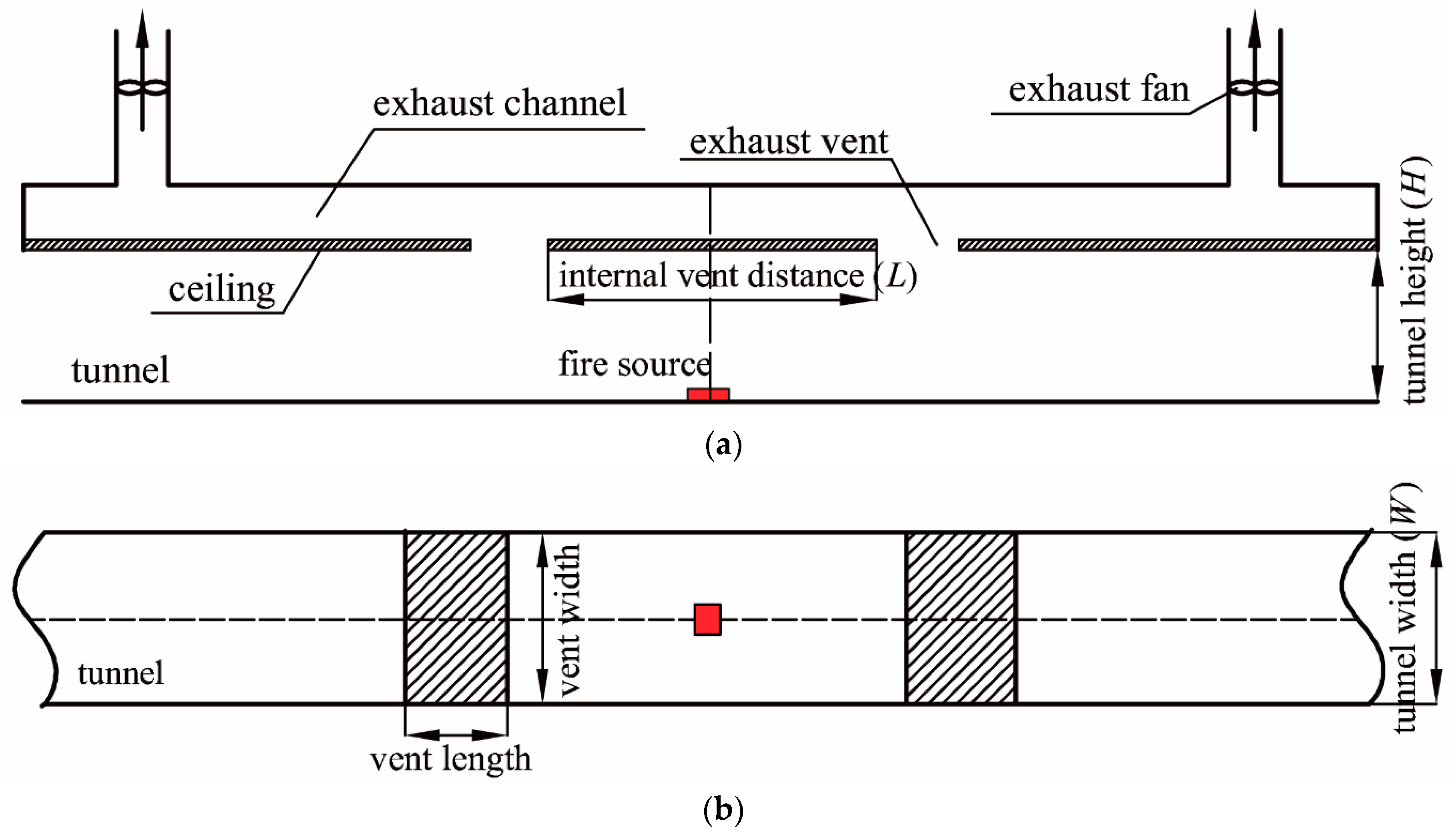
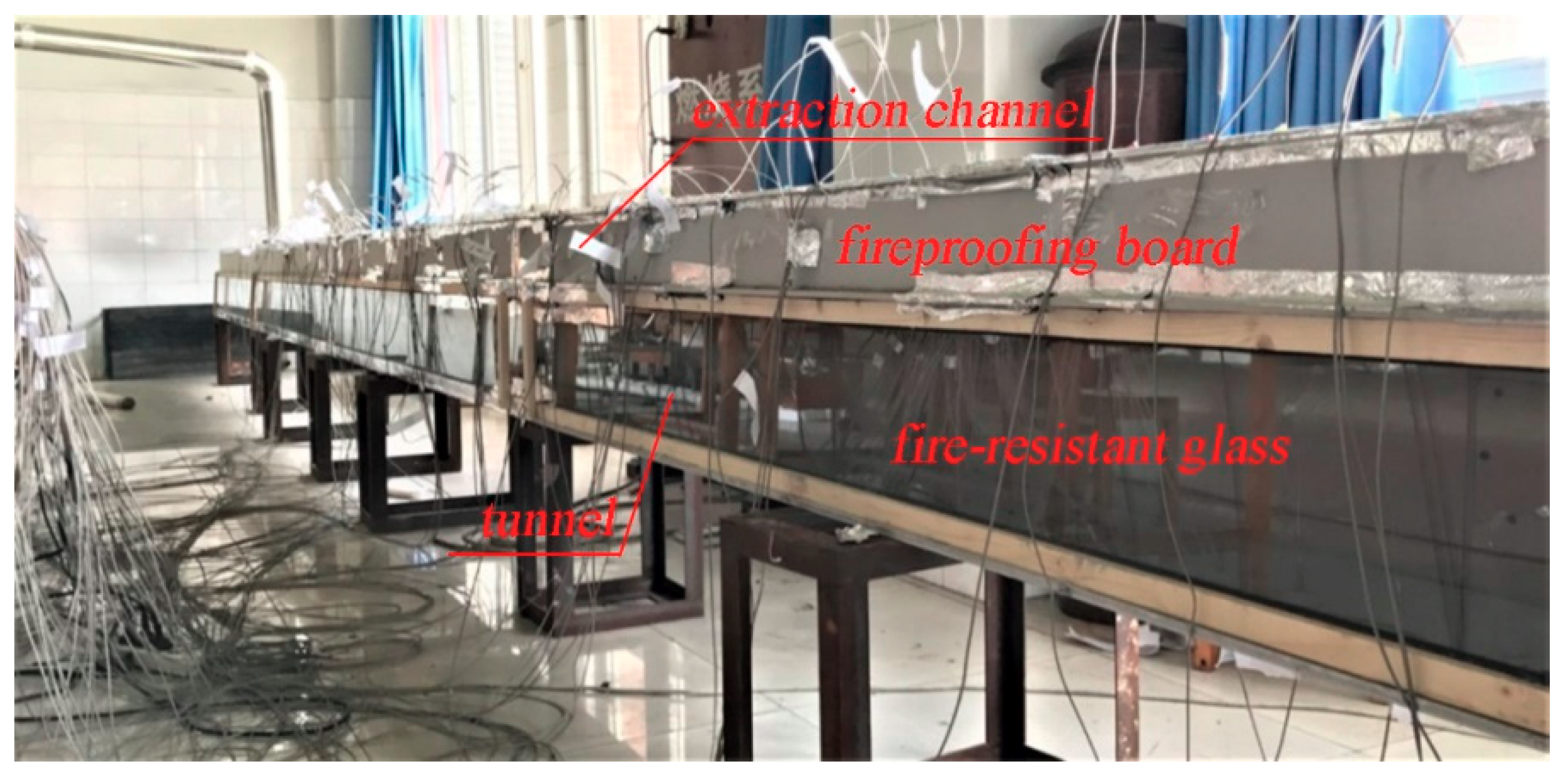
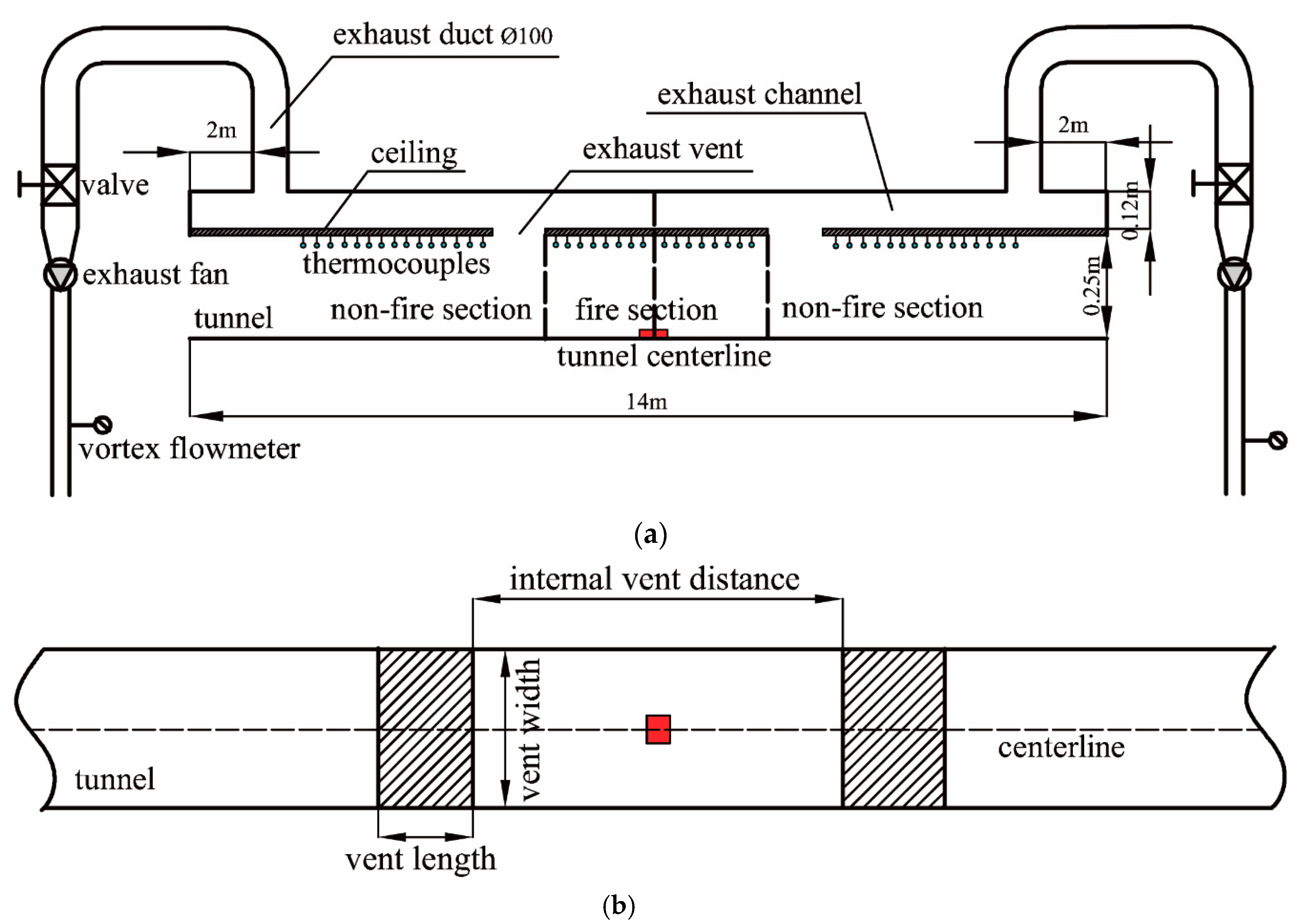
2.1. Experimental Set-Up
2.2. Fire Load
2.3. Experimental Conditions
3. Experimental Results and Discussion
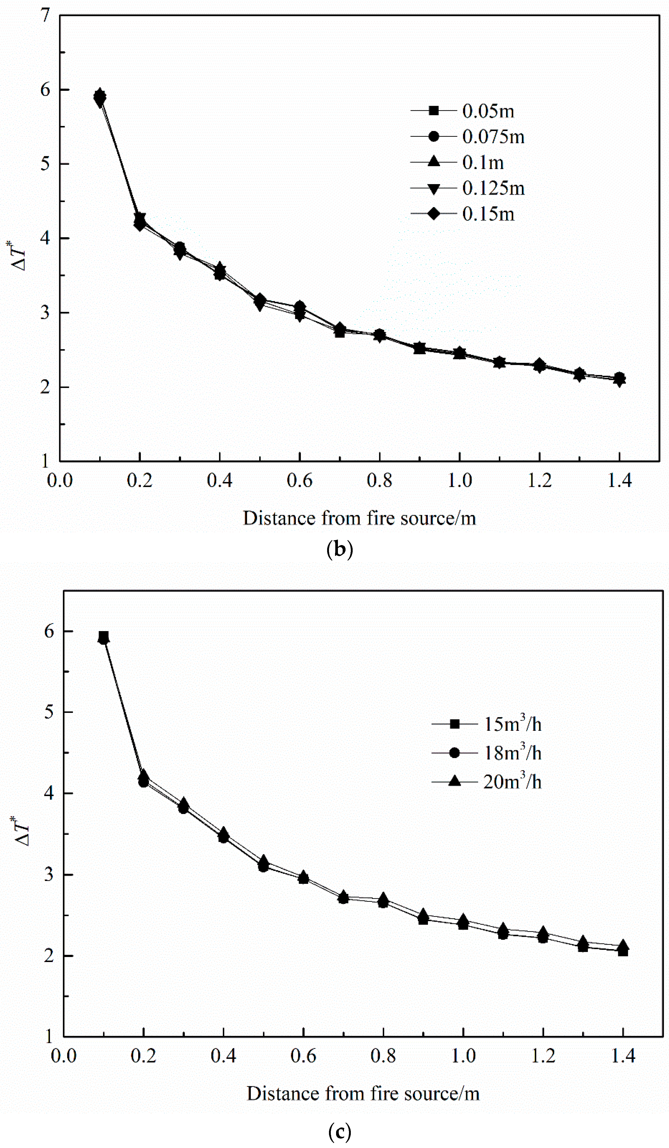
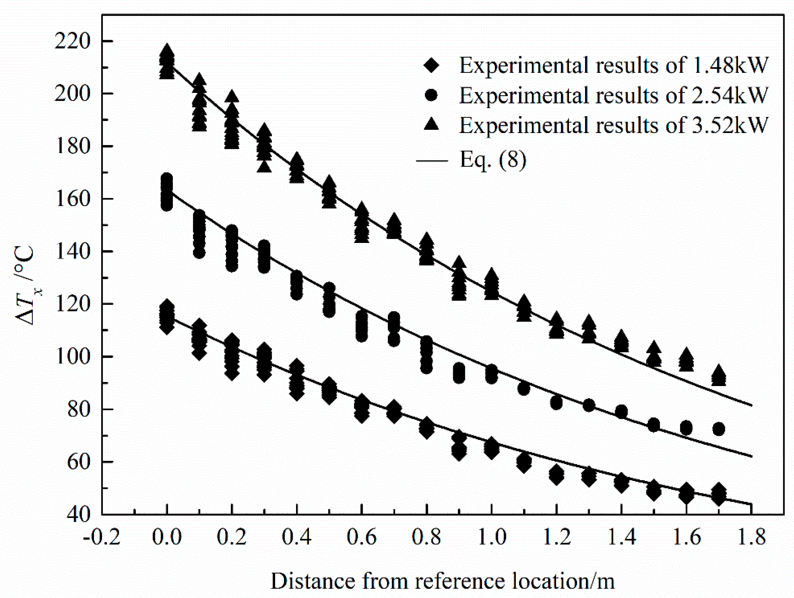
3.1. Longitudinal Temperature Decay
3.2. Temperature Distribution Below the Ceiling
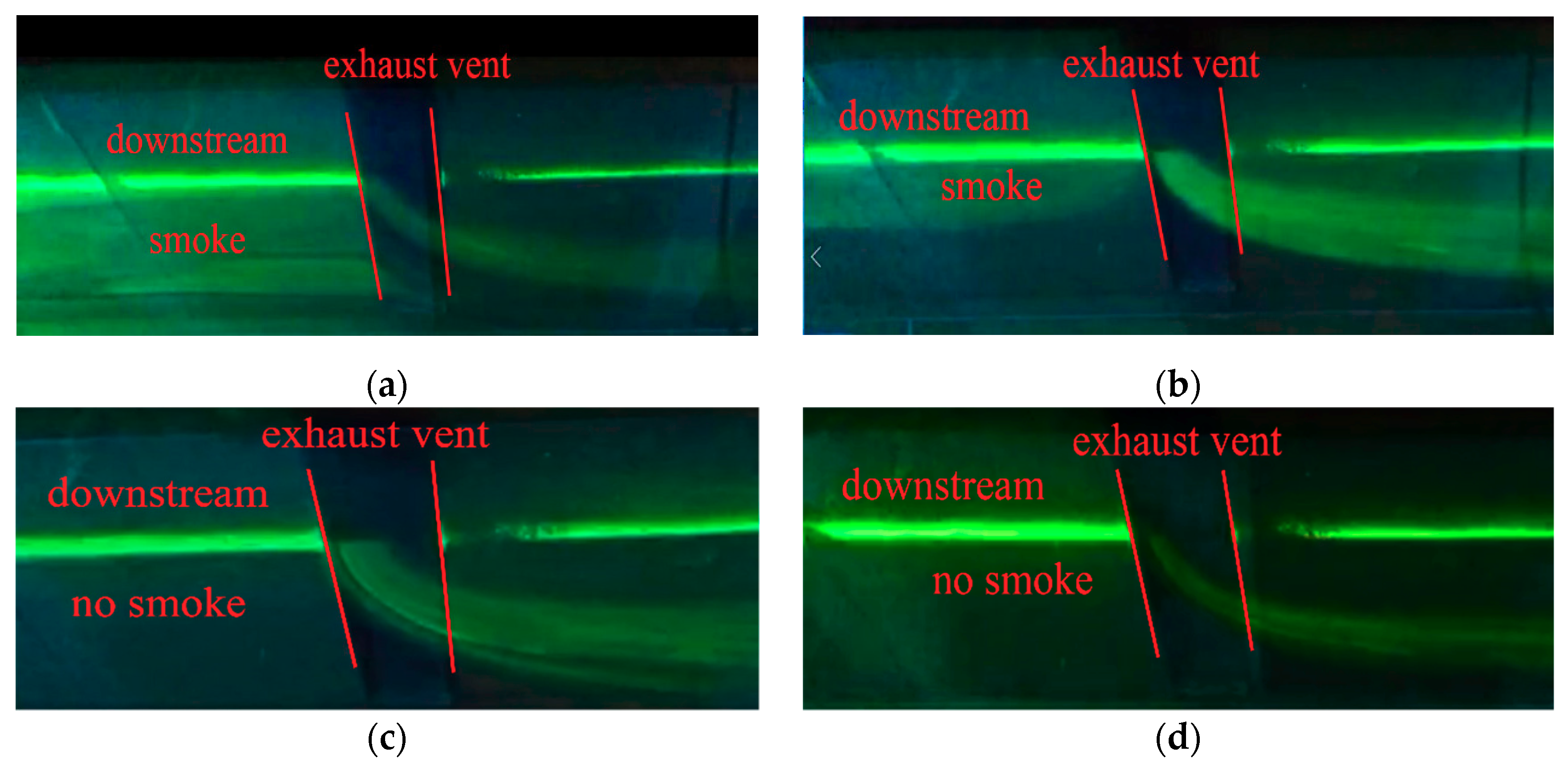
3.3. Critical Exhaust Volumetric Flow Rate
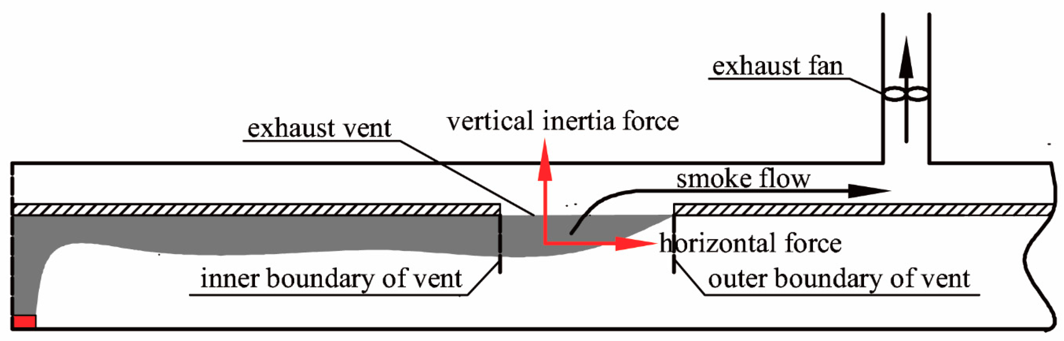
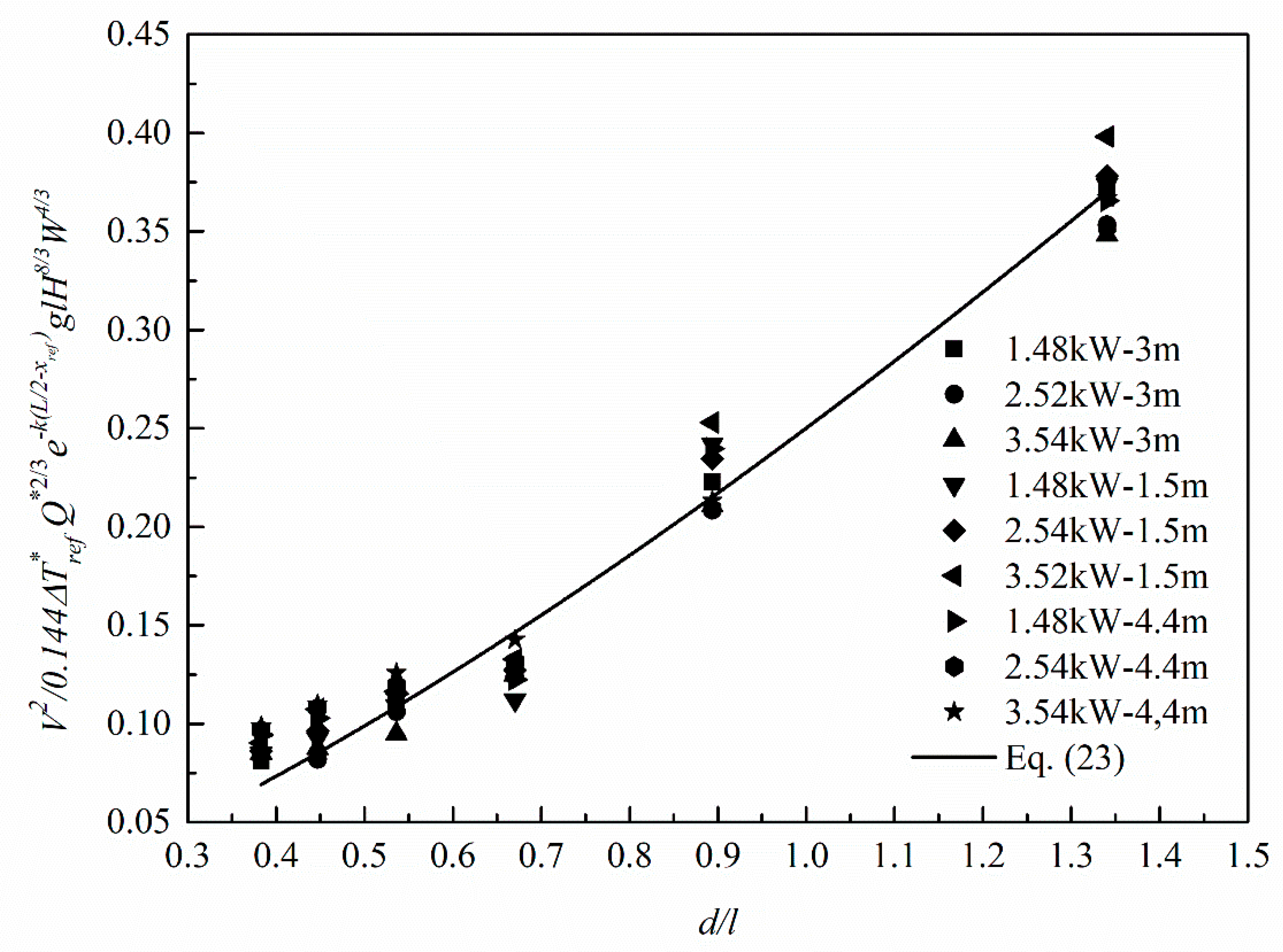
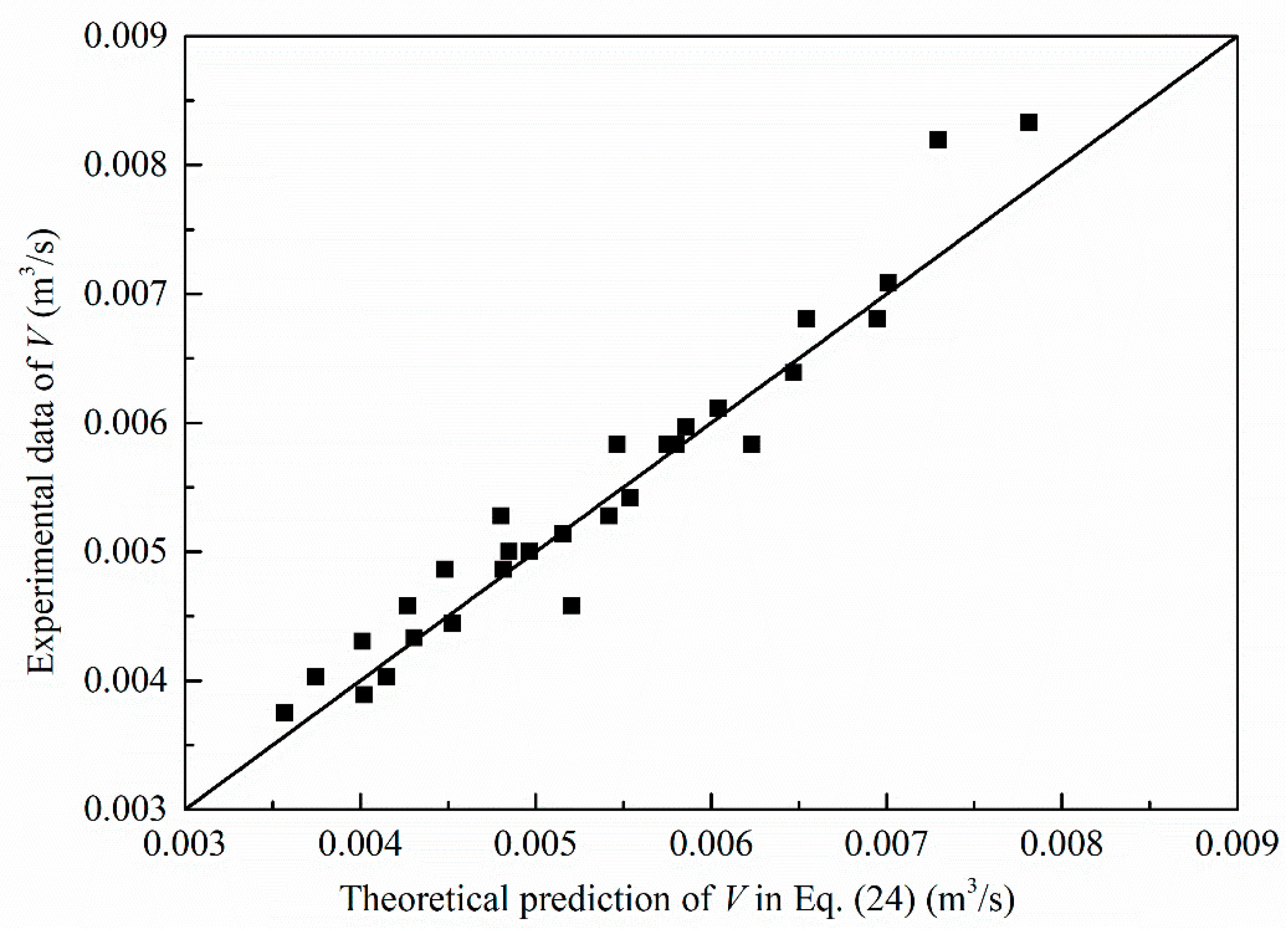
4. Theoretical Prediction for the Critical Exhaust Volumetric Flow Rate
5. Conclusions
Author Contributions
Funding
Acknowledgments
Conflicts of Interest
Nomenclature
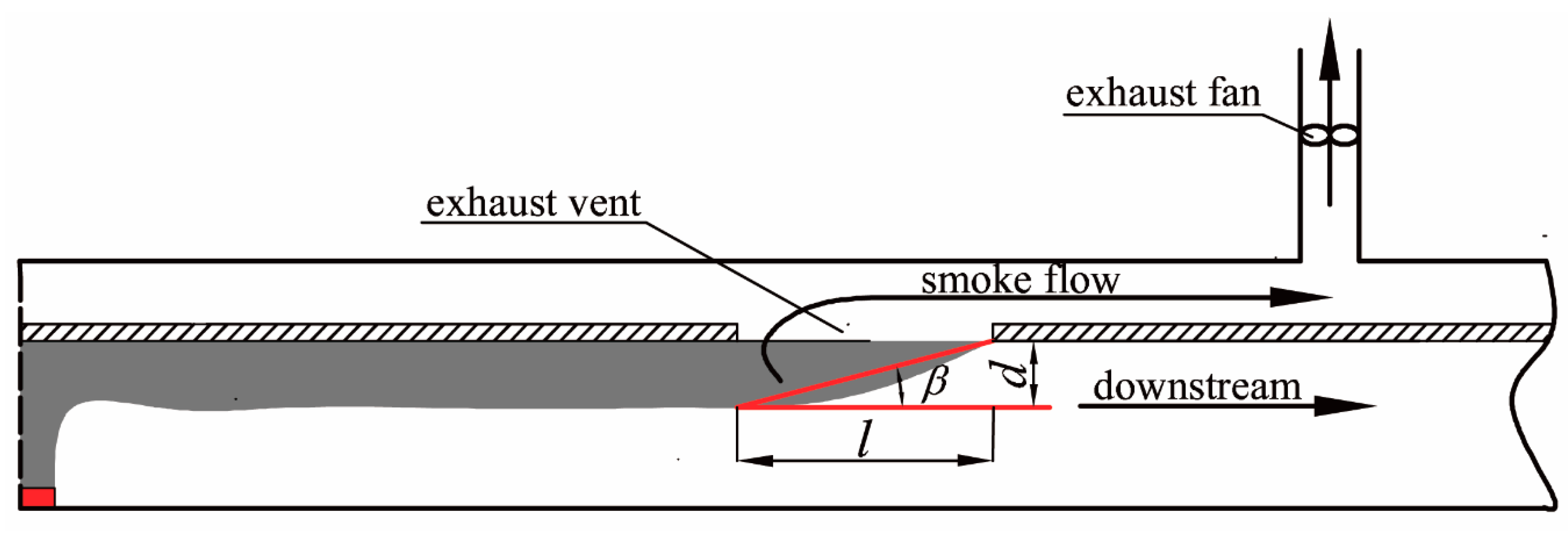
| d | smoke layer thickness (m) |
| Fi | vertical inertia force (N) |
| Fb | horizontal force (N) |
| g | gravity acceleration (m/s2) |
| H | tunnel height (m) |
| k | decay coefficient (m−1) |
| L | internal distance between two extraction vents (m) |
| l | extraction vent length (m) |
| T0 | ambient temperature (K) |
| Tx | smoke temperature (K) |
| Tref | reference temperature (K) |
| u | exhaust velocity (m/s) |
| V | critical exhaust volumetric flow rate of vent (m3/s) |
| W | tunnel width (m) |
| w | extraction vent width (m) |
| x | distance from fire location (m) |
| xref | reference location (m) |
| Greek symbols | |
| ρ0 | ambient density (kg/m3) |
| ρe | density of exhausted smoke (kg/m3) |
| ρb | density of smoke underneath the extraction vent (kg/m3) |
| Δ | difference property between smoke and ambient |
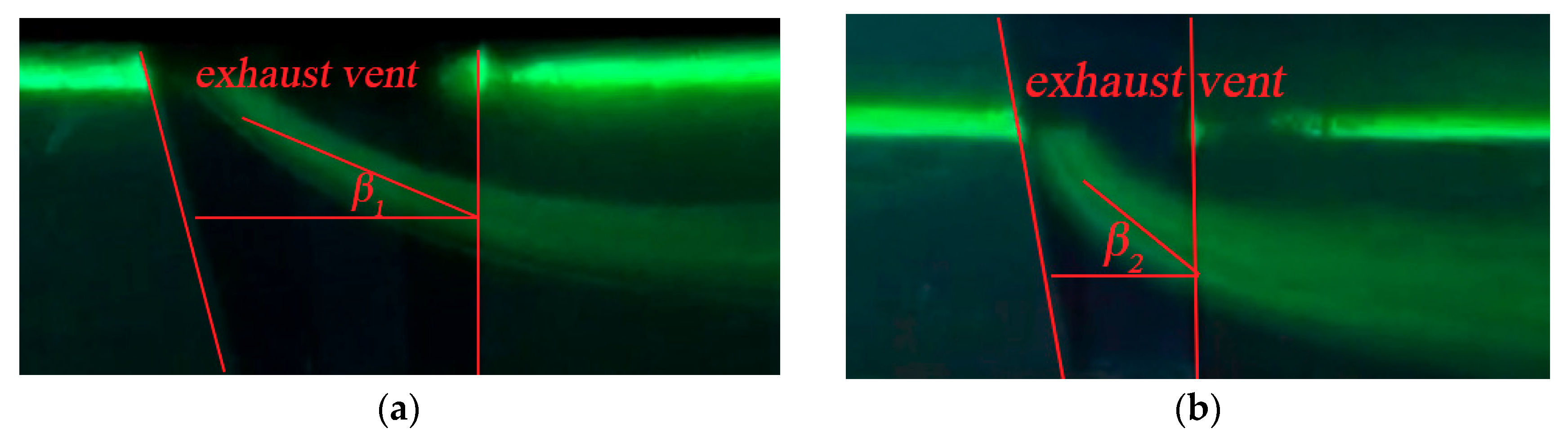
| β | inclined angle |
| α | ratio of small-scale to full-scale |
| Subscript | |
| f | full-scale property |
| m | reduced-scale property |
References
- Ingason, H.; Li, Y.Z.; Lönnermark, A. Tunnel Fire Dynamics; Springer: Berlin, Germany, 2014. [Google Scholar]
- Beard, A.N. Fire safety in tunnels. Fire Saf. J. 2009, 44, 276–278. [Google Scholar] [CrossRef]
- Drenda, J.; Domagała, L.; Musioł, D.; Pach, G.; Różański, Z. An analysis of selected jet fans used in chambers of KGHM mines with respect to the air stream range. Tunn. Undergr. Space Technol. 2018, 82, 303–314. [Google Scholar] [CrossRef]
- Król, M.; Król, A.; Koper, A.; Wrona, P. The influence of natural draught on the air flow in a tunnel with longitudinal ventilation. Tunn. Undergr. Space Technol. 2019, 85, 140–148. [Google Scholar] [CrossRef]
- Thomas, P. The Movement of Buoyant Fluid against a Stream and the Venting of Underground Fires; Fire Research Station: Boreham Wood, UK, 1958. [Google Scholar]
- Oka, Y.; Atkinson, G.T. Control of smoke flow in tunnel fires. Fire Saf. J. 1995, 25, 305–322. [Google Scholar] [CrossRef]
- Bakar, M.; Wu, Y. Control of smoke flow in tunnel fires using longitudinal ventilation systems—A study of the critical velocity. Fire Saf. J. 2000, 35, 363–390. [Google Scholar]
- Carvel, R.; Beard, A.; Jowitt, P. The influence of longitudinal ventilation systems on fires in tunnels. Tunn. Undergr. Technol. 2001, 16, 3–21. [Google Scholar] [CrossRef]
- Kunsch, J. Simple model for control of fire gases in a ventilated tunnel. Fire Saf. J. 2002, 37, 67–81. [Google Scholar] [CrossRef]
- Li, Y.Z.; Lei, B.; Ingason, H. Study of critical velocity and back layering length in longitudinally ventilated tunnel fires. Fire Saf. J. 2010, 45, 361–370. [Google Scholar] [CrossRef]
- Li, Y.Z.; Lei, B.; Ingason, H. The maximum temperature of buoyancy-driven smoke flow beneath the ceiling in tunnel fires. Fire Saf. J. 2011, 46, 204–210. [Google Scholar] [CrossRef]
- Vauquelin, O.; Mégret, O. Smoke extraction experiments in case of fire in a tunnel. Fire Saf. J. 2002, 37, 525–533. [Google Scholar] [CrossRef]
- Vauquelin, O.; Telle, D. Definition and experimental evaluation of the smoke “confinement velocity” in tunnel fires. Fire Saf. J. 2005, 40, 320–330. [Google Scholar] [CrossRef]
- Lin, C.-J.; Chuah, Y.K. A study on long tunnel smoke extraction strategies by numerical simulation. Tunn. Undergr. Technol. 2008, 23, 522–530. [Google Scholar] [CrossRef]
- Ingason, H.; Li, Y.Z. Model scale tunnel fire tests with point extraction ventilation. J. Fire Prot. Eng. 2011, 21, 5–36. [Google Scholar] [CrossRef]
- Zhu, H.; Shen, Y.; Yan, Z.; Guo, Q.; Guo, Q. A numerical study on the feasibility and efficiency of point smoke extraction strategies in large cross-section shield tunnel fires using CFD modeling. J. Loss Prev. Process. Ind. 2016, 44, 158–170. [Google Scholar] [CrossRef]
- Mei, F.; Tang, F.; Ling, X.; Yu, J. Evolution characteristics of fire smoke layer thickness in a mechanical ventilation tunnel with multiple point extraction. Appl. Therm. Eng. 2017, 111, 248–256. [Google Scholar] [CrossRef]
- Tang, F.; Cao, Z.; Palacios, A.; Wang, Q. A study on the maximum temperature of ceiling jet induced by rectangular-source fires in a tunnel using ceiling smoke extraction. Int. J. Therm. Sci. 2018, 127, 329–334. [Google Scholar] [CrossRef]
- Hu, L.; Chen, L.; Tang, W. A global model on temperature profile of buoyant ceiling gas flow in a channel with combining mass and heat loss due to ceiling extraction and longitudinal forced air flow. Int. J. Heat Mass Transf. 2014, 79, 885–892. [Google Scholar] [CrossRef]
- Chen, L.; Hu, L.; Zhang, X.; Zhang, X.; Zhang, X.; Yang, L. Thermal buoyant smoke back-layering flow length in a longitudinal ventilated tunnel with ceiling extraction at difference distance from heat source. Appl. Therm. Eng. 2015, 78, 129–135. [Google Scholar] [CrossRef]
- Tanaka, F.; Majima, S.; Kato, M.; Kawabata, N. Performance validation of a hybrid ventilation strategy comprising longitudinal and point ventilation by a fire experiment using a model-scale tunnel. Fire Saf. J. 2015, 71, 287–298. [Google Scholar] [CrossRef]
- Quintiere, J.G. Scaling applications in fire research. Fire Saf. J. 1989, 15, 3–29. [Google Scholar] [CrossRef]
- Karlsson, B.; Quintiere, J.G. Enclosure Fire Dynamics; CRC Press: Boca Raton, FL, USA, 2000. [Google Scholar]
- Kunsch, J.P. Critical velocity and range of a fire-gas plume in a ventilated tunnel. Atmos. Environ. 1999, 33, 13–24. [Google Scholar] [CrossRef]
- Ji, J.; Zhong, W.; Li, K.Y.; Shen, X.B.; Zhang, Y.; Huo, R. A simplified calculation method on maximum smoke temperature under the ceiling in subway station fires. Tunn. Undergr. Space Technol. 2011, 26, 490–496. [Google Scholar] [CrossRef]
- Hu, L.H.; Huo, R.; Chow, W.K.; Wang, H.B.; Yang, R.X. Decay of buoyant smoke layer temperature along the longitudinal direction in tunnel fires. J. Appl. Fire Sci. 2004, 13, 53–77. [Google Scholar] [CrossRef]
- Oka, Y.; Oka, H.; Imazeki, O. Ceiling-jet thickness and vertical distribution along flat-ceilinged horizontal tunnel with natural ventilation. Tunn. Undergr. Technol. 2016, 53, 68–77. [Google Scholar] [CrossRef]
- Yuan, Z.Y.; Lei, B.; Kashef, A. Experimental and Theoretical Study for Tunnel Fires with Natural Ventilation. Fire Technol. 2015, 51, 691–706. [Google Scholar] [CrossRef]
- Heskestad, G. “Fire Plumes,” SFPE Handbook of Fire Protection Engineering, 3rd ed.; National Fire Protection Association: Quincy, MA, USA, 2002. [Google Scholar]
- Chow, W.K.; Gao, Y.; Zhao, J.; Dang, J.; Chow, C.L.; Miao, L. Smoke movement in tilted tunnel fires with longitudinal ventilation. Fire Saf. J. 2015, 75, 14–22. [Google Scholar] [CrossRef]


| Pool No. | Pool Size/m | Mass Burning Rate g/(s cm2) | HRR in Model Scale/kW | HRR in Full Scale/MW |
|---|---|---|---|---|
| 1 | 0.074 0.074 | 0.00136 | 1.48 | 2.6 |
| 2 | 0.094 0.094 | 0.00144 | 2.54 | 4.5 |
| 3 | 0.115 0.115 | 0.00134 | 3.52 | 6.3 |
| Test No. | HRR (kW) | Length of Extraction Vent (m) | Distance between Extraction Vents (m) | Exhaust Volumetric Flow Rate (m3/h) |
|---|---|---|---|---|
| 1–5 | 1.48 | 0.05 | 1.5 | 18/19.2/20/21/21.5 |
| 6–9 | 0.05 | 3.0 | 15/17.5/18/18.5 | |
| 10–12 | 0.05 | 4.4 | 14.5/15/15.5 | |
| 13–15 | 0.075 | 1.5 | 19.9/20.5/21 | |
| 16–20 | 0.075 | 3.0 | 15/15.5/16/16.5/17 | |
| 21–23 | 0.075 | 4.4 | 14/14.5/15 | |
| 24–27 | 0.10 | 1.5 | 15.3/16/16.5/18 | |
| 28–33 | 0.10 | 3.0 | 10/12.2/14/14.5/15/15.6 | |
| 34–38 | 0.10 | 4.4 | 12/12.5/13/13.5/14.5 | |
| 39–41 | 0.125 | 3.0 | 14.5/15/15.5 | |
| 42–45 | 0.15 | 3.0 | 10.4/13/13.6/14 | |
| 46–50 | 2.54 | 0.05 | 1.5 | 22/24/24.9/25.5/26 |
| 51–55 | 0.05 | 3.0 | 15/18/19/20/21 | |
| 56–57 | 0.05 | 4.4 | 18.5/19 | |
| 58–60 | 0.075 | 1.5 | 24/24.5/25 | |
| 61–64 | 0.075 | 3.0 | 17.5/18/18.5/19 | |
| 65–67 | 0.075 | 4.4 | 17/17.5/18 | |
| 68–70 | 0.10 | 1.5 | 20/20.5/21 | |
| 71–75 | 0.10 | 3.0 | 15/16.5/17/17.5/18.5 | |
| 76–78 | 0.10 | 4.4 | 15/16/16.5 | |
| 79–82 | 0.125 | 3.0 | 18/18.5/19/19.6 | |
| 83–86 | 0.15 | 3.0 | 15/17.1/17.5/18 | |
| 87–90 | 3.52 | 0.05 | 1.5 | 27.7/29/30/30.5 |
| 91–95 | 0.05 | 3.0 | 15/20/21.5/22/23 | |
| 96–98 | 0.075 | 1.5 | 29.5/30/30.5 | |
| 99–102 | 0.075 | 3.0 | 20/21/21.5/22 | |
| 103–107 | 0.10 | 1.5 | 22/23/24/24.5/25 | |
| 108–112 | 0.10 | 3.0 | 19.5/20/20.5/21/22 | |
| 113–116 | 0.125 | 3.0 | 19.5/20/20.5 |
| HRR (kW) | Length of Extraction Vent (m) | Internal Distance between Vents (m) | Measured Critical Exhaust Volumetric Flow Rate (m3/h) |
|---|---|---|---|
| 1.48 | 0.05 | 1.5 | 21.5 |
| 0.05 | 3.0 | 18.0 | |
| 0.05 | 4.4 | 15.5 | |
| 0.075 | 1.5 | 21.0 | |
| 0.075 | 3.0 | 16.0 | |
| 0.075 | 4.4 | 14.5 | |
| 0.10 | 1.5 | 16.5 | |
| 0.10 | 3.0 | 15.6 | |
| 0.10 | 4.4 | 13.5 | |
| 0.125 | 3.0 | 14.5 | |
| 0.15 | 3.0 | 14.0 | |
| 2.54 | 0.05 | 1.5 | 25.5 |
| 0.05 | 3.0 | 21.0 | |
| 0.05 | 4.4 | 19.0 | |
| 0.075 | 1.5 | 24.5 | |
| 0.075 | 3.0 | 19.0 | |
| 0.075 | 4.4 | 17.5 | |
| 0.10 | 1.5 | 21.0 | |
| 0.10 | 3.0 | 18.5 | |
| 0.10 | 4.4 | 16.5 | |
| 0.125 | 3.0 | 18.0 | |
| 0.15 | 3.0 | 17.5 | |
| 3.52 | 0.05 | 1.5 | 30.0 |
| 0.05 | 3.0 | 23.0 | |
| 0.075 | 1.5 | 29.5 | |
| 0.075 | 3.0 | 22.0 | |
| 0.10 | 1.5 | 24.5 | |
| 0.10 | 3.0 | 19.5 | |
| 0.125 | 3.0 | 19.5 |
© 2019 by the authors. Licensee MDPI, Basel, Switzerland. This article is an open access article distributed under the terms and conditions of the Creative Commons Attribution (CC BY) license (http://creativecommons.org/licenses/by/4.0/).
Share and Cite
Zhao, P.; Yuan, Z.; Yuan, Y.; Yu, N.; Yu, T. A Study on Ceiling Temperature Distribution and Critical Exhaust Volumetric Flow Rate in a Long-Distance Subway Tunnel Fire with a Two-Point Extraction Ventilation System. Energies 2019, 12, 1411. https://doi.org/10.3390/en12081411
Zhao P, Yuan Z, Yuan Y, Yu N, Yu T. A Study on Ceiling Temperature Distribution and Critical Exhaust Volumetric Flow Rate in a Long-Distance Subway Tunnel Fire with a Two-Point Extraction Ventilation System. Energies. 2019; 12(8):1411. https://doi.org/10.3390/en12081411
Chicago/Turabian StyleZhao, Peng, Zhongyuan Yuan, Yanping Yuan, Nanyang Yu, and Tao Yu. 2019. "A Study on Ceiling Temperature Distribution and Critical Exhaust Volumetric Flow Rate in a Long-Distance Subway Tunnel Fire with a Two-Point Extraction Ventilation System" Energies 12, no. 8: 1411. https://doi.org/10.3390/en12081411
APA StyleZhao, P., Yuan, Z., Yuan, Y., Yu, N., & Yu, T. (2019). A Study on Ceiling Temperature Distribution and Critical Exhaust Volumetric Flow Rate in a Long-Distance Subway Tunnel Fire with a Two-Point Extraction Ventilation System. Energies, 12(8), 1411. https://doi.org/10.3390/en12081411