Abstract
A novel high-voltage powerline inspection system was investigated, which consists of the cooperated ground vehicle and drone. The ground vehicle acts as a mobile platform that can launch and recycle the drone, while the drone can fly over the powerline for inspection within limited endurance. This inspection system enables the drone to inspect powerline networks in a very large area. Both vehicle’ route in the road network and drone’s routes along the powerline network have to be optimized for improving the inspection efficiency, which generates a new Two-Layer Point-Arc Routing Problem (2L-PA-RP). Two constructive heuristics were designed based on “Cluster First, Route Second” and “Route First, Split Second”. Then, local search strategies were developed to further improve the quality of the solution. To test the performance of the proposed algorithms, different-scale practical cases were designed based on the road network and powerline network of Ji’an, China. Sensitivity analysis on the parameters related to the drone’s inspection speed and battery capacity was conducted. Computational results indicate that technical improvement on the inspection sensor is more important for the cooperated ground vehicle and drone system.
1. Introduction
Economic expansion and development of urbanization have led to an enormous increase in demand for electricity consumption, requiring the high reliability of the power supply. As the connection between the electricity generation node and customer nodes, high-voltage power transmission lines have an important role in the overall performance of the electrical network. Most powerlines are far away from main roads and household centers for considerations of safety, environment protection, and cost saving. Traditionally, the inspection of high-voltage powerlines is mainly conducted by manned helicopters or foot patrol, which is inefficient and expensive, sometimes even presenting heavy workload and unknown dangers for inspection technicians. When powerlines cross forests, rivers or other geographic circumstances unreachable for manual inspection, this work becomes much more difficult. Thus, it is one of the most important works in power management to find more effective and economic ways for powerline inspection.
In recent years, drone-assisted powerline inspection has been identified as a viable alternative method, due to the rapid development of automation and artificial intelligence technologies [1,2]. The advent of airborne sensors, such as thermal infrared imager and visible light camera, allows the drone to detect common faults, including transmission line fault, loss of line equipment and damage of transmission tower. Without the limitation of road distribution and geographical issues, the drone can realize the autonomous inspection along the powerlines, which significantly reduces the time and capital cost of the inspection. Furthermore, there is no casualty risk for technicians, as they do not need to directly face the complex environment or perform dangerous operations. Given these advantages, many companies have tried to apply drone for powerline inspection. In November 2018, Ameren successfully utilized a drone for a 60-mile transmission line inspection [3]. Another company in America, Indiana Michigan Power (I&M), has achieved drone inspection on transmission lines in Randolph County since January 2019 [4]. In china, more and more enterprises in power industry have used inspection drones [5]. An intelligent inspection system is developed on the small drone equipped with HD camera and infrared thermal imager, which has been successfully applied on 500 kV and 220 kV powerlines in some provinces such as Shandong and Gansu.
However, some obstacles prevent the wide adoption of the drone-assisted powerline inspection. Sometimes, the drone needs to hover in some crucial areas or fly at low altitude for closer inspection, which means small-scale drones are more versatile for accurate detection. However, with limited endurance, small drones have difficulty inspecting long distances and for a long time. For most drones, their capacities of battery power are not sufficient for long-term inspection mission. Second, the establishing cost for the control and communication center is too expensive, and it is impractical to construct many ground base stations in the powerline-covered area. Furthermore, it would cause the failure of communications as well as much waste of time and energy when the drone leaves the station to inspect powerlines too far away. To overcome these practical difficulties, a cooperated ground vehicle and drone system for powerline inspection is presented in Figure 1, which introduces a novel powerline inspection mode.
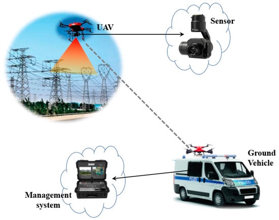
Figure 1.
Illustration of powerline inspection by the cooperated ground vehicle and drone system.
The powerline inspecting system is formed by the cooperated ground vehicle and drone. Equipped with the control and communication system, the ground vehicle serves as a mobile base station. The ground vehicle can drive to a location near the powerline in the road network and then launch the drone. When the drone inspects with airborne sensors along the powerline, the technicians on the vehicle can control the flight of drone and process the data and images captured by the drone. Simultaneously, the ground vehicle keeps moving forward to the next rendezvous close to the powerline and recycles the drone before it runs out of energy. The operations for charging or replacing the drone battery can be conducted on the vehicle, and then the drone can rapidly perform inspection again. This new mode has several notable advantages. Initially, acting as a moving station, the ground vehicle can offset the drone’s disadvantage on limited endurance and enable the drone to inspect powerlines in a very large area. Second, the ground vehicle can move forward to pick up the drone, which shortens the drone’s flight distance and greatly improves the inspection efficiency. Thirdly, with shorter distance between the vehicle and the drone, communications are more stable, which facilitates the effective control of the drone and timely analysis of the collected data.
Although the new powerline inspection mode by cooperated vehicle and drone is efficient both in time and cost, it brings many new challenges on the route planning of the vehicle and drone. As displayed in Figure 2, the vehicle travels on the road network while the drone flies along the high-voltage power transmission line, which causes a novel Two-Layer Point-Arc Routing Problem (2L-PA-RP). The road network for the ground vehicle is in the lower layer, where there are a set of potential parking nodes for launching and recycling the drone. The network of the high-voltage powerlines is in the upper layer. The drone is launched from the vehicle at one parking node, flies to the powerline, conducts inspection along the line and then returns to the vehicle at another parking node before the battery powers off. The routing planning for the vehicle and the drone is to optimize the locations (parking nodes) for launching/recycling the drone, vehicle’s route on the road network for visiting these nodes, and drone’s routes on the powerline network to minimize the completion time or the cost for inspecting all the powerlines.
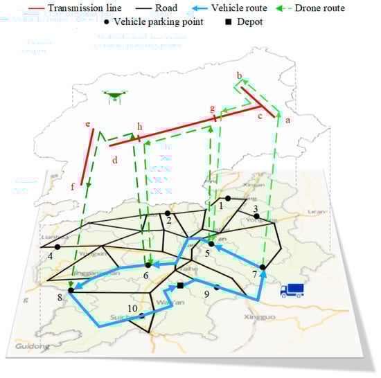
Figure 2.
Illustration of the two-layer point-arc routing problem.
Motivated by the adaption of new technologies and inspection tool (drone) in power delivery industry, a novel powerline inspection system with cooperated vehicle and drone is proposed. A new two-layer point-arc routing problem is generated due to the application of this new inspection system, and a description model to illustrate the problem clearly is established. The 2L-PA-RP integrates two classical routing problems, the Travelling Salesman Problem with visiting node selection (the lower layer subproblem) and the Arc Routing Problem (the upper layer subproblem), both of which are NP-Hard problems. Besides, the interaction between the two layers has to be considered. Spatially, the rendezvous nodes for two vehicles are located on both truck and drone routes. In the temporal domain, the truck is supposed to arrive at the rendezvous node and recycle the drone before the drone powers off. Thus, the ground vehicle’s route and moving should cooperate with the drone’s routes and flying in the whole process, which makes the problem more complex. Furthermore, although the potential parking nodes are predefined, the nodes where the drone flies into or out of the powerline network are uncertain and need to be optimized. Since the drone can enter or leave the upper layer at any node, this problem is more difficult to solve than the traditional two-echelon routing problem. Due to the complexity of the problem, two constructive heuristics are designed, and the local search strategies are applied to improve the solutions obtained by constructive heuristics. Three practical instances with different sizes, based on the practical powerline network and road network in Ji’an, a city in China were used to test the performance of the algorithms. Sensitivity analysis for critical parameters was conducted for finding their influence on the efficiency of the novel cooperated inspection system.
2. Literature Review
Electricity production and distribution has always been an area of immense concern. Nowadays, with rapid increase of energy demand, many researchers have contributed to the planning and expansion of power system [6,7,8,9]. Sarıca et al. [10] developed a model to investigate the implications of the power market on profits, prices, availability and supply security, which also entails a critical challenge to power transmission line inspection.
It is an important research topic for researchers to find more economical and efficient ways for power system inspection. In 1991, Tokyo Electric Power Company proposed a mobile robot for detecting the 66-KV fiber-optic overhead ground wires (OPGW), which can run on the OPGW and negotiate obstacles such as counterweights and clamps [11]. Since then, many studies discuss the hardware design and software construction of the inspection robot. Some of this research focuses on the obstacle avoidance of the inspection robot (e.g., [12]). In 2009, Katrasnik et al. [13] conducted a survey on the mobile robots applied in transmission line inspection and discussed the inspection with automated helicopter or flying robots. Another survey [14] also points out that this inspection methoed can improve efficiency and reduce costs, and presents the latest trends for robot transmission. Besides, the corresponding software design, e.g. database environment [15] and detection method through images or videos [16], are also studied. Fan et al. [17] proposed a Multi-Robot Cyber Physical System (MRCPS) for effective monitoring and maintenance.
With the development of remote sensing and artificial intelligence technology, drones present huge application opportunities, especially in reconnaissance missions [18]. Due to their high efficiency and low cost, drones have an important role in the inspection of bridge, cell towers and so on [19,20]. In electricity field, drones have been applied to the inspection for both transmission structure and powerline [21,22]. Various inspection systems are developed based on different kinds of drones. Hrabar et al. [23] developed a platform of autonomous small helicopter and showed that both fixed-wing and rotorcraft UAVs (RUAVs) are suitable for powerline inspection. They also proved that RUAVs are more versatile with the ability of hovering and vertical climbing or descending. Huang et al. [24] focused on the fixed-wing UAV and realized the low-speed low-altitude patrol in suspected locations. Few studies mention large unmanned helicopters, which can schedule multiple sensors to track the power lines automatically [25].
To ensure the accuracy of drone inspection, some algorithms are proposed. Primarily, as drone inspection is based on the images captured by the airborne camera, various classification and recognition algorithms are designed [26,27,28,29,30]. Martinez et al. [26] combined classic computer vision and machine learning for autonomous aerial powerline inspection and localization. To distinguish the transmission line from the natural outdoor environment, a decomposition structure is used in transmission line detection (TLD) algorithm [27]. In addition, spectral-spatial methods are applied [28]. Li et al. developed a pulse coupled neural filter to remove background noise [29]. Furthermore, there is a survey for existing automatic vision-based power line inspection systems [30]. The authors also utilized deep learning in the proposed vision-based powerline inspection concept. There is also research on the risk assessment of the drone in the powerline inspection process [31].
Considering works mentioned above, we can see that almost of the studies are concerned about the hardware design or the flight control for drone inspection. Only two papers discuss the route planning in the inspection problem with drone. One is proposed in 2009, involving the mission planning of the flying robot for powerline inspection [32]. It develops a basic planning system to directly give the inspection scheme, including checking order, space path and flight trajectory. Since it mainly focuses on the robot control, it does not pay much attention to the optimization of path planning. The other paper studies the drone inspection for electric transmission towers [33]. Three performance ratios are considered in the optimization: flight time, image quality, and tower coverage. A particle swarm optimization (PSO) based algorithm and a simulated annealing (SA) based algorithm are designed to solve the problem. With only transmission towers involved and without transmission lines, the problem is modeled as a Traveling Salesman Problem.
From the above review, the inspection problem of power transmission line with cooperated ground vehicle and drone has not been studied. It has been proved this novel system can improve the work efficiency in reconnaissance missions [34] and can be employed for powerline inspection. The newly generated two-layer point-arc routing problem for the cooperated ground vehicle and drone is important for efficiently utilizing this novel system, which has not been investigated. Therefore, this paper studies this new problem and develops an efficient approach to optimize the routes for both the ground vehicle and drone.
3. Problem Description and Model Development
3.1. Problem Description
In the two-layer point-arc routing problem (2L-PA-RP), the vehicle travels on the road network while the drone flies along the transmission line. Ground vehicle can only stop at the predefined parking nodes. The endurance capacity of the drone is limited and known. The problem aims to optimize both drone routes along the powerlines and vehicle routes on the road network, involving the selection of parking locations to minimize the completion time for the whole powerline inspection task. Figure 3 shows the aerial view of the example 2L-PARP in Figure 2, which contains four powerline arcs (<a,c>, <b,c>, <c,d>, and <e,f>) and 10 potential parking nodes. Arc <e,f> is not connected with other arcs, and this situation appears when different segments represent different-voltage powerlines. The route traveled by the ground vehicle is the lower layer, represented as blue solid lines, whereas the drone routes, depicted as green dashed lines, belong to the upper layer.
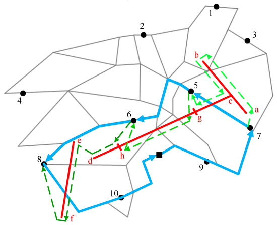
Figure 3.
Aerial view of a solution for the example in Figure 2.
More formally, the 2L-PA-RP can be described as follows. Two undirected graphs are defined: GG = (VG, EG) for the road network and GD = (VD, ED) for the powerline network. VG is the set of all parking nodes and VD is the set of all the vertices in the powerline network. EG is the set of edges on the road network while ED contains the edges that can be traveled by the drone.
Specifically, the ground vehicle can travel with the speed of vg only on the edges in EG, which are all located in the lower layer. Each edge eg EG can be represented by < i, j > (i, j VG), and its distance can be calculated as dij1, which is not the Euler distance but the actual travelling distance for the ground vehicle on the road network.
As for the upper layer, let ER ED be the set of edges required to be inspected, which is {<a, c>, <b, c>, <c, d>, <e, f>} in Figure 3. Represented by < i, j > (i, j VD), the linear distance of any required edge er ER can be calculated as dij2, and the edge is said to be served if and only if the drone traverses the arc for one time. Since the drone can fly into or out of the powerline at any node, each edge er ER can be served in one flight or several flights. For instance, Edges <a,c> and <b,c> are only included in one drone route while Edge <c,d> is divided into three segments: <c, g> inspected in the first flight, <g,h> inspected in the second flight and <h,d> inspected in the third flight. In one drone route, there are two flight modes, regular flight and inspection flight. The drone can fly quickly from the vehicle to the node on the transmission line (e.g., 7→a) or from one powerline node to another (e.g., b→c), and inspect the powerline with airborne sensors at a slow speed (e.g., a→b). We denote the inspection speed as vd1 and the regular flight speed as vd2 (vd1 ≤ vd2). Besides, the airborne sensors would not work and stay in standby state when the drone is in regular flight. Thus, the power consumption rate of the drone per unit time during inspection, denoted as p1, is assumed to be higher than that during regular flight, p2 (p1 > p2). The more detailed calculation for the energy consumption process of the drone is presented in Section 3.2. In addition, since in this problem we utilize the ground vehicle that equips automated systems for launching, recycling and exchanging battery for the drone, it would take only a few seconds for launching, recycling and preparing for the next flight. Thus, compared to the endurance time, over 20 min, the launching and recycling time of the drone can be neglected.
To represent the powerline segments, we introduce a variable λijm into the edge < i, j > (i, j VD), representing node m on the edge, among which
For instance, node g can be described as . Thus, each drone flight route can be encoded as an order list s, in which the first number is the departure road node, the last number is the returning road node, and the middle numbers represent the inspection powerline segments, such as s1: {7, a, c, b, c, g, 5}, s2:{5, g, h, 6} and s3:{6, h, e, f, 8} in Figure 3.
Since the ground vehicle must arrive at the end node before the drone, the drone would spend more time on flight sk than the vehicle on the corresponding road route. Let t1(sk) denote the time that the drone finishes the drone flight sk, which also means the completing time for the sub-solution of sk. In some situations, flight sk is not connected with flight sk+1, and the ground vehicle has to recycle the drone at the end node of sk and carry the drone to the start node of sk+1 to launch it. Let t2(sk, sk+1) denote the time that the vehicle travel from the end node of sub-solution sk to the start node of sub-solution sk+1.
A feasible solution for 2L-PA-RP should satisfy the following constraints:
- All the edges of the powerline network must be inspected by the drone, and each edge is visited only once.
- The ground vehicle should start at the deport and return to the deport at end.
- The ground vehicle has to arrive at the parking node before the drone to recycle it in time.
- The drone must return to the truck before its battery is power off.
- The route of the ground vehicle must be successive.
- Each route of the drone must be successive.
The total time of a feasible solution for completing the inspection task can be calculated as follows.
where S is the set of all drone’s routes. The objective of 2L-PA-RP is to find the feasible solution that minimizes the time for completing the inspection of the powerline network.
3.2. Energy Consumption Model of the Drone
When the drone flies from the ground vehicle to the transmission line, or from one transmission line to another, the airborne sensors would stay in the standby state, which can save more energy than that during the inspection. In one drone flight, the inspection time is denoted as t1, and the regular flight time is t2. With the maximum capacity of the drone battery, D, the energy consumption in one drone route must satisfy the constraint:
Since the weight of payload would not be change during the task, we assume that the total weight of the drone with its airborne sensors is G. The flying speed for powerline inspection is denoted as vd1 and the flying speed under regular state is denoted as vd2. According to D’Andrea [35], the powers power consumption rate of the drone per unit time under different states can be calculated as follows.
where is the conversion efficiency of the motor, is the lift ratio, e is the energy loss of the drone battery, and ps is the energy consuming rate of the airborne sensors.
Suppose that the drone flies at a constant speed when inspecting the powerline, and let , which can be calculated with the brand and type of the drone. Similarly, the drone keeps constant speed at the regular flight state. Then, the constraint in Equation (3) can be expressed with inspection distance, d1, and regular flight distance, d2, which is
4. Solution Algorithm
Two NP-Hard problem, TSP (for vehicle route) and ARP (for drone route), are integrated in this problem, and the vehicle’s route and drone’s routes need to cooperate in both spatial and temporal domains. Thus, it is difficult to solve the problem in acceptable time, especially for large size instances. Two constructive heuristics are proposed in this section, which can generate a more feasible solution in short time. The first heuristic is designed based on the idea of “Cluster First, Route Second” (CFRS) while the second one employs the idea of “Route First, Split Second” (RFSS). Then, some local search strategies are developed to further improve the solution obtained by the heuristics.
4.1. Heuristic Based on “Cluster First, Route Second”
The basic idea of “Cluster First, Route Second” is to split the problem into two simpler routing problems: capacitated arc routing problems (CARP) and a variant of traveling salesman problem (TSP). Firstly, all powerlines would be inspected by constructing a set of drone routes under the limitations of the drone’s endurance capacity and the time relationship between the ground vehicle and the drone. Then, a cluster function would be applied to merge some drone routes and generate sub-solutions. Finally, the vehicle route is built by connecting all the sub-solutions, which is solved by CW saving algorithm.
4.1.1. Generating Sub-Solutions
When generating sub-solutions, all powerlines are firstly divided into multiple segments on the basis of inflection nodes (Line 1), such as four transmission line segments (<a,c>, <c,b>, <c,d> and <e,f>) of the example in Figure 3. Then, for each segment, constructing a complete drone route is attempted (Lines 3–5). Specifically, the nearest parking node for each endpoint of the segment would be selected as the launching node or the recycling node (Line 4). If the drone can travel from one nearest road node and return back to the other after inspection without violating the endurance limitation as well as the time relationship between vehicle and drone (Line 5), a feasible drone route would be constructed for this segment (Line 6). If the two constraints cannot be satisfied, the powerline segment would be divided into two equal parts and replaced with two new segments (Line 8). These steps are repeated until all powerlines are inspected (Lines 3–9). Finally, to improve the utilization of the drone, some drone routes would be merged (Line 11), which would finally form the sub-solutions for the whole inspection task. The main algorithm is shown in Algorithm 1.
| Algorithm 1: Generating sub-solutions | |
| 1 | Divide the transmission lines into segments |
| 2 | WHILE (there exist unvisited line segments) DO |
| 3 | Select an unvisited line segment |
| 4 | Find two nearest road nodes as launching node and recycling node |
| 5 | IF drone route can be built without violating the constraints THEN |
| 6 | Construct the drone route |
| 7 | ELSE |
| 8 | Replace the segment with two new segments |
| 9 | END IF |
| 10 | END WHILE |
| 11 | Cluster some drone routes and form sub-solutions |
Take the case in Figure 3 as an example. For segment <a,c>, node 7 is the nearest parking node for both the endpoint a and c. Thus, after verifying the feasibility, the drone takes off from node 7, enters the power grid from endpoint a, and finally returns to the vehicle from endpoint c to node 7 after completing the inspection of the segment <a,c>. For segment <c,b>, the nearest parking nodes for two endpoints are different, which construct a drone route as {7, c, b, 3}. However, for the segment <c,d>, the distance is too long to complete the inspection by one drone route. Therefore, the midpoint h is inserted to replace the old segment <c,d> with two new segments, <c,h> and <h,d>. Then, the same way of generating drone routes is applied on the two new segments. It goes well for the segment <h,d>, which can be inspected in one flight as {6, h, d, 6}. However, for segment <c,h>, after finding nearest parking nodes 7 and 6, the vehicle would spend more time travelling from node 7 to 6 than the time that the drone consumes for the flying route, which means the route {7, c, h, 6} cannot satisfy the time relationship between the drone and the vehicle. Thus, two new drone routes {7, c, g, 5} and {5, g, h, 6} are formed. Finally, 6 drone routes are generated for the example case, which is displayed in Figure 4a.
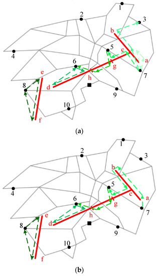
Figure 4.
An illustration of the drone routes for the example case: (a) drone routes before merging; and (b) drone routes after merging.
Algorithm 2 presents the merging operation in detail. For each drone route, all subsequent routes are traversed to find whether there exists a drone route that can be merged feasibly for time saving (Lines 4–8). If the most time-saving drone route can be found (Line 9), then the merging operation is conducted (Line 10), otherwise the cycle is stopped (Line 12). Particularly, since, in the drone route of this problem, the time cost of forward flight is the same with that of reverse flight, which means the drone route is undirected, the forward merging and reverse merging would both be considered in the calculation (Line 6).
| Algorithm 2: Merging drone routes | |
| 1 | m: the number of drone routes |
| 2 | FORi = 1 to m−1 DO |
| 3 | WHILE (1) DO |
| 4 | FOR j = i+1 to m DO |
| 5 | IF drone route i and drone route j can be merged THEN |
| 6 | Calculate the saving time (i, j) |
| 7 | END IF |
| 8 | END FOR |
| 9 | IF exists a drone route that can save time through merging THEN |
| 10 | Merge drone route i with the most saving drone route |
| 11 | ELSE |
| 12 | Break |
| 13 | END IF |
| 14 | END WHILE |
| 15 | END FOR |
Figure 4b shows the result of the example case after merging. Routes {7, a, c, 7}, {7, c, b, 3}, and {7, c, g, 5} are merged into a new drone route {7, a, c, b, c, g, 5}.
4.1.2. Constructing Vehicle Route
After constructing the drone routes, multiple sub-solutions covering the entire power grid are obtained, each of which can be regarded as a target that must be visited by the ground vehicle. However, there are two endpoints for each sub-solution. Since drone routes are all undirected, it would cause different results, depending on which endpoint the vehicle would choose as the start node. Thus, it can be seen as a variant of traveling salesman problem.
CW Saving algorithm [36], which can provide an effective method for solving the TSP problems, is applied to construct the vehicle route. The main procedure is shown in Algorithm 3.
The sub-solutions generated by Algorithm 2 are set as initial input of Algorithm 3. An array for recording the vehicle route would be declared. The first and the last element are both initialized as the depot, and the first sub-solution is added (Line 2). Then, the remaining sub-solutions would be inserted into the array in the labeled order (Line 3). After calculating the added time for every position that each sub-solution can be inserted into the array (Lines 4–6), the position with minimum add time would be chosen (Line 7). Specifically, there are two ways for the vehicle to visit a sub-solution, depending on which endpoint would be selected as the enter node. For example, the vehicle can visit {7, a, c, b, c, g, 5} from node 7 while the opposite direction to enter the sub-solution from node 5 is also feasible. Thus, both directions should be considered when calculating the added cost (time). Finally, a vehicle route is constructed.
| Algorithm 3: Constructing vehicle route | |
| 1 | m: the number of generated sub-solutions |
| 2 | INITIALIZE subsoluArray |
| 3 | FOR tempSubSolu = 2 to m DO |
| 4 | FOR i = 1 to length(subsoluArray)+1 DO |
| 5 | Calculate added time when putting tempSubSolu into subsoluArray at position i |
| 6 | END FOR |
| 7 | Choose the position with minimum add time to insert tempSubSolu |
| 8 | Update the subsoluArray |
| 9 | END FOR |
After constructing the drone routes and the vehicle route, an initial feasible solution can be obtained for the problem. The feasible solution for the example case is illustrated in Figure 5.
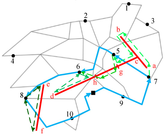
Figure 5.
An illustration of the feasible solution by Cluster First, Route Second (CFRS) for the example case.
4.2. Heuristic Based on “Route First, Split Second”
In the heuristic based on “Route First, Split Second”, a giant drone route for inspecting all the powerlines is firstly found without taking into account the endurance limitations of the drone. Then, the giant drone route is split into sub-solutions to satisfy the constraints of the drone’s endurance capacity and the time relationship between the ground vehicle and drone. Since the sub-solutions have been sorted before, a vehicle route is immediately formed after the splitting process.
4.2.1. Generating a Giant Drone Route
Without considering the endurance constraint of drone, a giant drone route covering all the powerlines is generated through referring to the idea of CW Saving algorithm [36]. After dividing the powerline network into multiple segments and getting the number of powerline segments (Line 1), the first segment would be initialized as the array for recording the visiting order of segments (Line 2). Then, the remaining segments would be inserted into the array in the labeled order (Line 3). Each segment would be attempted to insert into every position in the array, and the corresponding add time would be calculated (Lines 4–6). Specifically, for the segment < i, j > (i, j VD), the forward insertion (from i to j) and reverse insertion (from j to i) would both be considered due to the undirected segment. Then, the segment would be put into the array with the position of minimum adding cost and the corresponding inspection direction (Line 7). Finally, a giant drone route is found. The drone route for the example case is shown in Figure 6, which is {7, a, c, b, c, d, e, f, 8}. The main procedure is shown in Algorithm 4.
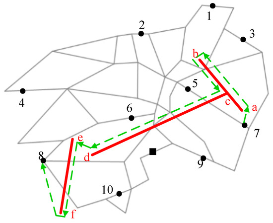
Figure 6.
An illustration of the feasible solution by Route First, Split Second (RFSS) for the example case.
| Algorithm 4: Generating a giant drone route | |
| 1 | m: the number of transmission line segments |
| 2 | INITIALIZE routeArray |
| 3 | FOR tempSegment = 2 to n DO |
| 4 | FOR i = 1 to length(routeArray)+1 DO |
| 5 | Calculate added time when inserting tempSegment into routeArray at position i |
| 6 | END FOR |
| 7 | Choose the position with minimum add time to insert tempSegment |
| 8 | Update the routeArray |
| 9 | END FOR |
4.2.2. Splitting into Feasible Sub-Solutions
After generating a giant drone route by Algorithm 4, an interval would be applied to split the giant drone route into multiple feasible sub-solutions. Considering the flight distance between the powerline network and road network, the splitting interval is initialized as eight tenths of the maximum endurance of the drone (Line 2). Then, a segment of the fixed length (the interval) would be cut from the giant drone route (Line 4). Since the inspection direction of segment has been determined, the nearest parking node to the start node of the segment would be selected as the launching node while the nearest parking node to the end node of the segment would be chosen as the recycling node (Line 5). At this time, the feasibility of the drone route would be verified with the endurance constraint of the drone and the time relationship between vehicle and drone (Line 6). If it is feasible, the drone route would be constructed, which also forms a sub-solution (Line 7). If not, the value of the interval would be reduced until the sub-solution can be constructed (Line 11). After the splitting process, all sub-solutions are constructed and the order of the sub-solutions is also fixed, which determines the vehicle route and can be used to quickly generate a solution for the problem.
| Algorithm 5: Splitting | |
| 1 | WHILE (the giant drone route has not been split into sub-solutions) DO |
| 2 | INITIALIZE interval = 0.8 * D/k |
| 3 | WHILE (1) DO |
| 4 | Cut the giant drone route to get a segment with the length of interval |
| 5 | Find two nearest road nodes as launching node and recycle node |
| 6 | IF drone route can be built without violating the constraints THEN |
| 7 | Construct the drone route and get a sub-solution |
| 8 | Update the giant drone route |
| 9 | BREAK |
| 10 | ELSE |
| 11 | interval = interval 0.1 * D/k |
| 12 | END IF |
| 13 | END WHILE |
| 14 | END FOR |
The feasible solution obtained by RFSS is displayed in Figure 7. The splitting nodes g and h are selected, which are not the middle nodes of the segment. Then, three sub-solutions are built as {7, a, c, b, c, g, 5}, {5, g, h, 6} and {6, h, d, e, f, 8}, which also generate the vehicle route as 7-5-6-8.
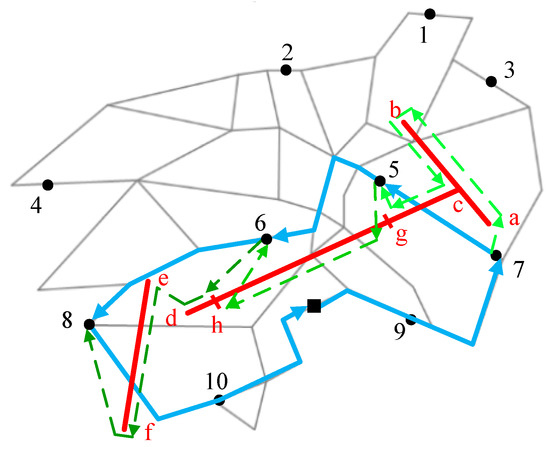
Figure 7.
An illustration of the giant drone route for the example case.
4.3. Local Search Improvement
In this section, local search is introduced to improve the feasible solution given by the constructive heuristics (CFRS or RFSS). The framework of local search is displayed in the pseudo-code of Algorithm 6.
Given a feasible solution obtained by CFRS or RFSS as an initial solution, s, (Line 1), the neighborhood list would be first initialized (Line 4). Then, the neighborhood list would be explored exhaustively every time, which returns the best improvement s’ (Line 4). The current solution s would be replaced with s’ if s’ is better (Line 6), which would reinitialize the neighborhood list (Line 7) and restart the counter k (Line 8). If all the neighborhoods in the list has been run without improvement for a determined number of times, the local search would be ended. The neighborhoods used in this part are detailed in Section 4.3.1, Section 4.3.2 and Section 4.3.3.
| Algorithm 6: Local Search | |
| 1 | s: the initial solution given by the constructive heuristic |
| 2 | k = 1 |
| 3 | WHILEk ≤ N DO |
| 4 | Find the best neighbor s’ ∈ N(s) |
| 5 | IF s’ < s THEN |
| 6 | s ← s’ |
| 7 | Reinitialize N |
| 8 | k = 1 |
| 9 | ELSE |
| 10 | k = k + 1 |
| 11 | END IF |
| 12 | END WHILE |
Combined with the local search, the two heuristics CFRS and RFSS can generate two hybrid algorithms, denoted as CFRS-LS and RFSS-LS respectively.
4.3.1. Neighborhood 1: Exchanging Sub-Solutions
This neighborhood is set to exchange two sub-solutions, such as sub-solutions {2, a, b, 3} and {6, c, d, 7} in Figure 8. Since the operation has nothing to do with the drone flights inside the sub-solutions, only the length of the vehicle route would be changed, which is always feasible with incapacitated endurance of the vehicle. Specifically, the visiting direction of the sub-solutions can be changed, which causes four conditions due to the different vehicle routes. Only one condition is displayed in Figure 8 as the vehicle route is {1-6-7-4…5-2-3-8} while the route can also be changed as {1-7-6-4…5-2-3-8, 1-6-7-4…5-3-2-8}, and {1-7-6-4…5-3-2-8}, among which the best way of exchanging would be selected to decrease the task completing time the most.
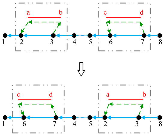
Figure 8.
An illustration of exchanging sub-solutions.
4.3.2. Neighborhood 2: Exchanging Powerline Segments
This neighborhood relocates two powerline segments in two flight paths. In Figure 9, the powerline segments <c,d> and <e,f> are exchanged to check whether the task completing time can be decreased. Specifically, there are four exchange ways with different inspection directions of the two wire segments. Figure 9 illustrates an example of the operation for Neighborhood 2, where segments <c,d> and <e,f> are exchanged, and two new sub-solutions, {1, a, b, e, f, 2} and {3, c, d, 4}, are generated. In each operation, the feasibility would be verified through checking the drone’s endurance and the cooperation with the ground vehicle. Only when all constraints are satisfied, the objective value of the new solution can be calculated.
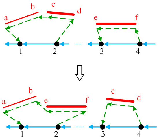
Figure 9.
An illustration of exchanging powerline segments.
4.3.3. Neighborhood 3: Splitting Powerline Segments
This neighborhood split a powerline segment into two new segments through the bisection method. Then, it would be attempted to insert the new ones into two other sub-solutions under the constraints for the drone and the vehicle, which can improve the utilization of the drone’s endurance. Correspondingly, the vehicle node for launching or recycling the drone is adjusted according to the node where the drone enters or leaves the powerline network. For instance, the segment <c,d> is split into segments <c,g> and <g,d> in Figure 10, which are inserted into the original sub-solutions {1, a, b, 2} and {5, e, f, 6}, respectively. After adjusting the vehicle node, the new sub-solutions are presented as {1, a, b, c, g, 3} and {3, g, d, e, f, 6}.
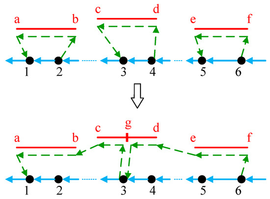
Figure 10.
An illustration of splitting powerline segments.
5. Case Study and Results
In this section, a case based on the road network and the powerline network in Ji’an, a city in China, is presented. Computational experiments were conducted to compare the proposed algorithms and obtain managerial insight.
5.1. Case Description
The power grid network includes three size of high-voltage powerlines (550 KV, 220 KV and 110 KV) in Ji’an, as shown in Figure 11a. Since the sensors on the drone scans one area at a time, meaning several lines that are very close to each other can be inspected at the same time, the actual power grid is described as a network with multiple arcs.
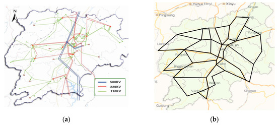
Figure 11.
The powerline network and the road network in Ji’an: (a) the power grid in Ji’an; and (b) the road network in Ji’an.
The road network was built based on the main roads of Ji’an from the online map. There are 40 crossings in the road network, and the actual roads among the crossings are marked with black lines in Figure 11b. Specifically, the latitude and longitude coordinates of the crossings were obtained from the Baidu map. A tool provided by Baidu was applied for the distance calculation of the actual roads, generating the initial distance matrix. Then, the crossing distance matrix was filled by the Floyd algorithm to acquire the shortest distance between any two crossings based on the road network.
Three instances with different scales of powerline networks were designed in the experiment. Six arcs of the 550 KV powerlines were combined with the road network, which formed the small-scale case. Similarly, 220 KV powerlines and 110 KV powerlines were used for the medium-scale case and the large-scale case, respectively. The details for three transmission lines is displayed in Table 1.

Table 1.
Detail settings for the three instances.
The parameters related with the vehicle and drone were set according to typical ones in practical application, as shown in Table 2.
Table 2.
The Parameters of vehicle and Drone.
5.2. Experiment Results and Analysis
5.2.1. Experiment Results
To compare the performance of the proposed algorithms, two constructive heuristics CFRS and RFSS, as well as two hybrid algorithms CFRS-LS and RFSS-LS, were all applied to solve the above three instances. In addition, the impact of the local search was also demonstrated through the comparison between the results given by CFRS and CFRS-LS, or RFSS and RFSS-LS.
Table 3 presents the computational results for the three instances. For the small-scale and medium-scale instances, the results given by CFRS were better than those by RFSS. For the large-scale instance, RFSS performed better than CFRS. There was no significant difference on the computational time of the two constructive heuristics. In addition, the local search could efficiently improve the initial solutions obtained by constructive heuristics. Taking the large-scale instance as an example, after the operations of local search, the objective value decreased from 63.06 to 56.11 for CFRS and from 62.04 to 55.06 for RFSS, respectively, achieving 11.02% and 11.25% reductions in the completing time. The computational time for small-scale and medium-scale instances was controlled in 2 s while the process solving the large-scale instance consumed about 5 s.
Table 3.
Results of the three instances by different algorithms.
5.2.2. Sensitivity Analysis
Two critical parameters related to the performance of the drone were considered in the sensitivity analysis: the inspection speed and the capacity of battery power. The flying speed of the drone during its inspection of the powerline was mainly constrained by the performance of the inspection sensor carried by the drone and the ability of the software system for inspection data analysis. Technical improvement on these hardware and software could improve the inspection speed of the drone. The capacity of the battery power constrains the endurance of the drone in each flying route. Thus, both parameters are critical in the investigated problem, and sensitivity analysis on these parameters could help us observe their impact on the efficiency of the whole cooperated inspection system. The medium-scale instance was used in the sensitivity analysis, and the best objective values of four algorithms are reported in Table 4.
Table 4.
Sensitivity results for different inspection speeds and battery powers.
(1) Impact analysis of the inspection speed
For analyzing the impact of the inspection speed, we varied its value from 5 to 40 km/h, and calculated the coverall completing time under different inspection speeds. From the computational results in Table 4, the overall completing time decreased as the inspection speed increased. To further analyze the effect of this parameter, the detail experiment results with the battery power of 5000 mAh and different inspection speeds from 5 to 40 km/h are reported in Figure 12.
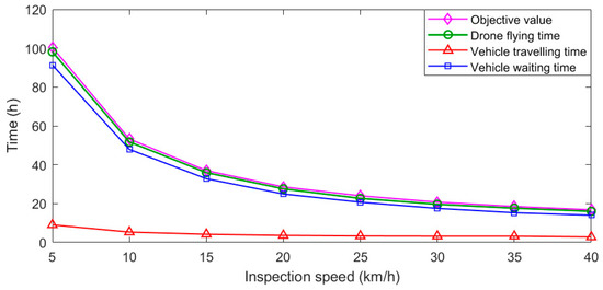
Figure 12.
Computational results under different inspection speeds.
As the inspection speed increased from 5 to 20 km/h, the overall completing time showed a significant reduction from 100.41 h to 28.59 h. When the inspection speed was over 20 km/h, the completing time decreased slowly as the inspection speed increased. The flight time of the drone, the travelling time and waiting time of the vehicle are also presented. The varying of the flight time of the drone and the waiting time of the vehicle was similar to that of the overall completing time. The absolute reduction of the vehicle’s travelling time was not significant, from 9.06 h to 2.28 h, but its relative reduction was great. Overall, the improvement of inspection speed could effectively reduce the overall completing time.
(2) Impact analysis of the battery capacity
To investigate the effects of the drone’s battery capacity, the detailed results for the battery power varying from 2000 to 8000 mAh was analyzed, while the inspection speed was fixed at 25 km/h. The results are reported in Figure 13.
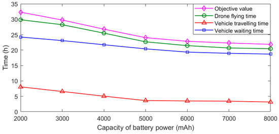
Figure 13.
Computational results under different battery powers.
As shown in Figure 13, the objective value, i.e. the overall completing time, decreased with the increasing of the battery capacity. Similar trends were also observed for the drone’s flying time, the vehicle’s travelling time and waiting time. Because higher battery capacity enabled the drone to fly a longer distance in each sub-solution route, the vehicle stopped fewer times for launching and recycling of the drone, which caused a higher utilization of the drone endurance on powerline inspection. The flatter curve in Figure 13 indicates that improving the efficiency by increasing the drone’s battery capacity was possible, but its influence was lower compared to that of the inspection speed, as shown in Figure 12.
6. Conclusions
In this paper, recognizing that the cooperation of the ground vehicle and the drone can significantly improve the efficiency of high-voltage powerline inspection, a novel powerline inspection system is considered. When the vehicle travels on the road network while the drone flies along the high-voltage power transmission line, a new variant of routing problem is generated for simultaneously optimizing the routes for the vehicle and the drone, which integrates the classical Travelling Salesman Problem and Arc Routing problem. To solve the problem, two constructive heuristics based on CFRS and RFSS are designed. In addition, the local search with three neighborhood operators is proposed to improve the quality of the solution obtained by CFRS and RFSS.
Different-scale cases based on the road network and the high-voltage powerline network of Ji’an were designed to test the performance of the proposed algorithms. Furthermore, two factors were considered in sensitivity tests: the drone’s inspection speed and battery capacity. Experimental results indicate that proper improvement on technologies for improving the inspection speed or enlarging the capacities of the drone endurance were helpful to shorten the overall completing time of the powerline inspection. In addition, technical improvement on the inspection speed was more important than that on the battery capacity.
In the investigated system, it is assumed that the vehicle can only carry one drone. A meaningful future research is to study the system involving multiple drones, which would be more important for large scale networks. New algorithms also have to be developed for optimizing the routes for multiple drones and their vehicle.
Author Contributions
Conceptualization, J.S.; Methodology, J.S. and Z.L.; Validation, Y.L., J.S. and J.H.; Formal Analysis, Y.L.; Investigation, T.Z.; Data Curation, Y.L. and T.Z.; Writing-Original Draft Preparation, Y.L.; Writing-Review & Editing, J.S.; Supervision, J.S.; Project Administration, Z.L.; Funding Acquisition, J.H.
Funding
The research was funded by the National Natural Science Foundation of China (grant Nos. 71771215 and 71471175) and the Natural Science Fund for Distinguished Young Scholars of Hunan Province (2018JJ1035).
Conflicts of Interest
The authors declare no conflict of interest. The founding sponsors had no role in the design of the study; in the collection, analyses, or interpretation of data; in the writing of the manuscript, and in the decision to publish the results.
References
- West, L.M.; Segerstrom, T. Commercial applications in aerial thermography: Power line inspection, research, and environmental studies. Thermosense XXII 2000, 4020, 382–387. [Google Scholar]
- Jiang, S.; Jiang, W.; Huang, W.; Yang, L. UAV-based oblique photogrammetry for outdoor data acquisition and offsite visual inspection of transmission line. Remote Sens. 2017, 9, 278. [Google Scholar] [CrossRef]
- Ameren Successfully Completes Industry-Leading 60-Mile Drone Flight over Transmission Lines, Paving the Way for Safe, Efficient Aerial Infrastructure Inspections. Available online: https://www.bv.com/news/ameren-successfully-completes-industry-leading-60-mile-drone-flight-over-transmission-lines (accessed on 3 December 2018).
- I&M Using Drones to Inspect Randolph County Transmission Lines. Available online: http://www.winchesternewsgazette.com/news/i-m-using-drones-to-inspect-randolph-county-transmission-lines/article_5bb1a12a-0f5a-11e9-a35b-a3447dbf4024.html (accessed on 3 January 2019).
- Deng, C.; Wang, S.; Huang, Z.; Tan, Z.; Liu, J. Unmanned aerial vehicles for power line inspection: A cooperative way in platforms and communications. J. Commun. 2014, 9, 687–692. [Google Scholar] [CrossRef]
- Wu, F.F.; Zheng, F.L.; Wen, F.S. Transmission investment and expansion planning in a restructured electricity market. Energy 2006, 31, 954–966. [Google Scholar] [CrossRef]
- Niemi, R.; Lund, P.D. Decentralized electricity system sizing and placement in distribution networks. Appl. Energy 2010, 87, 1865–1869. [Google Scholar] [CrossRef]
- Fürsch, M.; Hagspiel, S.; Jägemann, C.; Nagl, S.; Lindenberger, D.; Tröster, E. The role of grid extensions in a cost-efficient transformation of the European electricity system until 2050. Appl. Energy 2013, 104, 642–652. [Google Scholar] [CrossRef]
- Guerra, O.J.; Tejada, D.A.; Reklaitis, G.V. An optimization framework for the integrated planning of generation and transmission expansion in interconnected power systems. Appl. Energy 2016, 170, 1–21. [Google Scholar] [CrossRef]
- Sarıca, K.; Kumbaroğlu, G.; Or, I. Modeling and analysis of a decentralized electricity market: An integrated simulation/optimization approach. Energy 2012, 44, 830–852. [Google Scholar] [CrossRef]
- Sawada, J.; Kusumoto, K.; Maikawa, Y.; Munakata, T.; Ishikawa, Y. A mobile robot for inspection of power transmission lines. IEEE Trans. Power Deliv. 1991, 6, 309–315. [Google Scholar] [CrossRef]
- Toussaint, K.; Pouliot, N.; Montambault, S. Transmission line maintenance robots capable of crossing obstacles: State-of-the-art review and challenges ahead. J. Field Robot. 2009, 26, 477–499. [Google Scholar] [CrossRef]
- Katrasnik, J.; Pernus, F.; Likar, B. A survey of mobile robots for distribution power line inspection. IEEE Trans. Power Deliv. 2010, 25, 485–493. [Google Scholar] [CrossRef]
- Gonçalves, R.S.; Carvalho, J.C.M. Review and latest trends in mobile robots used on power transmission lines. Int. J. Adv. Robot. Syst. 2013, 10, 408. [Google Scholar] [CrossRef]
- Guo, J.; Wu, G.; Liu, B.; Wang, Q.; Wang, Z.; Ma, Y.; Li, S.; Xu, Q.; Liu, B. Database environment of an inspection robot for power transmission lines. In Proceedings of the 2009 Asia-Pacific Power and Energy Engineering Conference, Wuhan, China, 27–31 March 2009; pp. 1–4. [Google Scholar]
- Whitworth, C.C.; Duller, A.W.G.; Jones, D.I.; Earp, G.K. Aerial video inspection of overhead power lines. Power Eng. J. 2001, 15, 25–32. [Google Scholar] [CrossRef]
- Fan, F.; Wu, G.; Wang, M.; Cao, Q.; Yang, S. Multi-Robot Cyber Physical System for Sensing Environmental Variables of Transmission Line. Sensors 2018, 18, 3146. [Google Scholar] [CrossRef]
- Liu, Y.; Liu, Z.; Shi, J.; Wu, G.; Chen, C. Optimization of Base Location and Patrol Routes for Unmanned Aerial Vehicles in Border Intelligence, Surveillance, and Reconnaissance. J. Adv. Transp. 2019, 2019, 9063232. [Google Scholar] [CrossRef]
- Besada, J.A.; Bergesio, L.; Campaña, I.; Vaquero-Melchor, D.; López-Araquistain, J.; Bernardos, A.M.; Casar, J.R. Drone Mission Definition and Implementation for Automated Infrastructure Inspection Using Airborne Sensors. Sensors 2018, 18, 1170. [Google Scholar] [CrossRef]
- Seo, J.; Duque, L.; Wacker, J. Drone-enabled bridge inspection methodology and application. Autom. Constr. 2018, 94, 112–126. [Google Scholar] [CrossRef]
- Moore, A.J.; Schubert, M.; Rymer, N. Autonomous Inspection of Electrical Transmission Structures with Airborne UV Sensors, NASA Report on Dominion Virginia Power Flights of November 2016. 2017. Available online: https://ntrs.nasa.gov/archive/nasa/casi.ntrs.nasa.gov/20170004692.pdf (accessed on 10 May 2017).
- Máthé, K.; Buşoniu, L. Vision and control for UAVs: A survey of general methods and of inexpensive platforms for infrastructure inspection. Sensors 2015, 15, 14887–14916. [Google Scholar] [CrossRef]
- Hrabar, S.; Merz, T.; Frousheger, D. Development of an autonomous helicopter for aerial powerline inspections. In Proceedings of the 2010 1st International Conference on IEEE Applied Robotics for the Power Industry (CARPI), Montreal, QC, Canada, 5–7 October 2010; pp. 1–6. [Google Scholar]
- Huang, S.; Gu, X.; Zhang, J. Design of new oil moving fixed-wing unmanned aerial vehicle for power line patrolling. Autom. Electr. Power Syst. 2014, 38, 104–108. [Google Scholar]
- Xie, X.; Liu, Z.; Xu, C.; Zhang, Y. A Multiple Sensors Platform Method for Power Line Inspection Based on a Large Unmanned Helicopter. Sensors 2017, 17, 1222. [Google Scholar] [CrossRef]
- Martinez, C.; Sampedro, C.; Chauhan, A.; Campoy, P. Towards autonomous detection and tracking of electric towers for aerial power line inspection. In Proceedings of the 2014 International Conference on IEEE Unmanned Aircraft Systems (ICUAS), Orlando, FL, USA, 27–30 May 2014; pp. 284–295. [Google Scholar]
- Li, B.; Chen, C. Transmission line detection based on a hierarchical and contextual model for aerial images. J. Electron. Imaging 2018, 27, 043054. [Google Scholar] [CrossRef]
- Bhola, R.; Krishna, N.H.; Ramesh, K.N.; Senthilnath, J.; Anand, G. Detection of the power lines in UAV remote sensed images using spectral-spatial methods. J. Environ. Manag. 2018, 206, 1233–1242. [Google Scholar] [CrossRef]
- Li, Z.; Liu, Y.; Walker, R.; Hayward, R.; Zhang, J. Towards automatic power line detection for a UAV surveillance system using pulse coupled neural filter and an improved Hough transform. Mach. Vis. Appl. 2010, 21, 677–686. [Google Scholar] [CrossRef]
- Nguyen, V.N.; Jenssen, R.; Roverso, D. Automatic autonomous vision-based power line inspection: A review of current status and the potential role of deep learning. Int. J. Electr. Power Energy Syst. 2018, 99, 107–120. [Google Scholar] [CrossRef]
- La Cour-Harbo, A. Quantifying risk of ground impact fatalities for small unmanned aircraft. J. Intell. Robot. Syst. 2019, 93, 367–384. [Google Scholar] [CrossRef]
- Liu, C.A.; Wang, L.; Liu, C. Mission planning of the flying robot for powerline inspection. Prog. Nat. Sci. 2009, 19, 1357–1363. [Google Scholar] [CrossRef]
- Baik, H.; Valenzuela, J. Unmanned Aircraft System Path Planning for Visually Inspecting Electric Transmission Towers. J. Intell. Robot. Syst. 2018, 1–15. [Google Scholar] [CrossRef]
- Luo, Z.; Liu, Z.; Shi, J. A two-echelon cooperated routing problem for a ground vehicle and its carried unmanned aerial vehicle. Sensors 2017, 17, 1144. [Google Scholar] [CrossRef]
- D’Andrea, R. Guest editorial can drones deliver? IEEE Trans. Autom. Sci. Eng. 2014, 11, 647–648. [Google Scholar] [CrossRef]
- Clarke, G.; Wright, J.W. Scheduling of vehicles from a central depot to a number of delivery points. Oper. Res. 1964, 12, 568–581. [Google Scholar] [CrossRef]
© 2019 by the authors. Licensee MDPI, Basel, Switzerland. This article is an open access article distributed under the terms and conditions of the Creative Commons Attribution (CC BY) license (http://creativecommons.org/licenses/by/4.0/).