1. Introduction
In all highly developed societies, energy conversion processes need to be carried out with the highest possible energy efficiency together with a reduction in energy consumption but also with great concern for the environment. This approach is nowadays known as so-called “good industrial practice”, and it is utilised in all branches of industry. It is supported and, in many situations, even enforced by the European Commission Regulations. As a typical example, the issue of high energy efficiency of all refrigeration cycles is combined with the reduction of greenhouse gas emissions. Succeeding regulations regarding environmental protection, for instance, as reported in Kigali Amended [
1], are very strict regarding the use of synthetic coolants, which are harmful for the environment. One of the solutions is to use natural refrigerants due to their negligible environmental impact and high market availability [
2]. This has led many researchers to examine the refrigeration cycles with natural cooling media, e.g., carbon dioxide (denoted as R744), which is featured with a Global Warming Potential (GWP) equal to 1 and an Ozone Depletion Potential (ODP) equal to 0; it is also non-flammable and non-toxic refrigerant.
The first research on R744 as a working fluid in refrigeration cycle, which was conducted by Lorentzen [
3], showed great potential for application, although the author pointed out a reduction in cooling capacity at elevated temperatures as a result of the low critical temperature of 31.1 °C and high critical pressure of 73.8 bar. According to Goodarzi et al. [
4], the simple vapour compression R744 cycle results in a much smaller coefficient of performance (COP) in comparison to the synthetic equivalents working at similar temperature variations. This effect is connected to high thermodynamic losses during the expansion process due to the transcritical nature of the R744 vapour compression cycle. Therefore, a modification of the R744 system configuration to improve the system’s energy performance, especially during transcritical operation, is needed [
5]. Moreover, well-designed components installed in the R744 vapour compression cycle influence the COP improvement [
6].
COP improvement was attained through implementation of the liquid separator and flash gas bypass valve to the R744 refrigeration system. The R744 booster system is commonly installed in cold and moderate climate zones, especially in the Scandinavian region [
7]. Further energy performance improvement can be achieved through application of the parallel compressor, which sucks fluid directly from the liquid separator [
8]. This system reduces the electric power consumption by size reduction of the medium temperature (MT) compressor during utilisation in the summer season in hot climates [
6]. Sharma et al. [
9] stated that the R744 parallel compression system obtains higher COP when compared to the conventional R410A direct expansion system in the northern and central parts of the United States of America. The COP improvement of the R744 parallel compression system was also observed for a heat pump application [
10]. Gullo et al. [
11] stated that the R744 “all-in-one” transcritical system with mechanical subcooling can reduce the system inefficiencies by up to 59%. However, the high thermodynamic losses during expansion process in the high-pressure expansion valve limit the possible COP improvement. Hence, one of the solutions is to use the ejector technology as the main expansion device and to recover potential expansion work [
12].
Gullo and Cortella [
13] concluded that the use of a system with a two-phase ejector as the main expansion device is the most efficient choice for upgrading the system’s performance. Catalán-Gil et al. [
14] confirmed COP improvement of the R744 transcritical system equipped with the gas ejector up to 29.5% when compared to the standard booster system. The main objective of the ejector application is to recover the pressure-related work of the supersonic motive flow and convert it to kinetic energy in order to exchange the momentum with the entrained low pressure suction stream. The consequence is that the pressure at the outlet is higher than the pressure of the suction stream, which results in higher pressure at the compressor inlet and thus less compression work is required as compared with the standard booster type cycle. Complex phenomena appear in the R744 two-phase ejector such as supersonic flow in the converging-diverging nozzle, momentum transfer in the mixing section, and pressure increment of the mixed flow in the diffuser, necessitating the evaluation of the ejector performance using a more advanced mathematical approach [
15].
Kornhauser [
16] was the first to present a 1D model for a synthetic medium system with the ejector to recover the expansion work. He showed a COP improvement of 21% over the conventional cycle with the expansion valve for different refrigerants. Li and Groll [
17] performed a numerical investigation of the R744 ejector-based system and obtained a significant COP improvement compared to the standard direct expansion system or R744 booster system with the flash gas bypass (FGB) concept. The authors stated that the COP improvement was more than 16% when compared to the basic transcritical R744 cycle for air-conditioning operating conditions. A 0D model was also implemented for the dynamic simulation of the R744 ejector-based refrigeration system by Richter [
18]. However, that model assumes the efficiency of the ejector given by Elbel and Hrnjak [
12], resulting in low accuracy at the wide ranges found in supermarket applications.
Sumeru et al. [
19] showed in their paper that the COP improvement of R744 transcritical ejector based system was up to 55% for thermodynamic analyses and up to 20% for experimental investigations. In an experimental study, Elbel and Hrnjak [
12] obtained a cooling capacity and COP improvement of up to 8% and 7%, respectively. This discrepancy between theoretical and experimental COP improvements is caused by the idealisation of the refrigeration components, especially the two-phase ejector. Moreover, the ejector models used for such computations do not take the complex ejector geometry and local flow phenomena inside the device into consideration. This suggests a need for conducting more advanced numerical analyses, such as computational fluid dynamics (CFD) models, to allow for the evaluation of the flow behaviour inside the ejector.
The commonly used approach in the numerical investigation is the homogeneous equilibrium model (HEM), assuming mechanical and thermodynamic equilibrium between both phases inside the ejector [
20]. This methodology is mostly derived from the concepts of Kornhauser [
16]. Smolka et al. [
21] used the homogeneous real fluid approach and applied an energy equation expressed in terms of the specific enthalpy instead of the standard temperature basis. The equation was employed in the Ansys Fluent solver utilising the user defined functions (UDF). In this case, the error margin of CFD results validated against real test data was kept below the level of 10% for most of the operating points above the critical point. Similar work was done by the previously mentioned study by Lucas et al. [
20], but the authors used an OpenFOAM solver instead of commercial Ansys Fluent. Unfortunately, the HEM featured increasing inaccuracy with a decreasing motive nozzle temperature and a decreasing distance to the saturation line.
To extend a regime in which high quality results are obtained, another approach called the homogeneous relaxation model (HRM) was introduced. The idea was proposed by Bilicki et al. [
22], followed later by comparison of the HEM, HRM results and experimental data provided by Downar-Zapolski et al. [
23]. The aforementioned model evaluates the metastable effect during the expansion process by an additional vapour mass balance governing equation and the semi-empiric relaxation time (RT) definition [
22]. Angielczyk et al. [
24] investigated the HRM for the CO
supersonic two-phase flow through the ejector motive nozzle and presented a novel correlation for RT by entering additional information, such as temperature and quality profiles as well as the critical mass flow rates (MFR). Colarossi et al. [
25] applied the HRM for R744 condensing two-phase ejector simulations for improvement in relation to the HEM in terms of accuracy and a wider operation regime of high quality results. Palacz et al. [
26] validated the HRM CFD model of the R744 two-phase ejector with RT defined in [
24]. The authors indicated that both nozzles had a mass flow rates accuracy improvement of 5% compared with the HEM. Haida et al. [
27] modified the HRM by searching for RT coefficients based on the genetic algorithm optimisation procedure. The authors stated that the modified HRM extended the application range of the CFD model in the subcritical region to motive nozzle pressures above 59 bar.
However, the very time-consuming nature of CFD simulations for single operating points makes these models unfavourable for implementation into system analysis. Under these circumstances, many researchers use the 0D or 1D mathematical model of the two-phase ejector. The implementation of 0D/1D ejector models to system simulations allows system performance evaluation due to several assumptions of the simplified ejector model. Therefore, the dynamic simulations of the R744 ejector-based refrigeration system were performed either based on the assumptions of the two-phase ejector, such as fixed ejector efficiency [
28] or accepting constant efficiencies of ejector parts for selected operating regimes [
29]. The aforementioned assumptions may cause high discrepancy in theoretical predictions of the motive and suction mass flow rates when compared with the results of experimental tests and more advanced CFD approaches.
As already mentioned, the CFD numerical approach and experimental data enable more accurate evaluation of ejector performance than 0D or 1D models. However, those solutions are not suitable, particularly for dynamic calculations, because of their high computational cost. Hence, there is still a need to develop more versatile computational tools for steady-state and dynamic system analysis of ejector units. One solution is the implementation of a low-order fast and accurate model based on CFD results combined with the experimental data of the system analysis. One of these approaches is the reduced-order model (ROM), proposed by Haida et al. [
30], which was developed based on the proper orthogonal decomposition (POD) approximation together with the radial basis interpolation functions (RBF) [
31]. Haida et al. [
30] showed that the POD-RBF results in mass flow rates with
accuracy compared to the experimental data. It was developed on the basis of a 2D axisymmetric CFD model proposed by Smolka et al. [
21], which implements an ejector in the R744 transcritical cycle to give a wide range of operating conditions and a cooling capacity. The single case computational time of ROM was shown to be below 0.05 s, which allows its utilisation in dynamic simulations. The low-order model of the R744 two-phase ejector was also enhanced by hybrid combination of the CFD results together with the experimental data by Haida et al. [
32]. The hybrid ROM maintained high accuracy and fast simulations at a very wide operational envelope for the R744 Heat, Ventilation, Air-Conditioning and Refrigeration (HVAC&R)supermarket system. The discussed model was used to generate maps of ejectors performance installed in the multi-ejector module [
33] for the R744 supermarket system. Therefore, the implementation of ROM in the system analyses of the R744 ejector-based refrigeration cycles, being a novel approach for non-commercial applications, can be very valuable in terms of the accuracy of computational results in comparison to commonly used methodology, without any negative effect on the computational time.
The main aim of this study was to integrate the two-phase ejector hybrid ROM with the R744 refrigeration system based on object-oriented modelling to produce a dynamic system simulation. First, the three mathematical models of the R744 two-phase ejector, i.e., 0D model, 1D model and the hybrid ROM model, are briefly discussed and confront. Then, the accuracy of all these three ejector models was evaluated by comparing selected numerical results with the experimental measurements. In the next section, these three models are applied into system analysis of the refrigeration cycle to determine its COP. Finally, dynamic simulation of the hybrid ROM ejector model integrated with the R744 refrigeration system was presented based on the summer campaign in three different climate zones. In all system analyses carried out in this work, the OpenModelica (OM) software was utilised.
3. Object-Oriented Modelling of the R744 Transcritical System
The object-oriented model of the R744 transcritical system equipped with the two-phase ejector allows dynamic simulation for performance evaluation and control strategy definition. Moreover, the integration of different ejector models with the R744 cycle allows the sensitivity of the ejector model to be observed with respect to modifications of dynamic system parameters. Hence, the validation procedure of the object-oriented ejector models gives information about the accuracy of each investigated model to select the proper model for system implementation.
The software used for this work was OM, which is the open source environment based on the Modelica 3.3 language for simulating, optimising and analysing complex systems for industrial and academic usage [
35]. Moreover, it allows the performance of steady-state as well as dynamic simulations of constructed systems and the analysis of the system as a whole using the transfer behaviour between components as opposed to other well-known equation solvers used for thermodynamic applications. This approach is called object-oriented modelling which is a construction of complex systems based on single objects with well-defined properties or transfer behaviour as a set of interacting and inter-related objects. This kind of modelling allows the visualisation and analysis of complex systems; they can also be modified and their construction can be changed in an easy way. Object-oriented designs are also more maintainable. The CoolProp package [
36] containing thermophysical properties of R744 was used to evaluate the flow behaviour inside each system component.
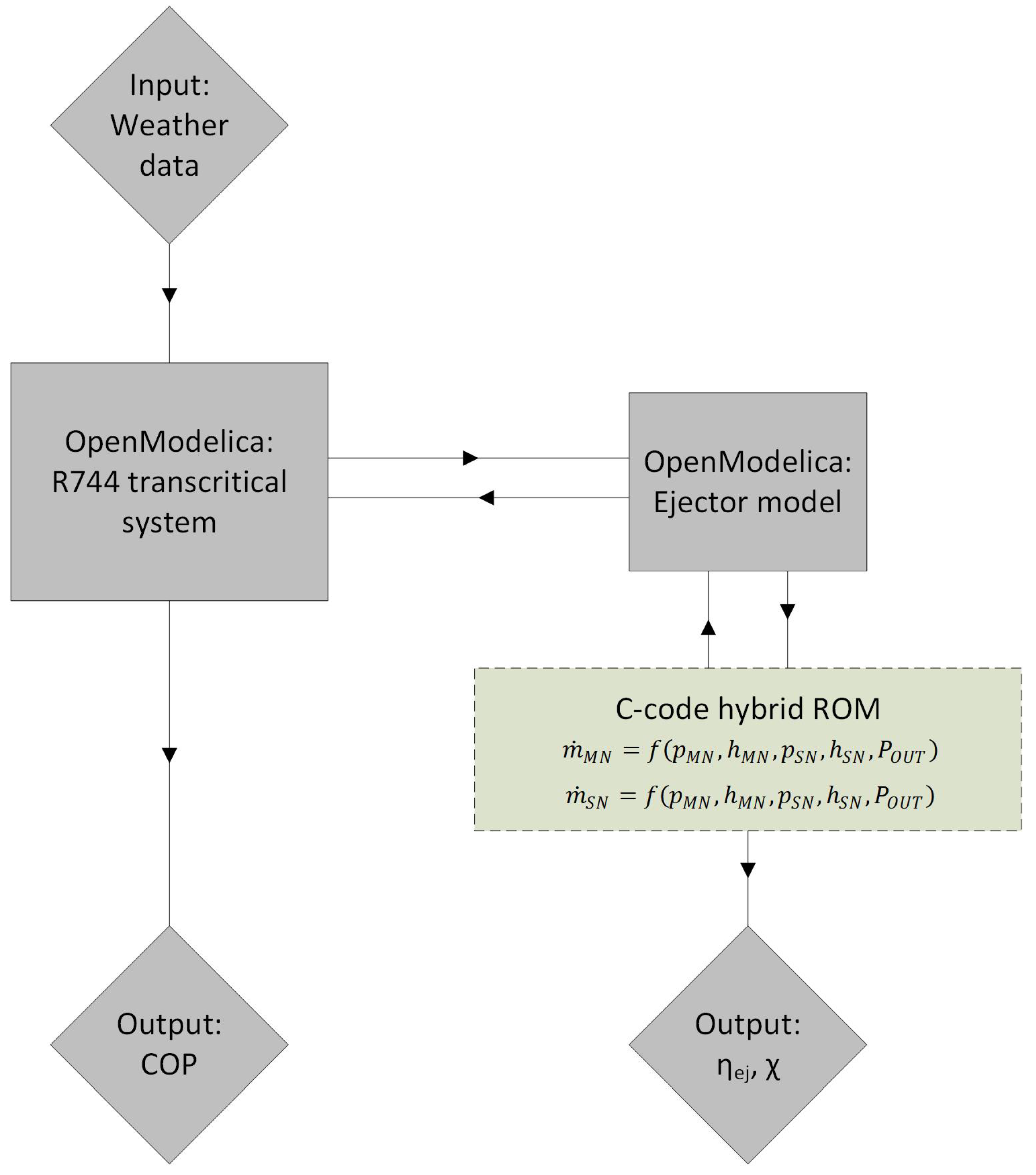
The 0D model and 1D model of the R744 two-phase ejector were directly implemented to the Modelica software due to the simplicity of both approaches. However, the more complex hybrid ROM was compiled using C-code external functions. Each external function was defined to calculate either the motive nozzle or suction nozzle mass flow rate given from the hybrid ROM under specified operating conditions.
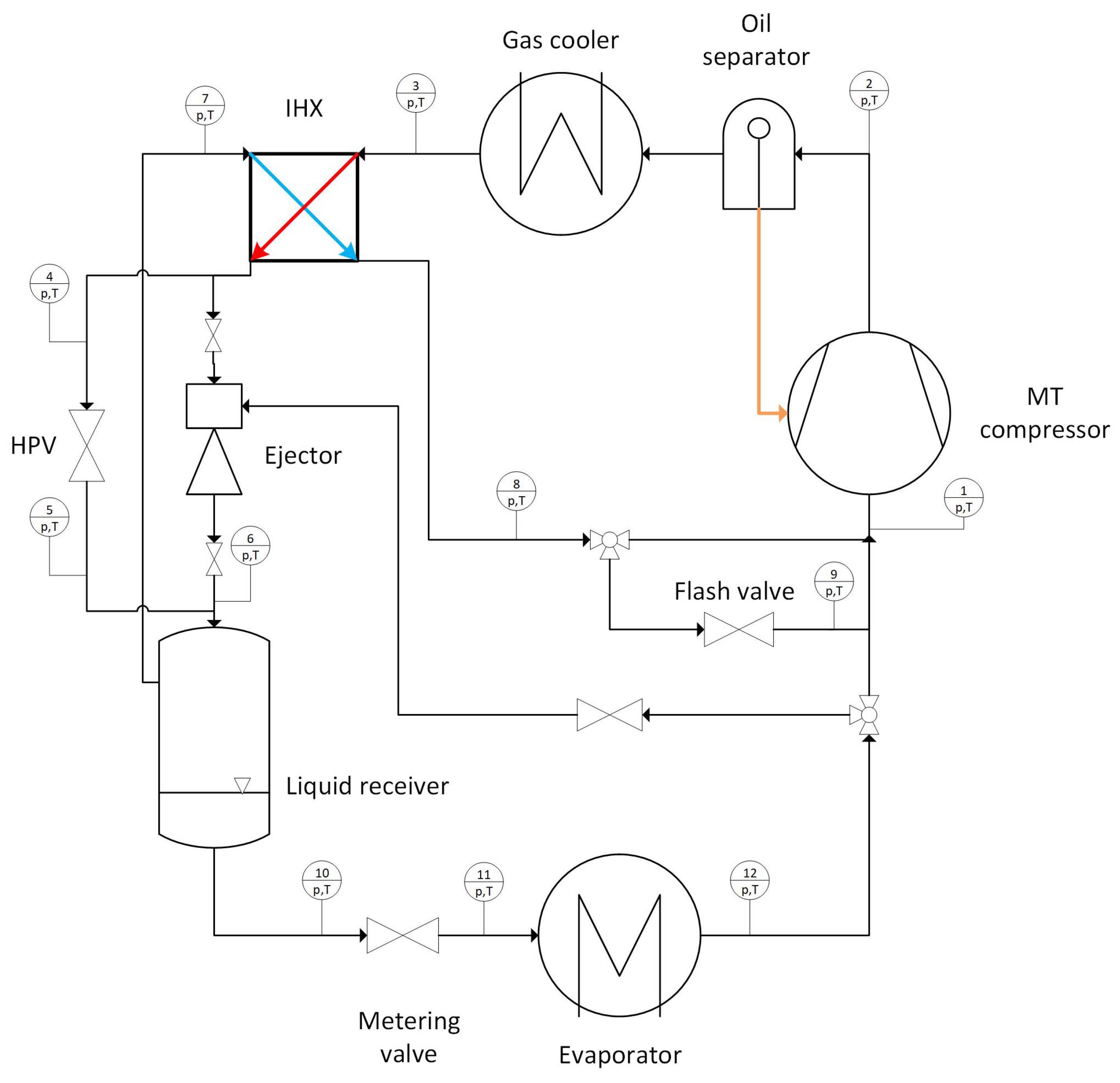
The mathematical approaches of the two-phase ejector were integrated to the R744 transcritical refrigeration system to investigate the system model derivation and ejector work during annual operation. The layout of the R744 ejector-based transcritical system is shown in
Figure 3. The R744 loop was designed as a booster type system. The superheated vapour R744 stream from the evaporator outlet is compressed in the semi-hermetic compressor to the discharge pressure level. The high-side pressure is set according to the ambient conditions, either under subcritical or transcritical conditions. The discharged flow outside the compressor rejects the heat in the gas cooler heat exchanger due to the heat transfer between the refrigerant and auxiliary flow, i.e., the glycol–water mixture. Then, the internal heat exchanger (IHX) allows heat transfer between the high-side pressure and intermediate pressure to increase the sub-cooling degree under subcritical conditions and decrease the outlet temperature under transcritical conditions. The sub-cooled flow is expanded either by the high pressure electronic expansion valve (HPV) or by the two-phase ejector. Moreover, the ejector entrains the vapour flow from the evaporator outlet and the mixed flow enters the liquid receiver together with the throttled flow from the HPV. In the liquid receiver, the liquid saturated phase discharges the evaporator, and the vapour phase of R744 flows through IHX to absorb heat from the high-side pressure stream. The vapour outflowing from the IHX is expanded by the flash gas bypass and enters the compression suction side. The R744 liquid outflowing from the liquid receiver is expanded by the metering valve to the MT pressure and absorbs the heat in the evaporator. Finally, the R744 stream outflowing from the evaporator experiences superheat conditions, which prevents any liquid droplets forming in the compressor.
The system performance analysis was done based on the first-law analysis. Therefore, COP was defined as the ratio of the heat absorbed in the evaporator to the internal work rate of the compressor:
where COP is the coefficient of performance,
is the heat rate absorbed in the evaporator in W and
is the internal work rate of the compressor in W. The heat rate and the internal work rate are defined as follows:
where
SH is the superheat degree in K and the indexes are defined according to
Figure 3. The specific enthalpy at the compressor outlet was defined based on the isentropic efficiency in the following form:
The rate of heat in the gas cooler was calculated as follows:
The outlet conditions are defined either by the set of sub-cooling degrees or by a set of the temperatures and pressures under transcritical conditions. The energy balance equation was defined for IHX in the following form:
All valves presented in
Figure 3 were defined to control the expansion process and discharge the evaporator as follows:
where OD is the opening degree of the valve and
is the valve flow coefficient in m
s
. The liquid receiver was evaluated based on the mass balance and energy balance equation:
where
V is the volume of the liquid receiver in m
,
determines the mass accumulation in the liquid receiver in kg·s
and
is the energy accumulation in W. Finally, the ejector work was calculated using the ejector efficiency defined in Equation (
2). Moreover, the ejector performance was also evaluated based on the pressure ratio
between the outlet and the suction nozzle:
Figure 4 presents the flowchart of the computation procedure of the R744 transcritical system at a single time step. The global input data is a weather data to evaluate system work at different test campaigns, i.e., daily or annual. The object-oriented system solved the governing equations for all considered components. The object-oriented ejector model is combined with the C-code hybrid ROM using external functions. Hence, the motive nozzle and the suction nozzle mass flow rates were reached by calling the hybrid ROM at defined input parameters. Based on the input parameters and results given by the hybrid ROM, the ejector model computed continuously the ejector efficiency and the mass entrainment ratio. Finally, the COP value of the investigated system was calculated.
4. Comparison of the Investigated R744 Two-Phase Ejector Numerical Models
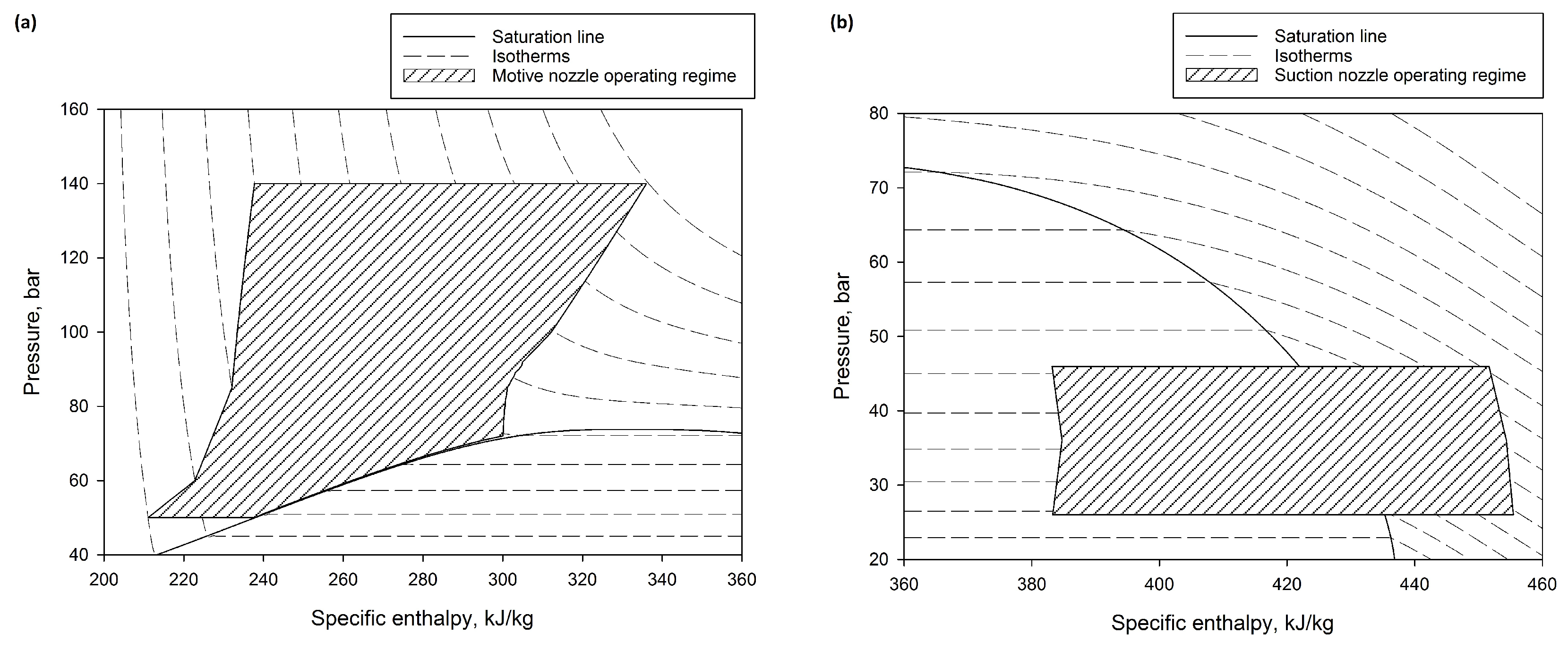
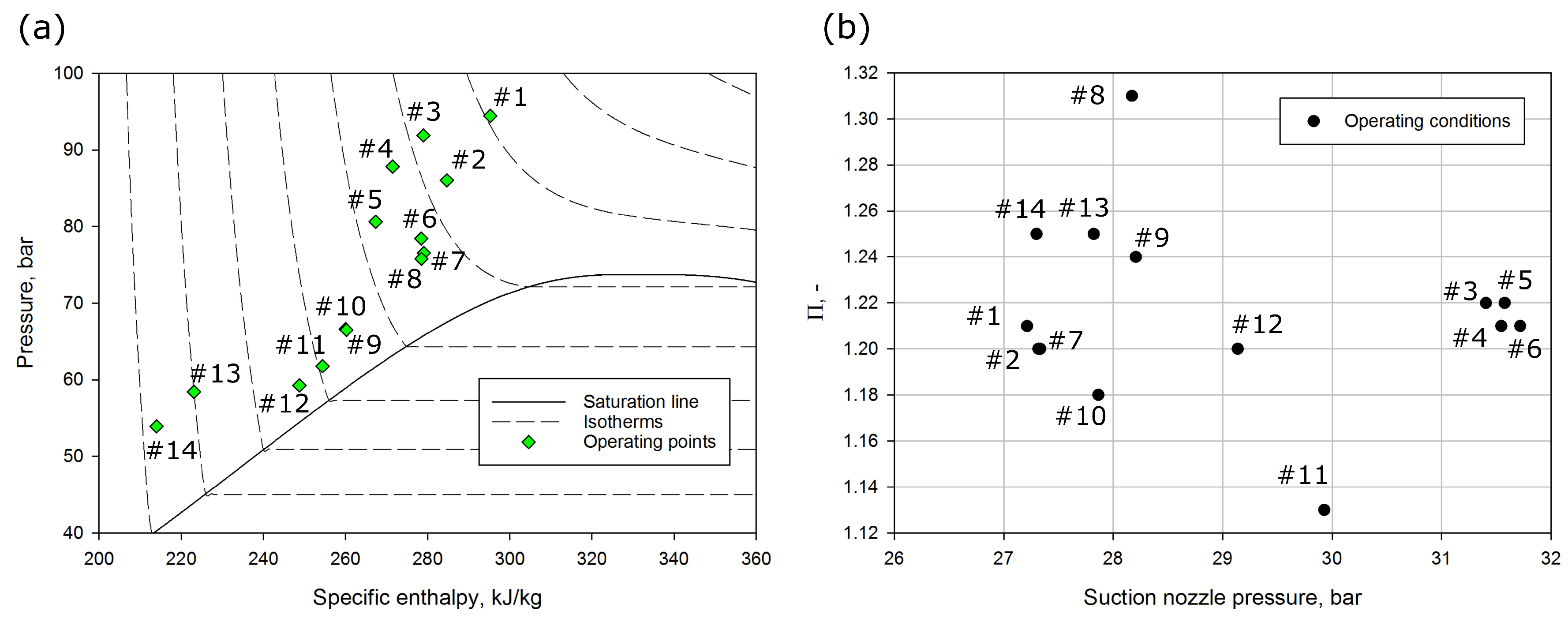
In order to compare all three investigated mathematical models of the R744 two-phase ejector, the accuracy of the motive nozzle and the suction nozzle MFRs under different operating conditions (that are typical for refrigeration and air-conditioning applications) are tested. The set of the operating conditions is shown in
Table 2. The investigated points were selected from an experimental test campaign carried out at the R744 multi-ejector test rig at the SINTEF/NTNU laboratory in Trondheim [
33]. Moreover, the selected points were previously used to validate the HRM CFD model in [
26]. The motive nozzle conditions were defined from approximately 54 bar up to approximately 95 bar. Therefore, the accuracy comparison of the ejector models MFRs was defined for ejector utilisation under subcritical conditions, close to the critical point, and transcritical conditions. Moreover, the motive nozzle temperature varied from approximately 279 K to over 308 K. The suction nozzle conditions were defined for refrigeration and air-conditioning applications. Hence, the suction nozzle pressure varied from approximately 27 bar up to approximately 32 bar and the temperature was in the range from approximately 273 K to below 280 K. The outlet pressure was from 32 bar to approximately 39 bar for the evaluation of ejector performance at different ratios of pressure between the outlet and the suction nozzle.
All selected operating conditions are also presented in
Figure 5 in a pressure-specific enthalpy diagram of R744. In the same figure, the pressure ratio parameter is shown relative to the suction nozzle pressure. The different sub-cooling degrees under subcritical conditions and the different temperatures under transcritical conditions of the motive nozzle were set for validation. The pressure ratio varied from 1.12 to 1.32 due to the pressure difference between the outlet and the suction nozzle. In addition, different pressure ratios were reached at similar suction nozzle conditions, which were strongly related to the value of the mass entrainment ratio.
Table 3 presents the comparison results of each two-phase ejector model together with the experimental data. The relative differences between the motive nozzle and the suction nozzle MFRs together with the mass entrainment ratio were set to evaluate the accuracy of the investigated ejector models. According to the experimental data, the motive nozzle MFR varied from approximately 0.07 kg·s
to over 0.1 kg·s
and the suction nozzle MFR was in the range from approximately 0.01 kg·s
to 0.035 kg·s
. As the result of both MFRs, the mass entrainment ratio was below 0.42.
The 0D model using a constant value of ejector efficiency obtained a motive nozzle MFR discrepancy from approximately % under subcritical conditions to 27% under transcritical conditions. The suction nozzle MFR accuracy of the 0D model was in the range from approximately % to 36.5%. As a result, for the MFR predictions of both nozzles, the relative difference of the mass entertainment ratio varied from % to over 47%.
A similar accuracy was reached by the 1D model due to similar calculations of the motive nozzle MFR using Equation (
4). The 1D ejector model predicted the suction nozzle MFR with an accuracy in the range from approximately
% to below 60%. Moreover, the mass entrainment ratio discrepancy of this model was from approximately
% to over 72%.
The hybrid ROM obtained very high accuracy of the motive nozzle MFR below 1%, which confirmed very good agreement of the results given by the hybrid ROM compared to the experimental data. Very low discrepancy in the hybrid ROM was reached for the suction nozzle MFR and the mass entrainment ratio for all investigated points.
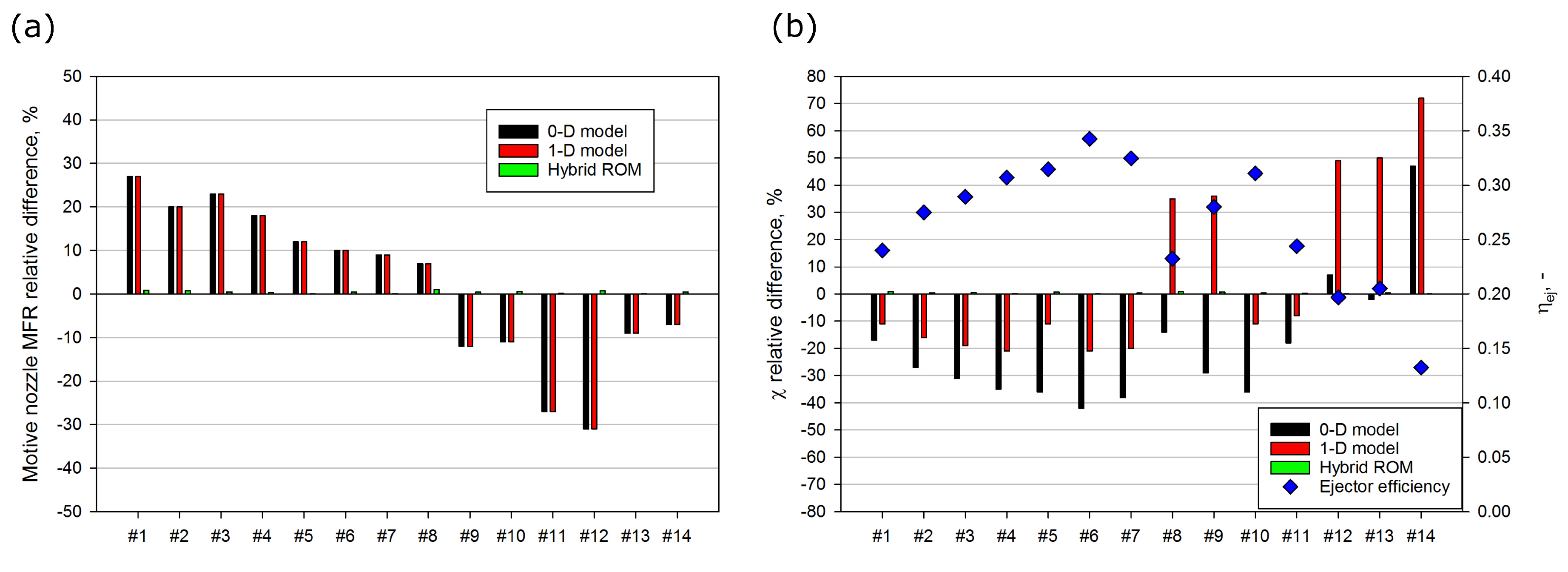
Figure 6 presents the relative difference between numerical result produced by each R744 two-phase ejector model and appropriate measurement under all selected operating conditions. The 0D and 1D models reached a motive nozzle MFR relative difference within ±10% for operating conditions close to the critical point (#5
8) and for a motive nozzle pressure below 60 bar at #13 and #14, which is shown in
Figure 6a. Moreover, both ejector models overestimated the motive nozzle MFR under transcritical conditions and underestimated it under subcritical conditions. Hence, the higher inaccuracy represented by the relative difference for the motive nozzle MFR by the 0D and 1D ejector models was strongly related to the suction nozzle MFR and the mass entrainment ratio predictions. The motive nozzle MFR relative difference shown in
Figure 6a confirmed the better agreement of the hybrid ROM. The relative difference for the mass entrainment ratio is shown in
Figure 6b together with the ejector efficiency given by the experimental data. The 0D model reached the best agreement close to the ejector efficiency of 0.2 at #12 and #13 due to the assumed constant efficiency based on previous literature [
28]. However, the efficiency varied from approximately 0.14 to almost 0.35, which caused underestimation of the mass entrainment ratio for ejector efficiencies above 20% and overestimation for efficiencies below 20% for the 0D model. The 1D model obtained an underestimated mass entrainment ratio under transcritical conditions (#1
7), and it also obtained a very low pressure ratio at #10 and #11. The very high pressure ratio above 1.24 caused significant overestimation of the mass entrainment ratio, and the inaccuracy was above 30% for #8 and #9 and for motive nozzle pressure below 60 bar (#12
14). The hybrid ROM reached satisfactory agreement at each investigated point due to the hybrid combination of the CFD results and the experimental data.
The comparison discussed above proved high accuracy of the hybrid ROM for a very wide operating region. Therefore, the performance evaluation of the R744 two-phase ejector implemented in the refrigeration system using the hybrid ROM allowed ejector efficiency values close to those recorded during experimental tests under different ambient conditions.
6. Dynamic Simulations of the R744 Two-Phase Ejector Integrated With the Refrigeration System
The implementation of the object-oriented two-phase ejector hybrid ROM to the R744 refrigeration system also allowed dynamic simulations of the ejector-based system for different ambient conditions and cooling demands. Moreover, detailed information about the ejector performance during continuous utilisation was observed. Dynamic investigation of the R744 refrigeration system equipped with the two-phase ejector was completed in three different regions characterised by different ambient temperature ranges: Mediterranean zone (measured in Naples, Italy), South America zone (measured in Rio de Janeiro, Brazil) and South Asia zone (measured in New Delhi, India). The weather data were obtained from the free open-source EnergyPlus platform [
37]. The analysis was performed during the summer campaign over a period of two months, which is equivalent to approximately 1488 h. Moreover, the dynamic simulations were done with a time interval of 60 s to evaluate the reaction of the system’s operating conditions to the ambient variation.
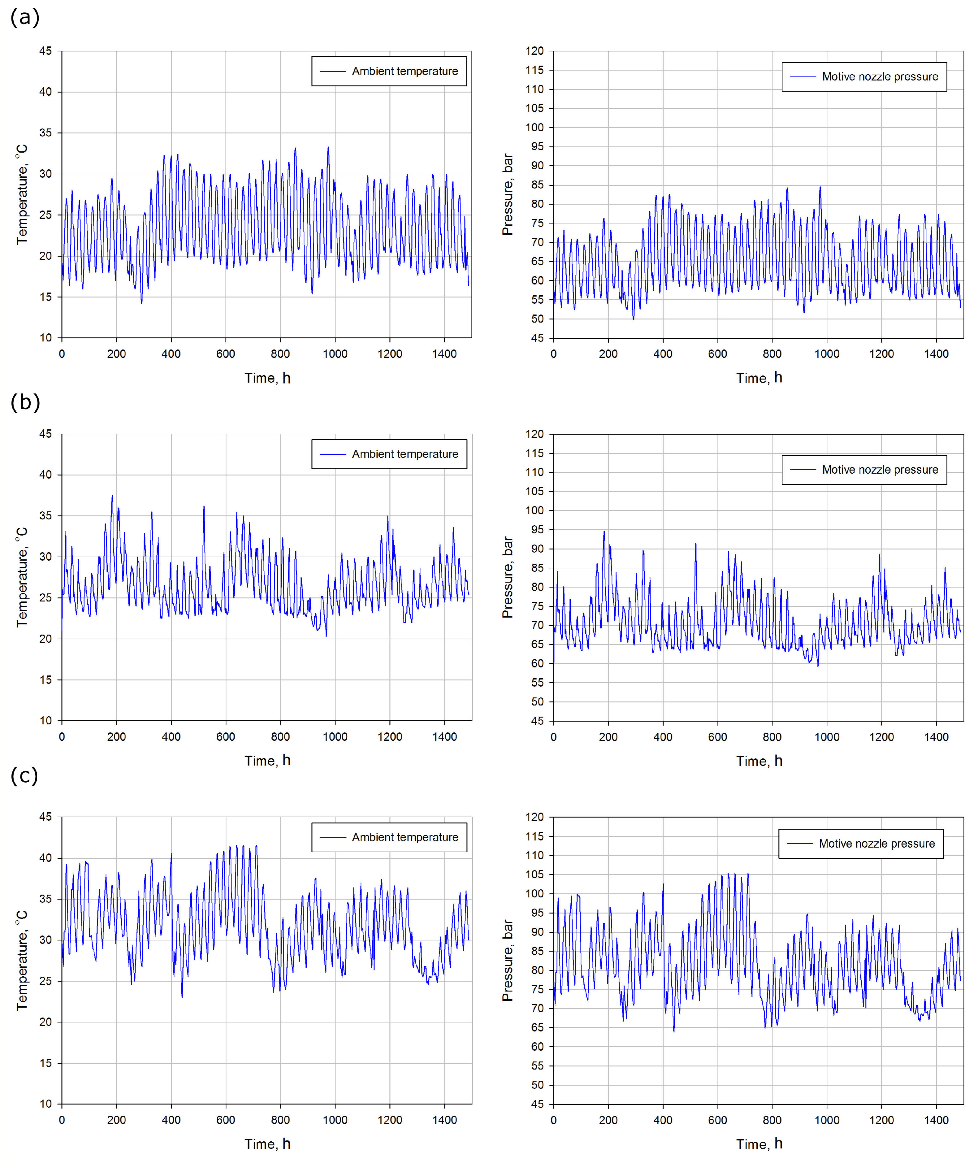
Figure 8 presents the ambient temperature and the motive nozzle pressure variations during the investigated campaign at each selected climate region. The motive nozzle pressure was strongly related to the gas cooler outlet pressure; therefore, the relationship between the ambient conditions and the motive nozzle pressure controls the ejector and gas cooler utilisation. The ambient temperature in the Mediterranean region shown in
Figure 8a was in the range from approximately 15
C to below 34
C. Hence, the ejector was utilised under subcritical conditions during the summer campaign. However, the R744 refrigeration system reached a maximum pressure of 85 bar at two temperature peaks halfway through the summer campaign. In
Figure 8b, the ambient temperature is shown to vary from 20
C to approximately 37
C for the South America region; this variation is smaller than the temperature variation shown in
Figure 8a. Hence, transcritical conditions were reached for approximately 50% of time of the investigated campaign. Moreover, the lowest motive nozzle pressure of 60 bar for the South America region was approximately 10 bar higher than the lowest pressure obtained in the Mediterranean region. A highest ambient temperature was reached for a long period of time in the South Asia region, as presented in
Figure 8c. The temperature varied from 24
C to approximately 42
C. As a result of the high ambient conditions, the two-phase ejector was utilised for transcritical conditions for most of the investigated time. Moreover, the motive nozzle pressure was in the range from 65 bar to over 105 bar, which was strongly related to the system performance as well as the ejector efficiency.
The variations in the motive nozzle conditions in terms of the varied ambient conditions were strongly related to the ejector performance. Moreover, the poor control of the two-phase ejector caused the ejector to have low efficiency, and the system control was far from the optimum COP. One of the most important parameters during ejector operation is the pressure ratio parameter due to the liquid receiver pressure control. Therefore, investigation of the ejector performance during the summer campaign in different regions was done for three different pressure ratios. In addition, the R744 ejector-based system was utilised in a refrigeration application, and the MT evaporator pressure was set to approximately 28 bar with the defined superheat degree of 15 K.
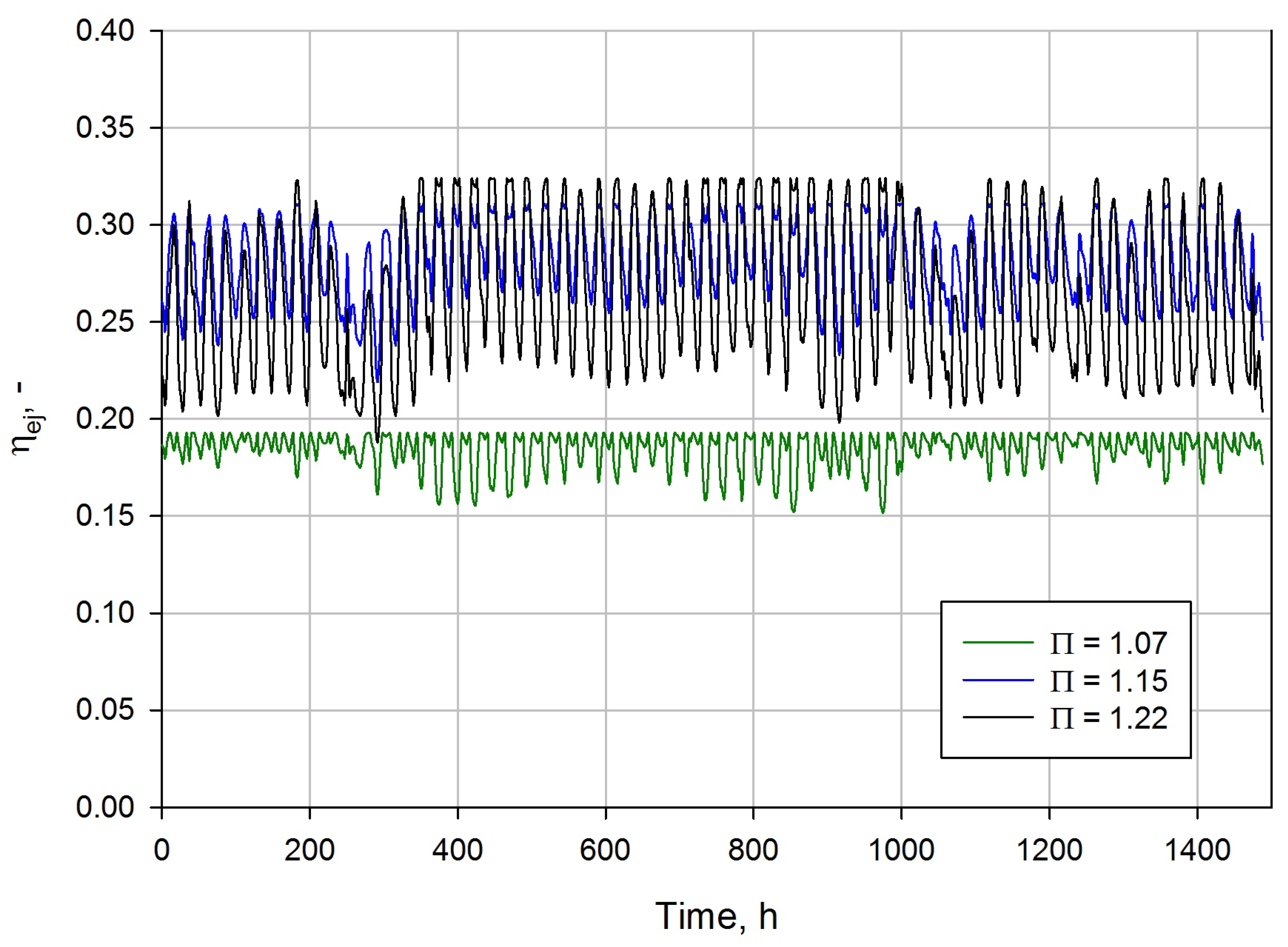
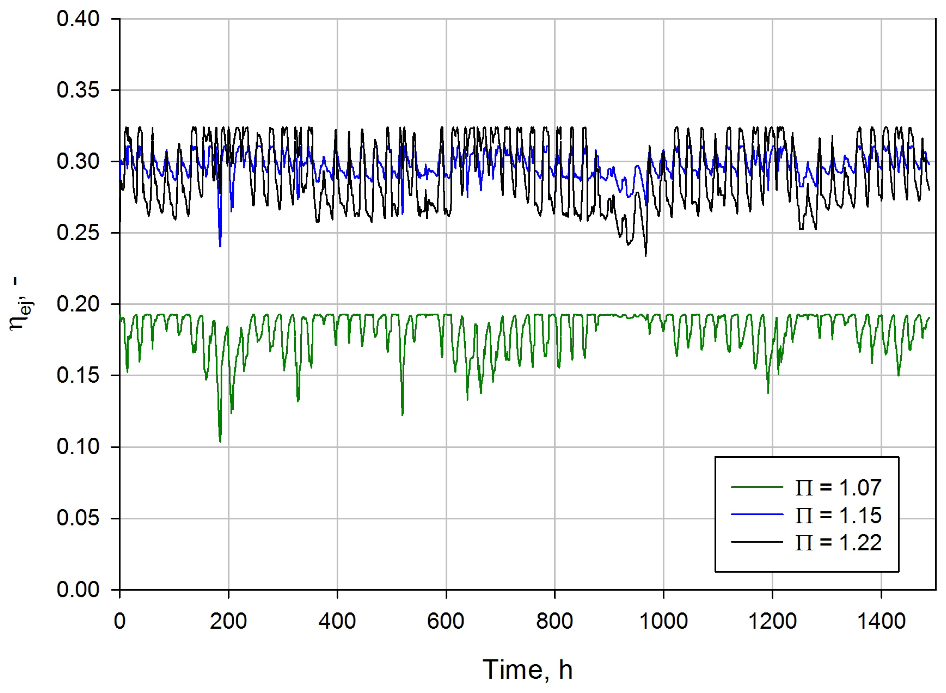
Figure 9 presents the ejector efficiency for different pressure ratios during the investigation in the Mediterranean region. The lowest pressure ratio of 1.07 was linked to the lowest efficiency of below 0.2 due to the low potential to recover the expansion work. The small value of the pressure ratio caused the ejector to be more stabilised and the efficiency variation was approximately 0.03. An increase in the pressure ratio increased the oscillations of the ejector performance. However, the two-phase ejector with the pressure ratio of 1.15 resulted in an ejector efficiency in the range from approximately 0.22 to below 0.31. The efficiency drop was reached after approximately 300 h as the effect of the significant ambient temperature decreased up to 15
C. The highest efficiency of the two-phase ejector of approximately 0.33 was obtained for pressure ratio of 1.22. However, the ejector efficiency dropped down to 0.19 following a decrease in the motive nozzle pressure. Hence, the pressure ratio should be related to the ambient conditions and the cooling demand to maintain the high efficiency during temperature decrease.
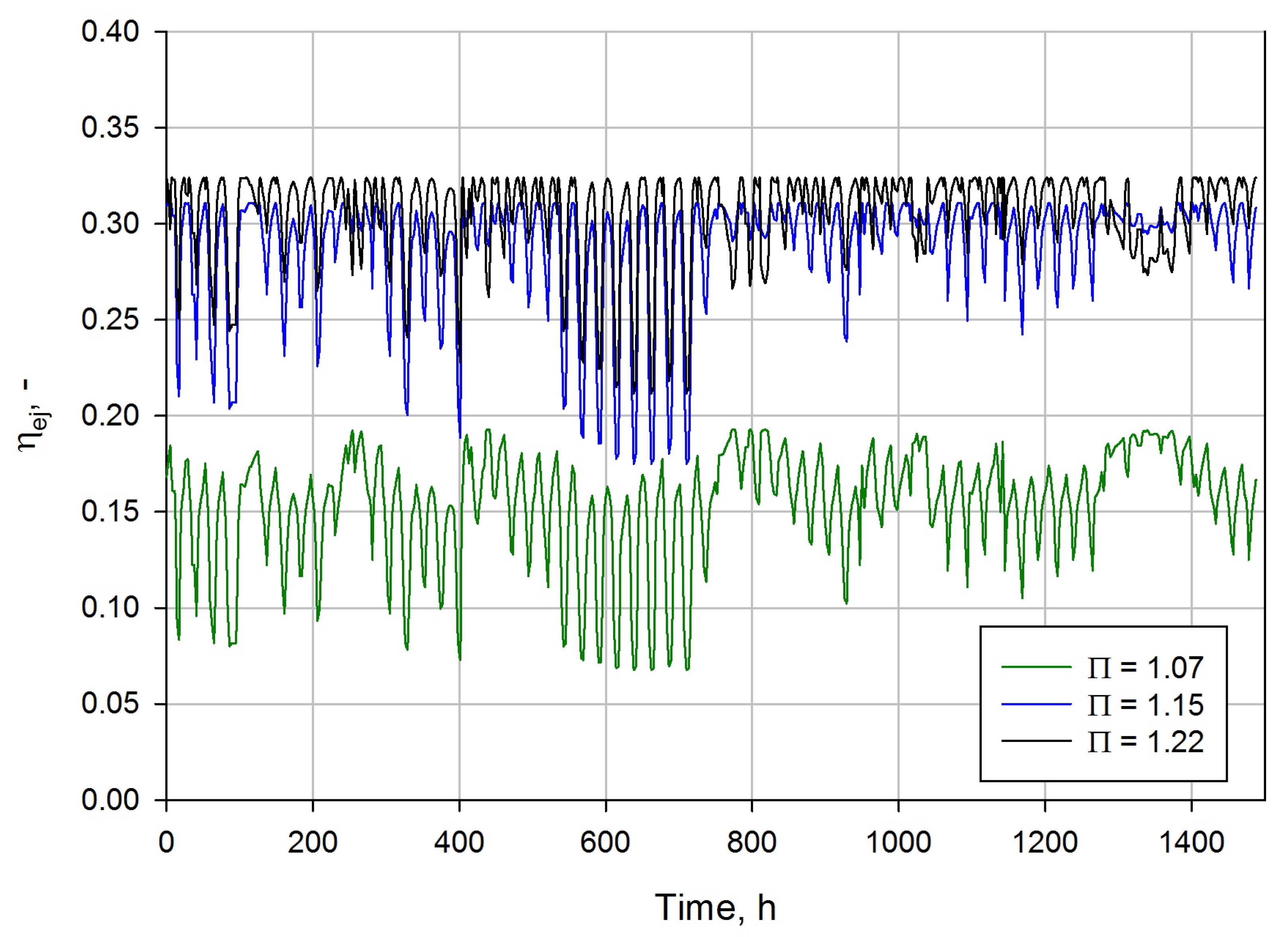
The performance of the R744 two-phase ejector during the summer campaign in the South America region confirmed the possibility of controlling the ejector in an efficient way, which is shown in
Figure 10. Similar to the results presented in
Figure 9, the ejector was utilised at the lowest pressure ratio of 1.07 which resulted in the lowest efficiency found during the investigated campaign of below 0.2. Moreover, higher ambient temperatures above 35
C caused a higher efficiency drop to almost 0.1. The significant efficiency improvement was observed for higher pressure ratios. The two-phase ejector with a pressure ratio of 1.15 reached an efficiency in the range from approximately 0.25 to 0.31. In addition, the ejector at a pressure ratio of 1.15 was more stable compared with the ejector at a pressure ratio of 1.22. The highest ejector efficiency value of approximately 0.33 was obtained at the highest pressure ratio of 1.22, although the ejector performance dropped down to approximately 0.24. Therefore, the possibility to define the ejector operating conditions during continuous work allows stable and high performance of the two-phase ejector to be achieved.
Figure 11 presents the ejector efficiency for different pressure ratios during the investigated campaign in the South Asia region. The worst ejector performance was noticed for the pressure ratio of 1.07, which agrees with the analyses performed for the Mediterranean region and South America region. Moreover, the very high ambient temperature of above 40
C strongly influenced the efficiency degradation for the pressure ratio of 1.07. As for the results for highly varied ambient conditions, the two-phase ejector with the pressure ratio of 1.07 obtained an efficiency in the range from approximately 0.07 to below 0.2. An increase in the pressure ratio of up to 1.15 significantly improved the ejector efficiency. However, similar performance degradation was observed for very high ambient temperatures for which the efficiency varied from approximately 0.17 to 0.31. The highest value of the pressure ratio of 1.22 caused the best performance for most of the investigated time during the summer campaign. The two-phase ejector reached efficiency in the range from 0.2 up to 0.33. Further improvement of the ejector performance at very high ambient temperatures and a motive nozzle pressure above 100 bar can be achieved by an increase in the pressure ratio. Hence, the R744 two-phase ejector should be controlled to optimise the ejector efficiency by proper setting of the pressure ratio for a specified application.
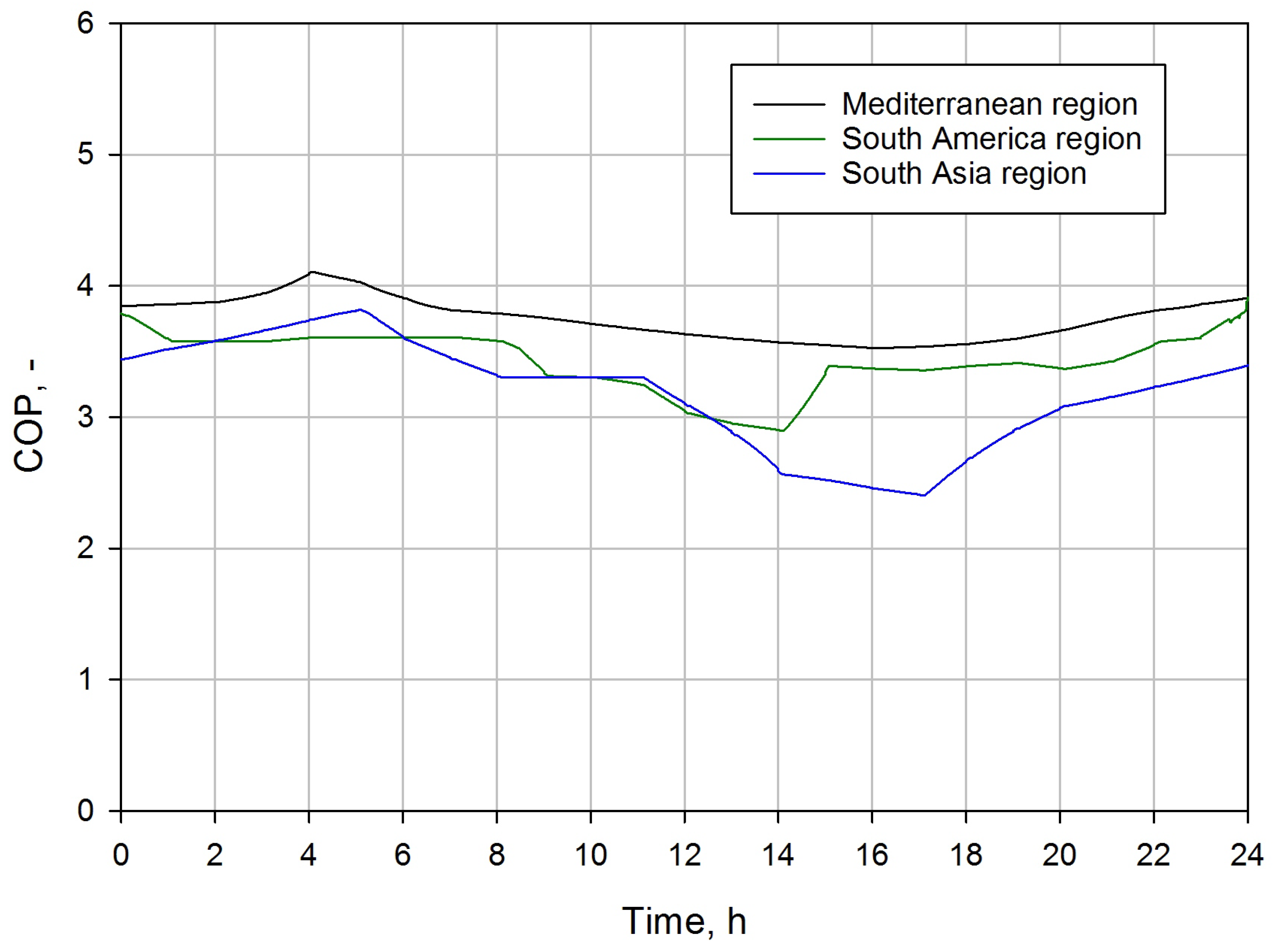
The characteristics of the ejector performance during the summer campaign in different hot climate zones are strongly related to the COP value of the system, especially during work in the daytime. Hence,
Figure 12 presents the COP comparison for the R744 ejector-based system at different climate regions for 24 h during the summer campaign. The pressure ratio was set to 1.22 to achieve the highest ejector efficiency. The R744 refrigeration system equipped with the two-phase ejector obtained the highest COP values of above 3.5 in the Mediterranean region due to the subcritical operation for most of the investigated time according to
Figure 8a. The lowest COP during the day was observed in the afternoon at approximately 4:00 p.m., whereas the highest peak of COP was reached at 4:00 a.m. The R744 ejector-based system experienced a lower COP in the South America region due to the higher daily ambient temperature, which is shown in
Figure 8b. The significant COP drop below 3.0 was observed at approximately 2:00 p.m. The lowest COP of the R744 refrigeration system was obtained for the South Asia climate zone due to the very high ambient temperature above 40
C. Therefore, the COP dropped from approximately 3.8 to less than 2.5, although the energy performance of the R744 ejector-based system was higher between the second hour and sixth hour as a result of the ejector performance. The significant difference in COP between the selected climate regions forced the control process of the R744 refrigeration system to be improved to operate close to the optimum COP.
7. Conclusions
The object-oriented hybrid ROM of the R744 two-phase ejector was developed for dynamic simulations. The proposed model was compared with two simpler mathematical approaches of the ejector that have commonly been used in the literature for refrigeration system investigations. Moreover, a dynamic simulation of the R744 refrigeration system equipped with the two-phase ejector for different climate zones was performed to evaluate the ejector and the system’s performance.
The object-oriented hybrid ROM was implemented in OpenModelica free software using the external function built in C-code programming. The proposed model allowed the evaluation of ejector performance under arbitrary operating conditions within the operational envelope defined for the HVAC&R supermarket system. Apart from the hybrid ROM, the 0D ejector model assumed a constant efficiency, and the 1D ejector model with the assumption of homogeneous equilibrium two-phase fluid flow was implemented for the comparison of different mathematical approaches to describe ejector performance. In comparison, procedure accuracy, represented by the relative difference between numerical result produced by each two-phase ejector model and appropriate experimental measurement, is determined. The 0D model obtained satisfactory prediction of both nozzles’ MFRs only at values close to the assumed ejector efficiency. The more accurate 1D model reached an accuracy level within ±10% for motive nozzle pressures close to the critical point. However, very high discrepancy was observed for high pressure ratios. The hybrid ROM obtained the best accuracy for all investigated points due to the hybrid combination of the experimental data with the CFD results that was used to build the ROM basis. Therefore, the integration of the hybrid ROM allowed the evaluation of the R744 refrigeration system equipped with the designed two-phase ejector.
The investigation of the ejector performance during the summer campaign demonstrates the variation in the work of the ejector. Three different climate zones were selected for investigation: a Mediterranean region (Italy), a South American region (Brazil), and a South Asian region (India). The R744 two-phase ejector was mostly utilised under subcritical conditions in the Mediterranean climate zone. Transcritical conditions were achieved for most of the summer campaign for zones with higher ambient temperatures in South America above 30 C and in South Asia above 40 C. The ejector efficiency is strongly related to the pressure ratio, especially during conditions of significant temperature difference. An increase in the pressure ratio allowed a high efficiency of above 0.2 up to 0.35 to be maintained. However, the pressure ratio should be well controlled to achieve an ejector performance close to the optimum during system utilisation. According to the results, the pressure ratio of 1.15 allowed the greatest stabilisation of the system.
The evaluation of energy performance of the R744 refrigeration system equipped with the two-phase ejector confirmed the influence of the high ambient temperature on COP. The highest COP value was obtained in the Mediterranean region as a result of the system operating in subcritical conditions for most of the investigated time. An increase in the ambient temperature generally caused the COP degradation. Hence, the lowest COP value was observed in the South Asia climate zone. Energy performance improvement for the R744 ejector-based system can be achieved by optimisation of the liquid receiver pressure and outlet conditions of the gas cooler as well as the internal heat exchanger.

 ,
, 


