1. Introduction
Wireless Power Transfer (WPT) technology has lately gained increasing attention as an alternative way to transmit power with respect to a cabled connection, see for instance [
1,
2,
3]. In particular, applications for small portable consumer electronic devices are already available on the market (i.e., cellular phones, electric tooth brushes and the Qi standard, etc.) while high power applications are still the object of research, study and prototyping (charging of electric vehicles or hybrid vehicles is an example). In the last decade, Power Line Communication (PLC) has been recognised as a viable option for broadband communications, and it can compete with other, and more diffused, technologies when operating in specific environments. PLC technology uses power cables to transmit high speed data; in fact it uses the power grid, that is designed to carry voltages and currents at the mains frequency (typically at 50/60 Hz) to transmit data at much higher frequencies, that are now up to a tenth of MHz, in the most common commercial products. Domestic applications of PLC technology are quite widely diffused, while, on a larger scale, PLC communication is now considered one of the main possibilities to transmit data in a smart grid environment (when, for instance, long distances do not allow wireless data transmission). Recently, the PLC technology has been proposed to substitute part of the cable harness in electric vehicles [
4,
5,
6]. These two technologies are apparently colliding, since WPT transfers power wirelessly while PLC transmits data on a cabled connection originally designed for power. This has led the authors to the idea that a full integration between WPT and PLC could be a solution allowing the use of WPT without the need for changes to a pre-existing PLC system. In [
7] a feasibility study of such a system is proposed, in which a preliminary logic outline of the whole system is shown, and the evaluation of the available channel capacity is performed based on a typical four-coils system. In [
8], an optimization procedure performed on the lumped equivalent circuit is presented, showing that such a system can be properly designed taking into account both power and data transmission requirements. In addition, in [
9] the full system (with coils and filters) was designed and built showing the actual feasibility of the proposal; in particular, ref. [
9] is specifically referring to a two-coils WPT system.
In this contribution the authors investigate for the first time the possibility of using the loops and the coils (respectively called also “outer coils” and “inner coils”) of a four coils system as different access points: while the power generator and load are respectively connected to the drive and load loop, the data modems are now connected between the coils. This completely new concept, under specific circumstances, can guarantee a wider communication band, hence better communication performances.
In [
9], the two coils system has been designed to transmit power at the resonant frequency of
MHz, that is often related to low power applications such as energy harvesting devices etc., see for instance [
10]. In this paper the system is designed to transmit power at a frequency of hundreds of kHz, typical of high power applications such as battery charging of electric vehicles, as shown in [
11]. In addition, the frequency range considered in this paper is typical of narrow band (NB) PLC, in contrast to broad band PLC that uses tens of MHz. Then, this work shows for the first time that NB-PLC and WPT can coexist and share the same medium. The proposed system is of great potential and can be the key point in which both data and power should be transferred, for instance in a Battery Management System for electric vehicles [
12] or in domestic applications [
13]. The paper is organized as follows: in
Section 2 the rationale behind the main idea is described; in
Section 3 it is described how the system has been built according to analytical relations; in
Section 4 the theoretical analysis relative to the optimal relation between resonant frequency, distance and load is obtained, while
Section 5 presents the analytical and theoretical results for the proposed system.
2. WPT System with Multiple Data Access
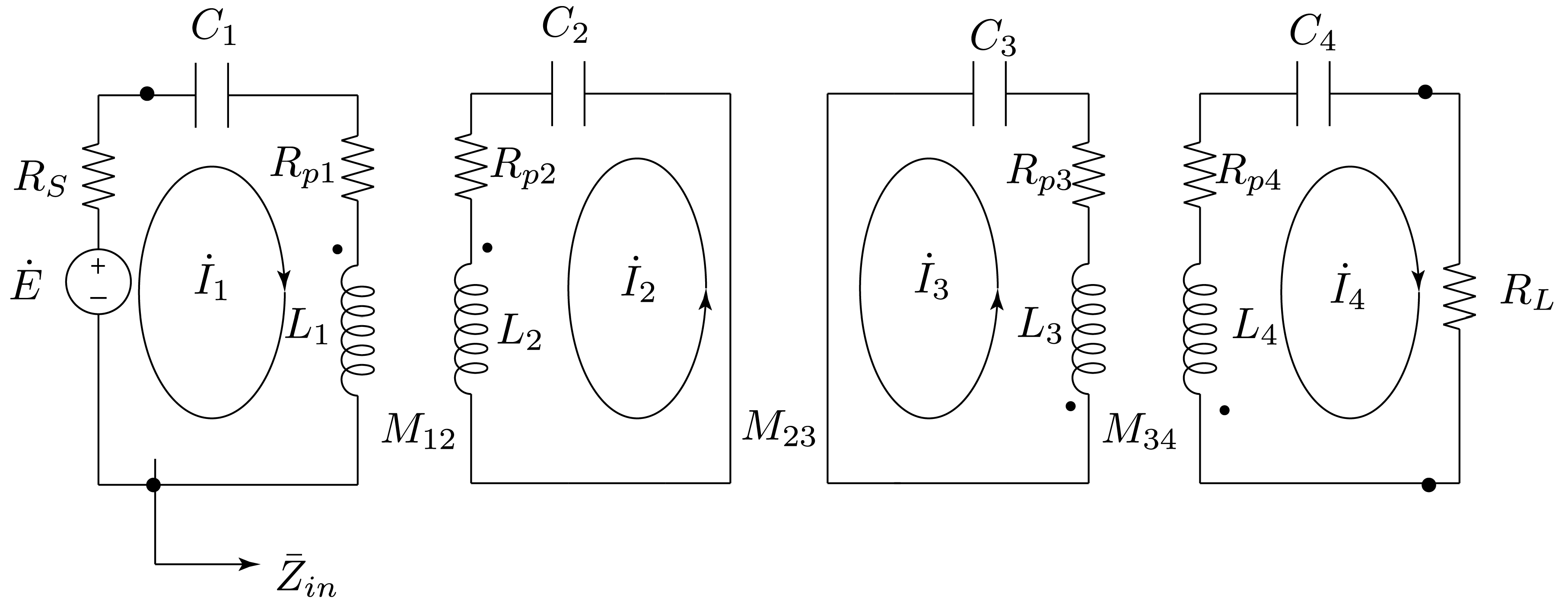
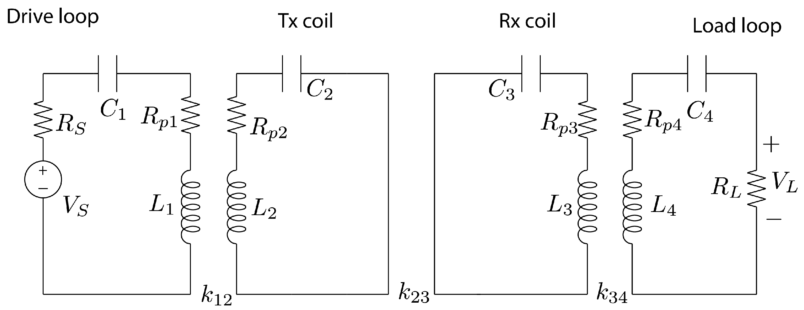
Figure 1 shows the typical equivalent circuit of the non radiative four coils WPT system with the so called drive and load loops (where the source and the load are connected) and the transmitting and receiving coils, that are basically used as repeaters in order to increase the power transmission distance (reducing
) retaining maximum power transfer. The inductances
and
represent the transmitting and receiving coils, while
and
represent the drive loop and load loop inductors respectively. The resistances
represent the winding resistances of the corresponding inductor and are, as a matter of fact, parasitic elements. The mutual inductance
represents the coupling between the inductors
and
(with coupling coefficient
), while the capacitors
are designed to resonate with the corresponding inductor at the resonance frequency. The coupling factor
depends on the distance between the transmitting and receiving coils, which is a fundamental design parameter. In this scheme, parasitic capacitances (basically given by the turn to turn capacitance of each inductor) are not represented, since they are grouped together with the capacitances
(of each inductor). Usually the transmitting and receiving coil (also called “inner coils” due to the fact that are represented in between the other two inductors) have no access point and are often mounted on the same equipment as the relative loop.
The use of a lumped equivalent circuit to represent a WPT system is a common way to understand and design it; speaking of frequencies in the range of kHz to few MHz, we are in the field of non radiative WPT systems, and this approach will be used throughout the paper.
When additional data transfer capabilities (with the motivation of interfacing to a PLC system) have been added to the WPT system, the most logical approach was to use the same terminals of the power transfer: this is trivial for a two-coils system, and was the first choice for a four-coils system ([
7,
8,
9]).
A first theoretical study regarding the use of different access points for four-coils WPT systems has been performed in [
14]: two different circuits have been analyzed as shown in
Figure 2 and
Figure 3. The circuit of
Figure 1 has been modified in order to include additional filters that are actually required in the proposed combined system WPT-PLC: they should prevent power from flowing through the PLC modem (to avoid damages) and guarantee optimal coupling between the modem and the WPT system, possibly not affecting the power channel in terms of efficiency.
The system in
Figure 2 is basically the one described in [
9], with the parallel resonant circuit
that resonates at the frequency of the power signal, hence operating as an open circuit. In this way the power signal (generated by
and received by
) does not flow into the PLC modem
. On the contrary, the wideband data signal generated by
and received by
is not affected by the higher magnitude power signal.
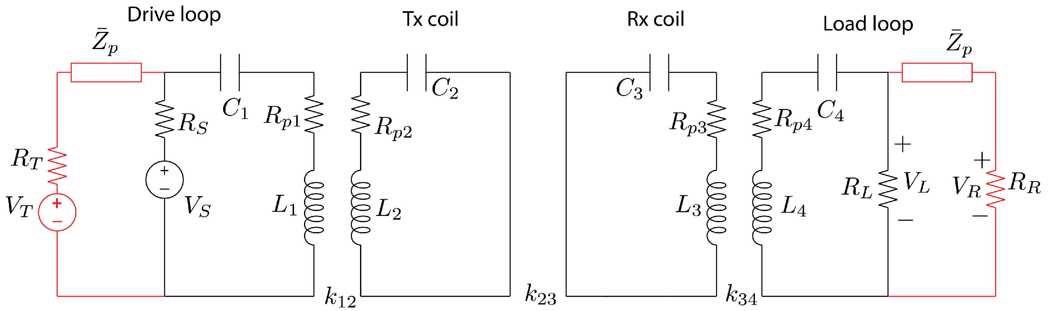
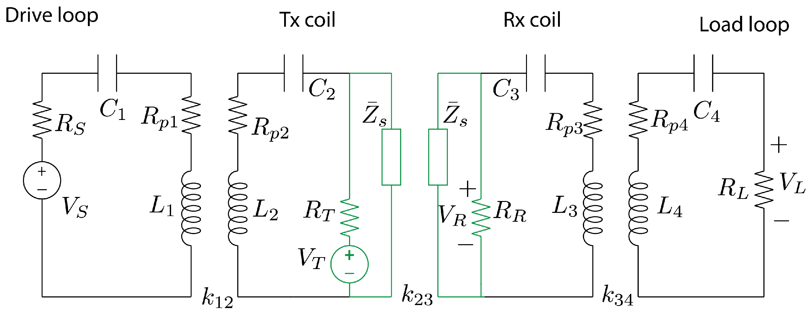
Figure 3 shows the new architecture object of this theoretical and practical study: data communication is performed between the inner coils, with the addition of the
series resonant circuit; this series LC filter behaves as a short circuit at the power frequency, basically eliminating from the inner loops the modem and the transmitting and receiving loads (respectively
,
,
): in this way the power signal does not flow through the PLC modem and it is not dissipated into the receiving and transmitting resistances. At frequencies different from
, data signal can flow between the inner coils.
In this paper the authors have considered, for the sake of simplicity, second order parallel or series LC resonant circuits resonating at the power frequency
. Despite the simplicity of this approach, the results obtained clearly indicate that good performances can be achieved. Given the equivalent circuits shown above, it is possible to derive the analytical transfer functions both for power and data transfer: Equations (
A1) and (
A2) are relative to the transfer function of the power channel of the circuit in
Figure 2, while (
A3) and (
A4) are relative to the transfer function of the data channel in the same circuit. In the same way, Equations (
A5) and (
A6) are relative to the transfer function of the power channel of the circuit in
Figure 3, while (
A7) and (
A8) are relative to transfer function of the data channel in the same circuit. These expressions will be used in
Section 5 and compared with experimental results.
In [
14] a theoretical analysis has been performed on the two circuits with a specific set of circuit’s parameters values (which were originally given in [
15]); these theoretical results show that, in this specific case, the channel capacity in terms of bit rate is higher when data is transmitted between the inner coils. Far from being an exhaustive analysis, these results have led the authors to perform additional investigations and experimental validation, that are reported in this paper.
3. Coil Design
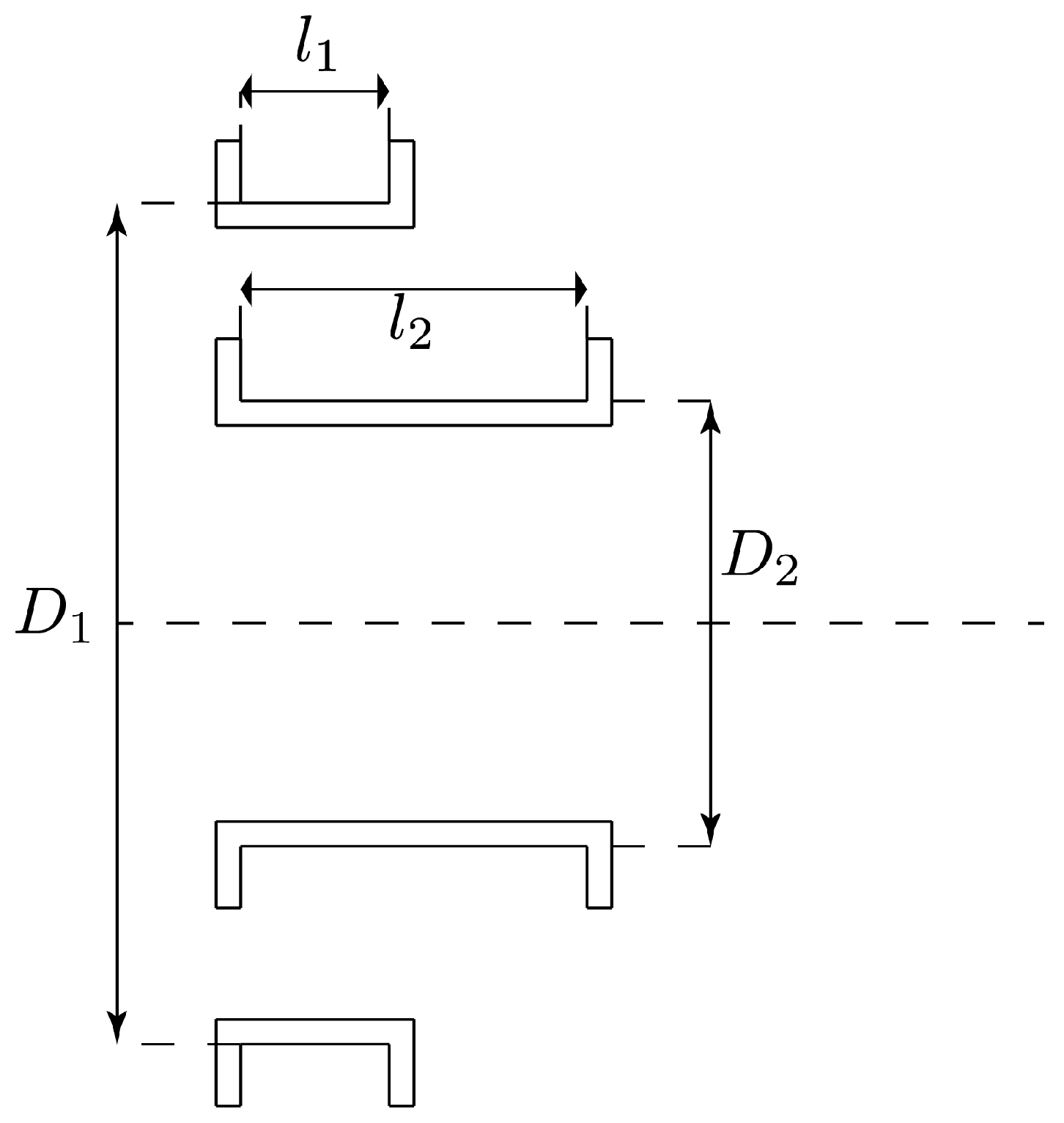
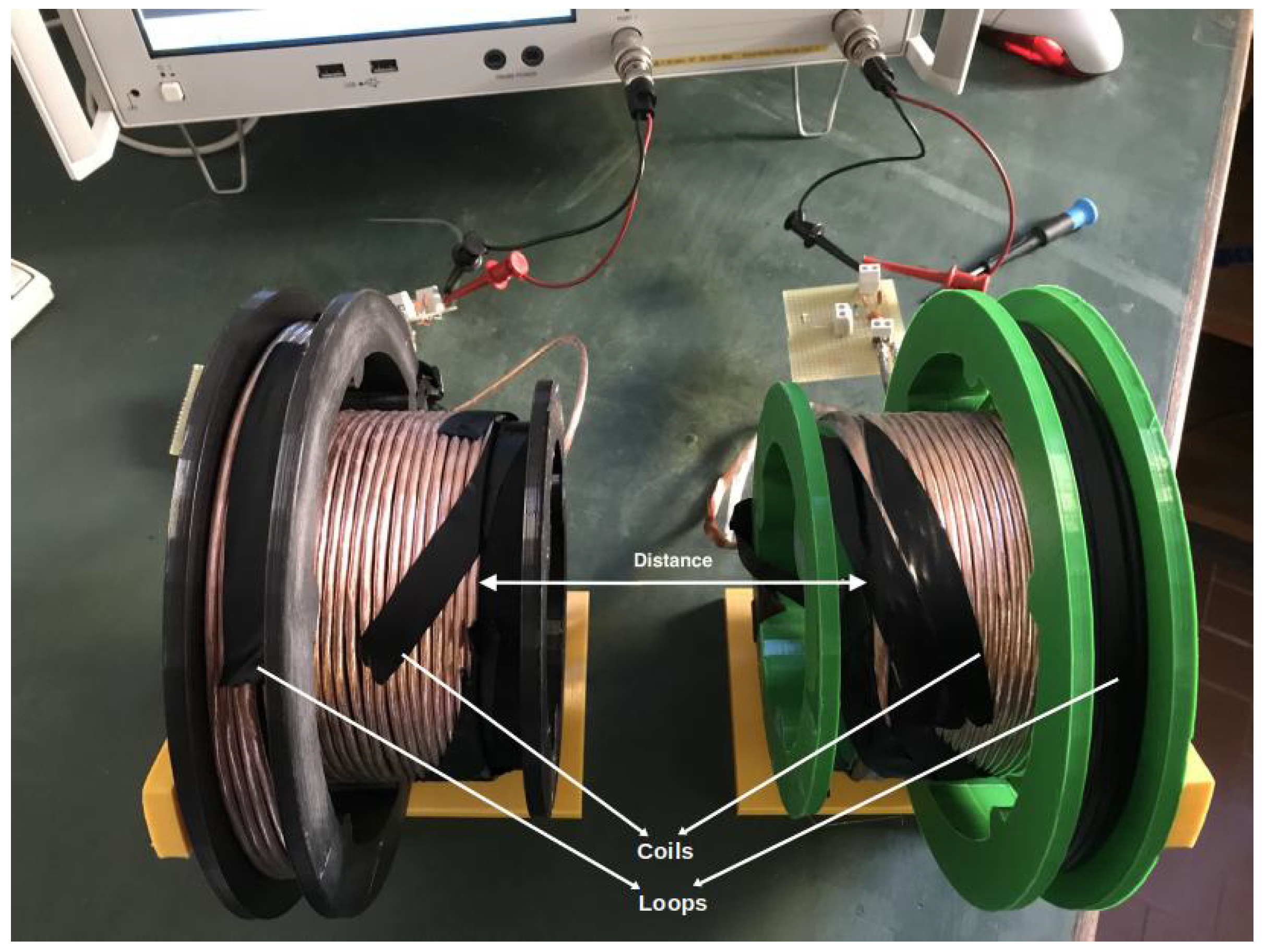
The design of the WPT system has been performed taking into account the working frequencies and coils dimensions, allowing a simple experimental setup. In four coils WPT systems, the loop (e.g., power access point) and the short circuited coil are a unique system in which their mutual distance is kept as constant; in most cases, two twin loop-coil system are used to create a four coils WPT system.
Figure 4 shows the outline of a loop-coils set, in which the dimensions are relative to the coils support and are reported in
Table 1.
In order to reduce the resistance due to skin and proximity effect, a copper Litz wire has been used: the chosen wire is characterized by 600 strands, each of them having a diameter of
mm; considering that skin depth at the frequency
MHz is about
m, the chosen wire works well for power frequencies of the order of a few MHz. The coils have been realized as single layer coils, whose value of self inductance has been calculated according to [
16] and the self capacitance according to [
17]; these values are reported in
Table 2.
The coupling coefficient (hence the mutual inductance) for the configuration shown in
Figure 4 has been consequently calculated according to [
18], resulting in the following values:
H,
.
The four coils system is composed by two loop-coil sets facing each other; the coupling coefficient
between the two coils have been calculated for distances varying in the range between 3 cm and 23 cm ([
18]); some of them are reported in
Table 3. It is worth noting that the coupling between loop and coil belonging to different sets (i.e.,
and
) have been neglected, as it is usually done in such cases. This assumption is justified by analyzing the distance between the left loop and the right coil (considering the dimensions shown in
Figure 4) and the results in
Table 3:
and
would be much lower than the other coefficients.
In order to validate the design procedure, the self inductances have been measured with a Vector Network Analyser (VNA) which allows verifying the frequency behavior of the system as well. The measured values of the inductances are
H and
H showing a good agreement with the design parameters which are listed in
Table 2. The AC resistance of the coils were also measured, obtaining
m
and
m
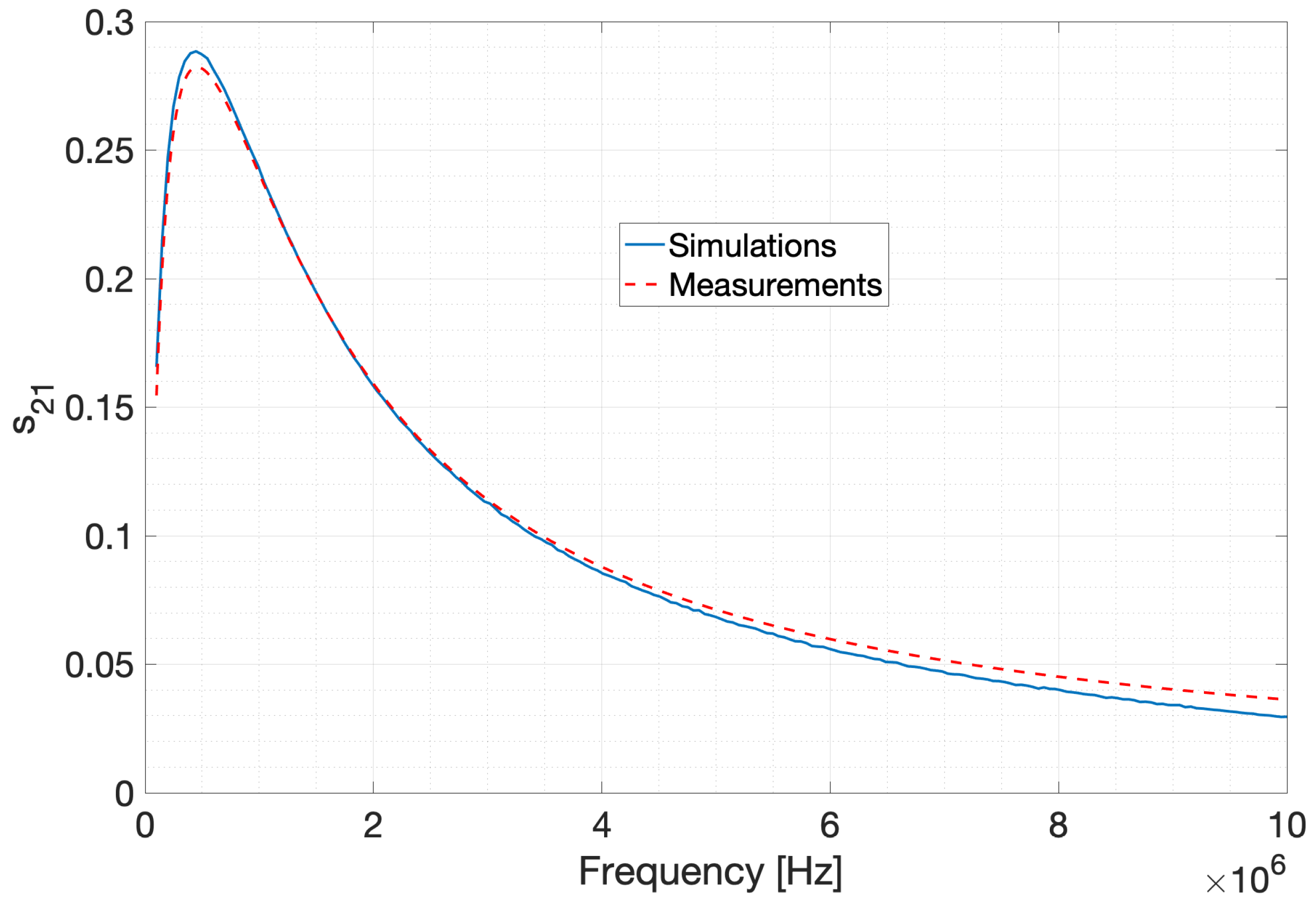
. The setup of
Figure 4 has been experimentally implemented as depicted in
Figure 5 and the two coils have been connected to the two ports of the VNA, measuring the frequency behavior of the scattering parameter
(also called transmission coefficient).
Figure 6 shows the comparison between measurement and analytical calculations (not reported here for a two coils system for the sake of conciseness): as described, the system realized matches with very good accuracy the design criteria.
4. Four-Coils WPT Input Impedance System Modeling
This section focuses on the modeling of a four coils WPT system, in particular we first recall the equations of the circuit, then we derive an exact analytical expression of the input impedance of the four coils system at the resonance frequency. To the authors’ knowledge, the expression of the input impedance so obtained is slightly different with respect to the ones derived in the literature, and it allows to design the WPT system to accomplish maximum power transfer. A four-coils WPT system is shown in
Figure 7. The equations using the mesh analysis are as follows:
At the resonant angular frequency
, considering that
, and neglecting the parasitic resistances
, equations in (
1) become
From Equation (
2) it is straightforward to derive the input impedance
:
We note that the impedance is real, and it can be written in terms of the coupling coefficients as
Knowing the exact expression of the input impedance at the resonance frequency allows us to design the system in order to achieve maximum power transfer, by placing
It is interesting to compare our result with the one reported in [
19], where parallel resonant capacitors were used in the drive loops, and where the maximum power transfer condition was shown to be met if
. The latter result was obtained by neglecting the parasitic resistances, as in our case, but also neglecting the parallel capacitor in the transmitting drive loop, which was considered as open circuit. On the contrary, our result is exact, and it allows an optimal matching. Moreover Equations (
4) and (
5) bring new design guidelines, that highlight a dependence between the optimal resonant frequency and the coupling coefficient
:
In order to design the system we used Equation (
6), where the only free parameter is
as it depends on the distance between coils as shown in
Table 3. After having designed, as in the previous section, the coils dimensions and geometries (determining the coupling coefficients
,
, and the inductances) the next design steps are as follows:
It is noteworthy that the expression shown in
4 is valid for any load, since it is sufficient to substitute the resistance
with the load impedance
. There are many papers related to the evaluation of the load impedance depending on the power electronics receiving the high frequency a.c. power. The use of a resistive load
in this paper does not change the rationale behind the idea and it is an approximation that is generally used.
5. Theoretical and Experimental Results
5.1. Description of the Measurement Setup
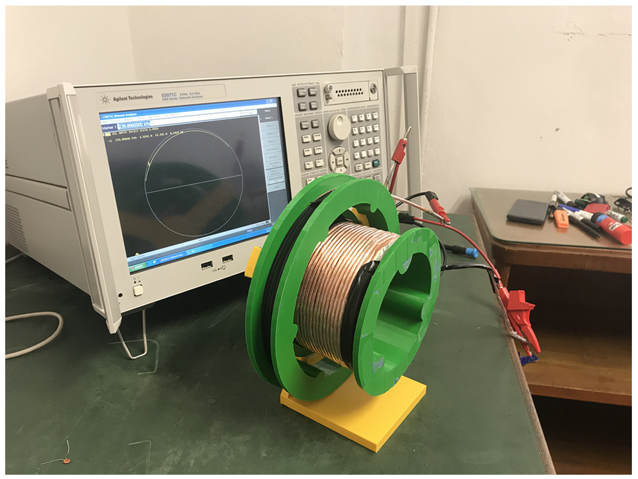
The WPT system has been implemented and a measurement campaign has been performed to verify the theoretical results; a photo of the whole system composed by the four coils (assembled in the form of two coil-loop subsystems), the filters and the VNA is shown in
Figure 8.
The theoretical results showing that the inner coils can be chosen as data access point in order to increase bandwidth are experimentally verified; in particular we realized two test cases for two different distances, namely 5 cm and 15 cm. The corresponding resonant frequencies and capacitors values are shown in
Table 4.
For each case, the series and parallel filters (
and
) have been realized as ideal second order series or parallel
circuits; from the theoretical calculations (with the analytical expressions presented in the
Appendix A), we have verified that the proper selection of the data access point is strictly influenced by the filter design; in particular, considering that all the filters must resonate at the chosen frequency
, there is a degree of freedom in the choice of the inductor or the capacitor. In order to highlight the different behavior, the authors report here two different choices for each case study:
- (a)
The filter is constructed with L and C components whose values are coincident to the values of L and C of the inductor it is connected to. For instance, the filter connected to the drive loop 1 having inductance equal to and capacitance is realized with components and ; the same holds for the series filter .
- (b)
The filter is constructed with L and C components whose values are coincident the values of L and C of the inductor they are not connected to. For instance, the filter connected to the drive loop 1 is realized with components and ; the same holds for the series filter .
As it will be shown later, these two choices lead to different behavior of the data channel. It must be pointed out that the simulation results shown in this section have been obtained using for
,
,
and
the measured values (and not the design values) given in
Section 3.
5.2. Case Study 1 (Distance 5 cm)
For Case Study 1, the following table resumes the filter parameters for the subcases (a) and (b); in all the figures reported in this section, the transfer function has been taken as output; when the power channel is considered, in order to obtain the scattering parameter
it is sufficient to multiply by 2 the transfer function
since the circuit works with the termination resistances of
of the VNA, according to
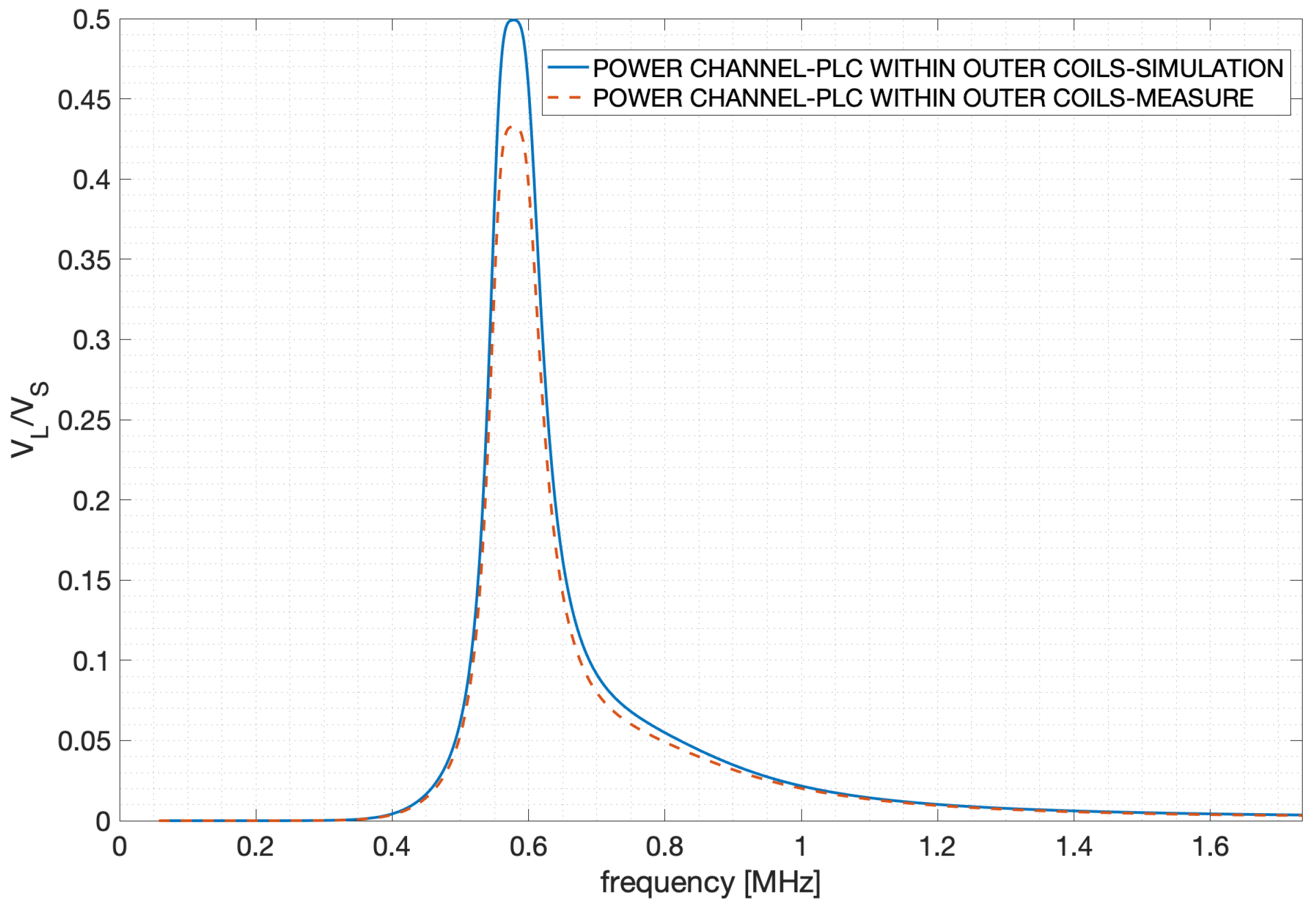
Figure 9 shows the comparison between the analytical calculations and measurements for the power channel in Case Study 1a; in particular
Figure 9 is referred to the data access from the outer coils (the system represented in
Figure 2), and the values of the filters as reported in
Table 5. While from the design results at the resonant frequency the power transfer should achieve an efficiency close to unity (where efficiency is referred to as power transfer efficiency and not frequency efficiency), measurements shows a decrease of about
: this is due to the components’ tolerance and parasitic effects. For instance, the parallel
filter does not behave exactly as an ideal filter; however, the design frequency is reasonably achieved, together with a good maximum value of
.
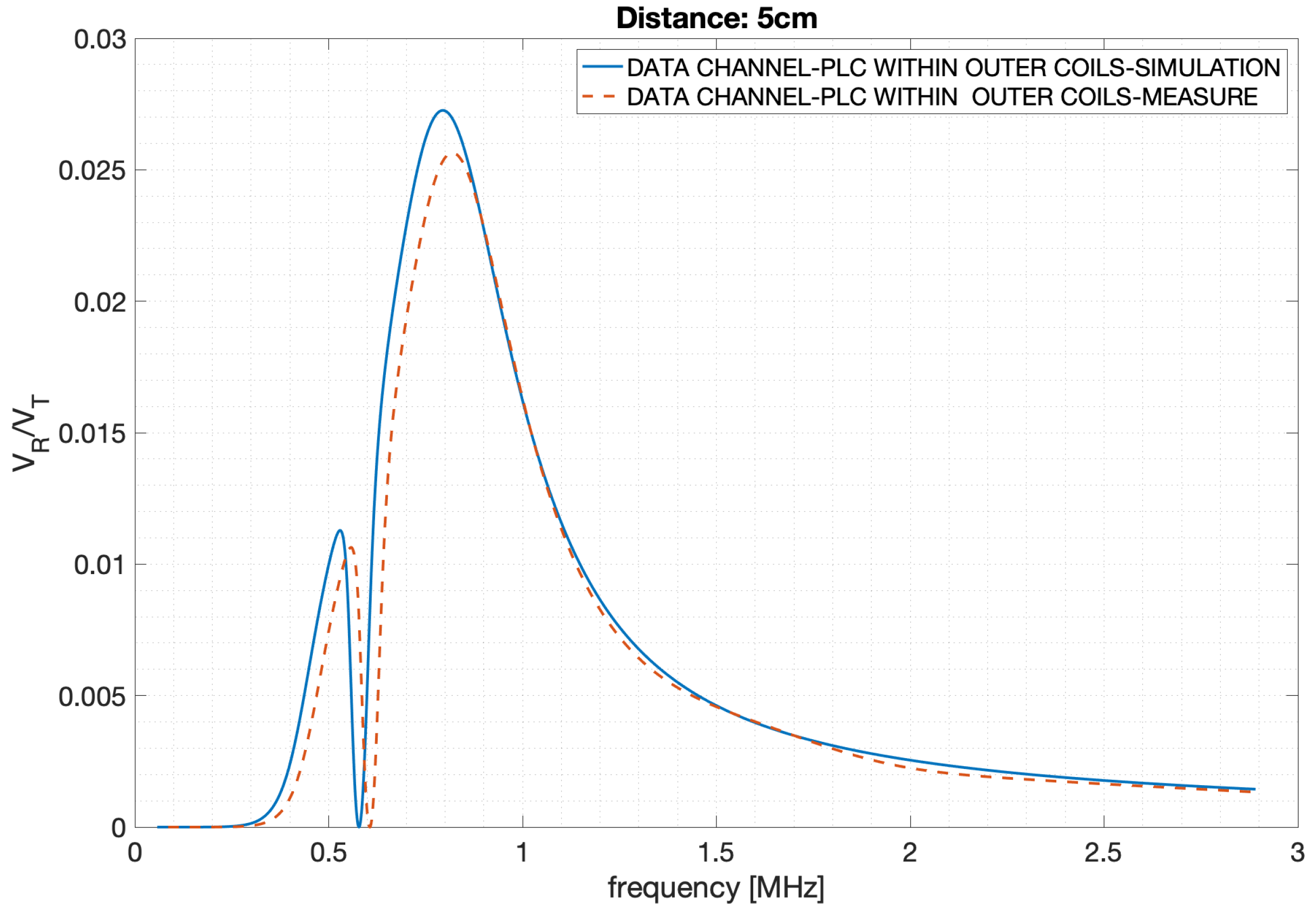
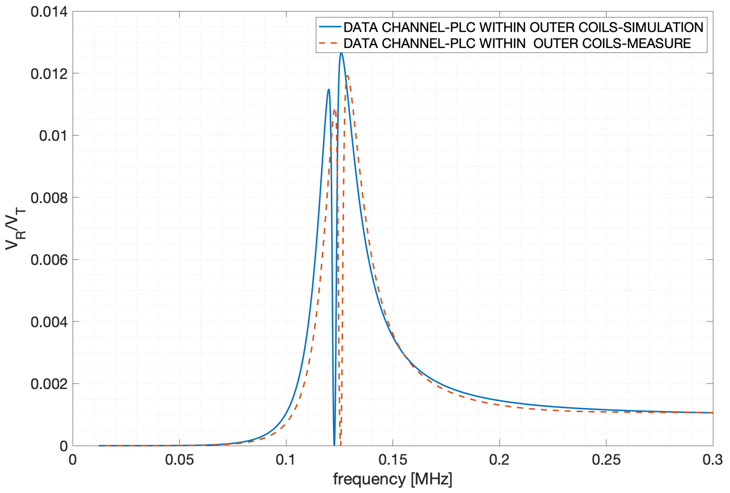
For the same circuit (data between outer coils), a comparison between analytical calculations and measurement have been performed, and shown in
Figure 10; in this case we notice again a peak reduction and a slight frequency shifting phenomenon. Both phenomena are due, also in this case, to the tolerances and non-ideality of the components. The selection of higher quality components and a sensitivity study (performed for instance with MonteCarlo analysis as in [
9]) could be useful for a more accurate realization of the system.
As shown in the previous figures, the designed system performs as desired; for this reason the following figures only show analytical results.
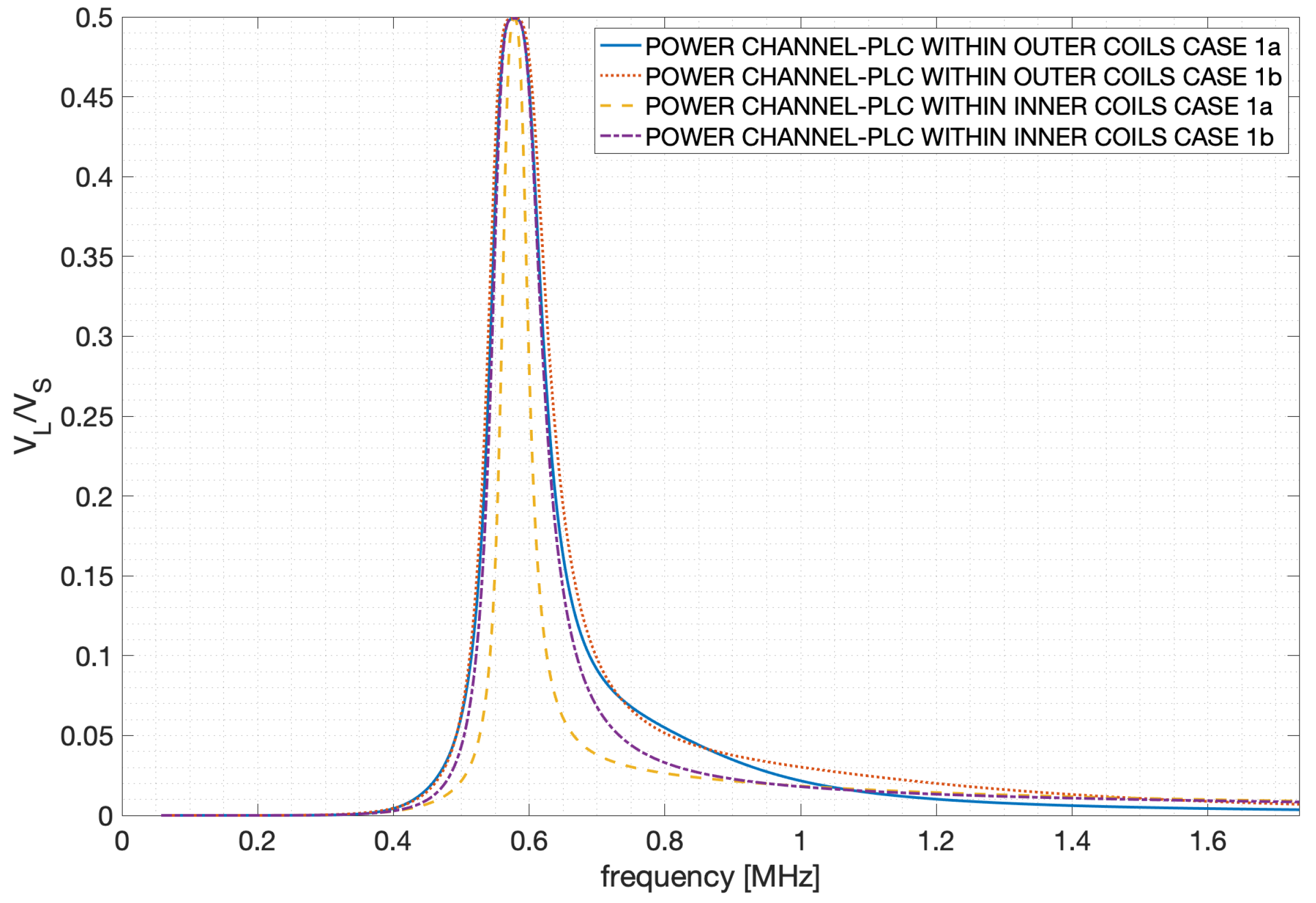
Figure 11 shows the analytical results relative to the power transfer function for the two circuits (data from inner and outer coils), each of them implemented with the different filters as reported in
Table 5, resulting in a total number of simulations equal to four. In particular,
Figure 11 shows that using the inner coils for data transfer leads to a slightly narrower power channel with respect to the use of outer coils; in addition, different implementation of the filters can enhance or reduce this behavior.
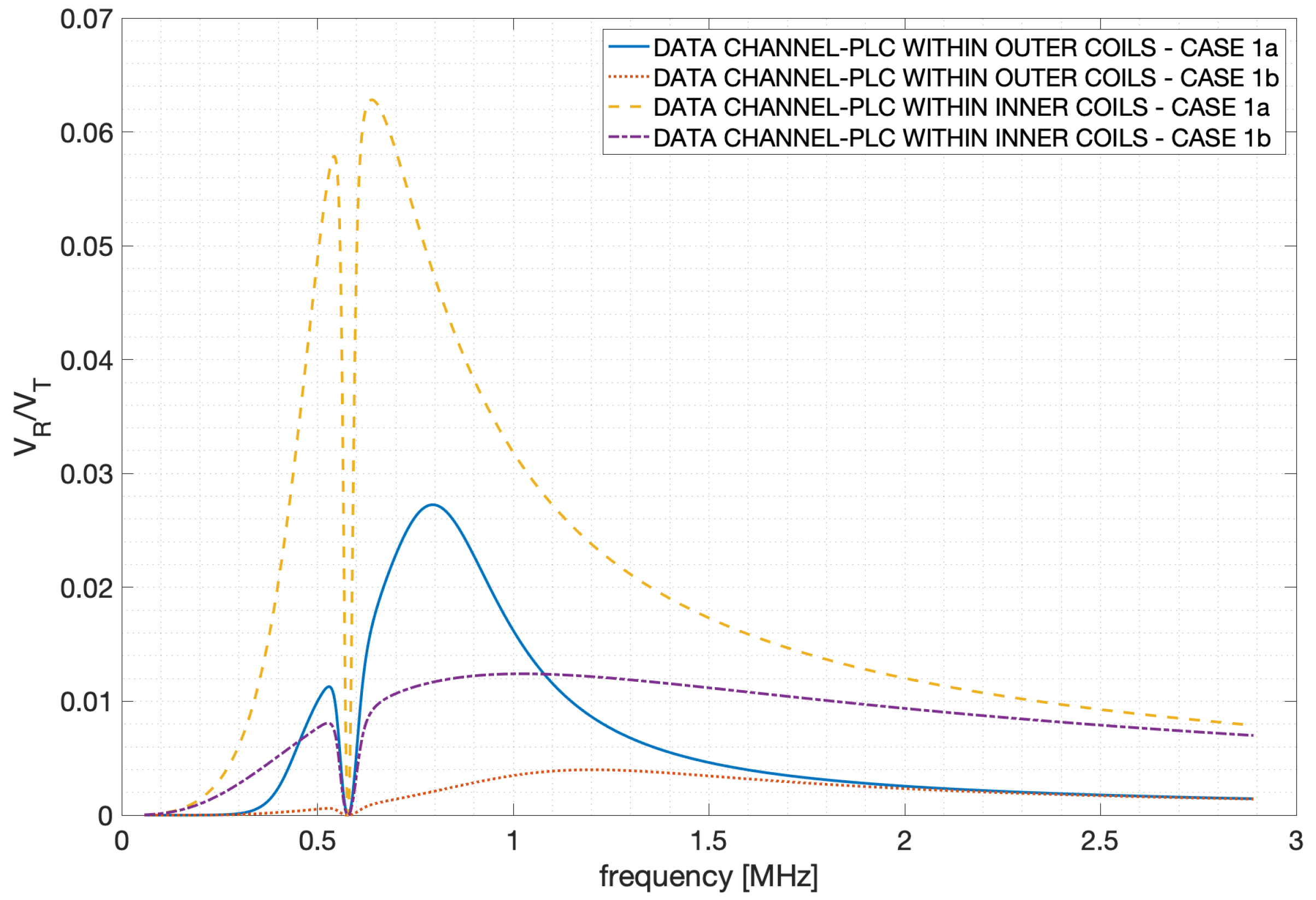
Figure 12 shows the analytical results relative to the data transfer function for the two circuits (data from inner and outer coils), each of them implemented with the different filters as reported in
Table 5. The different behaviors of the transfer functions relative to the data channel are now extremely evident and it is not only reduced to a slight difference in the bandwidth. In particular, there is a strong effect on the transfer function both of the different data access point and filter realization. In particular, the best performing solution in terms of bandwidth consists in the use of inner coils with the series filters implemented as
and
, while the worst solution consists in the use of outer coils with the parallel filters implemented as
and
.
This qualitative analysis is validated by the calculation of the channel capacity in the four previous cases. We can refer to the Shannon-Hartley approach: the signal sent from the transmitter is filtered by the channel transfer’s function, which is in general selective and reaches the receiver together with the noise which, in this case, is mainly produced by the signal generator and RF amplifier. The following Shannon-Hartley law can be used:
in which
C is the channel capacity in bits per second,
B is the bandwidth of the channel,
is the signal power spectrum,
is the noise power spectrum and
f is the frequency. As for the channel capacity objective, the following assumptions are made: both the injected power spectrum
, and the noise power spectrum
, are frequency independent, and the noise is considered as additive white Gaussian noise at the receiver. The
is then defined as
, and the received power spectrum can be expressed as a function of the injected power spectrum and the transfer function, according to
. Under these assumptions, (
8) can be rewritten as
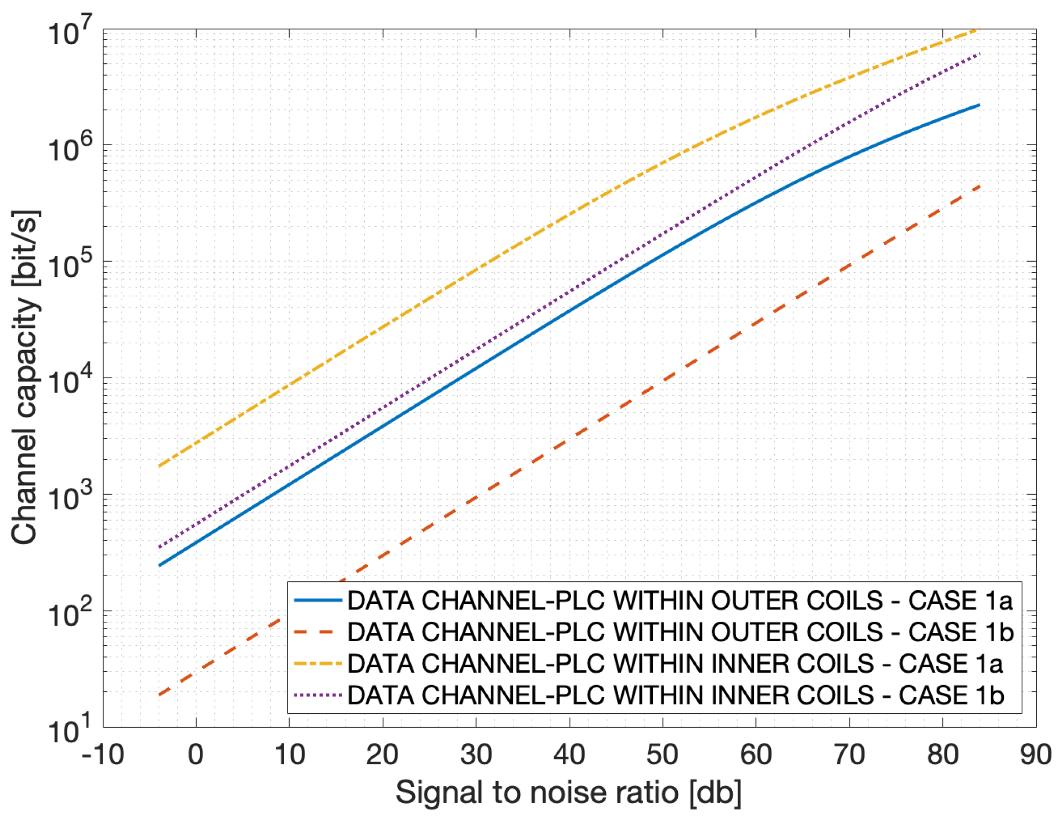
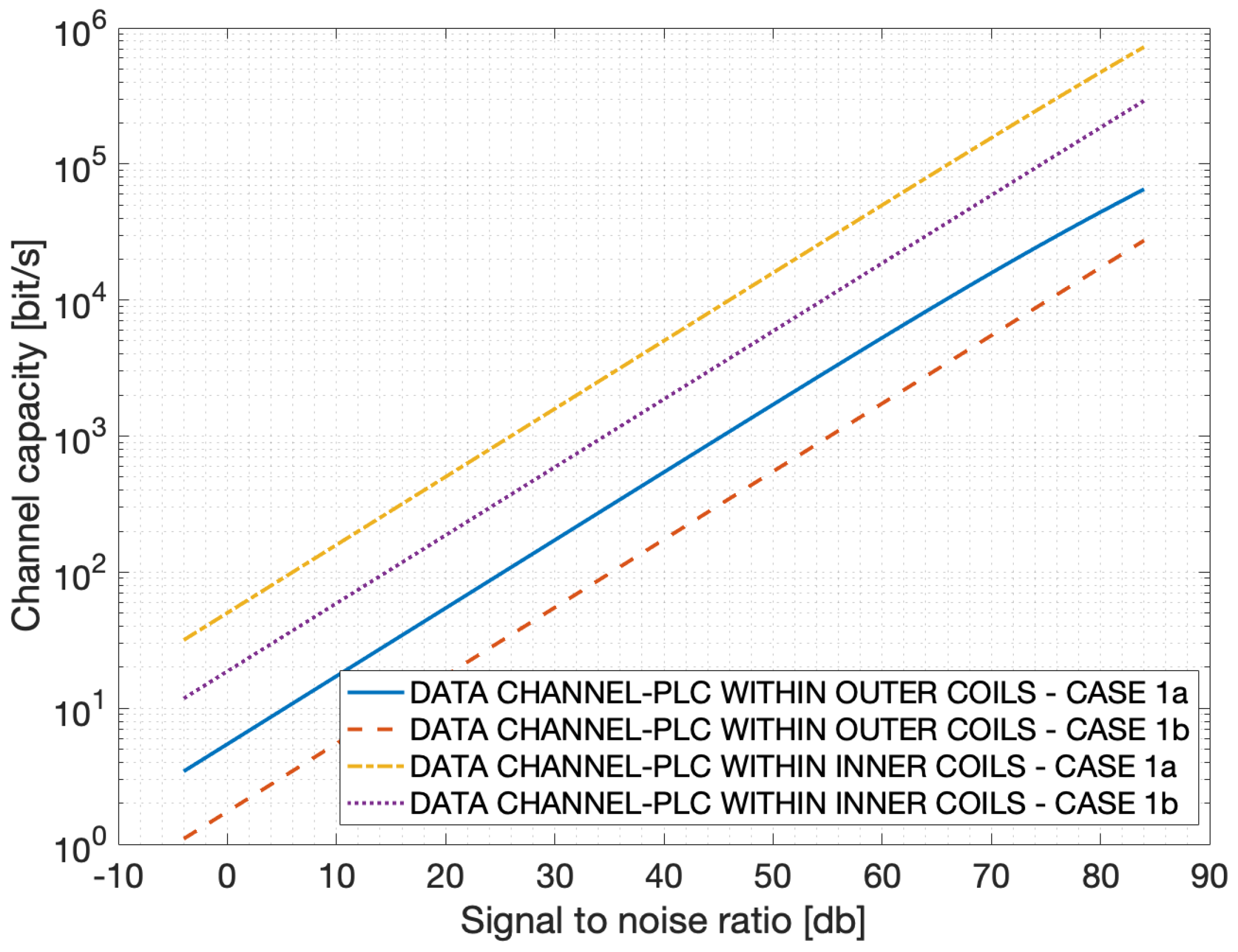
Figure 13 shows the channel capacity in the frequency band
, typical of broadband power line. It is evident that reasonable data transmission capacity can be obtained for a 5 cm distance, and that for high signal to noise ratio a speed of above 1Mbit per second can be reached. In addition, as qualitatively seen from the transfer functions, the data communication between inner coils is outperforming other practical solutions.
5.3. Case Study 2 (15 cm Distance)
For the Case Study 2 (15 cm distance), the following table resumes the filter parameters for the subcases (a) and (b) (as a matter of fact, the filters are the same used for Case Study 1).
For the sake of conciseness, relative to Case Study 2, we show the comparison between analytical results and simulation only for the data transfer between outer coils, as reported in
Figure 14. In this case we notice again a peak reduction and a slight frequency shifting phenomenon due to components characteristics.
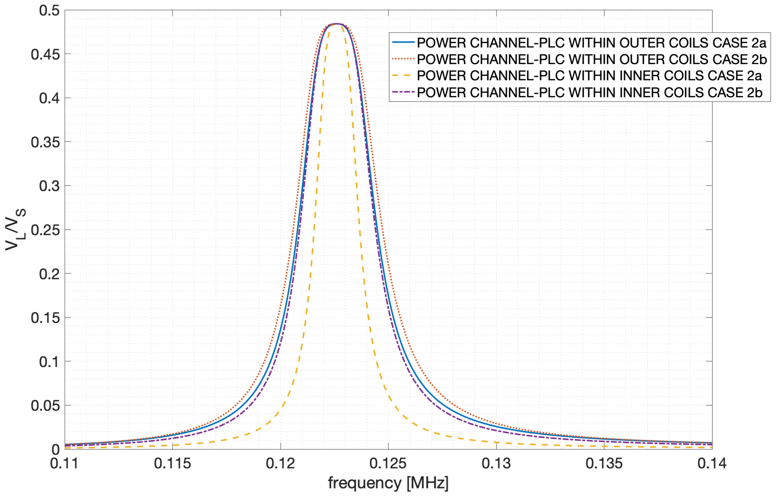
Figure 15 shows the analytical results relative to the power transfer function for the two circuits (data from inner and outer coils), each of them implemented with the different filters as reported in
Table 6. As happened for Case Study 1, it can be noticed that the use of the inner coils for data transfer leads to a slightly narrower band of the power channel with respect to the use of outer coils. In addition, a reduction of the peak value (transfer efficiency) is observed, and it is due to the increased distance: only in the case of an ideal system without parasitic resistances can maximum transfer (
) be achieved; in realistic cases at increasing distances there will always be a decreasing efficiency.
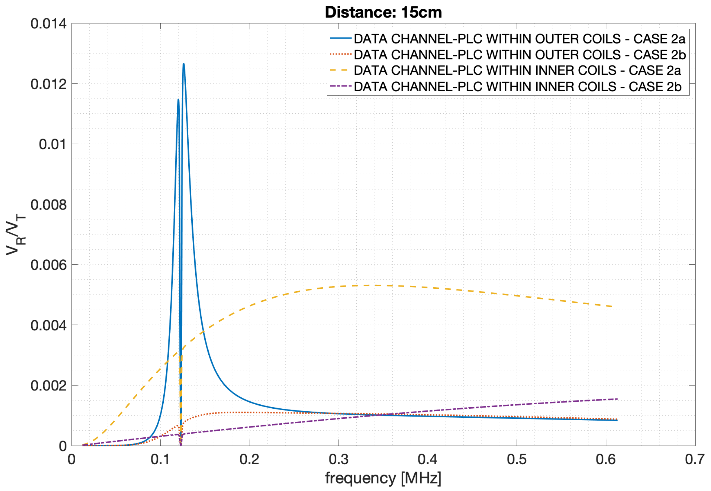
Figure 16 shows the analytical results relative to the data transfer function for the two circuits (data from inner and outer coils), each of them implemented with the different filters as reported in
Table 6. Looking at the graphs from a qualitative point of view, the two best performing solutions (in terms of bandwidth) seem to be the ones in which data is transferred either between inner or outer coils with the filters (either parallel or series) implemented as in case 2a (i.e., with the filters elements
L and
C having the same values as the coils’inductance and resonance capacitors). However data with outer coils with filters a) have a narrow bandwidth centred on the notch, giving selectivity that is not suitable for data transmission.
Figure 17 shows the channel capacity for Case Study 2. This case study, characterized by a higher distance, shows a lower data transmission capacity if compared to Case Study 1, however the system performances could be more than acceptable depending on the specific application. Also in this case the data transfer between inner coils is outperforming other practical solutions.
5.4. Discussion
The measurements and calculations shown before can be used to draw the following considerations relative to the combined system allowing both power and data transfer wirelessly and guaranteeing an efficient interface with a PLC system.
- (a)
If the power section is properly designed in order to guarantee the desired power at the receiver (i.e., maximum power, maximum energy efficiency or an intermediate situation), the presence of additional filters for data transfer does not affect power at the resonant frequency.
- (b)
The convenience of using different access points for data and power (data from inner coils) is influenced by the realization of the filters. From our analysis, data access from inner coils is convenient in terms of data bandwidth, provided that the proper series filter on the inner coils is designed.
- (c)
From our analysis, higher data bandwidth from inner coils (the most convenient approach) results in an increased selectivity of the power channel.
- (d)
It is known that PLC works well with attenuations that can reach up to −40 db, that corresponds to a voltage gain of . As for the injected power of typical PLC systems, the usual SNR is in the order of 60 db, leading to the more than acceptable capacities shown in the graphs.
Point (a) is valid if the filters’ components are selected with a high accuracy, something that will also prevent frequency shifting that reduces the system’s efficiency, especially thinking about point (c). The consideration of point (b) is valid based on the results obtained using basic filters. The particular choice of the values the L and C filters components has been performed for the sake of simplicity. In basic second order filters, the same resonant frequency can be obtained (theoretically) with an infinite combination of components, and when power is transmitted additional constraints on the components obviously arise. Furthermore, components dimension should also be taken into account in the design process, for instance speaking about higher value inductances.
Higher order filters will be the object of future investigations, since their use should be able to increase the system’s performance, especially from the data transfer point of view. The series and parallel filters discussed in the paper perform the operation that PLC couplers perform in commercial modems, i.e., impedance matching to achieve efficient data transfer and prevent power to damage the modem itself.
Higher order filters are generally used in PLC modems and can be properly designed for this specific system; a sentence regarding higher order filters is already present in
Section 5, but it has now been extended.
As a final consideration, the use of different access points for data and power can be of interest when a higher data bandwidth must be achieved, and when galvanic insulation between the power system and data modem is needed. In these cases, the cost of specific filters should be evaluated in order to obtain the desired performances.


