Nonlinear Model Establishment and Experimental Verification of a Pneumatic Rotary Actuator Position Servo System


Abstract
1. Introduction
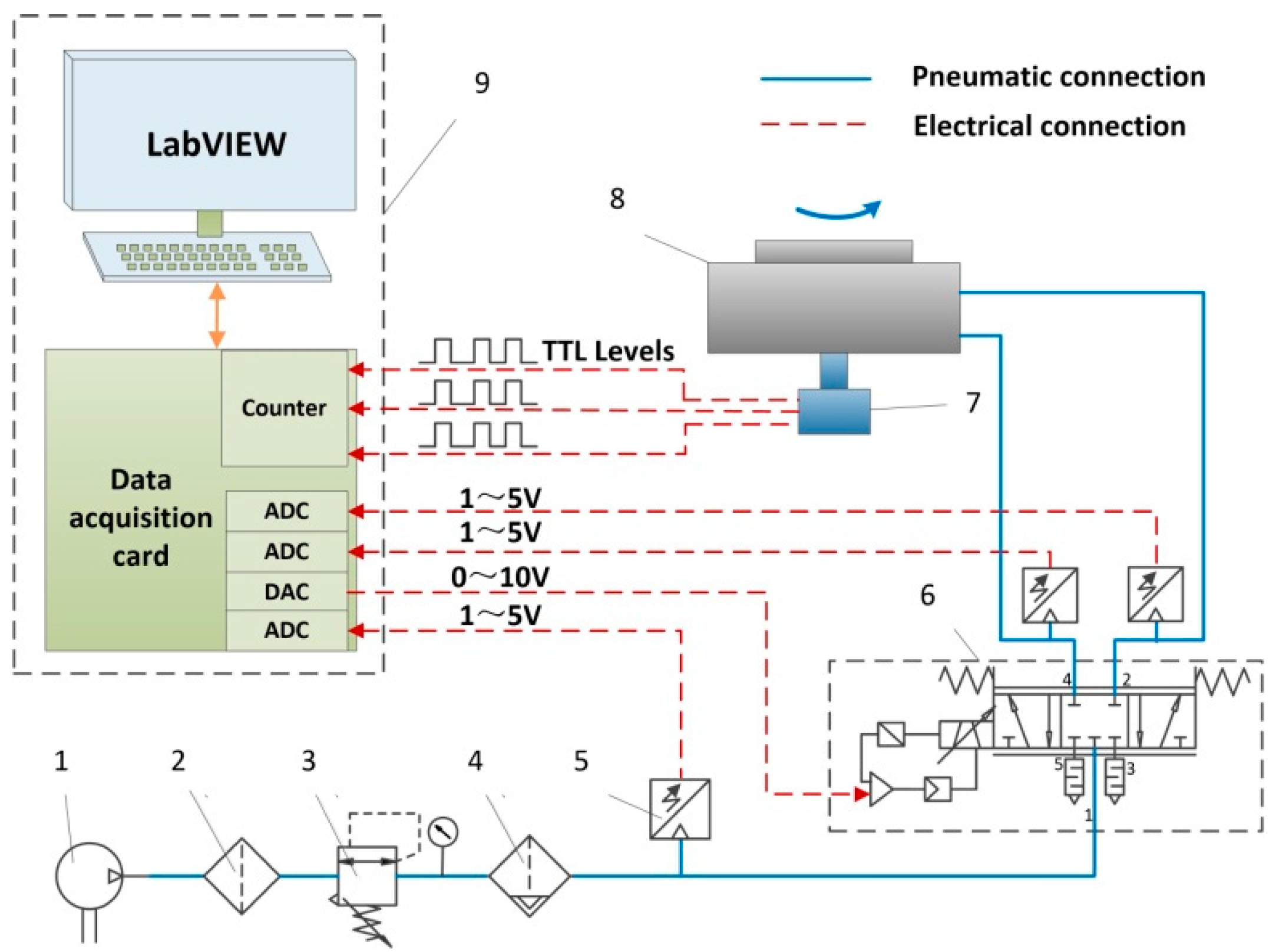
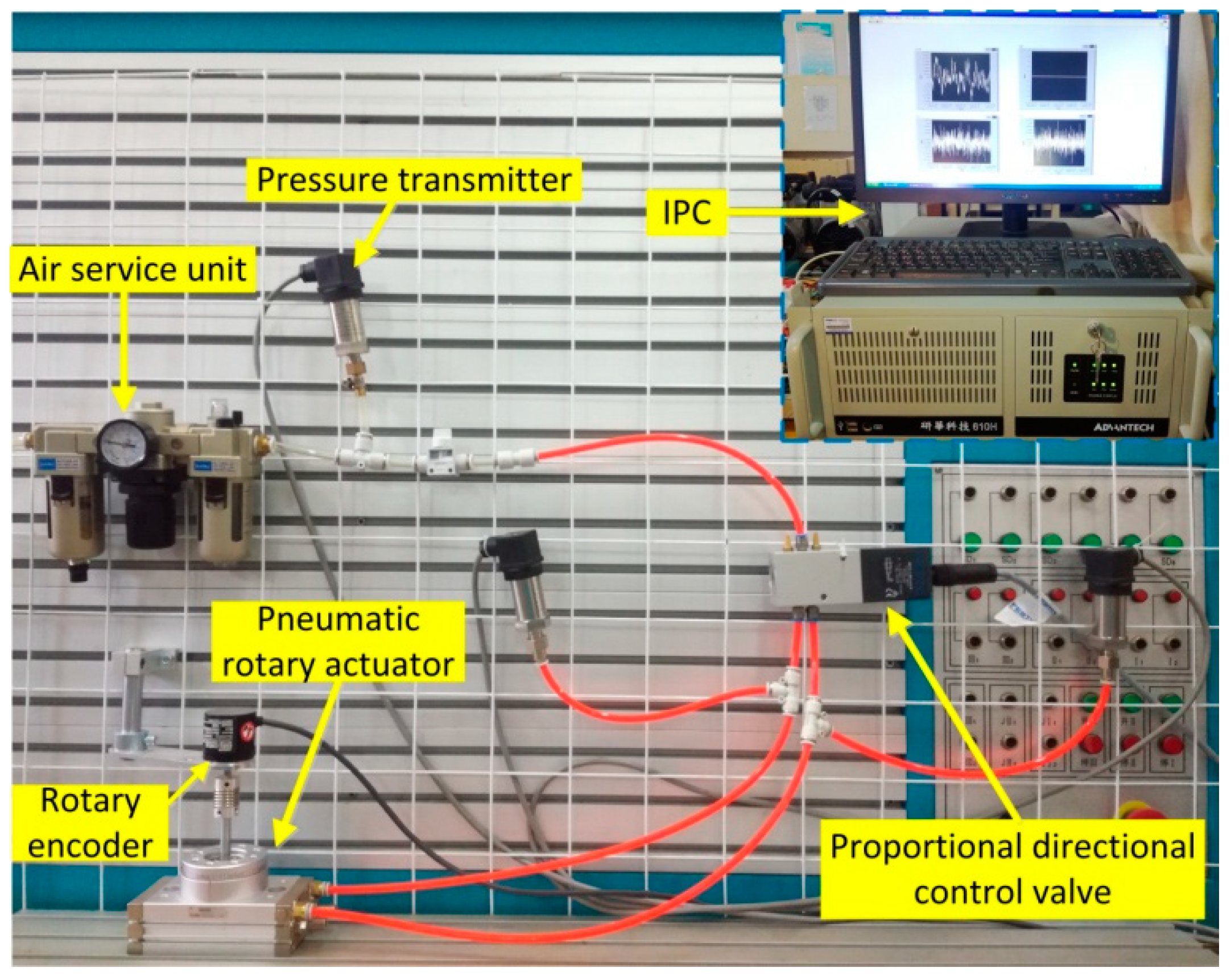
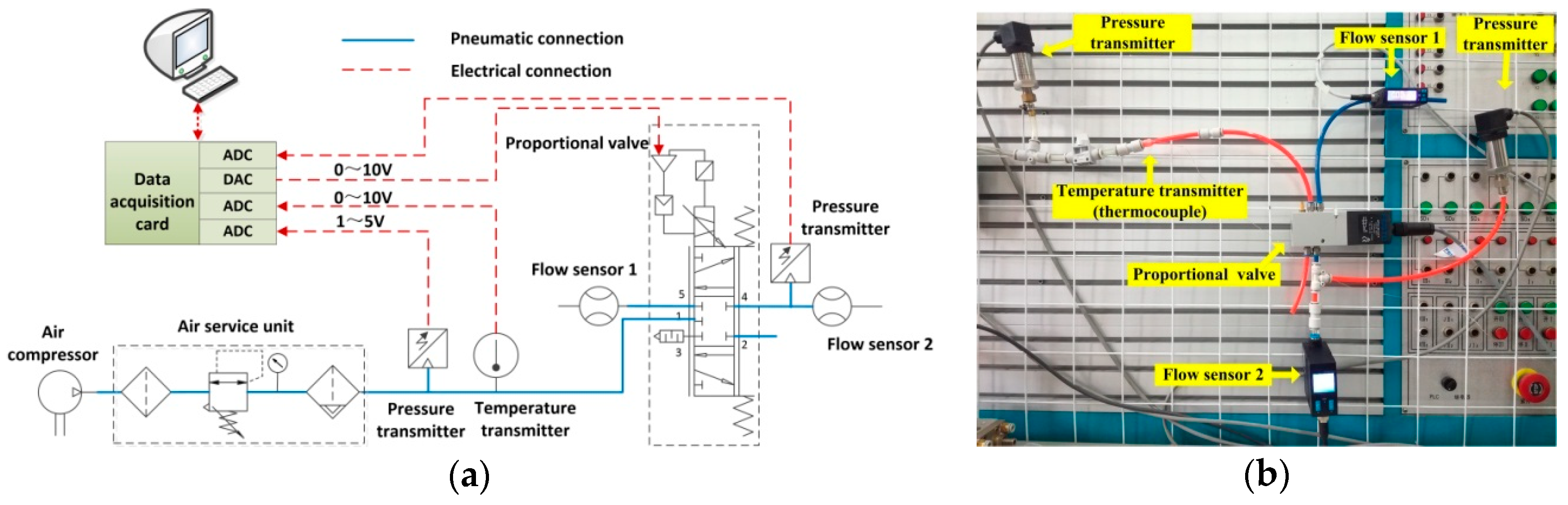
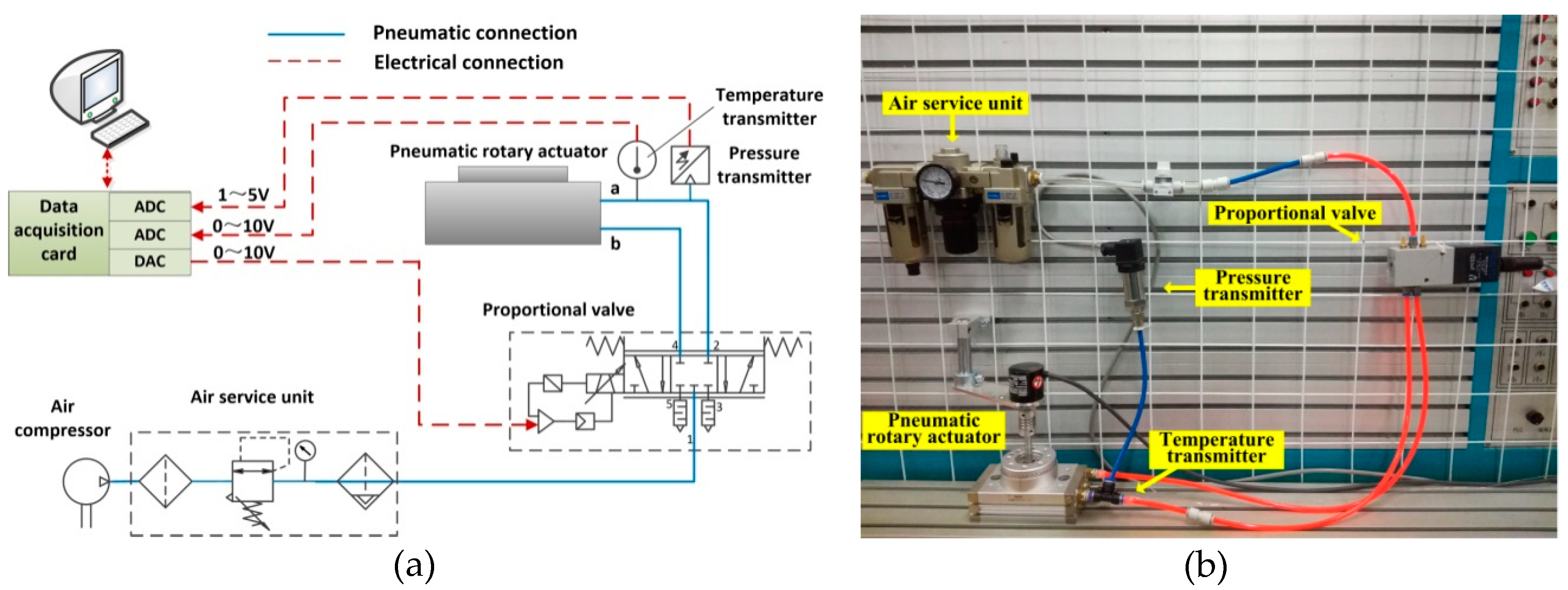
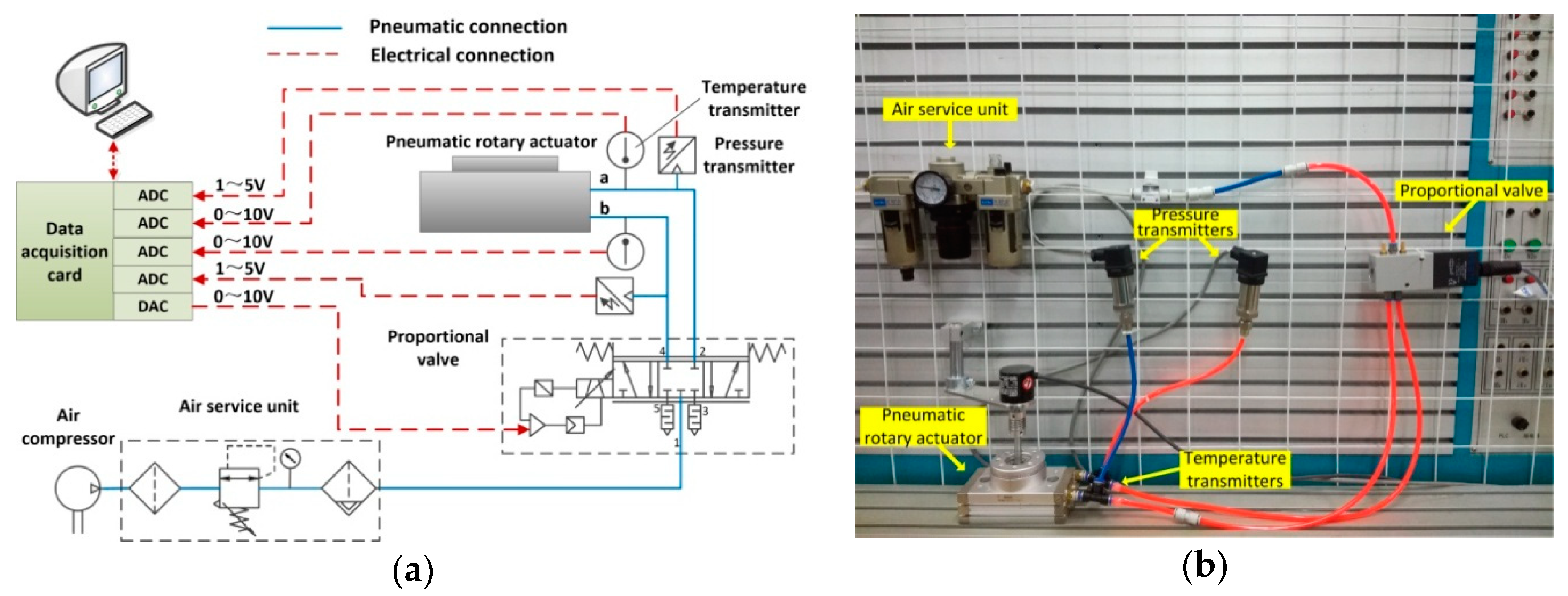
2. Experimental Set-Up
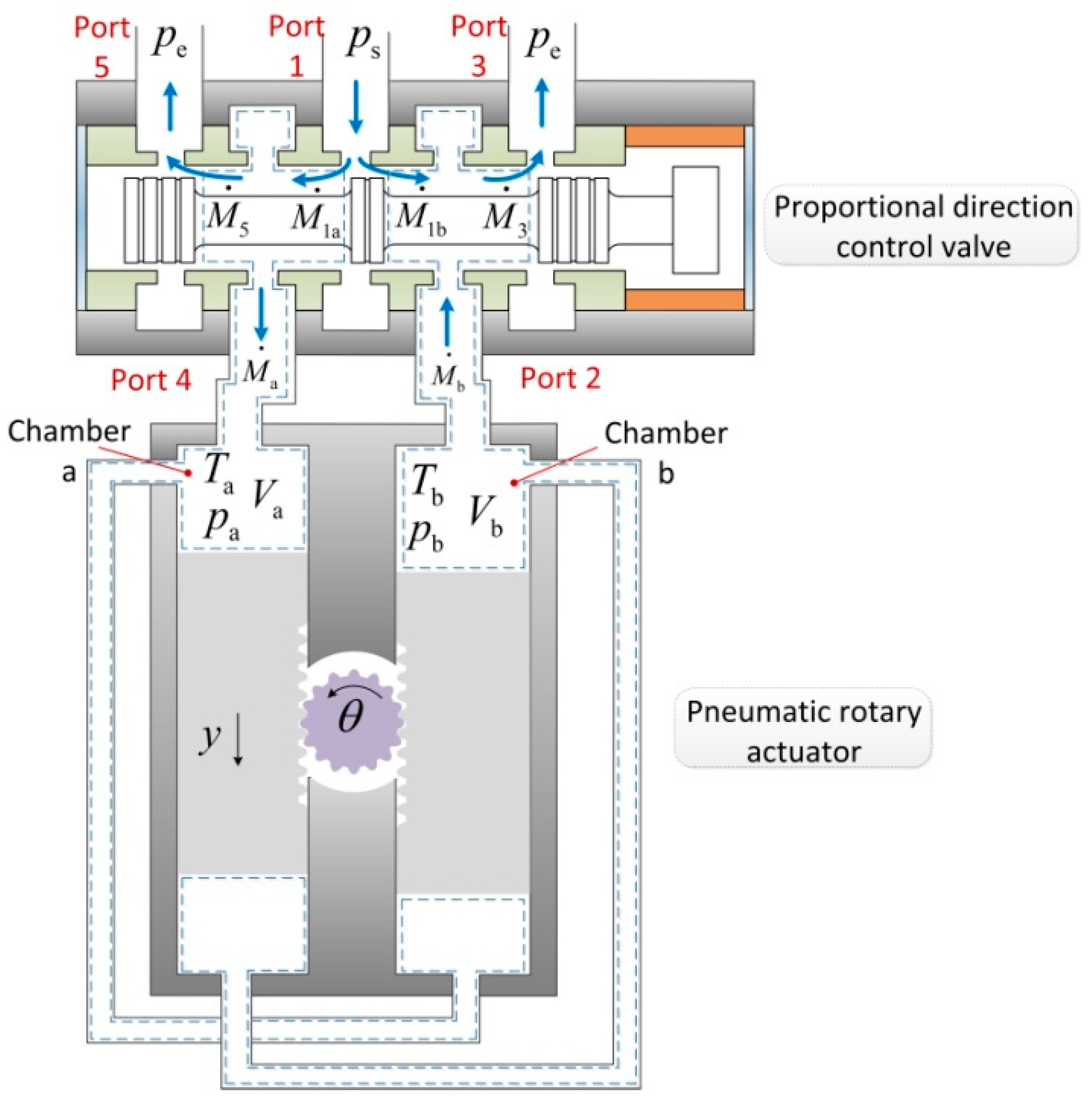
3. Mass Flow Rates of the Proportional Direction Control Valve
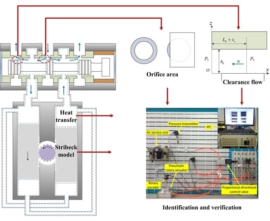
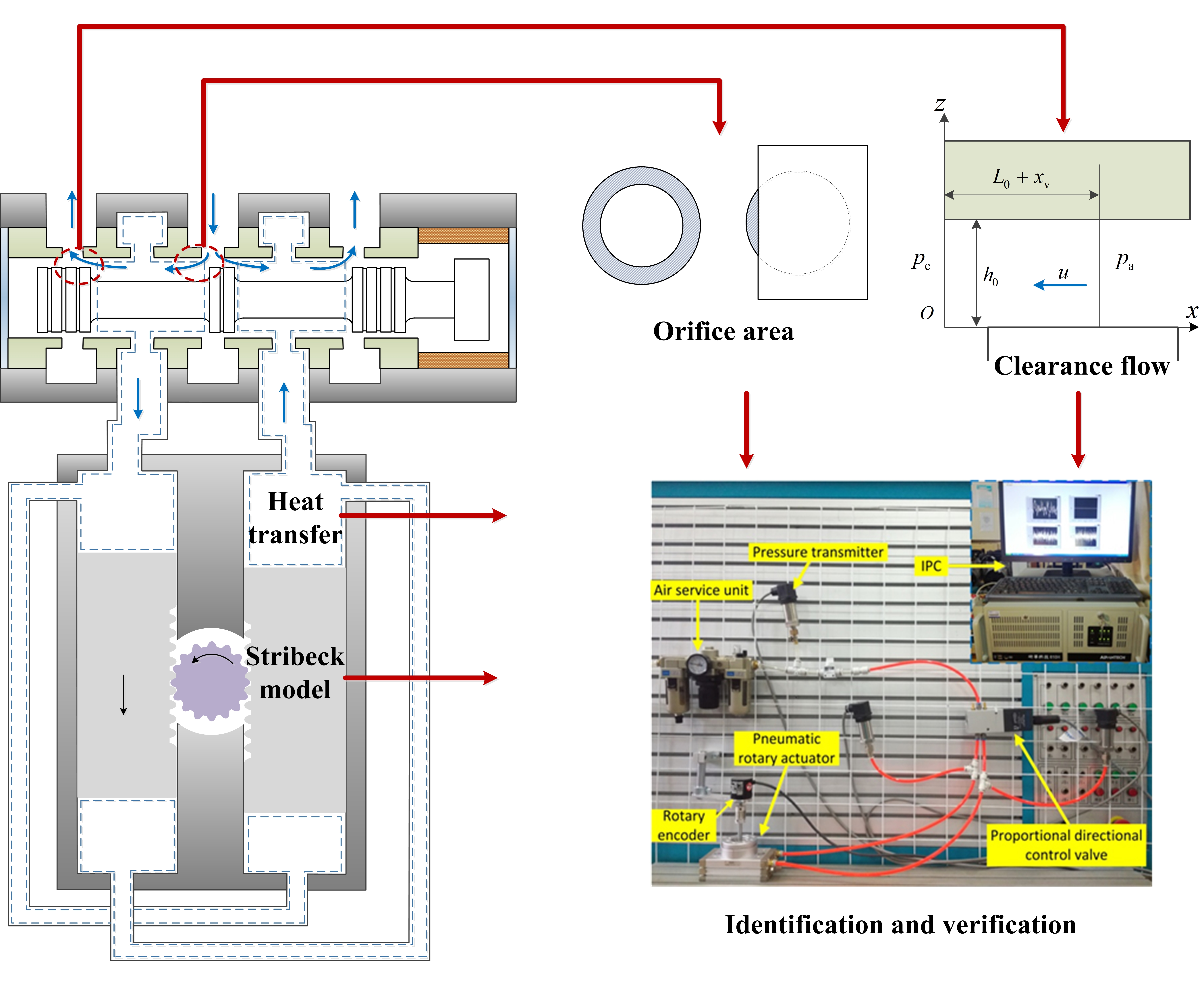
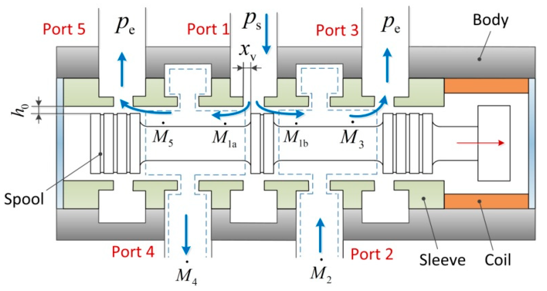
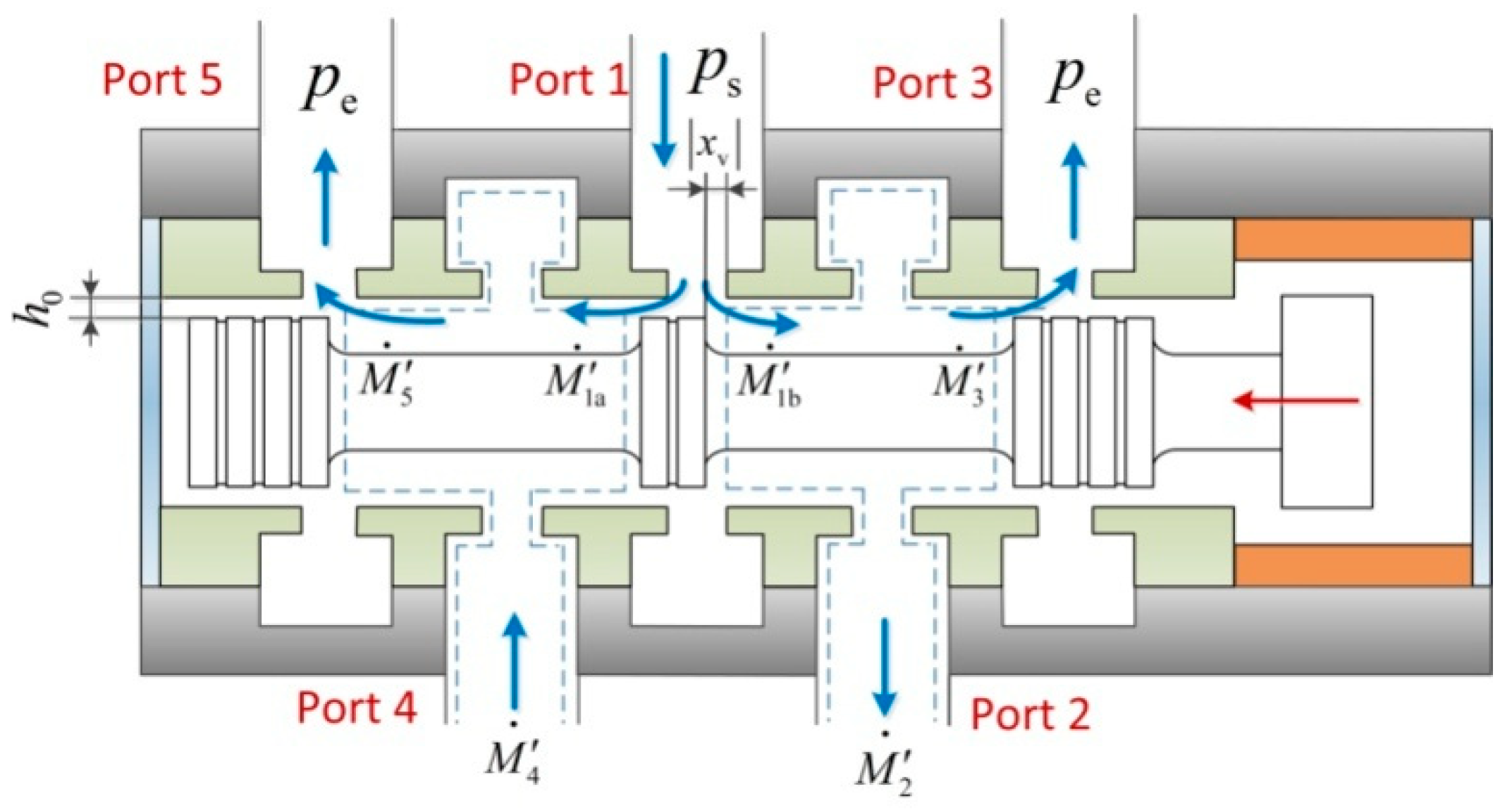
3.1. Gas Flow Mechanism in the Proportional Direction Control Valve
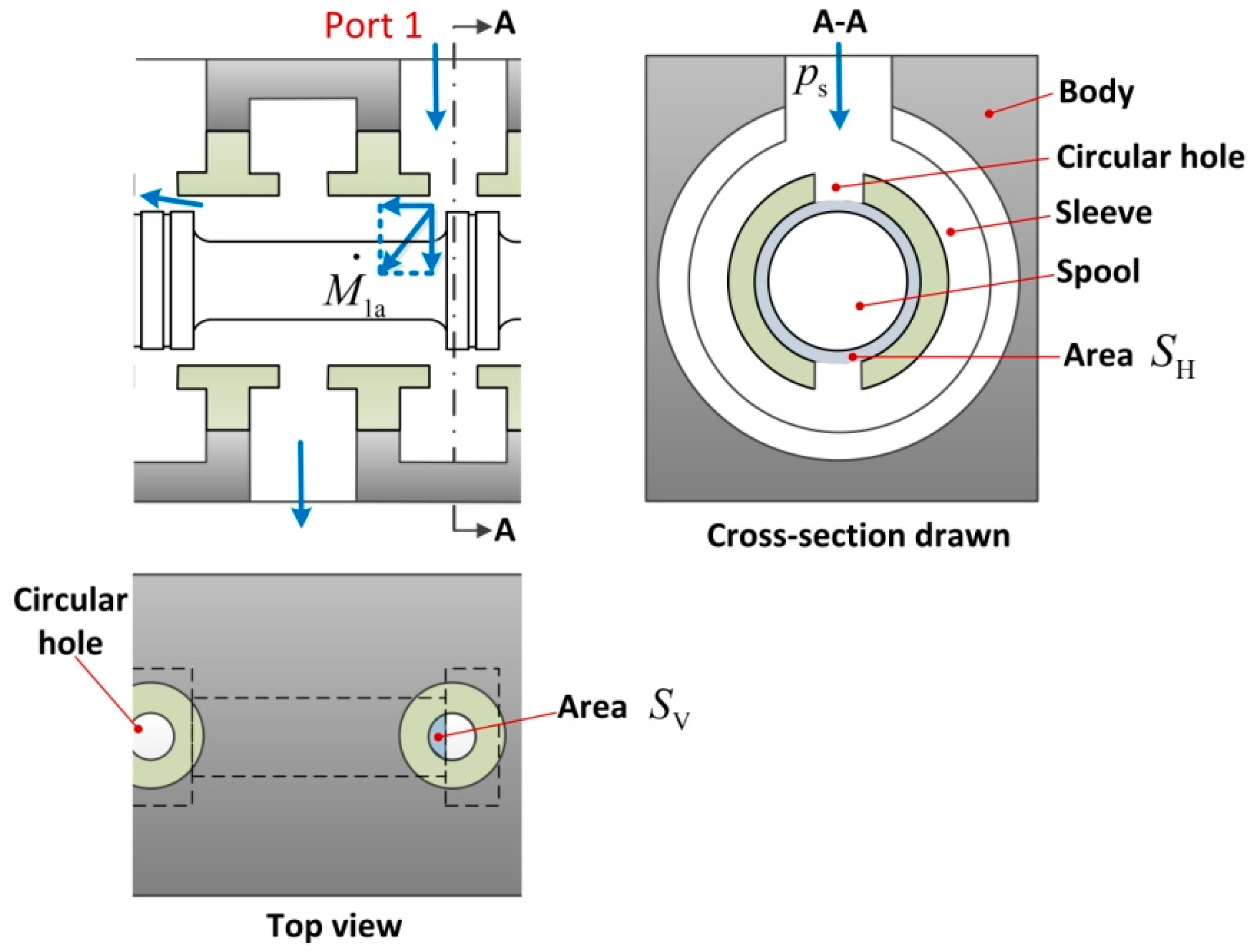
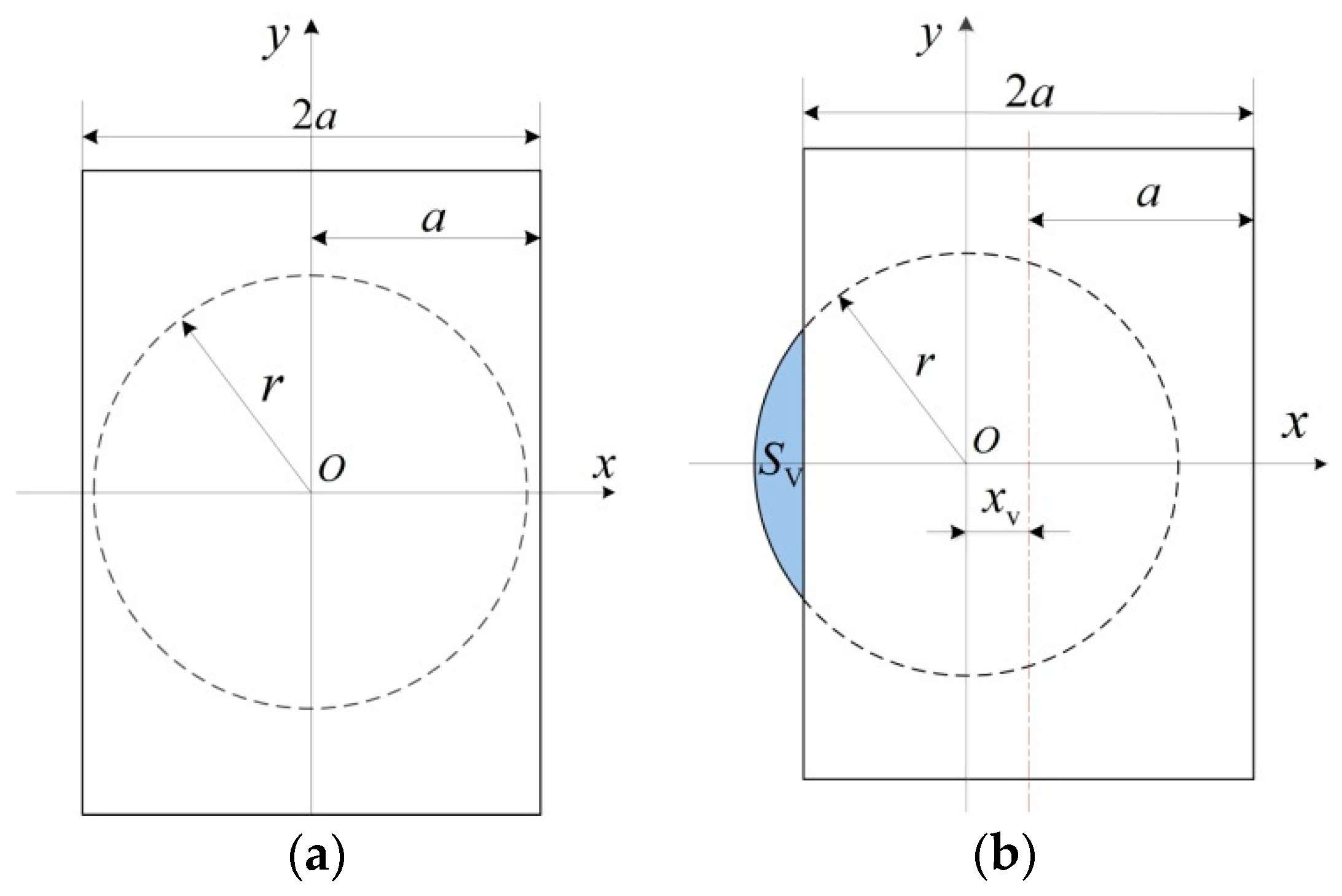
3.2. Mass Flow Rates of the Gas Flowing through the Orifices
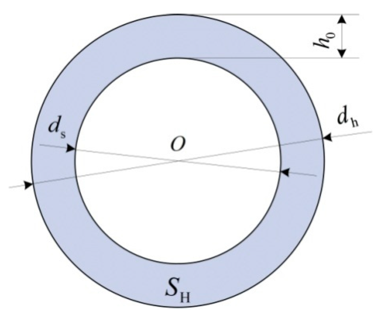
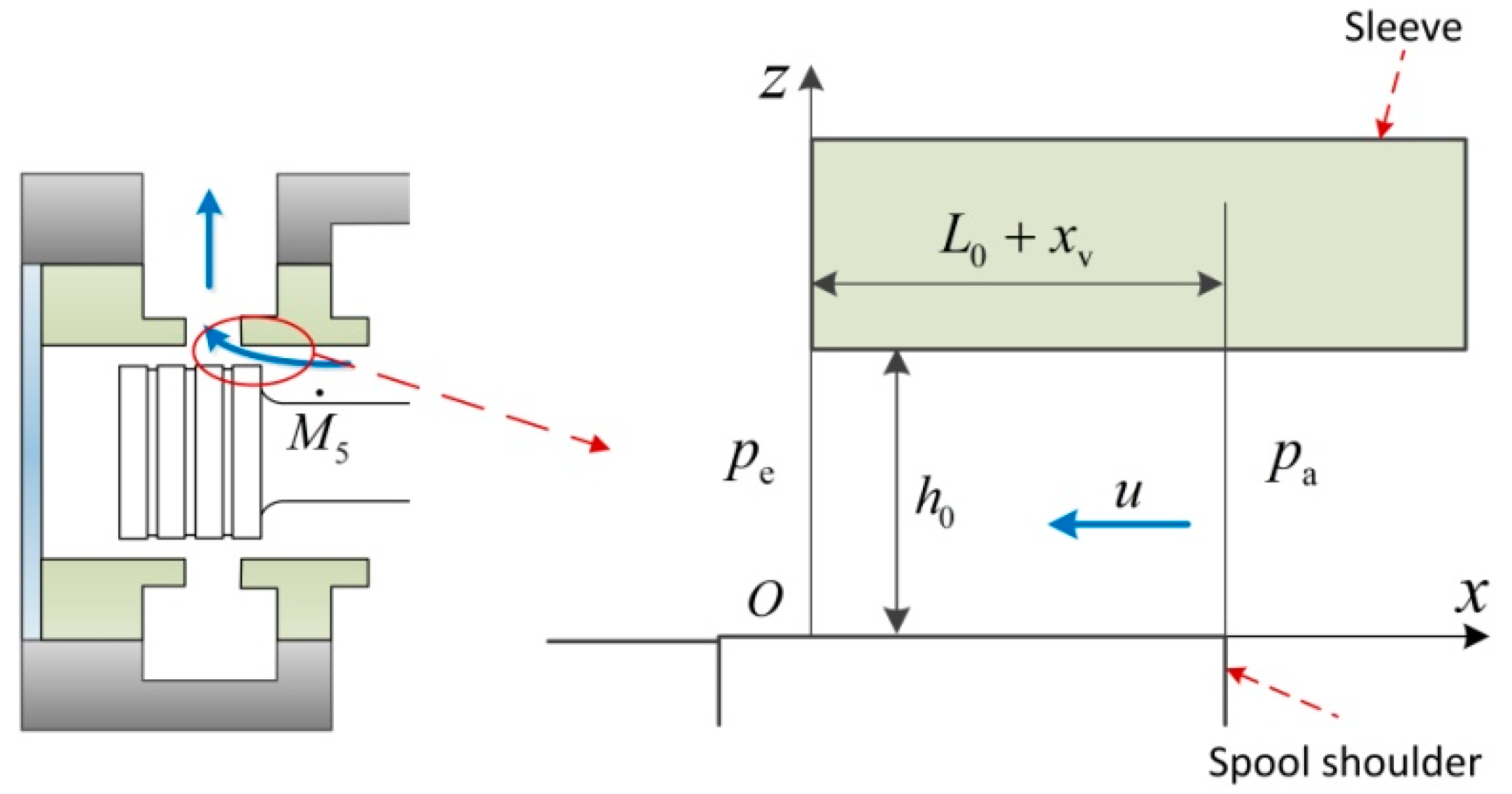
3.3. Mass Flow Rates of the Gas Flowing through the Clearances
3.4. Mass Flow Rates When the Spool Moves Backward
4. Non-linear Model of the Valve-Controlled Actuator System
4.1. Energy Equation
4.2. Pressure Differential Equation
4.3. Dynamic Model
5. Identification of Model Parameters
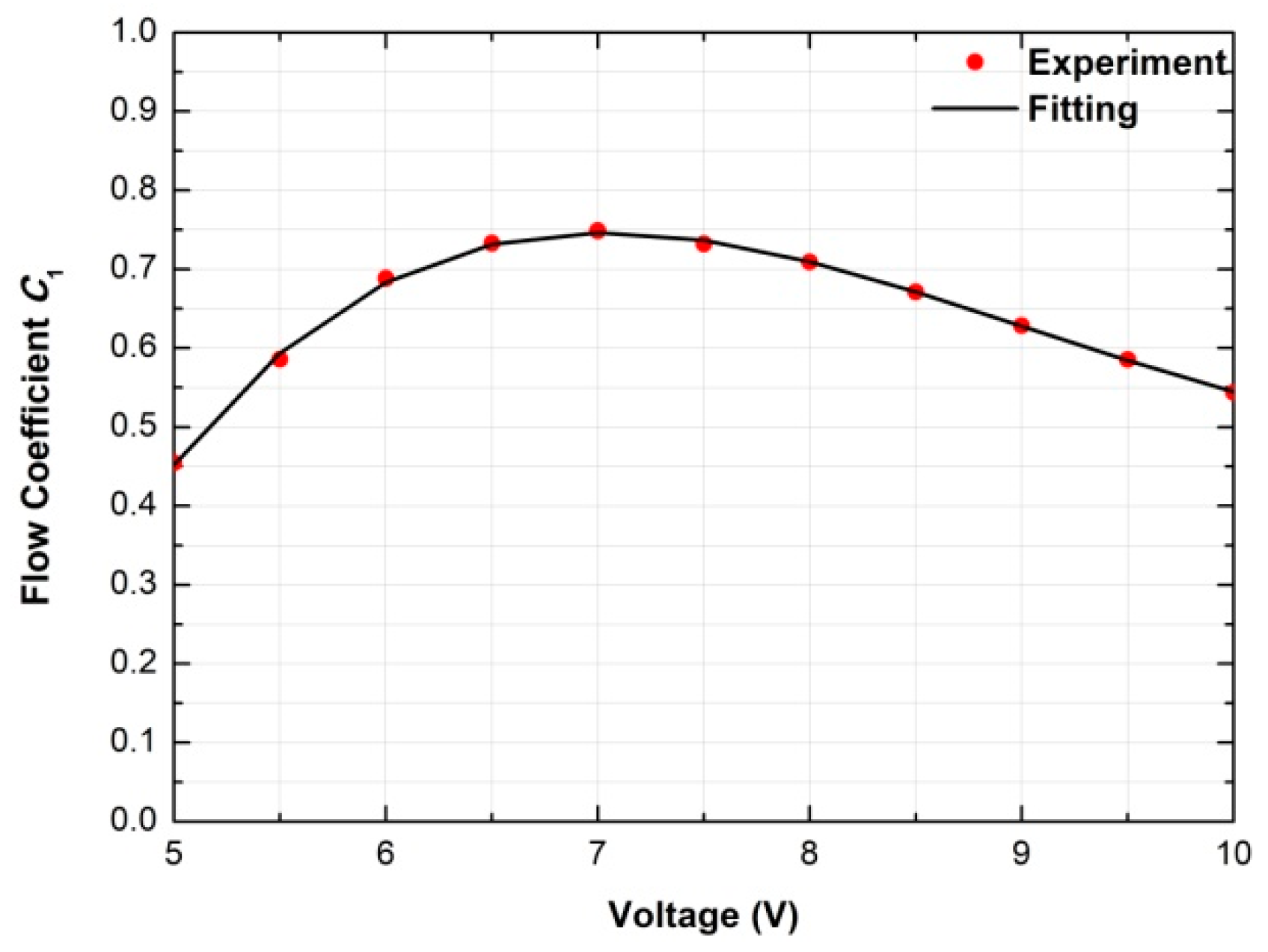
5.1. Flow Coefficient
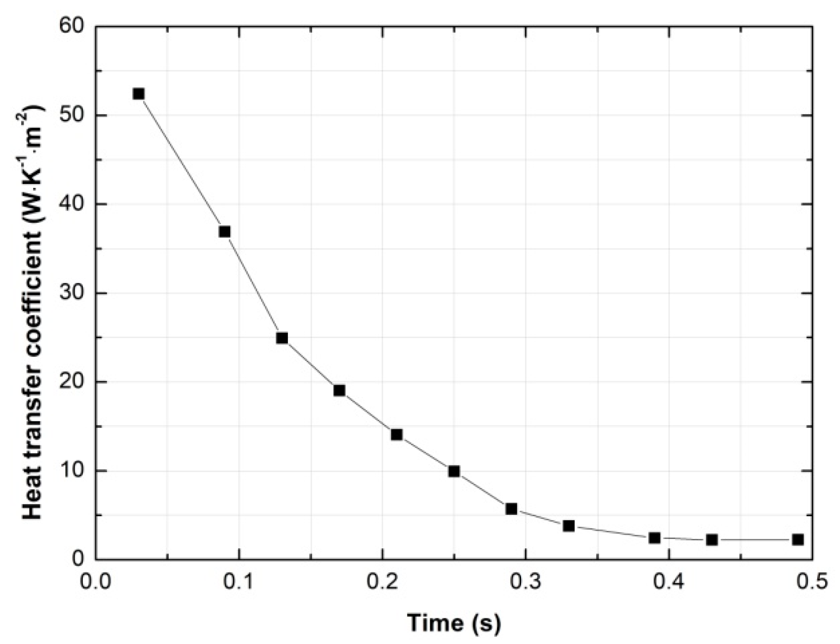
5.2. Heat Transfer Coefficient
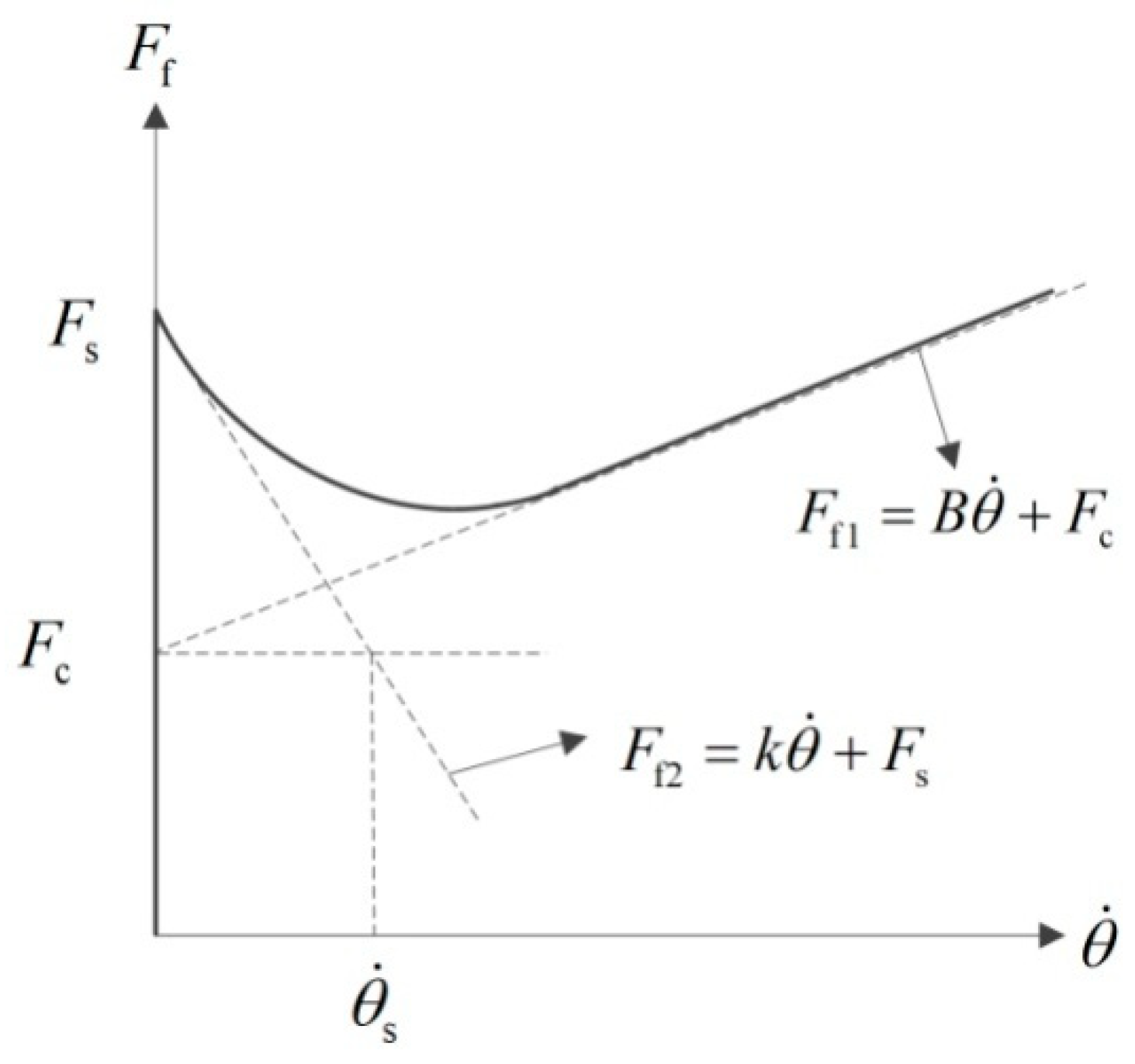
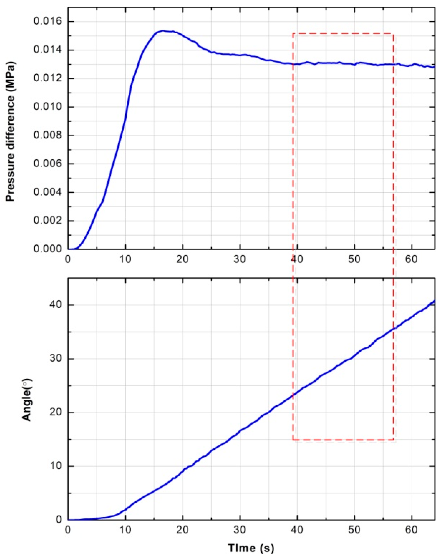
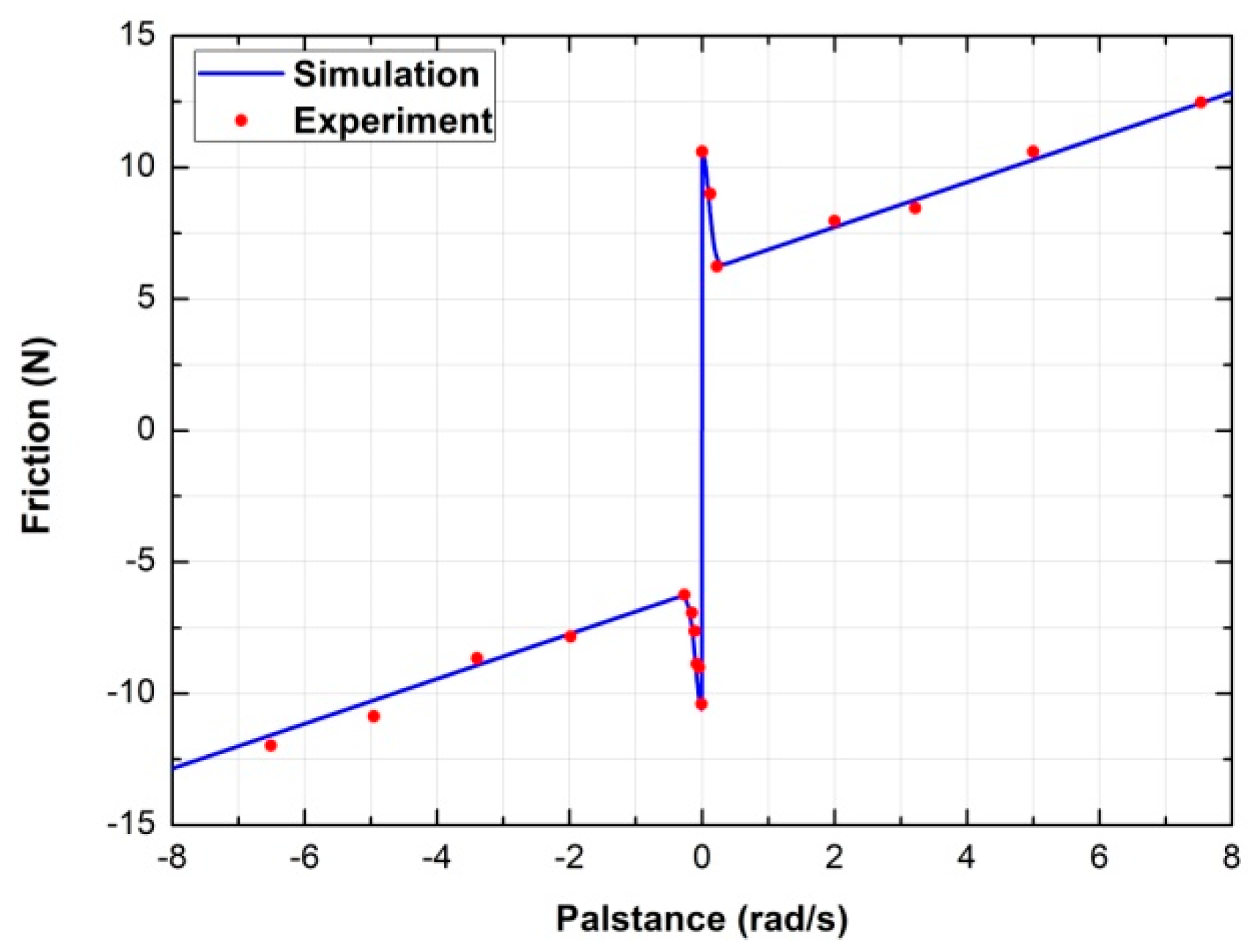
5.3. Friction Parameters
6. Verification of the Non-Linear Model
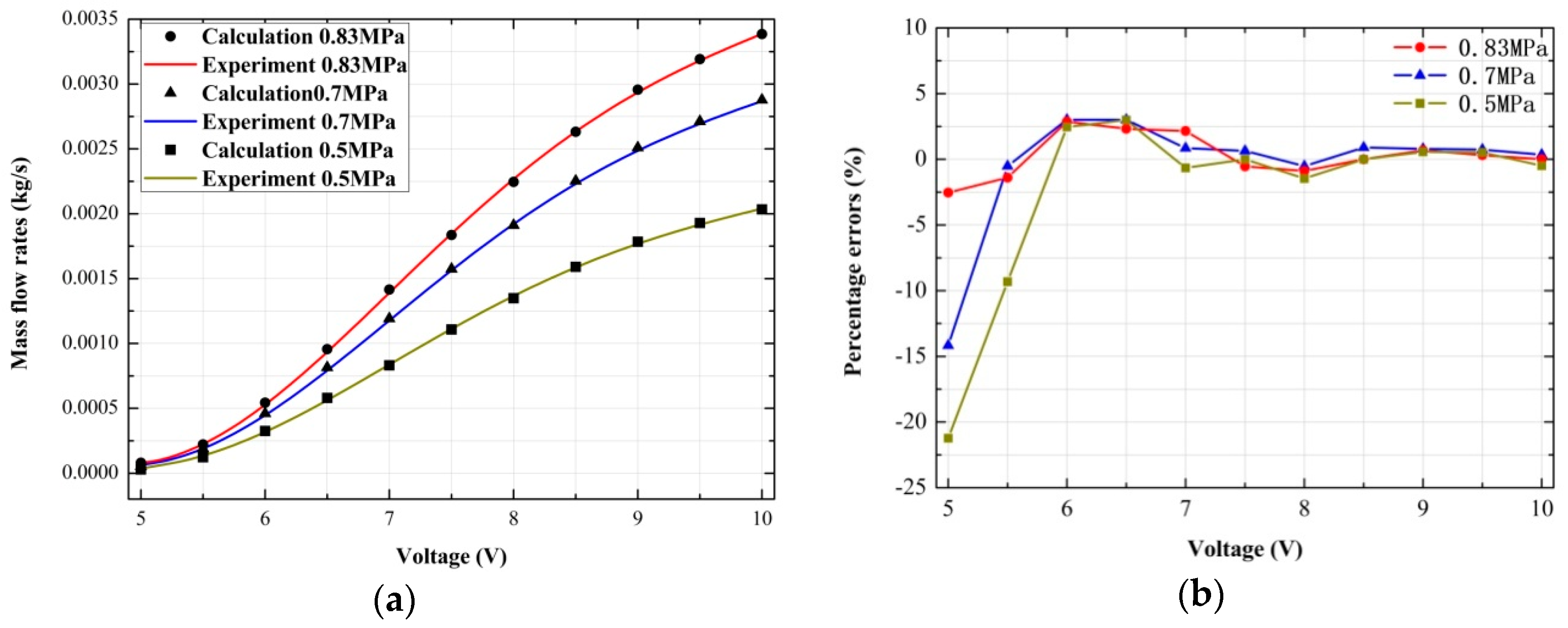
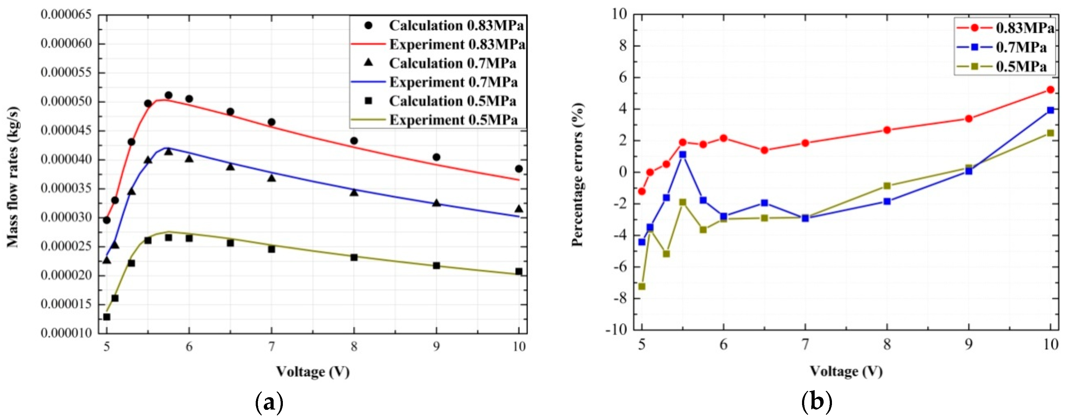
6.1. Verification of the Mass Flow Rates of the Proportional Valve
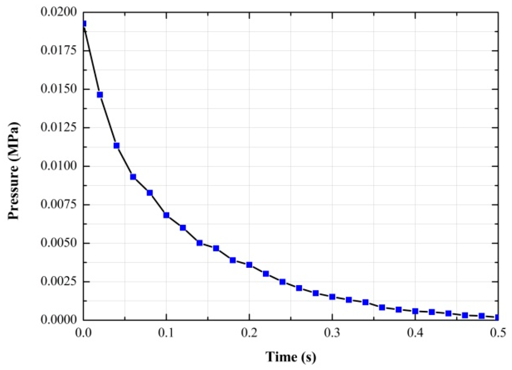
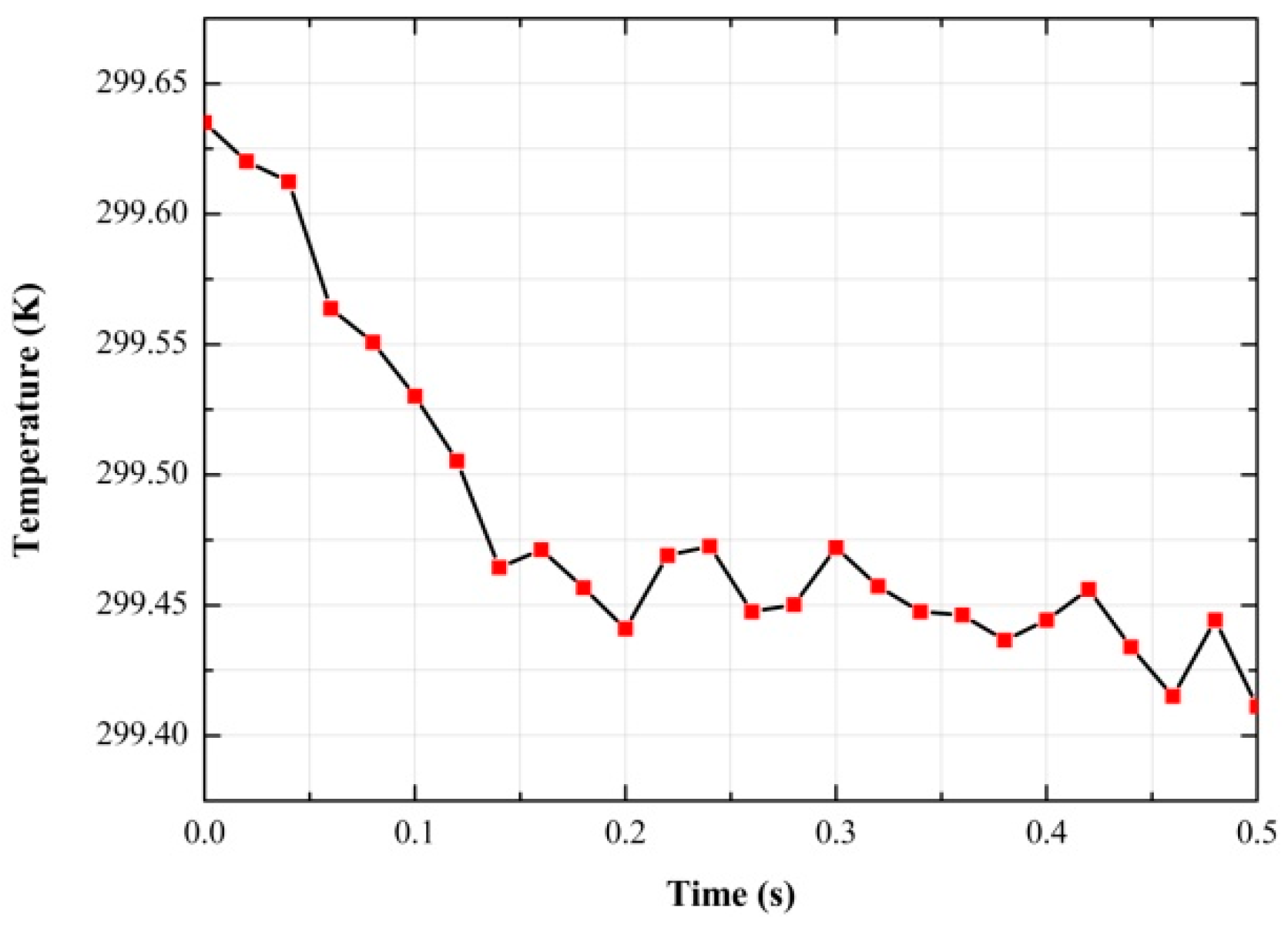
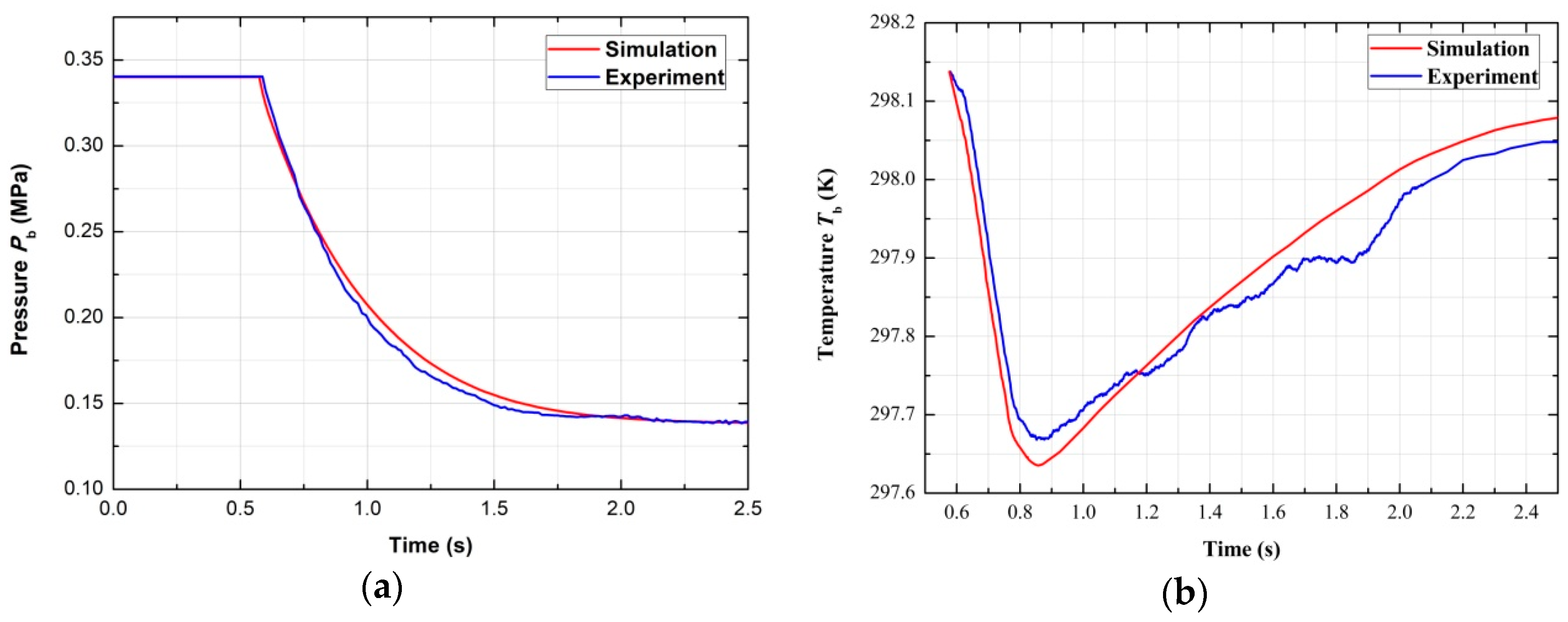
6.2. Charging and Discharging of the Chamber with a Certain Volume
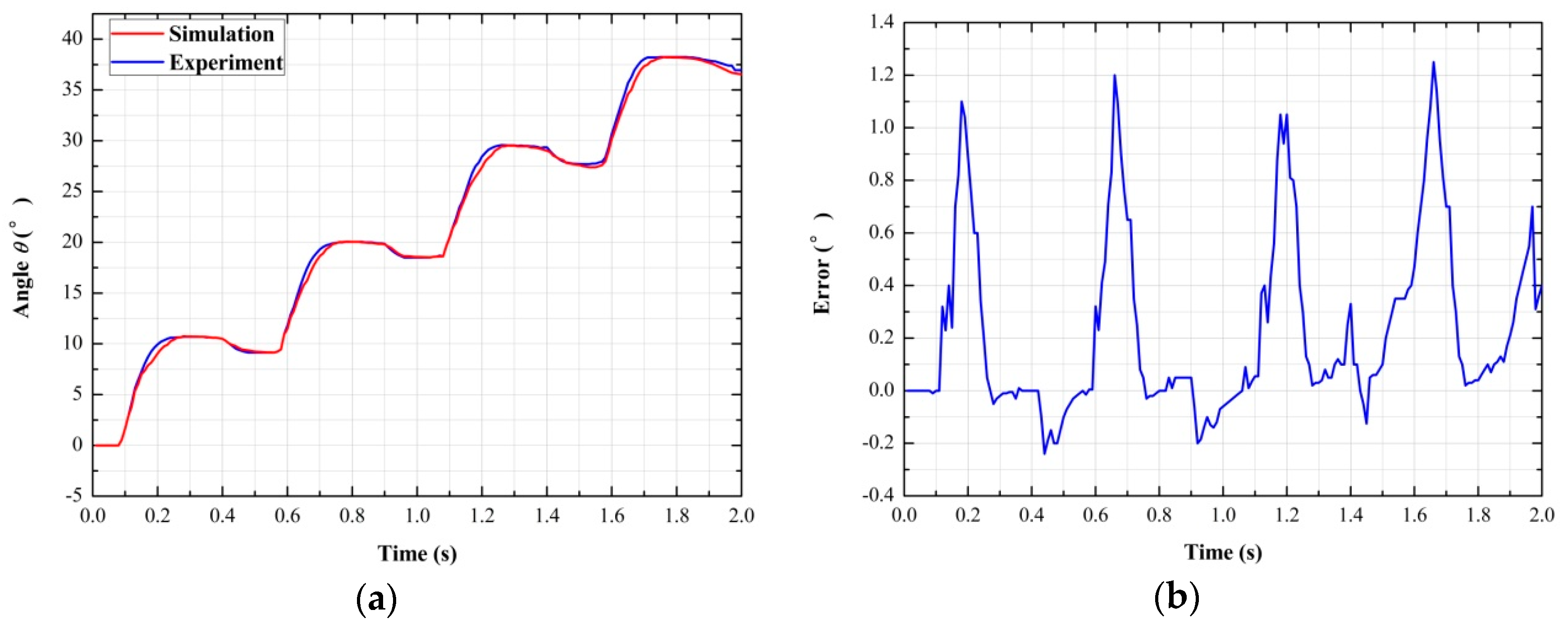
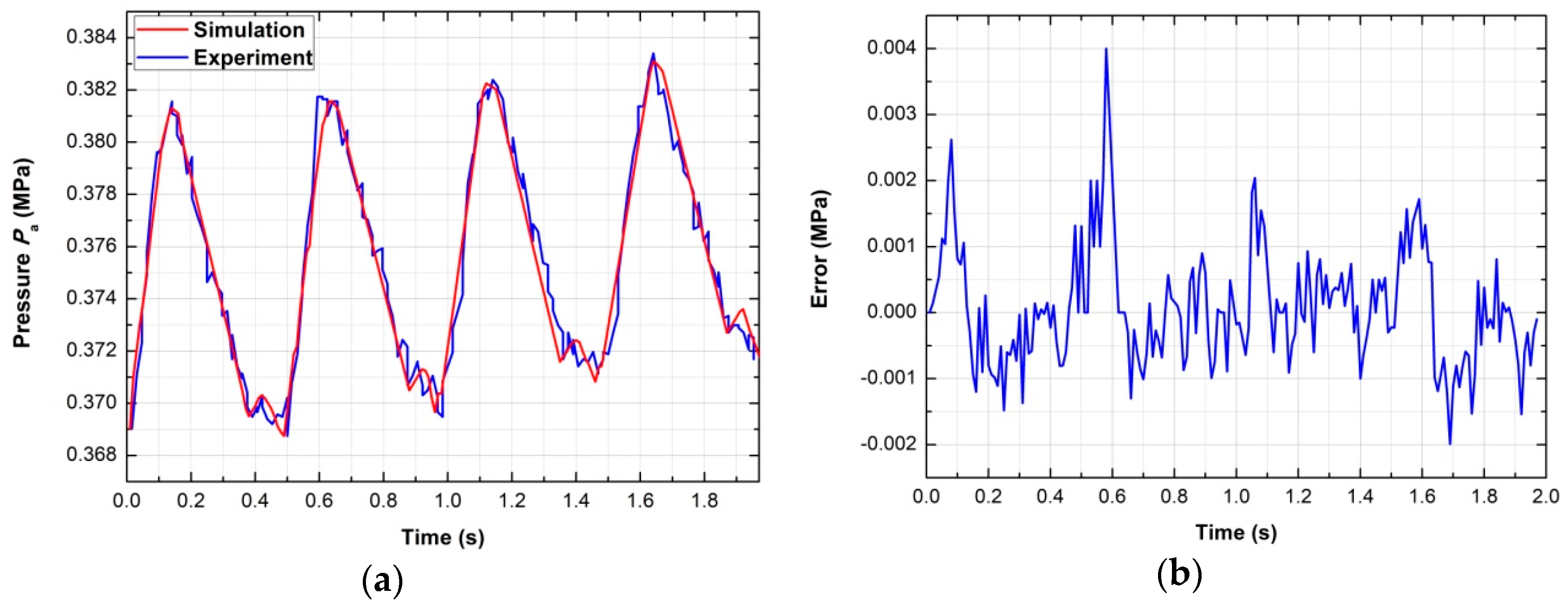
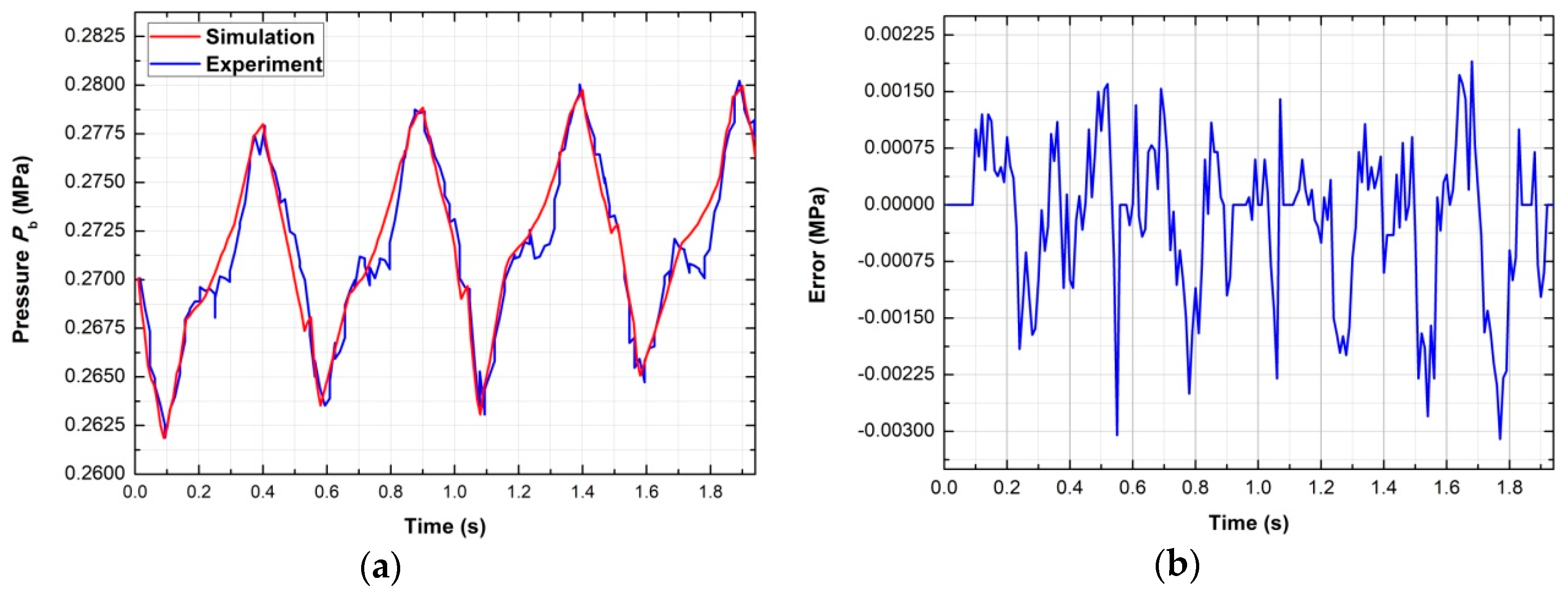
6.3. Response Verification of the Valve-Controlled Actuator System
7. Conclusions
Author Contributions
Funding
Acknowledgments
Conflicts of Interest
Nomenclature
| effective area of the actuator piston [m2] | |
| half the width of the spool shoulder [m] | |
| viscous friction coefficient [N·s/rad] | |
| critical pressure ratio | |
| sonic conductance [L3/(s·bar)] | |
| area conversion coefficient and flow coefficient of the orifice | |
| mass heat capacity at constant volume and mass heat capacity at constant pressure [J/(kg·K)] | |
| pitch diameter of the pinion [m] | |
| inner diameter of the sleeve [m] | |
| diameter of the spool shoulder [m] | |
| Coulomb friction force, driving force for the piston and the maximum static friction force [N] | |
| net inflow energy of gas [J] | |
| heat transfer coefficient between the gas and the inner wall of two chambers [W/(K·m2)] | |
| length of the clearance [m] | |
| moment of inertia of the gear [kg·m2] | |
| initial length of the clearance [m] | |
| mass flow rate of the gas flowing from port 1 to chamber a or b [kg/s] | |
| mass flow rate of the gas flowing through port 3 or 5 [kg/s] | |
| mass flow rate of the gas in chamber a or b [kg/s] | |
| mass flow rate of gas when the spool moves in the opposite direction [kg/s] | |
| mass of the gas in chamber a or b [kg] | |
| mass of a single piston [kg] | |
| pressure of the gas micelle in the clearance [MPa] | |
| a—chamber pressure, b—chamber pressure, atmospheric pressure and supply pressure [MPa] | |
| gas heat given by the outside [J] | |
| gas constant [J/(kg·K)] | |
| radius of the circular hole [m] | |
| physical area of the orifice in the horizontal direction or the vertical direction [m2] | |
| ; | effective area of the orifice when the spool moves forward or reverse [m2] |
| inner wall areas of two chambers [m2] | |
| a—chamber temperature, b—chamber temperature, room temperature and supply temperature [K] | |
| time [s] | |
| thermodynamic energy change in a chamber [J] | |
| velocity of the gas micelles in the horizontal direction [m/s] | |
| initial volume of chamber a or b [m3] | |
| work done to the outside [J] | |
| spool displacement [m] | |
| displacement of the piston [m] | |
| positive constant | |
| rotation angle of the actuator [rad] | |
| angular velocity of the actuator [rad/s] | |
| Stribeck speed [rad/s] | |
| isentropic index | |
| viscosity coefficient of the gas [Pa·s] | |
| atmospheric density [kg/m3] |
References
- Shi, Y.; Wu, T.; Cai, M.; Wang, Y.; Xu, W. Energy conversion characteristics of a hydropneumatic transformer in a sustainable-energy vehicle. Appl. Energy 2016, 171, 77–85. [Google Scholar] [CrossRef]
- Jia, G.; Xu, W.; Cai, M.; Shi, Y. Micron-sized water spray-cooled quasi-isothermal compression for compressed air energy storage. Exp. Therm. Fluid Sci. 2018, 96, 470–481. [Google Scholar]
- Zhang, Y.M.; Cai, M.L. Overall life cycle comprehensive assessment of pneumatic and electric actuator. Chin. J. Mech. Eng. 2014, 27, 584–594. [Google Scholar] [CrossRef]
- Shaw, D.; Yu, J.-J.; Chieh, C. Design of a hydraulic motor system driven by compressed air. Energies 2013, 6, 3149–3166. [Google Scholar] [CrossRef]
- Ning, F.; Shi, Y.; Cai, M.; Wang, Y.; Xu, W. Research progress of related technologies of electric-pneumatic pressure proportional valves. Appl. Sci. 2017, 7, 1074. [Google Scholar] [CrossRef]
- Saravanakumar, D.; Mohan, B.; Muthuramalingam, T. A review on recent research trends in servo pneumatic positioning systems. Precis. Eng. 2017, 49, 481–492. [Google Scholar] [CrossRef]
- Shearer, J.L. Study of pneumatic processes in the continuous control of motion with compressed air-I. Trans. ASME 1956, 233–242. [Google Scholar]
- Zhang, Y.; Li, K.; Wei, S.; Wang, G. Pneumatic Rotary Actuator Position Servo System Based on ADE-PD Control. Appl. Sci. 2018, 8, 406. [Google Scholar] [CrossRef]
- Li, K.; Zhang, Y.; Wei, S.; Yue, H. Evolutionary Algorithm-Based Friction Feedforward Compensation for a Pneumatic Rotary Actuator Servo System. Appl. Sci. 2018, 8, 1623. [Google Scholar] [CrossRef]
- Rao, Z.; Bone, G.M. Nonlinear modeling and control of servo pneumatic actuators. IEEE Trans. Control Syst. Technol. 2008, 16, 562–569. [Google Scholar]
- Lee, L.-W.; Li, I.-H. Wavelet-based adaptive sliding-mode control with h∞ tracking performance for pneumatic servo system position tracking control. IET Control Theory A. 2012, 6, 1699–1714. [Google Scholar] [CrossRef]
- Harris, P.G.; O’Donnell, G.E.; Whelan, T. Modelling and identification of industrial pneumatic drive system. Int. J. Adv. Manuf. Technol. 2012, 58, 1075–1086. [Google Scholar] [CrossRef]
- Van der Merwe, J.; Muller, J.; Scheffer, C. Parameter identification and evaluation of a proportional directional flow control valve model. R&D J. South Afr. Inst. Mech. Eng. 2013, 29, 18–25. [Google Scholar]
- Rad, C.-R.; Hancu, O. An improved nonlinear modelling and identification methodology of a servo-pneumatic actuating system with complex internal design for high-accuracy motion control applications. Simul. Model. Pract. Theory 2017, 75, 29–47. [Google Scholar] [CrossRef]
- Cai, M. Second: Fixed volume cavity charging and discharging. Hydraul. Pneum. Seals 2007, 27, 43–47. (In Chinese) [Google Scholar]
- Valdiero, A.C.; Ritter, C.S.; Rios, C.F.; Rafikov, M. Nonlinear mathematical modeling in pneumatic servo position applications. Math. Probl. Eng. 2011, 2011, 472903. [Google Scholar] [CrossRef]
- Bai, Y.-H.; Li, X.-N. Dual-loop Control Strategy with Friction Compensation for Pneumatic Rotary Actuator Position Servo System. J.-Nanjing Univ. Sci. Technol. 2006, 30, 216. [Google Scholar]
- Xu, J.; Qiao, M.; Wang, W.; Miao, Y. Fuzzy PID control for AC servo system based on Stribeck friction model. In Proceedings of the 2011 6th International Forum on Strategic Technology, Harbin, China, 22–24 August 2011; IEEE: Harbin, China, 2011; Volume 2, pp. 706–711. [Google Scholar]
- Kong, X.; Wang, Y.; Jiang, S. Friction Chatter-compensation Based on Stribeck Model. J. Mech. Eng. 2010, 46, 68–73. [Google Scholar] [CrossRef]
- Zhang, S.; Chen, J.B.; Wang, T.; Fan, W. Nonlinear modeling and simulation of pneumatic servo position system of rodless cylinder. In Applied Mechanics and Materials; Trans Tech Publications: Zürich, Switzerland, 2012; Volume 130, pp. 3493–3497. [Google Scholar]
- Peter, B. Pneumatic Drives System Design, Modeling and Control; Springer: Berlin/Heidelberg, Germany, 2007. [Google Scholar]
- Sanville, F. A new method of specifying the flow capacity of pneumatic fluid power valves. Hydraul. Pneum. Power 1971, 17, 120–126. [Google Scholar]
- Daugherty, R.L.; Ingersoll, A.C. Fluid Mechanics; McGraw-Hill Book Company, Inc.: New York, NY, USA, 1954. [Google Scholar]
- Zhan, Y.J.; Wang, T.; Wang, B. Study on friction characteristics of energizing pneumatic cylinders. In Advanced Materials Research; Trans Tech Publications: Zürich, Switzerland, 2014; Volume 904, pp. 306–310. [Google Scholar]
- Carneiro, J.; de Almeida, F.G. Heat transfer evaluation of industrial pneumatic cylinders. Proc. Inst. Mech. Eng. Part 1 2007, 221, 119–128. [Google Scholar] [CrossRef]


| No. | Component | Model | Parameter |
|---|---|---|---|
| 1 | Air compressor | PANDA 750-30L | Maximum supply pressure: 0.8 MPa |
| 2 | Air service unit | AC3000-03 | Maximum working pressure: 1.0 MPa |
| 3 | Pressure transmitter | CYYZ11 | Range: 0–0.6 MPa; accuracy: 0.1% FS |
| 4 | Proportional direction control valve | FESTO MPYE-5-M5-010-B | Rated flow rate: 100 L/min |
| 5 | Rotary encoder | GSS06-LDH-RAG20000Z1 | Resolution: 20,000 P/R |
| 6 | Pneumatic rotary actuator | SMC MSQA30A | Bore: 30 mm; stroke: 190 ° |
| 7 | Data acquisition card | NI PCI-6229 | 32-channel analog input; 4-channel analog output; 32-bit counter |
| IPC | IPC-610H | 32-bit processor; standard configuration |
| Parameter | Value |
|---|---|
| 1.010 × 10⁻³ (m) | |
| 1.000 × 10⁻³ (m) | |
| 6.000 × 10⁻³ (m) | |
| 6.023 × 10⁻³ (m) | |
| 0.5382 | |
| 3.4636 × 10⁻⁴ (m2) | |
| 0.014 (m) | |
| 0.183× 10⁻⁴ (Pa·s) | |
| 1.5106348× 10⁻² (m2) | |
| 1.5106348 × 10⁻² (m2) | |
| 0.210 (kg) | |
| 1.678 × 10⁻⁴ (kg·m2) | |
| 2.000 × 10⁻³ (m) |
| Component | Model | Parameter |
|---|---|---|
| Flow sensor 1 | FESTO SFAH-5U-Q6S-PNLK-PNVBA-M8 | Range: 0.1–5 L/min; accuracy: 2% o.m.v. + 1% FS |
| Flow sensor 2 | FESTO SFAB-200U-HQ8-2SV-M12 | Range: 2–200 L/min; accuracy: 3% o.m.v. + 0.3% FS |
| Temperature transmitter (Thermocouple) | TT-K-36 (K-Type, diameter: 0.1 mm) | Range: 0–260 °; accuracy: 0.4% FS |
| Parameter | Value |
|---|---|
| 10.60 (N) | |
| 6.03 (N) | |
| 0.14 (rad/s) | |
| 0.85 (N·rad−1·s−1) |
| Driving Voltage | 5 V | 5.1 V | 5.3 V | 5.5 V | 5.75 V | 6 V | 6.5 V | 7 V | 8 V | 9 V | 10 V |
|---|---|---|---|---|---|---|---|---|---|---|---|
| = 0.5 MPa | 0.2763 | 0.3143 | 0.4046 | 0.4563 | 0.475 | 0.4813 | 0.4863 | 0.4863 | 0.4863 | 0.4863 | 0.4863 |
| = 0.7 MPa | 0.394 | 0.4353 | 0.5583 | 0.6263 | 0.6743 | 0.6713 | 0.6763 | 0.6763 | 0.6763 | 0.6763 | 0.6763 |
| = 0.83 MPa | 0.4813 | 0.5263 | 0.6613 | 0.7513 | 0.7863 | 0.7913 | 0.7963 | 0.7963 | 0.7963 | 0.7963 | 0.7963 |
© 2019 by the authors. Licensee MDPI, Basel, Switzerland. This article is an open access article distributed under the terms and conditions of the Creative Commons Attribution (CC BY) license (http://creativecommons.org/licenses/by/4.0/).
Share and Cite
Zhang, Y.; Li, K.; Wang, G.; Liu, J.; Cai, M. Nonlinear Model Establishment and Experimental Verification of a Pneumatic Rotary Actuator Position Servo System. Energies 2019, 12, 1096. https://doi.org/10.3390/en12061096
Zhang Y, Li K, Wang G, Liu J, Cai M. Nonlinear Model Establishment and Experimental Verification of a Pneumatic Rotary Actuator Position Servo System. Energies. 2019; 12(6):1096. https://doi.org/10.3390/en12061096
Chicago/Turabian StyleZhang, Yeming, Ke Li, Geng Wang, Jingcheng Liu, and Maolin Cai. 2019. "Nonlinear Model Establishment and Experimental Verification of a Pneumatic Rotary Actuator Position Servo System" Energies 12, no. 6: 1096. https://doi.org/10.3390/en12061096
APA StyleZhang, Y., Li, K., Wang, G., Liu, J., & Cai, M. (2019). Nonlinear Model Establishment and Experimental Verification of a Pneumatic Rotary Actuator Position Servo System. Energies, 12(6), 1096. https://doi.org/10.3390/en12061096