Article

Exergy Evaluation of a Heat Supply System with Vapor Compression Heat Pumps

Institute of Environmental Engineering, Faculty of Civil and Environmental Engineering, Poznań University of Technology, Ul. Berdychowo, 460-965 Poznań, Poland
*
Author to whom correspondence should be addressed.
Energies 2019, 12(6), 1028; https://doi.org/10.3390/en12061028
Submission received: 5 February 2019 / Revised: 7 March 2019 / Accepted: 9 March 2019 / Published: 16 March 2019

Abstract

:
The vapor compression heat pumps are very popular solutions regarding heat supply systems of modern, low energy buildings. It is partly due to the fact that they are treated as a sustainable heat supply. The question arises: Can a vapor compression heat pump be treated as a sustainable heat supply? To answer this question; the exergy model of a heat pump system operation has been proposed. The proposed model has been employed for evaluation of exergy efficiency of an existing heat supply system equipped with two heat pumps installed in an educational building located on the campus of Poznan University of Technology, Poznan, Poland. The analysis shows that the system exergy efficiency decreases with an increase in outdoor temperature and its values are in the range of 10.9% to 42.0%. The primary exergy efficiency, which considers the conversion of fossil fuel into electricity, is on average 3.2 times lower than the system exergy efficiency for the outdoor temperature range of −9 °C to 11 °C. The performed analysis allowed for the identification of a set of solutions that may increase the exergy and primary exergy efficiency of the system. The first solution is to cover a part of the electricity demand by a renewable energy source. The second proposition is to apply a low-temperature emission system for heating. The third idea is to apply a district heating network as the heat supply instead of the heat pump. The conclusion is that the exergy performance of systems with heat pumps is rather poor because they generate low-quality heat from high-quality electricity. The best way to improve the primary exergy efficiency of a heat pump system is to power the system by electricity generated from a renewable energy source.

1. Introduction

The vapor compression heat pumps are thought to be a sustainable solution for heating. Due to this, they are becoming more and more commonly used in modern, low-energy buildings. However, can a vapor compression heat pump be treated as a sustainable heat supply? This study is an attempt to answer the question. To do this, the exergy model of a heat pump operation has been proposed. The exergy balance analysis is based on the first and the second law of thermodynamics. This enables both quantitative and qualitative evaluation of energy flows in thermodynamically open systems. The quality of an amount of energy is defined as the maximal work potential of a system as it achieves equilibrium with the surrounding environment. The environment may be both an unlimited energy source and an energy sink.
The driving exergy of heat pumps is the most valuable form of exergy which is electricity. The produced useable exergy is a low-temperature heat—the energy form of the lowest exergy. In some cases, as described in the paper, the exergy performance of a heat supply system with a heat pump is not very good. In fact, the use of traditional solutions, such as a heat exchanger connected to a district heating network supplied from an energy efficient combined heat and power (CHP) plant, may allow for a significant reduction of driving exergy needs for the system operation. Researchers often study the exergy performance of individual components of a heat pump to determine which component is the main source of irreversibility. While designing a heat pump system, the system designer chooses a heat pump offered by a manufacturer and has no influence on the device components. However, the designer has an impact on operational conditions, choice of the heat source and heat sink temperatures, and the electrical power source. For this reason, in this paper, the exergy analysis of a heat supply system with heat pumps is presented. Moreover, three possible improvement measures are proposed and evaluated. The analysis was performed for an existing vertical-bore, ground source heat pump system installed in one of Poznan University of Technology buildings.

2. Literature Review

Schmidt [1] claimed that calculations based on the first law of thermodynamics and primary energy concept alone are insufficient for the full understanding of all important aspects of energy utilization. Application of low exergy design principles decreases the exergy demand in the built environment and related energy suppliers. This results in a reduction of CO2 emissions due to the use of more efficient energy conversion processes.
Even though the exergy approach gives a more complete picture of energy flows, the energy balance analysis remains the more common method of energy systems evaluation. However, some investigations have been conducted by researchers in the exergy-based evaluation of heat pumps performance. Cakir et al. [2] performed an experimental study using an air-to-water heat pump and investigated the relationship between the exergy performance of the heat pump and its components. The authors also analyzed the effects of working conditions of the components on the system performance. It turned out that the influence of the components on the exergy performance varies with the heat source temperature. Li et al. [3] performed an exergy analysis of both ground source heat pump and air source heat pump in the cooling mode. The authors showed that the ground source heat pump consumes less exergy than the air source heat pump. The reason is that the ground source heat pump drains “cool exergy” from the ground, while no “cool exergy” is available in the surrounding air. The second reason is a smaller temperature difference between cooling water and heat source for the ground source heat pump. Esen et al. [4] studied the energetic and exergetic performance of a ground source heat pump as a function of the horizontal ground heat exchanger depth for heating purpose. The results confirmed that the energy and exergy efficiencies of the heat pump rise with an increase in the heat source temperature for the heating season. Moreover, it was confirmed that an increase in the surrounding environment temperature causes a decrease in both efficiencies. The conclusion drawn by Esen et al. was confirmed by Verda et al. [5]. They compared the exergy performance of ground source heat pumps differing in depths of the horizontal ground heat exchanger. The authors showed that the deeper installation allows an increase of exergy output. Habtamu et al. [6] performed a more detailed exergy analysis of a ground source heat pump coupled with vertical ground loop pipes for heating application. The authors took into consideration the impact of the ground depth, the brine mass flow rate, types of refrigerants, the heat delivery temperature and the reference state of the surrounding environment. In the study by Abbasi et al. [7] regarding exergy and sustainability analysis of a ground source heat pump that is coupled with a photovoltaic system for cooling and heating application, the authors evaluated the exergy destruction rate and sustainability indices of different components of the system. They considered the influence of monthly thermal load variations on the system performance. They concluded that the system caused significant exergy losses, especially in the heating season. The exergy destruction occurred mostly in PV panels, condenser, and evaporator. Hu et al. [8] presented energy and exergy analysis of a ground source heat pump installed in a public building under five different control strategies. Parameters, such as exergy efficiency, exergy loss, COP and energy consumption, were calculated. The proposed control strategies were compared with the actual control system—manual operation. It was concluded that the best control strategy is variable flow control by variable speed pumps. Menberg et al. [9] developed a thermodynamic model of a hybrid ground source heat pump system with a supplementary boiler for heating and cooling. The study showed that for heating and cooling different system components attribute most to the overall exergy loss in the system. The authors concluded that improvement measures, such as changes in the operational settings and an upgrade of the building envelope, have a more significant impact on heating performance than on cooling performance. Moreover, decreasing thermal loads is a more effective improvement measure than changes in the operational settings of energy supply systems. Ozgener et al. [10] developed an energetic and exergetic model of two ground source heat pump systems—a solar assisted vertical ground source heat pump and a horizontal ground source heat pump. The authors based their investigation on experimental data. The solar assisted vertical ground source heat pump achieved higher values of COP and exergy efficiency. Cho [11] performed a comparative study on the performance and exergy efficiency of a solar hybrid heat pump using refrigerants R22 and R744. The author ran experimental tests on a sunny and cloudy day. Then he determined the COP values and the exergy losses. The exergy efficiency of the heat pump using the refrigerant R22 was higher than that of the R744. Bi et al. [12] performed a comprehensive exergy analysis of a ground-source heat pump system for building heating and cooling. The authors derived the analytical formulae of various exergy indices. It was shown that the indices should be used integratively. The largest exergy losses occurred in the compressor. The lowest exergy efficiency and thermodynamic perfect degree were achieved in the ground heat exchanger. Moreover, it was concluded that the exergy loss of the system for the heating mode is larger than for the cooling mode. Hepbasli [13] performed an exergy analysis of a solar assisted domestic hot water tank integrated with a ground source heat pump for a residence. The author derived exergy relations for each system component and the whole system. Both experimental and assumed values were used for the calculations. The exergy efficiency of the whole system was 44.06% at the reference state of 19 °C and 101.325 kPa. The greatest exergy destruction occurred in the condenser. Saloux et al. [14] proposed an exergy modeling approach for heat pumps that do not require a knowledge of refrigerant thermodynamic parameters. The energy and exergy balance is based on energy terms and energy quality factors. A mathematical method for refrigerant operating temperatures calculation is proposed. The authors presented a graphical exergy representation that allows localizing exergy losses sources. The model was applied to water-to-water and air-to-air heat pumps. The results were compared with the reference ones that were calculated using the classical thermodynamic cycle method. Stanek et al. [15] performed an exergetic and thermo-ecological assessment of a heat pump powered by electricity generated from renewable sources. The authors pointed out that the ecological efficiency of heat pumps is dependent on their performance and on the energy mix used for the electricity production. The efficiency can be improved by renewable energy sources application. The authors evaluated a heat pump system using thermo-ecological cost (TEC) indices. The analyzed system consisted of an electricity-driven heat pump, and PV panels or wind turbines that acted as the priority electricity source.
The aforementioned studies are examples of the exergy analysis application. However, the literature survey showed that the energy analysis is still the more popular method of energy systems evaluation. It is used both by researchers and policymakers. Unfortunately, energy analysis is a limited tool to analyze vapor compression heat pumps operation. It is due to the fact that the energy balance equation considers the quantity of various energy forms without distinguishing their quality. That is why the exergy approach based on the first and the second law of thermodynamics has to be used to evaluate heat pump operation. Application of the exergy analysis may contribute to a more rational consumption of energy sources due to a reduction of high-quality non-renewable energy sources consumption. The exergy model of a heat pump and a heat supply system equipped with heat pumps are presented below.

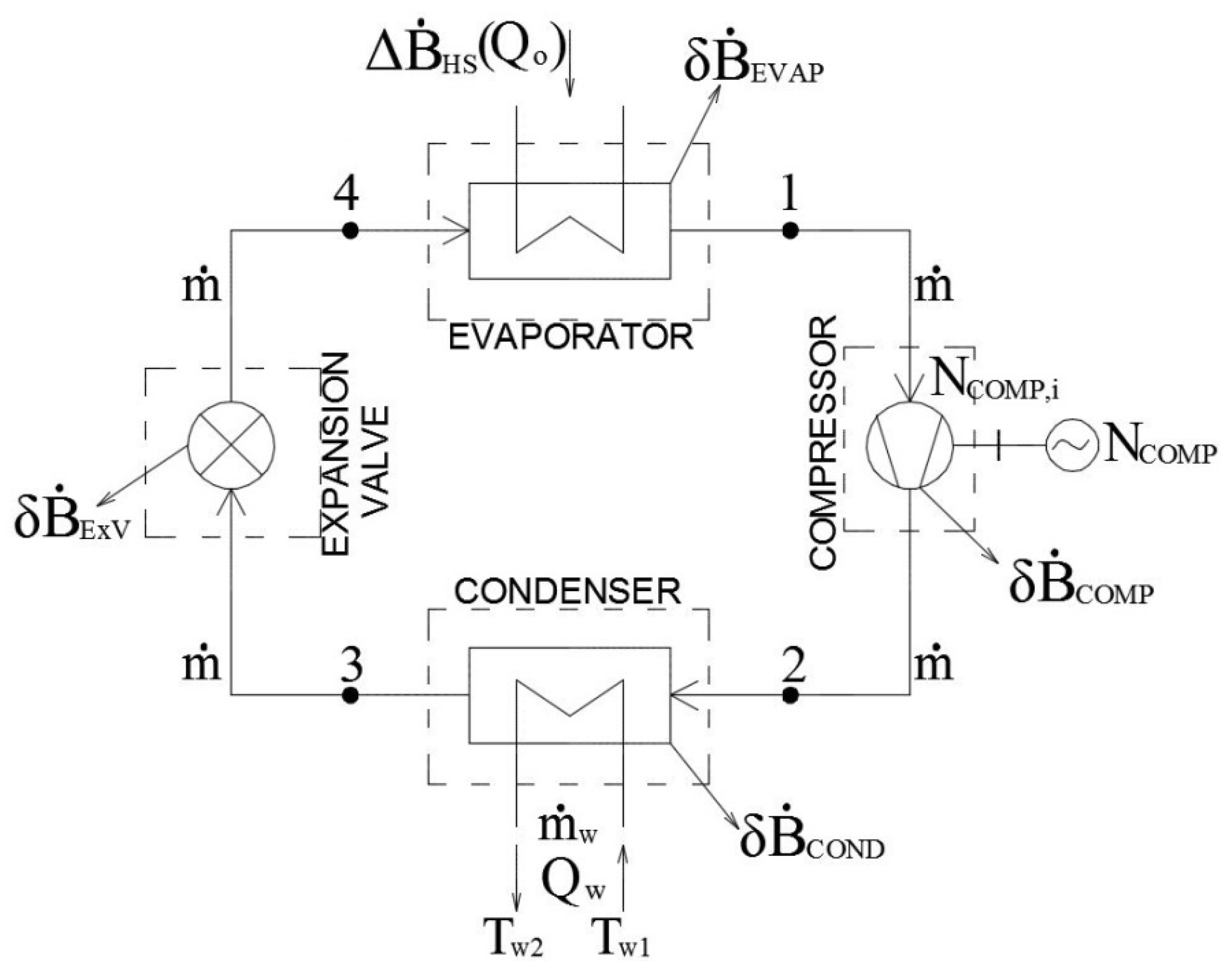
3. Exergy Model of a Vapor Compression Heat Pump

Exergy balance equations of heat pump components were described in [16]. Figure 1 shows the exergy model of a heat pump. The total exergy loss is the sum of the exergy losses caused by all components of the heat pump: the evaporator, the compressor and electric motor, the condenser and the expansion valve. All real thermodynamic processes are irreversible. It means that they cause exergy destruction. For this reason, the exergy balance equations contain the internal exergy losses of the system δ B ˙ . The exergy balance equation can be presented in a differential form—Equation (1).
B ˙ in = δ B ˙ + B ˙ out use + δ B ˙ ext ± Δ B ˙ HS
where:
  • B ˙ in Flux of exergy entering the control volume of a thermodynamically open system, (W)
  • B ˙ out use Flux of useable exergy leaving the control volume of a thermodynamically open system, (W)
  • δ B ˙ Flux of internal exergy losses of a thermodynamically open system, (W)
  • δ B ˙ ext Flux of external exergy losses of a thermodynamically open system, (W)
  • Δ B ˙ HS Flux of change of exergy of an external heat source being in contact with a thermodynamically open system, (W)
The exergy balance equations related to the heat pump components are based on the relation between the exergy flux entering B ˙ in and leaving B ˙ out the control volume—Equation (2). The difference between them constitutes the exergy loss occurring in the component δ B ˙ component .
B ˙ in B ˙ out = δ B ˙ component
Table 1 shows the exergy balance equations of the heat pump components. The nomenclature corresponds to Figure 1. T o is the temperature of the surrounding environment and η COMP , em is the electro-mechanical efficiency of the compressor.
The exergy analysis allows calculating exergy efficiency η b , HP and primary exergy efficiency η b , HP * of the heat pump—Equations (3) and (4), respectively. The primary exergy efficiency enables an objective evaluation of the system performance. It includes the efficiency of electricity production and distribution η P , and the ratio between specific chemical exergy of the fuel used in electricity production and its low heating value β P [17,18].
η b , HP = B ˙ use N COMP + Δ B ˙ HS
η b , HP * = B ˙ use N COMP · β P η P + Δ B ˙ HS
B ˙ use is the flux of useable exergy—Equation (5). The useable exergy is the physical exergy of the heating water.
B ˙ use = m ˙ w · c w · ( T w , 2 T w , 1 T o · ln T w , 2 T w , 1 )
where
  • m ˙ w Mass flow of heating water through the condenser, (kg/s)
  • c w Specific heat of water, (J/(kgK))
  • T w , 1 Temperature of water entering the condenser, (K)
  • T w , 2 Temperature of water leaving the condenser, (K)

4. Case Study Description

The analysis was performed for an existing vertical-bore, ground source heat pump system installed in an educational building located on the campus of Poznan University of Technology, Poznan, Poland. The building of the educational center of the Faculty of Chemical Technology of Poznan University of Technology consists of four above-ground stories and one underground story—parking area. The above-ground stories contain auditorium halls, laboratories and consulting rooms. The building has a total area of 12,800 m2 and serves 2700 students and 300 employees. It is built on the plane of H letter with two east and west wings joined by a passage. The analyzed system is equipped with two heat pump units that produce 47/57 °C heating water in winter. Maximal heating load of the building is 1650.8 kW. The heat pump system has a capacity of 350 kW and is supplemented by a heat exchanger connected to a district heating network. When the heating load exceeds 350 kW the systems work together. However, the heat pump takes priority. The systems are linked through a buffer tank. The heat pump system adjusts the heating water temperature to actual needs depending on the outdoor temperature. The ground heat exchanger is composed of 51 vertical U-pipes. The depth of the U-pipes is 170 m. The heat transfer medium in the primary circuit is a 15% solution of propylene glycol. Table 2 shows the main devices list and their characteristics.
The electricity powering the compressors and the circulation pumps is produced in a hard coal-fired condensing power plant and distributed via a power grid. The energy efficiency of the electricity production and distribution system equals 33%. The supplementary heat is supplied through the district heating network from a hard coal-fired counter pressure combined heat and power plant (CHP). Energy efficiency of the CHP plant is 80%. The annual co-generation factor e equals 0.3.

5. Case Study—Exergy Evaluation

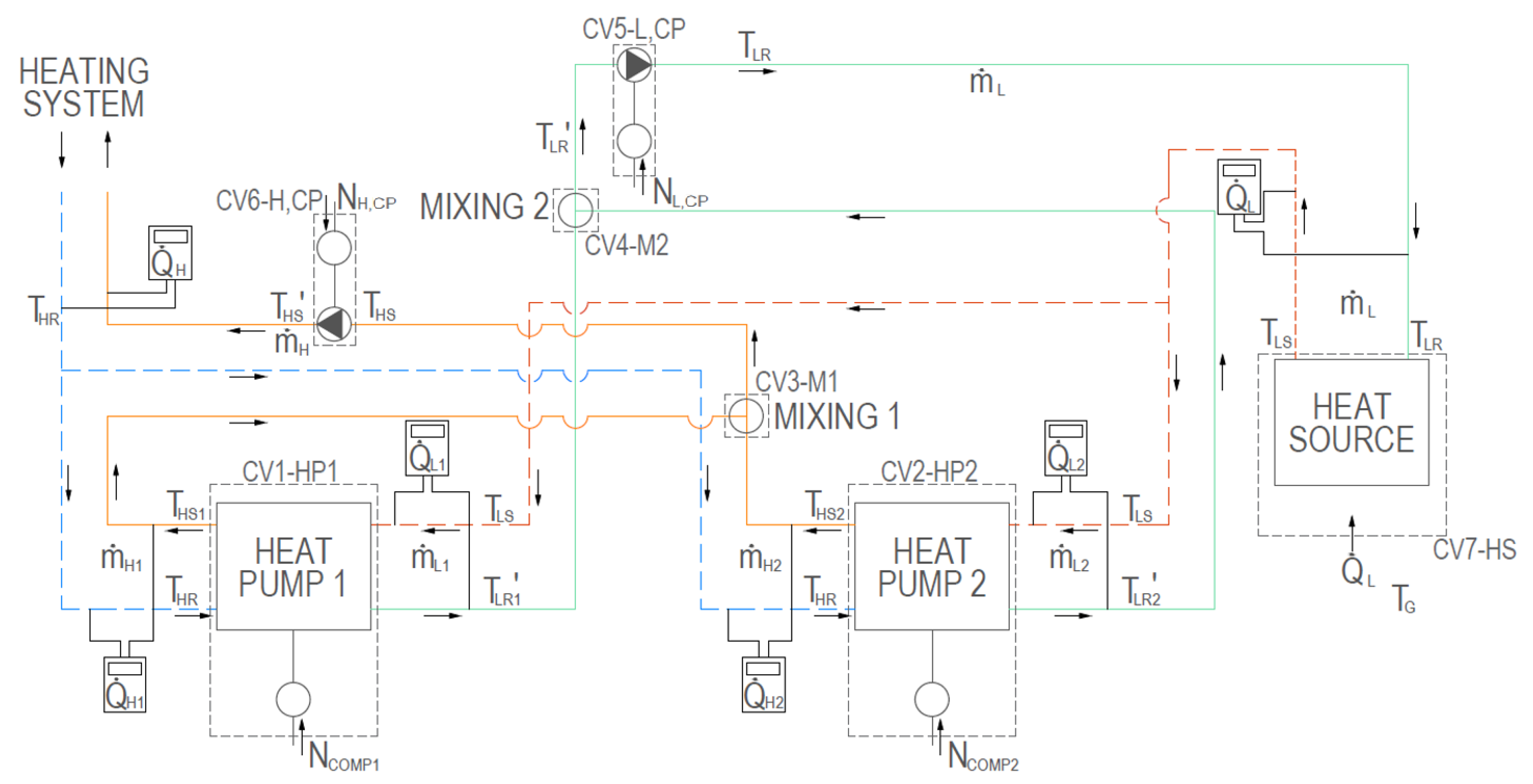
Model of the Heat Supply System with Heat Pumps

To perform the exergy analysis of the heat supply system with heat pumps, a calculation model was created. The model is presented in Figure 2. There are seven control volumes (CV) covering seven system components whose operation causes exergy losses. Table 3 presents the list of the control volumes and the equations describing the exergy fluxes entering and leaving the control volumes. The flux of exergy loss in each control volume can be calculated using the relation—Equation (2).
The exergy efficiency of the heating system with heat pumps can be derived using two methods. The first method assumes that the sum of the exergy efficiency and relative exergy losses of all system components is equal to 1—Equation (6). The second method is related to the definition of exergy efficiency—exergy efficiency is the ratio between the useable exergy and the driving exergy—Equation (7), where the useable exergy is the exergy of the heating water—Equation (8). The two methods must give the same result. The primary exergy efficiency was calculated by the formula—Equation (9).
η b , sys = 1 i δ B ˙ i N COMP 1 + N COMP 2 + N H , CP + N L , CP + Δ B ˙ HS
η b , sys = δ B ˙ use N COMP 1 + N COMP 2 + N H , CP + N L , CP + Δ B ˙ HS
B ˙ use = m ˙ H · c W · ( T HS T HR T o · ln T HS T HR )
η b , sys * = B ˙ use β P · ( N COMP 1 + N COMP 2 + N H , CP + N L , CP ) η P + Δ B ˙ HS

6. Calculations

To perform the calculations; some assumptions were made. They are mostly based on the heating system design data. The minimal assumed outdoor temperature in Poznan equals −18 °C [19]. For this temperature, the heating load reaches the highest value of 1650.8 kW. It is assumed that the heating load falls proportionally with a decrease in the outdoor temperature achieving 0 kW at 12 °C. The heat pump has a capacity of 350 kW, which corresponds to the outdoor temperature of 5.6 °C. At this temperature, the bivalent point is reached. If the temperature is lower, the heat pump is supplemented by the extra heat source—the heat exchanger connected to the district heating network. This is shown in Figure 3 which was created using meteorological data for typical meteorological year acquired from Polish Ministry of Investment and Economic Development [20]. The total annual heat demand of the building is 2805 MWh/a. The heat pump covers 57.8% of the demand (1620 MWh/a). The supplementary heat source works 3680 h per year.
The dependence between the temperature of the heat transfer medium entering the heat pump evaporator and the outdoor temperature was derived based on exploitation data acquired from the building management system (BMS). The medium temperature rises from 5.8 °C to 10.5 °C with the increase in the outdoor temperature. Figure 4 shows the dependence between the heating water temperature and the outdoor temperature. The heating water temperature drops from 57 °C for an outdoor temperature of −18 °C to 35 °C for an outdoor temperature of 12 °C.
The calculations were performed for 13 values of outdoor temperature which are shown in the first column of Table 4. The analyzed system operation started in the year 2014. The outdoor temperature range represents the heating season outdoor conditions prevailing in the period between the years 2014 and 2018 in Poznan, Poland. The total heating load and the heating power of the heat pumps were obtained from the graph depicted in Figure 3. The maximal heat output of the heat pumps is 350 kW. Below the outdoor temperature of 5.6 °C (bivalent point), the heat pumps generate the 350 kW. The power demand of the compressors is dependent on the COP. The values of COP were computed on the basis of specific enthalpies of the refrigerant R407C at the temperatures of evaporation and condensation. Values of the temperatures were assumed based on the temperatures of the heat transfer medium entering the evaporator and of the heating water leaving the condenser. It was assumed that the temperature difference between the media and the refrigerant equals 5 K. For the calculation of the COP, the tool SOLKANE 8 [21] was used. The required power of the compressors was determined as the quotient of the heat pumps heating power and the COP. Each heat pump is equipped with four compressors which work at a constant speed (on/off). The electric power of each compressor is 15.2 kW. It was assumed that each compressor has the electro-mechanical efficiency of 90%. The heat exchanged in the evaporators was determined as the difference between the heating power of the heat pump and the internal power of the compressors. The temperature of the heat transfer medium entering the evaporator was obtained from the BMS and its mass flow was assumed to be constant and equals 25.2 kg/s (based on the operating point of the circulating pump—Table 2, the flow rate given in (m3/h) was recalculated using the glycol solution density of 1014 kg/m3). The temperature of the heat transfer medium leaving the evaporator was computed on the basis of the medium mass flow, and the heat exchanged in the evaporator. Internal efficiencies of the circulating pumps were obtained from the manufacturer data. The amount of heat extracted from the ground was calculated with Formula (10).
Q ˙ L = m ˙ L · c WG · ( T LS T LR )
where
  • m ˙ L Mass flow of the heat transfer medium, (kg/s)
  • c WG Specific heat of the heat transfer medium, (J/(kgK))
  • T LR Temperature of the heat transfer medium entering the ground heat exchanger, (K)
  • T LS Temperature of the heat transfer medium leaving the ground heat exchanger, (K)
The depth of the vertical-bore heat exchanger is 170 m, so the ground temperature was assumed to be constant and equal to 10 °C. The total mass flow of the heating water was assumed to be constant and was determined on the basis of the operating point of the circulating pump (Table 2). The flow rate given in (m3/h) was recalculated using a water density of 1000 kg/m3. The heating water mass flow equals 9.1 kg/s. The heating water temperatures were obtained from the graph depicted in Figure 4.
The energy efficiency of electricity production and distribution η P was calculated as a reciprocal of the Primary Energy Factor for generation and delivery of electricity to a building. In Poland the Primary Energy Factor equals 3 [22], so the energy efficiency of electricity production and distribution η P equals 0.33. The ratio between specific chemical exergy of the fuel used in electricity production (hard coal) and its low heating value β P equals 1.09 [16].
The aforementioned assumptions were used for the exergy analysis of the heating system.

7. Results and Discussion

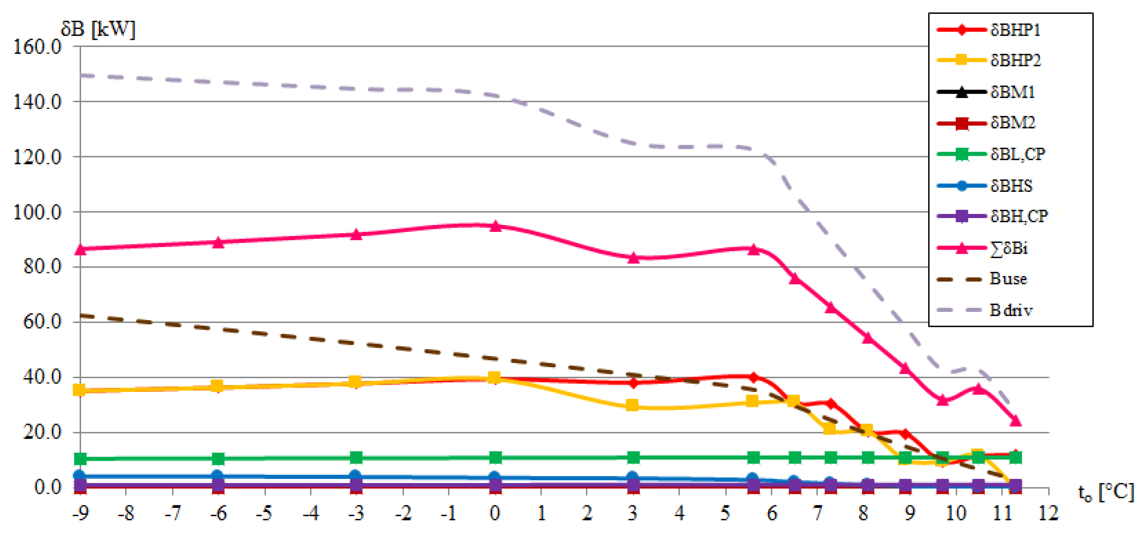
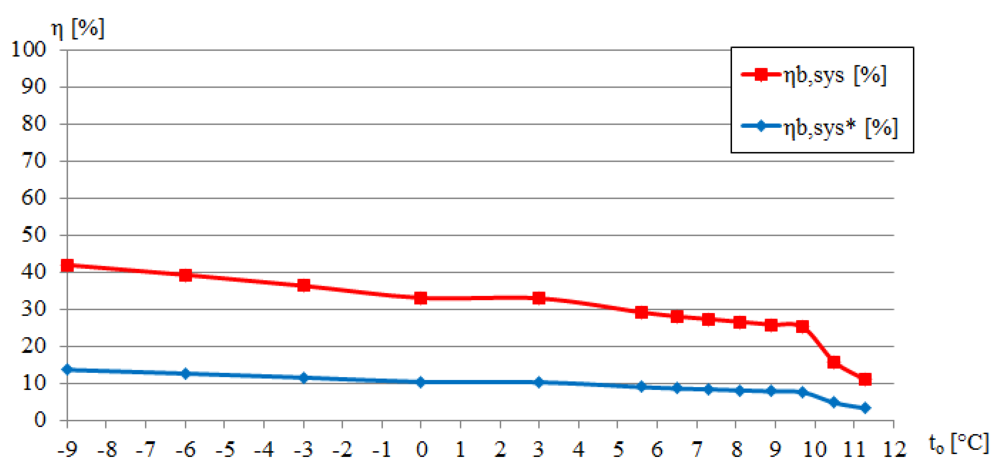
7.1. Exergy Analysis of the Actual System

The calculated exergy losses in the system components are presented in Table 5. The same results are depicted in Figure 5. Additionally, the pink line represents the total exergy losses of the overall system δ B i . For the outdoor temperatures below 0 °C, despite the fact that the heating power provided by the heat pumps is constant, the total flux of exergy losses increases from 86,755 W for the outdoor temperature of −9 °C to 95,118 W for 0 °C. For this temperature range, the heat pumps work at full capacity, so all eight compressors are on. It means that the driving exergy flux, which enters the system through the operation of the compressors, is constant in this temperature range. However, the useable exergy flux (exergy of the useable heat transferred by the heating water) decreases with an increase in the outdoor temperature. The outdoor temperature acts as the reference temperature. The difference between the outdoor temperature and the heating water temperature represents the maximal work potential of a system as it achieves equilibrium with the surrounding environment. If the difference declines, the useable exergy also drops.
In the outdoor temperature range between 0 °C and 3 °C, the total flux of exergy losses drops because of a reduction of the working compressors number from eight to seven. In the temperature range between 3 °C and 5.6 °C (bivalent point), the total flux of exergy losses decrease because the number of the working compressors remains the same and the reference temperature rises.
Above the temperature of 5.6 °C the heating power provided by the heat pumps decreases because the heat demand is lower. When the outdoor temperature is between 5.6 °C and 12 °C, the total flux of exergy losses drops rapidly with an increase in the outdoor temperature. This is caused by a significant reduction in electrical energy consumption. For this outdoor temperature range, the influence of the useable exergy flux reduction is marginal.
The amount of exergy destroyed in a system component equals the ideal thermodynamic improvement potential. Heat pumps transfer heat from a low-temperature reservoir to a high-temperature reservoir what results in an increase in the exergy of the heat. However, the analysis showed that the most significant exergy losses occur in the heat pumps. This is due to the significant electricity consumption of the compressors. Electricity is the energy form of the highest quality. It means that the ratio of exergy to energy equals one. Heat is the energy form of the lowest quality. The ratio of exergy to energy is always less than one and depends on the temperature of the heat. In a heat pump process, electricity is converted into heat, so the energy form of the highest quality is degraded to the energy form of the lowest quality. This causes significant exergy losses. The exergy losses can be reduced by increasing the COP value. This can be achieved by decreasing the temperature difference between high- and low-temperature reservoirs.
The circulating pump in the primary circuit is the second most important component where exergy losses occur. The exergy losses are caused by electricity consumption. Due to the constant flow rate of the heat transfer medium, the electricity consumption is also constant and independent of the outdoor temperature. The exergy losses occurring in the pump are decreased by the heat transfer medium exergy increase. This increase is a result of energy dissipation and temperature rise. For this reason, the exergy increase is dependent on the outdoor temperature. Therefore, the exergy losses occurring in the circulating pump slightly increase with the outdoor temperature.
Exergy losses occurring in the ground heat exchanger are dependent on the amount of the exchanged heat, the ground temperature, and the outdoor temperature. Exergy losses in the ground heat exchanger decrease with an increase in the outdoor temperature. The fall is steeper for the outdoor temperatures above 5.6 °C due to the decreasing amount of the exchanged heat.
The remaining system components have a negligible impact on the total exergy losses.
Figure 6 presents the dependence between exergy efficiencies and the outdoor temperature. The exergy efficiency was calculated by the Equations (6)–(8). The primary exergy efficiency was calculated based on Equation (9). The exergy efficiency decreases with an increase in the outdoor temperature. For the outdoor temperature of −9 °C, the exergy efficiency equals 42.0%. For the temperature corresponding to the bivalent point—5.6 °C, the efficiency equals 29.2%. For the temperature of 11.3 °C, the exergy efficiency is only 10.9%. The exergy efficiency of the system falls with an increase in the outdoor temperature even though the absolute value of exergy losses falls as well. Figure 5 presents the useable exergy flux, the exergy losses flux, and the driving exergy flux in dependence on the outdoor temperature. This comparison help understanding why the exergy efficiency falls when the exergy losses go down as well. The first reason is the decrease in useable exergy. This decrease is a result of the fall in the temperature difference between the heating water and the ambient environment. Moreover, together with the decrease in the exergy losses, the driving exergy consumption declines too. Because the fall of the driving exergy consumption is more rapid, the values of the exergy losses and the driving exergy consumption are becoming closer and closer together, what results in the decrease in the exergy efficiency.
The primary exergy efficiency includes the efficiency of electricity production and distribution η P , and the ratio between specific chemical exergy of the fuel used in electricity production and its low heating value β P . The primary exergy efficiency is on average 3.2 times lower than the system exergy efficiency in the outdoor temperature range between −9 °C and 11 °C. For the outdoor temperature of −9 °C, the primary exergy efficiency equals 13.7%. For the temperature corresponding to the bivalent point—5.6 °C, the efficiency equals 9.0%. For the temperature of 11.3 °C, the primary exergy efficiency is only 3.3%.
Vapor compression heat pumps are treated as a sustainable heat supply because they extract energy from the surrounding environment. The analyzed heat pump system extract energy from the ground. According to the design data, COP of the heat pump equals 2.8. It means that 2.8 units of heat are generated using only 1 unit of electricity and 1.8 units are extracted from the ground. Since the heat accumulated in the ground is renewable and widely available, from the energetic point of view, heat pumps are very good solutions.
However, compressors are electrically powered. While electricity is the energy form of the highest quality, heat is the energy form of the lowest quality depending on its temperature. In a heat pump process, the energy form of the highest quality is degraded to the energy form of the lowest quality. This causes significant exergy losses. Therefore, heat pumps, that are very energetically efficient, have a very low exergy efficiency. The primary exergy efficiency is even lower because the energy efficiency of electricity production and distribution in Poland is only 33% [22].
The exergy analysis showed that the most significant exergy losses occur in the heat pumps’ compressors. This is due to the electricity consumption. That is why three improvement measures were proposed. The first solution is to cover a part of the electricity demand by a renewable energy source. The second proposition is to apply a low-temperature emission system for heating. The third idea is to apply a district heating network as the heat supply instead of the heat pumps.

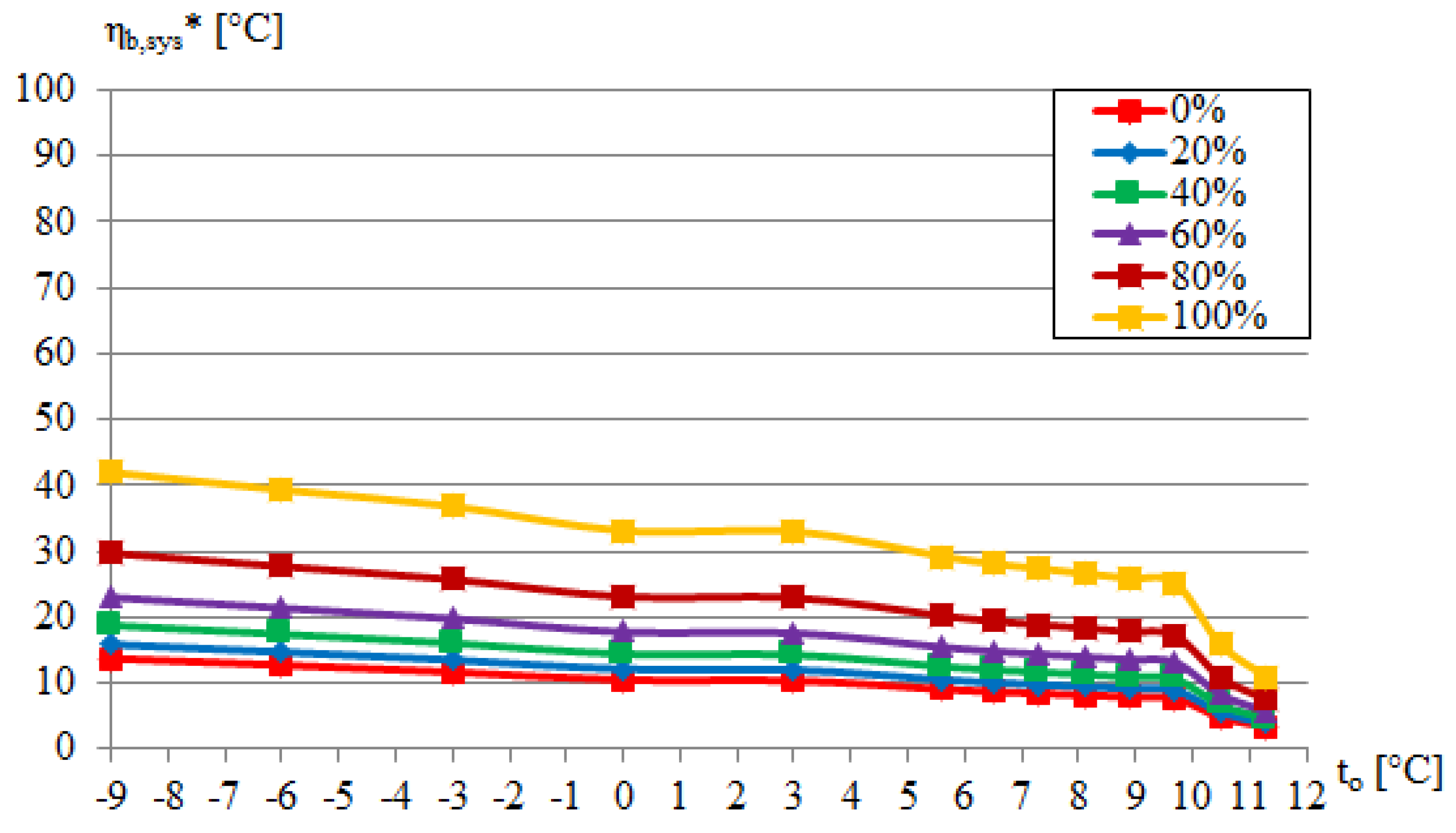
7.2. Solution 1—Part of the Electricity Demand Covered by a Renewable Energy Source

System exergy efficiency is independent of the method of electricity production. The efficiency is the ratio between the useable exergy and the driving exergy regardless of its source. However, the driving exergy source has an impact on the primary exergy efficiency. The first proposed concept is to cover a part of the electricity demand by a renewable energy source, for example, PV panels. Figure 7 presents the dependence between the primary exergy efficiency of the heat pump system and the percentage of electricity demand covered by a renewable energy source. Solution 1 has a great positive impact on the primary exergy efficiency of the heat pump. Moreover, the larger the contribution of the renewable energy source, the greater the impact, which is visible in Figure 7. When the entire electricity demand is covered by a renewable energy source, the primary exergy efficiency reaches the value of the system exergy efficiency.

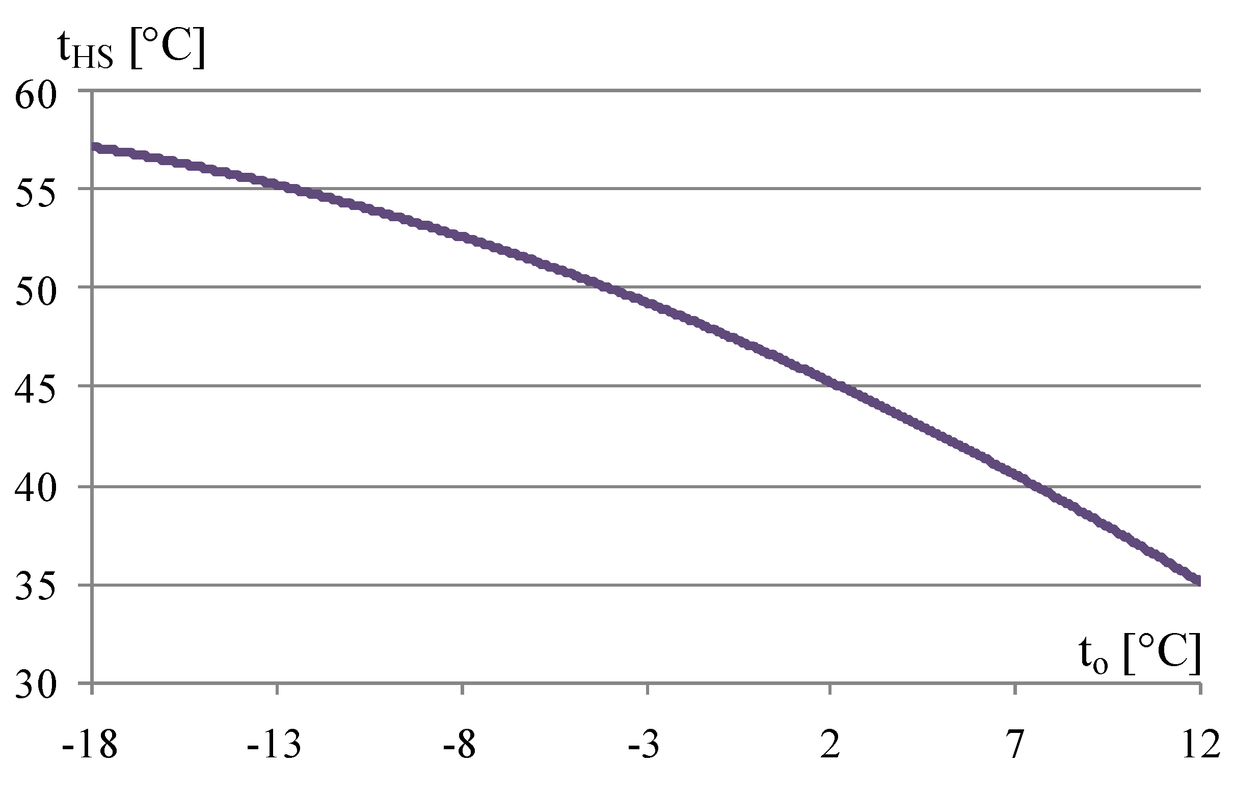
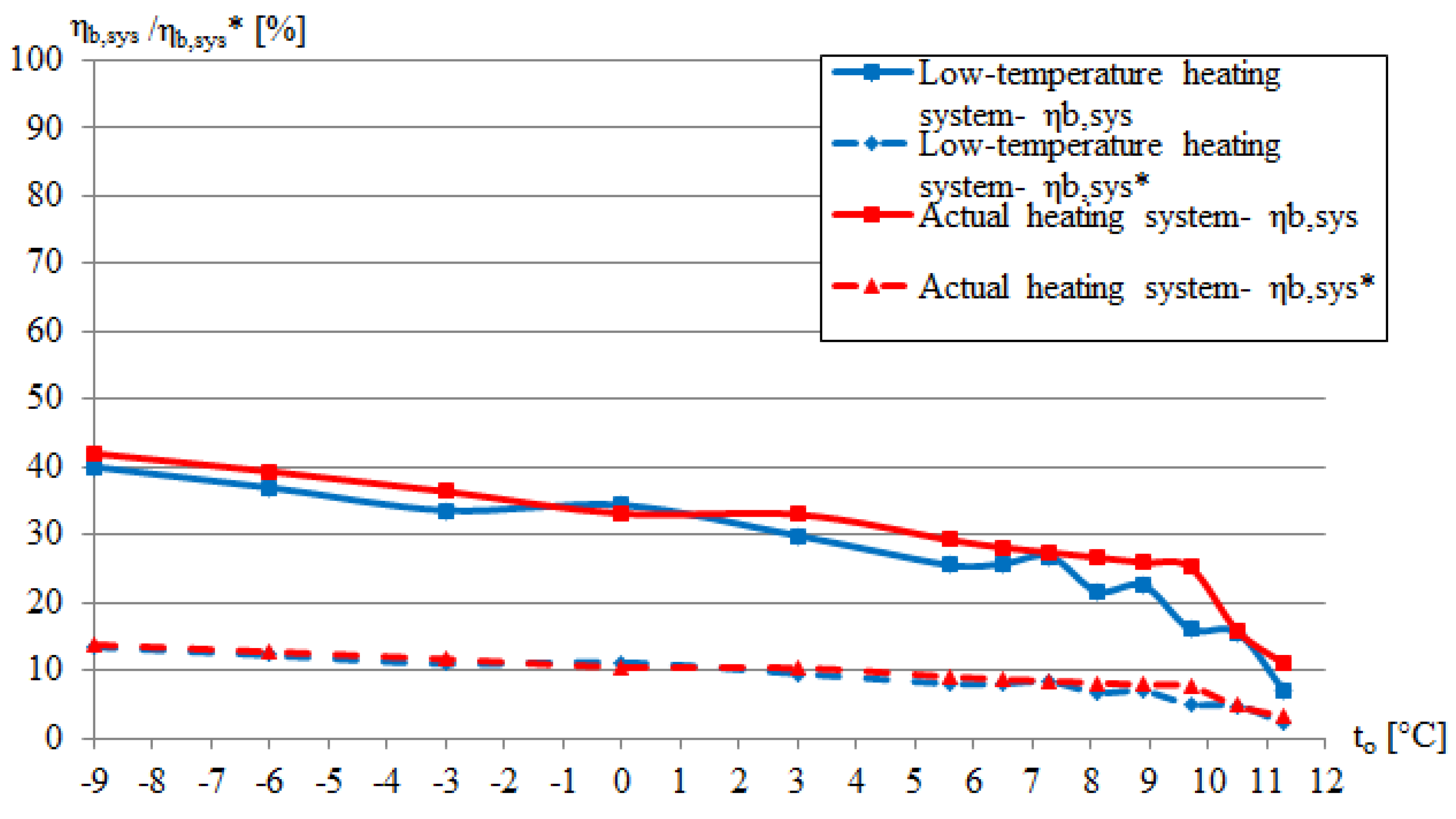
7.3. Solution 2-Low-Temperature Emission System for Heating

The second proposition is to apply a low-temperature emission system for heating. Figure 8 presents the dependence between the temperature of the heating water supplying the heating system and the outdoor temperature for the low-temperature emission system. Application of the low-temperature emission system allows rising the heat pumps efficiency expressed as COP. Therefore, this solution allows for decreasing electricity consumption by 25%. However, it does not affect the exergy performance, which is shown in Figure 9. This is due to a fall in the heating water exergy which is caused by the reduced temperature difference between the heating water and the environment. The decrease of the driving exergy is balanced by the fall in the useable exergy, so the exergy efficiency remains almost the same. Solution 2 allows decreasing energy consumption of the system significantly. Nevertheless, it does not improve the exergy efficiency.

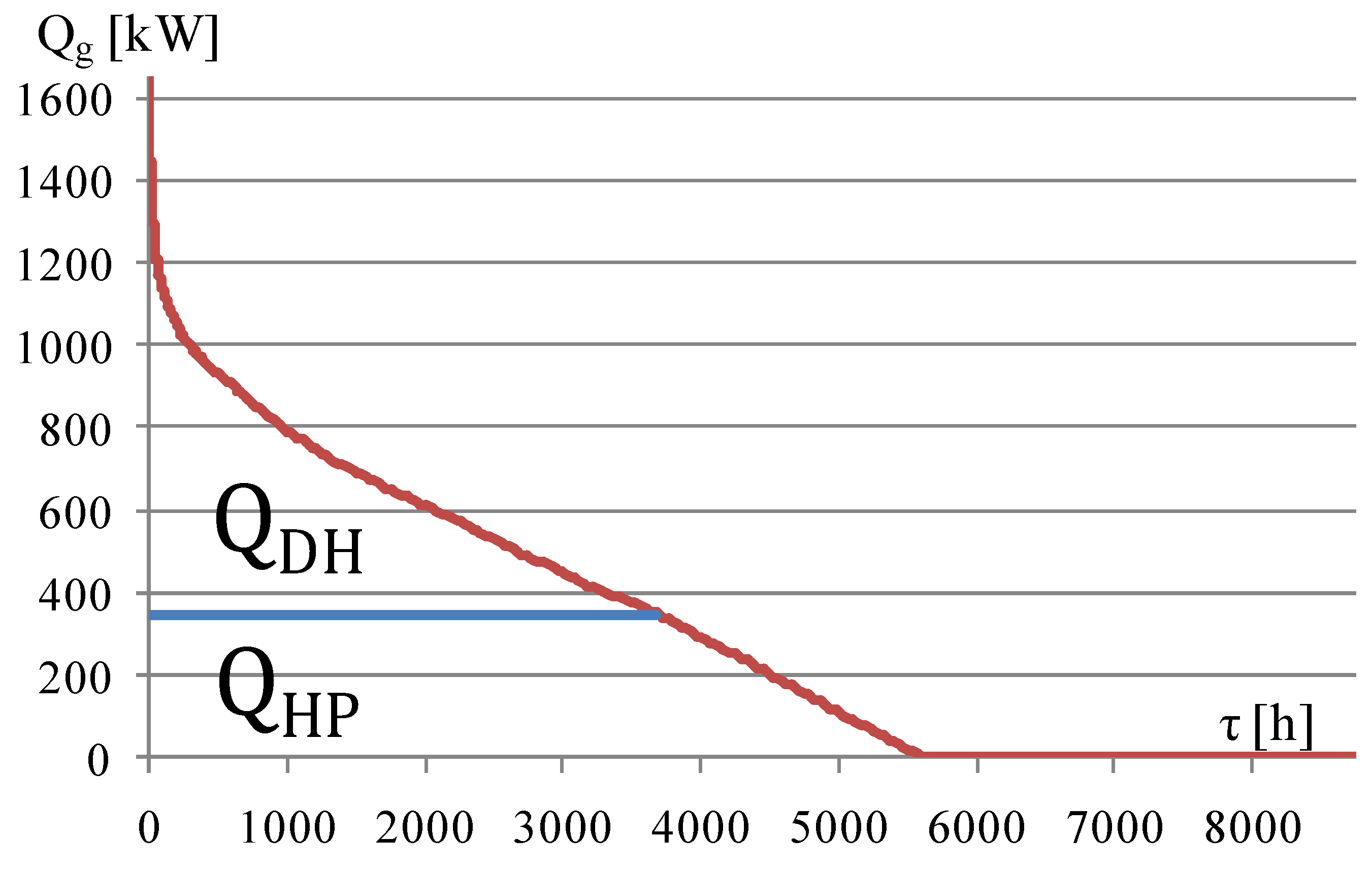
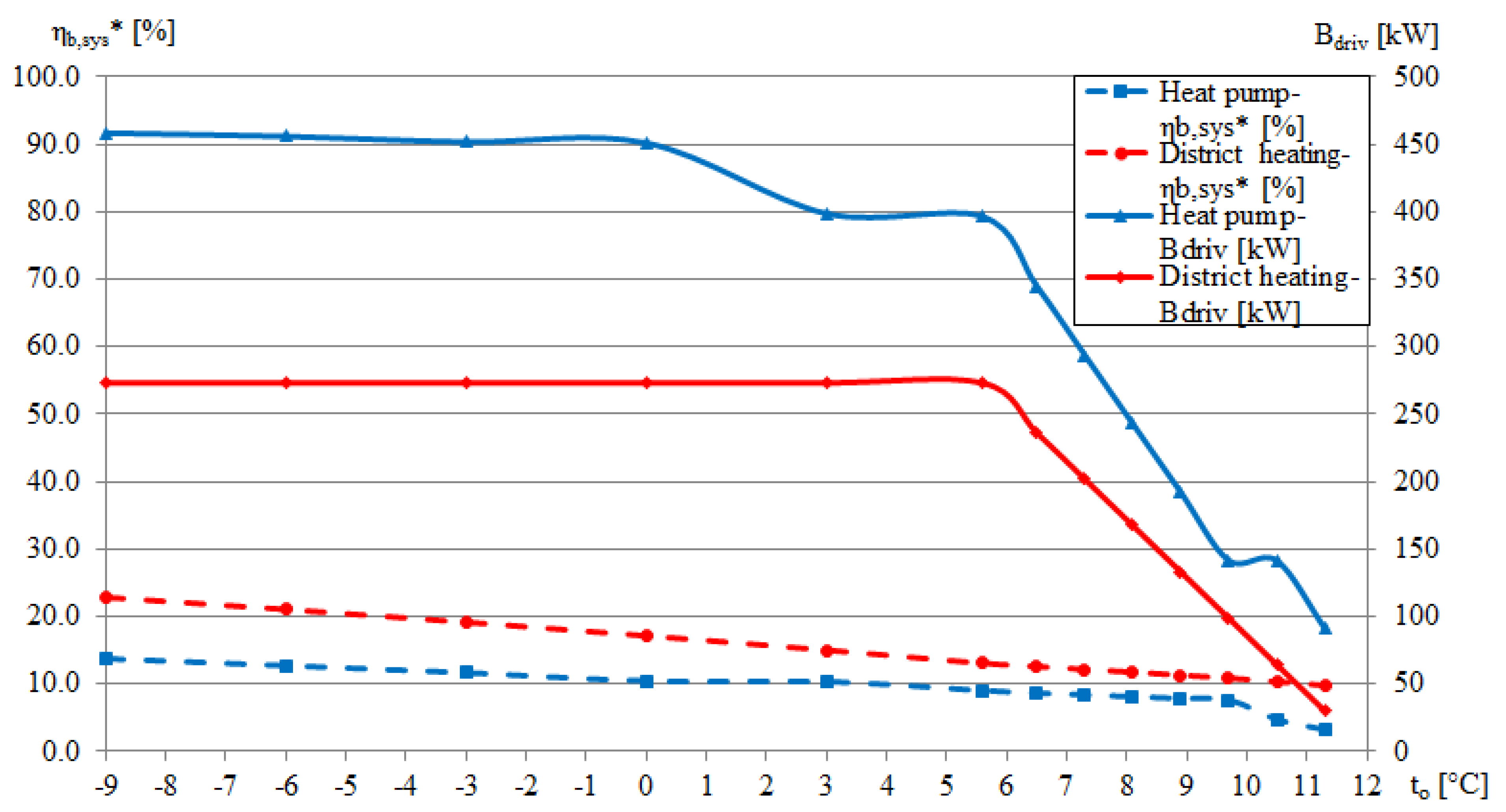
7.4. Solution 3—Heat Pump Replaced by a Heat Exchanger Connected to a District Heating Network Supplied from an Energy-Efficient CHP Plant

The third idea is to apply a district heating network supplied from energy efficient CHP plant as the heat source to replace the heat pump. The primary energy efficiency was calculated as the ratio between the useable exergy and the driving exergy. In the case of the CHP plant, the avoided cost principle has to be taken into consideration [23]. The driving exergy was calculated with the Equations (11)–(15). The useable exergy value was calculated by Equation (8).
e = N el Q ˙ H
N el = e · Q ˙ H
H ˙ F , ch CHP = Q ˙ H + N el η CHP
H ˙ F , ch heat = H ˙ F , ch CHP N el η P
B ˙ driv = B ˙ F , ch heat = β · H ˙ F , ch heat
where
  • e Annual co-generation factor, 0.3 (as for typical coal-fired CHP plant in Poland)
  • N el Electrical power produced in the CHP plant in co-generation with heat, (W)
  • Q ˙ H Heat flux produced in the CHP plant in co-generation with electricity, (W)
  • H ˙ F , ch CHP Total driving energy required for the CHP plant operation, (W)
  • η CHP Energy efficiency of the CHP plant, 0.80
  • H ˙ F , ch heat Driving energy used for the heat production in the CHP plant, (W)
  • η P Energy efficiency of the electricity production and distribution system, 0.33
  • B ˙ F , ch heat Driving exergy used for the heat production in the CHP plant, (W)
  • β Ratio between specific chemical exergy of the fuel used in CHP plant and its low heating value, 1.09
Figure 10 presents a comparison of the primary exergy efficiencies of the system with heat pumps and of the system with the heat exchanger connected to the district heating network. In the analyzed outdoor temperature range, the system with heat exchanger achieves on average 1.7 times higher primary exergy efficiency in comparison to the heat pump. Nevertheless, as in the case of the heat pump, the primary exergy efficiency of the system with the heat exchanger decreases with an increase in the outdoor temperature. This is due to a fall in the temperature difference between the heating water and the surrounding environment. The primary exergy efficiency of the system with the heat exchanger is higher because the driving exergy is much lower, which is visible in Figure 10. The lower driving exergy value is a result of higher energy efficiency of the heat production and distribution compared to the efficiency of electricity production and distribution. The difference between the primary exergy efficiency of the system with the heat pump and the system with the heat exchanger falls with the rise in the outdoor temperature. This is caused by an increase in the energy efficiency of the heat pump due to a decrease in the heating water temperature.

8. Conclusions

The paper presents exergy analysis of a heat supply system with vapor compression heat pumps. The analysis regarding a vertical-bore, ground-source heat pump was performed. The heat pump system is installed in an educational building located on the campus of Poznan University of Technology, Poznan, Poland. The purpose of the research was to evaluate the system from the exergy point of view and to indicate some solutions that allow rising system exergy efficiency and primary exergy efficiency of the system. The analysis confirmed that heating systems are dissipative. It means that the entire driving exergy is used to cover the internal and external exergy losses. In the performed analysis, effects of seasonal thermal load variations on the performance of the system were investigated. The flux of exergy losses generally decrease with an increase in the outdoor temperature. The most significant exergy losses occur in the heat pumps’ compressors due to electricity consumption.
Three solutions that allow increasing the primary exergy efficiency of the heat supply system were proposed. Solution 1 is to cover a part of the electricity demand by a renewable energy source. This solution has a great impact on the primary exergy efficiency of the heat pump system. Moreover, the larger the contribution of the renewable energy source, the greater the impact. Solution 2 is to apply a low-temperature emission system for heating. This solution allows for decreasing energy consumption of the system. However, it does not affect the exergy efficiency. Solution 3 is to apply district heating network as the heat source instead of the heat pump. This solution enables an increase in the primary exergy efficiency of the system on average 1.7 times.
The most efficient way to increase the primary exergy efficiency of the heat supply system, is to power the system by electricity generated from renewable energy sources.
Heat pumps are considered as sustainable solutions for heating because they utilize the heat of the surrounding environment. From an energetic point of view, heat pumps application is an effective solution. However, from the exergetic point of view, heat pumps efficiency is low because they consume electricity, that is a high-quality energy form and generate a low-quality heat.
The exergy analysis of heating systems may contribute to a more rational use of natural resources and to a limitation of high-quality energy consumption. Application of the exergy analysis for the heat supply system with vapor compression heat pumps installed in one of educational buildings of Poznan University of Technology, Poland has proved, that heat pumps are not always the optimal choice of a heat supply.

Author Contributions

Conceptualization, T.M., Methodology, A.R. and T.M.; Software, A.R.; Validation, A.R. and T.M.; Formal Analysis, A.R.; Investigation, A.R. and T.M.; Resources, A.R.; Data Curation, A.R.; Writing-Original Draft Preparation, A.R. and T.M.; Writing-Review and Editing, A.R.; Visualization, A.R.; Supervision, T.M.; Project Administration, T.M.; Funding Acquisition, T.M.

Funding

This research received no external funding.

Acknowledgments

Authors acknowledge administrative and technical support given by Institute of Environmental Engineering Poznan University of Technology.

Conflicts of Interest

The authors declare no conflict of interest.

Nomenclature

B ˙ Exergy flux, (W)
c Specific heat, (J/(kgK))
e Annual co-generation factor, (-)
h Specific enthalpy, (J/kg)
m ˙ Mass flow, (kg/s)
N Electrical power, (W)
Q Heat, (J)
s Specific entropy, (J/kgK)
t Temperature, (°C)
T Temperature, (K)
β P Ratio between specific chemical exergy of the fuel used in electricity production and its low heating value, (-)
δ Loss, (-)
Δ Change, (-)
η Efficiency, (%)
τ Time, (h)
Indices
COMP Compressor
COND Condenser
CP Circulating pump
DH District heating
driv Driving
em Electro-mechanical
EVAP Evaporator
ext External
ExV Expansion valve
G Ground
H High-temperature
HP Heat pump
HS Heat source
i Internal
in Entering
L Low-temperature
M Mixing
o Reference
out Leaving
P Electricity production
R Return
S Supply
sys System
use Useable
w Water
WG Glycol
* Primary

References

  1. Schmidt, D. Low exergy systems for high-performance buildings and communities. Energy Build. 2009, 41, 331–336. [Google Scholar] [CrossRef]
  2. Cakir, U.; Comakli, K. Exergetic interrelation between an heat pump and components. Appl. Therm. Eng. 2016, 105, 659–668. [Google Scholar] [CrossRef]
  3. Li, R.; Ooka, R.; Shukuya, M. Theoretical analysis on ground source heat pump and air source heat pump systems by the concepts of cool and warm exergy. Energy Build. 2014, 75, 447–455. [Google Scholar] [CrossRef]
  4. Esen, H.; Inalli, M.; Esen, M.; Pihtili, K. Energy and exergy analysis of a ground-coupled heat pump system with two horizontal ground heat exchangers. Build. Environ. 2007, 42, 3606–3615. [Google Scholar] [CrossRef]
  5. Verda, V.; Cosentino, S.; Lo Russo, S.; Sciacovelli, A. Second law analysis of horizontal geothermal heat pump systems. Energy Build. 2016, 124, 236–240. [Google Scholar] [CrossRef] [Green Version]
  6. Habtamu, M.B.; Torger, B.; Bye, P.F.; Erlend, A. Parametric study of a vertically configured ground source heat pump system. Energy Procedia 2017, 111, 1040–1049. [Google Scholar] [CrossRef]
  7. Abbasi, Y.; Baniasadi, E.; Ahmadikia, H. Performance Assessment of a Hybrid Solar-Geothermal Air Conditioning System for Residential Application: Energy, Exergy, and Sustainability Analysis. Int. J. Chem. Eng. 2016, 2016, 1–13. [Google Scholar] [CrossRef]
  8. Hu, P.; Hu, Q.; Lin, Y.; Yang, W.; Xing, L. Energy and exergy analysis of a ground source heat pump system for a public building in Wuhan, China under different control strategies. Energy Build. 2017, 152, 301–312. [Google Scholar] [CrossRef]
  9. Menberg, K.; Heo, Y.; Choi, W.; Ooka, R.; Choudhary, R.; Shukuya, M. Exergy analysis of a hybrid ground-source heat pump system. Appl. Energy 2017, 204, 31–46. [Google Scholar] [CrossRef]
  10. Ozgener, O.; Hepbasli, A. Modeling and performance evaluation of ground source (geothermal) heat pump systems. Energy Build. 2007, 39, 66–75. [Google Scholar] [CrossRef]
  11. Cho, H. Comparative study on the performance and exergy efficiency of a solar hybrid heat pump using R22 and R744. Energy 2015, 93, 1267–1276. [Google Scholar] [CrossRef]
  12. Bi, Y.; Wang, X.; Liu, Y.; Zhang, H.; Chen, L. Comprehensive exergy analysis of a ground-source heat pump system for both building heating and cooling modes. Appl. Energy 2009, 86, 2560–2565. [Google Scholar] [CrossRef]
  13. Hepbasli, A. Exergetic modeling and assessment of solar assisted domestic hot water tank integrated ground-source heat pump systems for residences. Energy Build. 2007, 39, 1211–1217. [Google Scholar] [CrossRef]
  14. Saloux, E.; Sorin, M.; Teyssedou, A. Modeling the exergy performance of heat pump systems without using refrigerant thermodynamic properties. Energy Build. 2016, 112, 69–79. [Google Scholar] [CrossRef]
  15. Stanek, W.; Simla, T.; Gazda, W. Exergetic and thermo-ecological assessment of heat pump supported by electricity from renewable sources. Renew. Energy 2019, 131, 404–412. [Google Scholar] [CrossRef]
  16. Mróz, T.M. Energy Management in Built Environment—Tools and Evaluation Procedures; Publishing House of Poznań University of Technology: Poznań, Poland, 2013; ISBN 978-83-7775-238-8. [Google Scholar]
  17. Szargut, J. Sequence method of determination of partial exergy losses in thermal systems. Exergy Int. J. 2001, 1, 85–90. [Google Scholar] [CrossRef]
  18. Szargut, J. Exergy. Calculation and Application Handbook; Wydawnictwo Politechniki Śląskiej: Gliwice, Poland, 2007; ISBN 978-83-7335-438-8. [Google Scholar]
  19. PN-76/B-03420—Wentylacja i Klimatyzacja. Parametry Obliczeniowe Powietrza Zewnętrznego; Polish Committee for Standarization: Warsaw, Poland, 1976. [Google Scholar]
  20. Ministry of Investment and Economic Development. Dane do Obliczeń Energetycznych Budynków. 2018. Available online: https://www.miir.gov.pl/strony/zadania/budownictwo/charakterystyka-energetyczna-budynkow/dane-do-obliczen-energetycznych-budynkow-1/ (accessed on 6 May 2018).
  21. Solkane Refrigerants 8.0. Available online: https://solkane-refrigerants.software.informer.com/8.0/ (accessed on 25 May 2018).
  22. Rozporządzenie Ministra Infrastruktury i Rozwoju w sprawie metodologii wyznaczania świadectw charakterystyki energetycznej budynku lub części budynku oraz świadectw charakterystyki energetycznej; Polish Ministry of Infrastructure and Development: Warsaw, Poland, 27 February 2015.
  23. Mróz, T.M.; Dutka, A. Exergy–economic evaluation of heat recovery device in mechanical ventilation system. Energy Build. 2015, 86, 296–304. [Google Scholar] [CrossRef]
Figure 1. Exergy model of the vapor compression heat pump. Reproduced from [16], publisher: 2013.
Energies 12 01028 g001
Figure 2. Exergy model of the heat supply system with heat pumps.
Energies 12 01028 g002
Figure 3. Dependence between the heating load and the number of hours in one year.
Energies 12 01028 g003
Figure 4. Dependence between the temperature of the heating water supplying the heating system and the outdoor temperature.
Energies 12 01028 g004
Figure 5. Exergy losses of the system components, useable exergy and driving exergy depending on the outdoor temperature.
Energies 12 01028 g005
Figure 6. Exergy efficiency and primary exergy efficiency depending on the outdoor temperature.
Energies 12 01028 g006
Figure 7. Primary exergy efficiency depending on the contribution of electricity demand covered by a renewable energy source.
Energies 12 01028 g007
Figure 8. Dependence between the temperature of the heating water supplying the heating system and the outdoor temperature for the low-temperature emission system.
Energies 12 01028 g008
Figure 9. System exergy efficiency and primary exergy efficiency of the actual system and the low-temperature system depending on the outdoor temperature.
Energies 12 01028 g009
Figure 10. Primary exergy efficiency and driving exergy for the system with heat pump and of the system with a heat exchanger connected to the district heating network.
Energies 12 01028 g010
Table 1. Exergy balance equations of the heat pump components.
CompressorCondenser
B ˙ in = B ˙ out + δ B ˙ COMP
B ˙ in = N COMP + B ˙ 1
B ˙ out = B ˙ 2
δ B ˙ COMP = B ˙ 1 + N COMP B ˙ 2
δ B ˙ COMP =   m ˙   · ( h 1 h 2 T o · ( s 1 s 2 ) ) + N COMP
N COMP = N COMP , i η COMP , em
B ˙ in = B ˙ out + δ B ˙ COND
B ˙ in = B ˙ 2 + B ˙ w , 1
B ˙ out = B ˙ 3 + B ˙ w , 2
δ B ˙ COND = B ˙ 2 B ˙ 3 + B ˙ w , 1 B ˙ w , 2
δ B ˙ COND =   m ˙   · ( h 2 h 3 T o · ( s 2 s 3 ) )
+ m ˙ w · c w · ( T w , 1 T w , 2 T o · ln T w , 1 T w , 2 )
Expansion ValveEvaporator
B ˙ in = B ˙ out + δ B ˙ ExV
B ˙ in = B ˙ 3
B ˙ out = B ˙ 4
δ B ˙ ExV = B ˙ 3 B ˙ 4
δ B ˙ ExV =   m ˙   · ( h 3 h 4 T o · ( s 3 s 4 ) )
B ˙ in + Δ B ˙ HS = B ˙ out + δ B ˙ EVAP
B ˙ in = B ˙ 4
B ˙ out = B ˙ 1
δ B ˙ EVAP = B ˙ 4 B ˙ 1 + Δ B ˙ HS
δ B ˙ EVAP =   m ˙   · ( h 4 h 1 T o · ( s 4 s 1 ) ) + ( 1 T o T g ) · Q ˙ o
Table 2. Main devices list and their design characteristics.
DeviceQuantityDesign Characteristics
Heat Pump Unit2Heating capacity: 175 kW, Input power: 60.8 kW, 4 compressors on/off mode
Primary circuit circulation pump1Flow rate: 89.5 m3/h, Input power: 11.1 kW, Constant speed
Secondary circuit circulation pump1Flow rate: 32.7 m3/h, Input power: 1.3 kW, Constant speed
Table 3. List of the control volumes and their specification.
Control VolumeName of the System ComponentExergy Entering the CV (W)Exergy Leaving the CV (W)
CV1-HP1Heat pump 1 B ˙ in = N COMP 1 + m ˙ L 1 · c WG ( T LS T 0 T 0 · ln T LS T 0 ) + m ˙ H 1 · c W ( T HR T 0 T 0 · ln T HR T 0 ) B ˙ out = m ˙ L 1 · c WG ( T LR 1 T 0 T 0 · ln T LR 1 T 0 ) + m ˙ H 1 · c W ( T HS 1 T 0 T 0 · ln T HS 1 T 0 )
CV2-HP2Heat pump 2 B ˙ in = N COMP 2 + m ˙ L 2 · c WG ( T LS T 0 T 0 · ln T LS T 0 ) + m ˙ H 2 · c W ( T HR T 0 T 0 · ln T HR T 0 ) B ˙ out = m ˙ L 2 · c WG ( T LR 2 T 0 T 0 · ln T LR 2 T 0 ) + m ˙ H 2 · c W ( T HS 2 T 0 T 0 · ln T HS 2 T 0 )
CV3-M1Mixing of heating water supplying the heating system B ˙ in = m ˙ H 1 · c W ( T HS 1 T 0 T 0 · ln T HS 1 T 0 ) + m ˙ H 2 · c W ( T HS 2 T 0 T 0 · ln T HS 2 T 0 ) B ˙ out = m ˙ H · c W ( T HS T 0 T 0 · ln T HS T 0 )
CV4-M2Mixing of the heat transfer medium returning to the heat source B ˙ in = m ˙ L 1 · c WG ( T LR 1 T 0 T 0 · ln T LR 1 T 0 ) + m ˙ L 2 · c WG ( T LR 2 T 0 T 0 · ln T LR 2 T 0 ) B ˙ out = m ˙ L · c WG ( T LR T 0 T 0 · ln T LR T 0 )
CV5-L,CPCirculating pump in the primary circuit B ˙ in = N L , CP + m ˙ L · c WG ( T LR T 0 T 0 · ln T LR T 0 ) B ˙ out = m ˙ L · c WG ( T LR T 0 T 0 · ln T LR T 0 )
CV6-H,CPCirculating pump in the secondary circuit B ˙ in = N H , CP + m ˙ H · c W ( T HS T 0 T 0 · ln T HS T 0 ) B ˙ out = m ˙ H · c W ( T HS T 0 T 0 · ln T HS T 0 )
CV7-HSGround heat exchanger B ˙ in = Q ˙ L + m ˙ L · c WG ( T LR T 0 T 0 · ln T LR T 0 )
Q ˙ L = Δ B ˙ HS = m ˙ L · c WG ( T LS T LR ) · ( T G T 0 T G )
B ˙ out = m ˙ L · c WG ( T LS T 0 T 0 · ln T LS T 0 )
Table 4. Data for calculations.
Outdoor TemperatureTotal Heating LoadHeating Power of the Heat PumpsCoefficient of PerformancePower of the Compressors Working in the HP1Power of the Compressors Working in the HP2Temperature of the Heat Transfer Medium Entering the EvaporatorTemperature of the Heat Transfer Medium Leaving the Circulation PumpHeat Exchanged with the Heat Source (Ground)Temperature of the Heating Water Leaving the Circulating PumpTemperature of the Heating Water Entering the Condenser
to (°C)Qg (kW)QH (kW)COP (-)NCOMP1 (kW)NCOMP2 (kW)tLS (°C)tLR (°C)QL (kW)tHS’ (°C)tHR (°C)
−91155.6350.02.5260.860.85.83.12230.553.344.1
−6990.5350.02.6860.860.85.93.22230.551.542.3
−3825.4350.02.8760.860.86.23.50230.549.440.2
0660.3350.03.1260.860.86.73.96230.547.037.8
3495.2350.03.4360.845.67.34.43244.144.435.2
5.6352.2350.03.7860.845.68.05.13244.142.032.8
6.5302.6302.63.9345.645.68.35.80210.541.133.1
7.3258.6258.64.0545.630.48.56.42180.140.333.5
8.1214.6214.64.2230.430.48.87.05149.839.533.8
8.9170.6170.64.3730.415.29.17.69119.438.634.1
9.7126.6126.64.5515.215.29.48.3489.137.734.4
10.582.582.54.7415.215.29.79.1745.136.934.7
11.338.538.54.9515.2010.09.814.736.034.9
Table 5. Exergy losses in the system components.
Outdoor TemperatureHeat Pump 1Heat Pump 2Mixing 1Mixing 2Circulating Pump in the Primary CircuitGround Heat ExchangerCirculating Pump in the Secondary Circuit
to (°C)δBHP1 (W)δBHP2 (W)δBM1 (W)δBM2 (W)δBL,CP (W)δBHS (W)δBH,CP (W)
−9.035,241.835,241.8206.50.010,668.44278.71117.5
−6.036,448.436,448.4191.50.010,774.84248.21132.5
−3.037,878.037,878.0175.70.010,874.64070.91148.3
0.039,541.939,541.9158.90.010,967.73742.71165.1
3.038,250.229,404.5231.127.911,059.93524.01182.8
5.640,317.530,969.7217.128.111,129.12947.11199.1
6.530,858.430,858.4119.10.011,137.42193.41204.9
7.330,444.320,825.8214.230.711,144.01602.01210.2
8.120,449.620,449.6108.50.011,150.21096.01215.5
8.919,805.410,230.3226.439.411,155.8679.81220.9
9.79643.39643.397.60.011,161.0357.81226.4
10.511,712.711,712.792.00.011,159.890.31232.0
11.311,988.50.0144.313.011,164.03.41237.7

