Article

Stabilization Method Considering Disturbance Mitigation for DC Microgrids with Constant Power Loads

1
Hunan Institute of Engineering, Xiangtan 411104, China
2
School of Automation, Central South University, Changsha 410083, China
3
No. 3 Middle School of CiLi, Zhangjiajie 427200, China
*
Author to whom correspondence should be addressed.
Energies 2019, 12(5), 873; https://doi.org/10.3390/en12050873
Submission received: 23 January 2019 / Revised: 27 February 2019 / Accepted: 2 March 2019 / Published: 6 March 2019
(This article belongs to the Special Issue Interfacing of Power Electronics in Converter Dominated Grids)

Abstract

:
In this paper, the stability of direct current (DC) microgrids with a constant power load (CPL) and a non-ideal source is investigated. The CPL’s negative impedance will destabilize the system, and disturbances in the non-ideal source will degrade the load voltage quality. In this study, we aim to: (1) overcome the instability of the CPL; (2) mitigate disturbances from the non-ideal source; (3) prevent the discontinuous harmonic current of high-frequency switching regulator from interfering with the source. Then, a stabilization method based on active damping which can achieve the above three objectives simultaneously is proposed. To obtain the stability conditions, the small-signal model of the system near the high-voltage equilibrium is established. Then, stability conditions are derived by eigenvalue analysis, and the domain of attraction near equilibrium is also obtained using the quadratic Lyapunov function. For the second objective, the key is to choose the optimal parameters to achieve disturbance attenuation. For the third objective, the active damper can separate the source from the switching regulator, which can prevent the discontinuous harmonic current. Moreover, the proposed method can be extended to multiple cases, and simulation results verify the effectiveness of the proposed method.

1. Introduction

Microgrids, which primarily rely on renewable energy such as photovoltaic (PV) and wind power, have been identified as an effective complement to traditional power systems [1,2,3]. Usually, they can be worked in two modes: grid-connected mode, and islanded mode. Usually, the main control objectives of a DC microgrid include maintaining stability [4,5,6,7,8,9], minimizing cost [10,11,12], sharing power and regulating voltage [13]. For these objectives, there are mainly three control methods: decentralized control [10,12,14,15,16,17], distributed control [18,19,20,21,22,23,24,25,26] and centralized control [11,27].
In general, there are two kinds of microgrids: direct current (DC) microgrids and alternating current (AC) microgrids. At present, domestic research on microgrids has primarily focused on AC microgrids [12,13,14,15,16,17]. However, DC microgrids have the following advantages: high transmission efficiency, high reliability, no frequency synchronization issues, easier integration of renewable energy, and ease of stabilization, therefore, DC microgrids are increasingly being used in applications such as aircraft, spacecraft, and electric vehicles [4,24].
In DC microgrids, the load is typically connected to the DC bus through a DC/DC or DC/AC converter. When the response of the load-end converter is rapid, the load exhibits a negative impedance, which is equivalent to a constant power load (CPL) [4]. To ensure stable and reliable operation of a DC microgrid, voltage stability is essential. To address this issue, numerous studies have been performed to evaluate modeling, stability analysis, and control strategies [28,29,30,31,32,33,34,35,36,37,38,39,40,41,42,43,44,45,46,47,48,49]. These studies can be categorized as two groups based on the number of distributed generation units: 1) one DG unit and one CPL; 2) n DG units and m CPLs.
The first category focuses only on stability analysis and stabilization methods for a single converter with one CPL [28,29,30,31,32,33,34,35,36,37,38,39,40,41,42,43,44]. Several linear stabilization methods have been used to stabilize such systems. Because voltage oscillations can be mitigated by increasing damping and reducing negative impedance, methods based on the addition of resistive loads, filters, and energy storage have been proposed [28]. Moreover, several linear stabilization methods have also been proposed, such as passivity-based control strategy [29,30], active damping method [31,32,33], and virtual impedance method [34,35]. To fulfill small-signal stability conditions, some impedance-based stability criteria have been proposed [34,36]. To analyze the large-signal stability of a system, several Lyapunov function-based methods have been proposed, including the Lure Lyapunov function [37], Brayton-Moser’s mixed potential [38,39,40], and the Popov criterion [41]. To ensure that the system is globally asymptotically stable, novel nonlinear techniques based on feedback linearization have been introduced, which transform an unstable nonlinear system into a stable linear system [42,43]. Meanwhile, nonlinear stabilization methods based on sliding modes have been investigated [5,44]. Comparative speaking, the linear stabilization methods such as PBC, virtual RLC damper are simple, easy and effective, but the equilibrium is not global asymptotically stable (GAS); the nonlinear controller such as feedback linearization and sliding mode control can achieve GAS, but it is more complicated and may need communication in some occasions [45].
The second group extends the stability analysis to a system with n converters [45,46,47,48,49]. The structures of DC microgrids with multiple DG units can be divided into two types: single bus and multiple bus. For a DC microgrid with a single-bus structure, the loads throughout the entire bus are equivalent to a common load when the resistance of the DC bus can be neglected. The topology of this type of DC microgrid is equivalent to the star type. Likewise, the topology of a DC microgrid with multiple DG units is meshed. The stability of a DC microgrid with star topology under droop control was analyzed in [45,46,47]. To simplify this problem, a reduced-order linearized model was derived, and transient processes were ignored [46]. Another stability condition has been derived by assuming that all DG units have the same ratio between inductance and resistance [47]. These studies show that the system is stable if the droop coefficient is larger than the equivalent negative impedance of CPL. To study the exact behavior of a CPL in a parallel multi-converter system, a high-dimensional model is estabilished to analyze system stability. Using results for quadratic eigenvalue problems, a more accurate stability condition has been obtained [45]. The stability of a star-type DC microgrid with distributed control has been analyzed in [48], and analytical stability conditions were established as a function of the system parameters by using the inertia theorem. The stability of a meshed DC microgrid with multiple buses has been analyzed in [49]. Based on Tarski’s fixed-point theorem, the existence conditions for a system equilibrium were obtained. Moreover, stability conditions ensuring that the system allows a robust stable equilibrium were obtained [49].
In the above studies, the DG units are modeled as ideal controlled voltage sources (CVSs) or CVSs with DC/DC converters. However, in a DC microgrid, DG units are primarily renewable energy sources with bounded uncertain disturbances. To our best knowledge, the stability and disturbances attenuation of the DC microgrid with a CPL and non-ideal sources has hardly been considered. Moreover, the discontinuous harmonic current produced by the high-frequency switching of the DC/DC converter will damage the source. This issue should also be considered. In this paper, an active damping method is proposes to overcome the CPL’s instability, mitigate disturbances in the DG and prevent the discontinuous harmonic current simultaneously. The main contributions of this paper can be summarized as follows:
First, a stabilization method based on active damping, which can overcomes the CPL’s instability and mitigates disturbances in non-ideal sources, is proposed. Moreover, the active damper can also protect the source input from the influence of a discontinuous harmonic current produced by high-frequency switching.
Second, the stability of the system under the proposed stabilization control strategy is analyzed, and a small-signal stability condition is obtained based on the Routh-Hurwitz criterion. This paper shows that the stability criterion derived in [40] is incorrect from two aspects of theoretical analysis and simulation. Moreover, an approach based on the quadratic Lyapunov function is developed to analyze the large-signal stability and to estimate the domain of attraction (DOA) at equilibrium.
Finally, this paper extends the proposed stabilization method to a system with multiple paralleled DC/DC converters. Further, it demonstrates that the dynamic model of a system with multiple identical converters can be reduced to a model with a single converter. The stability of the system with multiple non-identical converters is also investigated in simulation, and the simulation results shows that the proposed method can also be applicable.
This paper is organized as follows: Section 2 introduces the topologies and the proposed stabilization technique for a DC microgrid. Section 3 provides a stability analysis of a DC microgrid under the proposed control. Section 4 presents a generalization of the proposed stabilization method. Section 5 provides case studies and simulations, and the conclusions are drawn in Section 6.

2. Problem Formulation and Stabilization Method

2.1. Problem Formulation

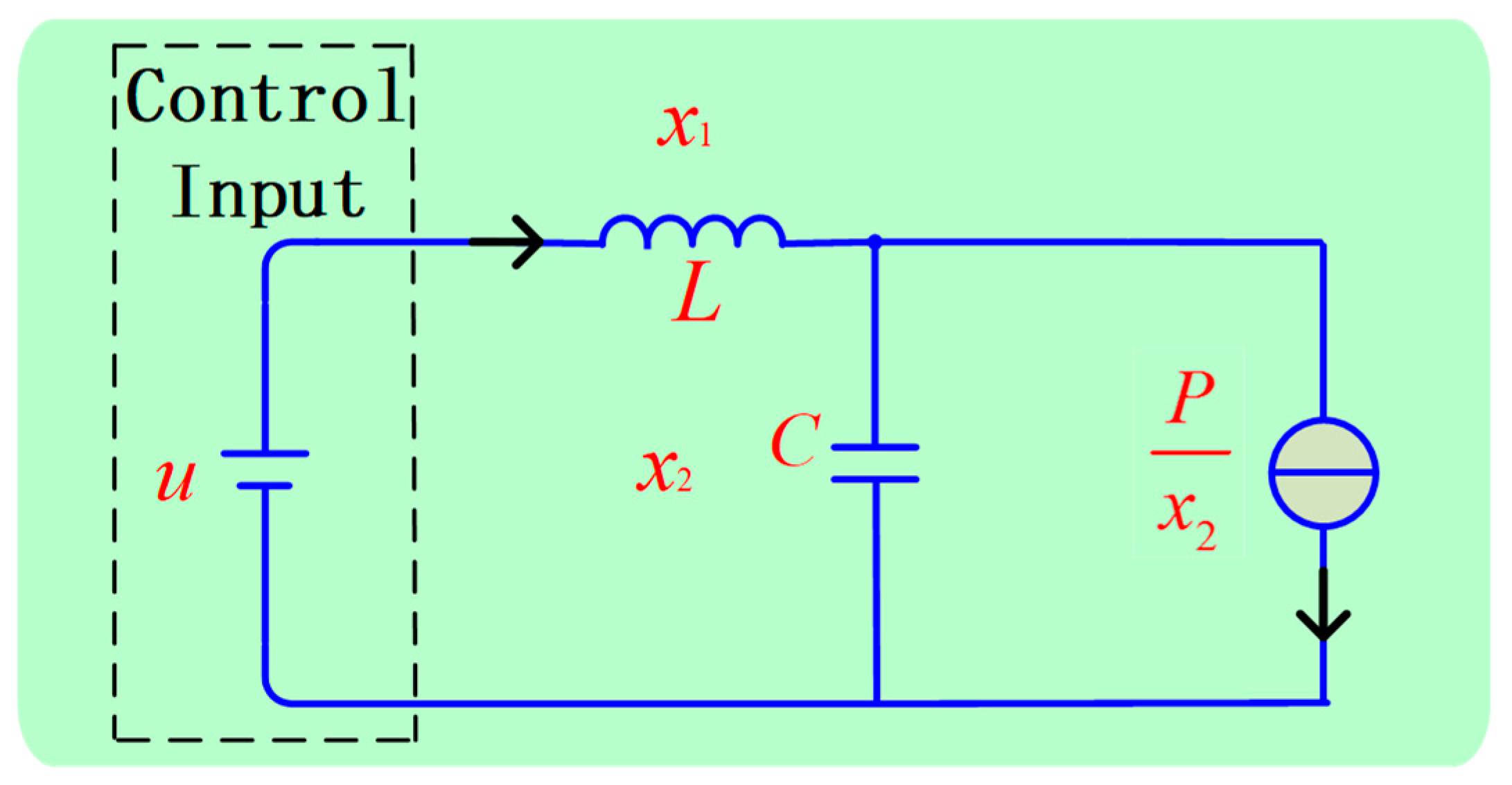
A DC microgrid, whose simplified model is presented in Figure 1, is composed of a load, a DC/DC converter, and an energy input. In most previous studies, the energy input is assumed as a constant voltage source. In general, the load is connected to the DC bus through a converter to regulate the voltage. When the response of the load converter is rapid, the load can be treated as an ideal CPL. An equivalent average model is presented in Figure 2. Here, a large-signal model of the CPL is given as a controlled current source whose output current is equal to the constant power divided by the voltage. The energy input and the switch are equivalent to a CVS, which is the control input of the system. According to [45], the state equations of the system in figure are given by:
{ L d x 1 d t = u x 2 C d x 2 d t = x 1 P x 2
where L, C, x1, x2, P, and u are the inductance, capacitance, inductance current, output voltage, CPL, and control input, respectively.

2.2. Proposed Stabilization Method

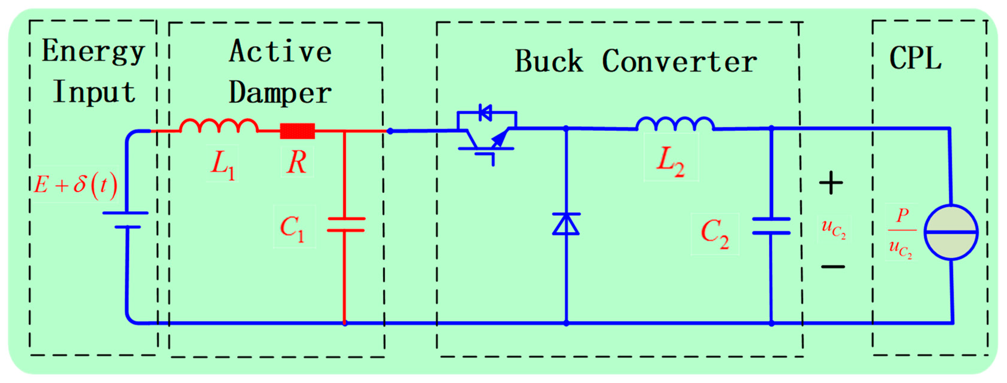
The mechanism by which the CPL leads to voltage instability has been explained in [28], and numerous stabilization methods based on the system in (1) have been proposed [28,29,30,31,32,33,34,35,36,37,38,39,40,41,42,43,44,45,46]. However, the following two important issues have not been considered in these studies. First, when the energy input comes from a renewable energy source, disturbances in the input will cause output voltage fluctuations, which will reduce the quality of the power supply. Second, unlike a boost circuit, which has an LC filter between the source and the converter, the source of a Buck circuit can easily experience interference from an insulated gate bipolar transistor (IGBT) with a high switching frequency. The high-frequency switching of an IGBT will produce a discontinuous harmonic current, which degrades the power source. To address these issues, this paper proposes an active damping method, which is presented in Figure 3. Here, R, L1, and C1 are the resistance, inductance, and capacitance of the active damping circuit, respectively, and L2 and C2 are the inductance and capacitance of the filter circuit of the Buck converter, respectively. Term δ ( t ) represents the uncertain disturbance in the energy input, which is time-varying and bounded.
The resistance of the active damper will increase the damping of the system, which can overcome the negative impedance of the CPL. Moreover, the active damper can act as a filter to suppress high-frequency disturbances in the non-ideal input for the Buck converter. The active damper can also isolate the input sources from the IGBT, thereby reducing the high-frequency current harmonics due to the pulse-width modulation (PWM) control operation.
An equivalent average model of the system in Figure 3 is presented in Figure 4. The model can be decomposed into two sub-circuits. Here, x1 and x3 are the currents through L1 and L3, respectively, and x2 and x4 are the voltages across C1 and C2, respectively. The constant d corresponds to the duty cycle, where 0 d 1 .
According to Kirchhoff’s voltage law, the dynamics of the system in Figure 4 can be described by the following differential equations:
{ L 1 d x 1 d t = E + δ ( t ) R x 1 x 2 C 1 d x 2 d t = x 1 d x 3 L 2 d x 3 d t = d x 2 x 4 C 2 d x 4 d t = x 3 P x 4
Let us assume that the maximal value of the disturbance is far less than E. Then, the operation points of the system are determined by:
{ 1 R E x 1 1 E x 2 = δ ( t ) E 0 x 1 d x 3 = 0 d x 2 x 4 = 0 x 3 P x 4 = 0
Solving (3), the operation points ( x 1 , x 2 , x 3 , x 4 ) of the system are obtained as:
{ e 1 = ( E E 2 4 R P 2 R , E + E 2 4 R P 2 , E E 2 4 R P 2 R d , d ( E + E 2 4 R P ) 2 ) e 2 = ( E + E 2 4 R P 2 R , E E 2 4 R P 2 , E + E 2 4 R P 2 R d , d ( E E 2 4 R P ) 2 )
Clearly, the system has two operation points. Operation point e1 has a higher voltage and lower current than e2, which results in a lower line loss for e1. Hence, this paper investigates the stability of the system near e1. We linearize (2) about e1, and the system Jacobian matrix is given by:
J = [ R L 1 1 L 1     1 C 1 0 d C 1     d L 2 0 1 L 2     1 C 2 P C 2 v 2 ]
where v = d ( E + E 2 4 R P ) 2 .
Compared with Equation (1), the system in (2) is a higher-order system in the presence of an active damper, which will increase the difficulty of stability analysis. Next, we analyze the stability of operation point e1 and determine the stability conditions.

3. Stability Analysis

3.1. Recent Related Results

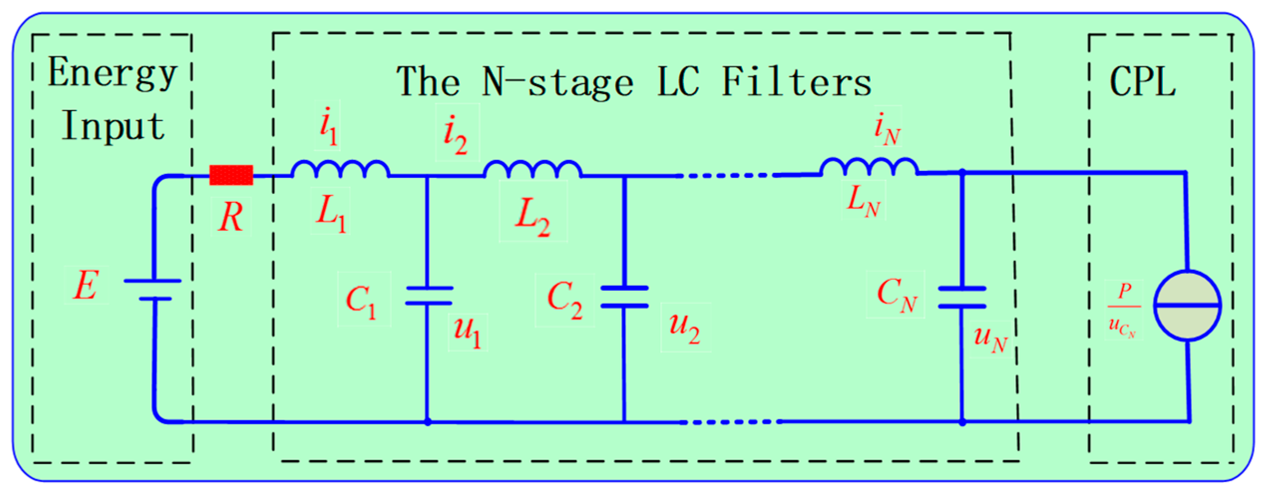
The mixed potential theory developed by Brayton and Moser is generally used to construct Lyapunov-type functions to determine stability criteria for nonlinear electrical networks. In [40], the stability criteria for an electrical system with multistage LC filters (presented in Figure 5) were obtained based on the Brayton–Moser mixed potential theory. In Figure 5, i i and u i denote the inductor current and capacitor voltage of the i-th LC filter, respectively.
According to the Equation (8) in Reference [40], the state equation of the DC microgrid with N-stage LC filters is given by:
{ L 1 d i 1 d t = E R i 1 u 1 C 1 d u 1 d t = i 1 i 2 L 2 d i 2 d t = u 1 u 2 C 2 d u 2 d t = i 2 i 3 L N d i N d t = u N 1 u N C N d u N d t = i N P u N
The main results in [40] can be briefly derived as follows: firstly, according to Equation (9) in [40], the mixed potential function is equivalent to the following expression:
P ( i , v ) = 1 2 R i 1 2 + 0 u N P u N d u N + i T M v i T γ
where i = [ i 1 i 2 i N ] T , u = [ u 1 u 2 u N ] T , γ = [ E 0 0 ] T , and M is given by:
M = [ 1         1 1         1 1                 1 1 ]
Then, according to the Equation (14) in [24], the system in (6) is stable if the following holds:
L α C α P v 2 < R < E 2 4 P
where L α = max { L i } and C α = min { C i } .
Clearly, if we take d = 1 and N = 2, then the system presented in Figure 3 is completely equivalent to the system in Figure 5. Therefore, if the stability analysis method proposed in [40] is correct, then the stability criterion in (9) is also applicable to the system described in (2). Unfortunately, the stability analysis method is not applicable to this situation, and the stability criterion in (9) is inaccurate. There is a fatal mistake in the stability analysis presented in [40]. The generalized integral term 0 u N P u N d u N does not converge. Therefore, Brayton–Moser’s mixed potential function may not be applicable for these systems. In the next section, we will analyze the stability of the system via eigenvalue analysis and the quadratic Lyapunov function.

3.2. Small-Signal Stability Conditions

According to the Hartman−Grobman theorem, the behavior of a dynamical system near a hyperbolic equilibrium point is qualitatively equivalent to the behavior of its linearization near this point. Hence, the system is stable if and only if J is a Hurwitz matrix.
The characteristic polynomial of J is determined by:
| λ I J | = | λ + R L 1 1 L 1     1 C 1 λ d C 1     d L 2 λ 1 L 2     1 C 2 λ P C 2 v 2 | = λ 4 + a 1 λ 3 + a 2 λ 2 + a 3 λ + a 4 = 0
where a 1 , a 2 , a 3 , and a 4 are given by:
a 1 = R L 1 P C 2 v 2 , a 2 = 1 L 1 C 1 + d 2 L 2 C 1 + 1 L 2 C 2 R L 1 P C 2 v 2 a 3 = R L 1 ( d 2 L 2 C 1 + 1 L 2 C 2 ) d 2 P L 2 C 2 C 1 v 2 P L 1 C 1 C 2 v 2 a 4 = 1 L 1 L 2 C 1 C 2 ( 1 R P d 2 v 2 )
According to the Routh-Hurwitz criterion, the system is stable if and only if:
{ R > max { L 1 C 2 P v 2 , L 1 d 2 + L 2 C 2 d 2 + C 1 P v 2 } R < min { L 1 C 2 v 2 P ( 1 L 1 C 1 + d 2 L 2 C 1 + 1 L 2 C 2 ) , v 2 P d 2 , E 2 4 P } ( R L 1 P C 2 v 2 ) ( 1 L 1 C 1 + d 2 L 2 C 1 + 1 L 2 C 2 R L 1 P C 2 v 2 ) > R L 1 ( d 2 L 2 C 1 + 1 L 2 C 2 ) d 2 P L 2 C 2 C 1 v 2 P L 1 C 1 C 2 v 2 a 1 a 2 a 3 > a 3 2 + a 1 2 a 4
Clearly, the system is stable if (and only if) the conditions in (12) hold. In addition, the form of the stability condition is complex, demonstrating that the results in [40] are incorrect. Thus, a specific system can be stabilized by choosing the appropriate R, L1, and C1 values according to Equation (12).

3.3. Large-Signal Stability Analysis and DOA Estimation

If the system satisfies (12), the system is small-signal stable. However, the disturbance δ ( t ) persists and continues to affect the system. Hence, it is important to select the appropriate R, L1, and C1 value to ensure that the influence of the disturbance is within an acceptable range. Clearly, it is essential to estimate the DOA of the operation point.
Let us define the variables z 1 , z 2 , z 3 , and z 4 as:
{ z 1 = x 1 + d P v z 2 = x 2 + v d z 3 = x 3 + P v z 4 = x 4 + v
Substituting (13) into (2) and neglecting the disturbance term, the following can be obtained:
d z d t = J z + f ( z ) , f ( z ) = [ 0 0 0 P C 2 v 2 ( v + z 4 ) z 4 2 ]
If the system satisfies (12), then J is a Hurwitz matrix. According to the Lyapunov stability theorem, there is a real-symmetric positive definite Q such that:
Q J + J T Q = I
where I is the identity matrix. Then, the quadratic Lyapunov function can be constructed as:
V ( z ) = z T Q z
where z = [ z 1 z 2 z 3 z 4 ] T . We define D ( r ) = { z | z T Q z < r } , where r is an undetermined positive scalar. If V ˙ ( z ) 0 always holds for any r D ( r ) , then D ( r ) is a DOA for the operation point. We consider:
V ˙ ( z ) = z ˙ T Q z + z T Q z ˙ = z T ( J T Q + Q J ) z T + 2 f ( z ) T Q z = z T z + f ( z ) T Q z
Obviously, lim z T z 0 f ( z ) T Q z z T z = 0 . Therefore, V ˙ ( z ) must be negative definite in D ( r ) as long as r is sufficiently small. A less conservative estimate can be obtained by solving the following optimization problem:
min   r s . t .   { z T Q z r = 0 z T z + 2 f ( z ) T Q z = 0 z T z > 0
Then, by solving the optimization problem in (18), the DOA of the operation can be obtained.

3.4. Transfer Function of the Disturbance

To investigate the effect of disturbance on the output voltage, the transfer function of the disturbance should be analyzed. Neglecting the high-order term and adding the disturbance term to (14), the following can be obtained:
{ d z d t = J z + b δ ( t ) y = b T z ,   b = [ 0 0 0 1 ] T
By a Laplace transform, the transfer function can be obtained as:
G ( s ) = b T ( s I J ) 1 b
If the system satisfies Equation (12), J is a Hurwitz matrix. Then, we can select the appropriate parameters to improve the steady state and transient performance of G(s).

4. Generalizability of the Proposed Stabilization Method

4.1. Stability Analysis of the DC Microgrid with Multiple Identical Converters

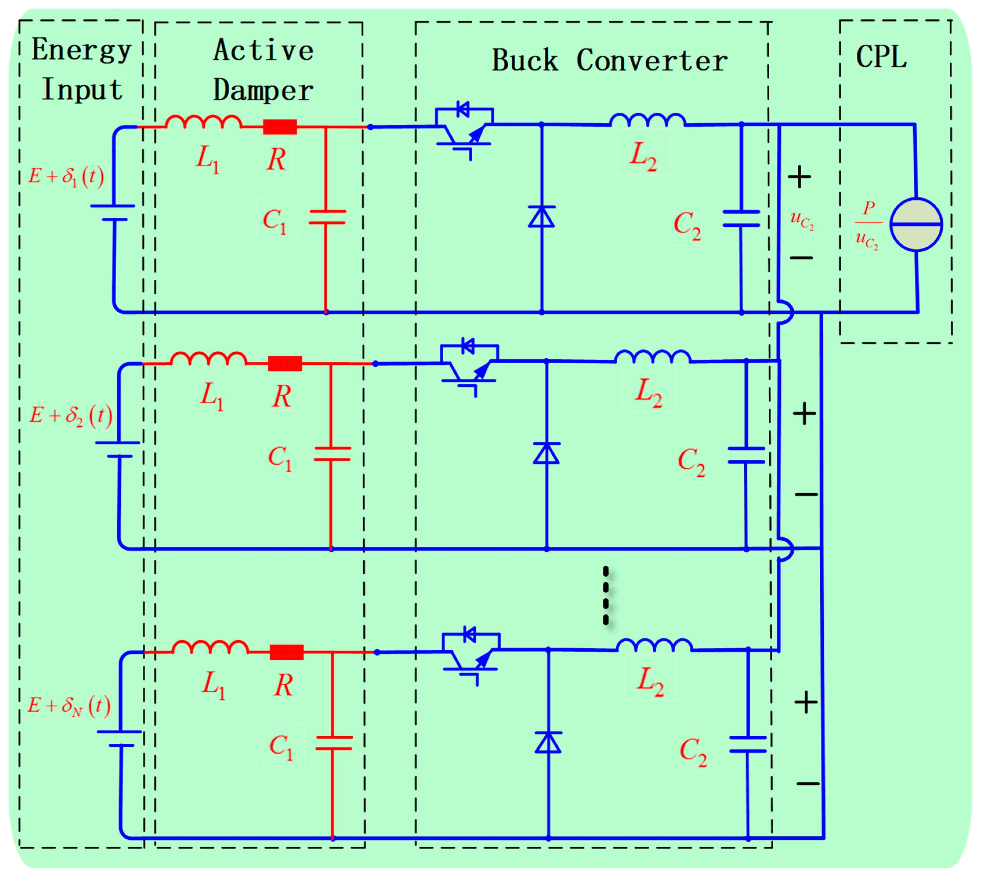
In this section, we extend the proposed stabilization method to a DC microgrid with multiple parallel-connected converters. First, the DC microgrid in Figure 6 is considered. Here, all of the converters are assumed identical.
Clearly, all of the capacitors of the Buck converter can be equivalent to a common capacitance Ceq as follows:
C e q = N C 2
Let us define x i , y i , z i as the current of inductor L1, the voltage of capacitor C1, and the current of inductor L2 for the i-th converter, respectively. We define u C as the voltage of the capacitance Ceq. According to Kirchhoff’s voltage law, the dynamics of the i-th converter can be described by the following differential equations:
{ L 1 d x i d t = E + δ i ( t ) R x i y i C 1 d y i d t = x i d z i L 2 d z i d t = d y i u C C e q d u C d t = i = 1 N z i P u C
According to (22), the following can be easily derived:
{ d d t ( i = 1 N x i ) = i = 1 N E + δ i ( t ) L 1 R L 1 ( i = 1 N x i ) 1 L 1 ( i = 1 N y i ) d d t ( i = 1 N y i ) = 1 C 1 i = 1 N x i d C 1 i = 1 N z i d d t ( i = 1 N z i ) = d L 2 i = 1 N y i N L 2 u C C e q d u C d t = i = 1 N z i P u C
We define:
x ¯ = 1 N i = 1 N x i , y ¯ = 1 N i = 1 N y i , z ¯ = 1 N i = 1 N z i
Substituting (24) into (23), the following can be obtained:
{ L 1 d d t x ¯ = E R x ¯ y ¯ + 1 N i = 1 N δ i ( t ) C 1 d d t y ¯ = x ¯ d z ¯ L 2 d d t z ¯ = d y ¯ u C C 2 d u C d t = z ¯ P N u C
Thus, a reduced-order model of the DC microgrid with multiple parallel-connected converters is obtained in (25). Obviously, the system described in (25) is equivalent to the system in (2). Hence, the small-signal stability conditions can be obtained by replacing P with P/N in (12), and the large-signal stability and DOA estimation can be assessed via the same method presented in Section 3.3.

4.2. Stability Analysis of the DC Microgrid with Multiple Non-identical Converters

In this section, we consider the DC microgrid with multiple non-identical converters. Denotes L1,i, C1,i, L2,i, and C2,i as the active damper’s inductance, capacitance, Buck converter’s inductance and capacitance of the i-th DG, respectively. Similarly, all of the capacitors of the Buck converter can be equivalent to a common capacitance Ceq as follows:
C e q = i = 1 N C 2 , i
According to Kirchhoff’s voltage law, the dynamics of the i-th converter can be described by the following differential equations:
{ L 1 , i d x i d t = E i + δ i ( t ) r i x i y i C 1 , i d y i d t = x i d i z i L 2 , i d z i d t = d i y i u C C e q d u C d t = i = 1 N z i P u C
where xi and zi are the currents through L1,i and L2,i, respectively, and z2 and uC are the voltages across C1,i and Ceq, respectively. Ei, ri, di and δ i ( t ) are the input voltage, resistance, duty cycle and uncertain disturbance of the i-th DG. Write (27) into compact form, the whole dynamics of the system can be obtained:
{ L 1 d x d t = E + δ ( t ) R x y C 1 d y d t = x D z L 2 d z d t = D y u C C e q d u C d t = i = 1 N z i P u C
where L 1 = d i a g { L 1 , i } , C 1 = d i a g { C 1 , i } , L 2 = d i a g { L 2 , i } , E = [ E 1 E 2 E N ] T , δ ( t ) = [ δ 1 δ 2 δ N ] T , x = [ x 1 x 2 x N ] T , y = [ y 1 y 2 y N ] T , u C = [ u C u C u C ] T and z = [ z 1 z 2 z N ] T . Obviously, the operation point of the system is determined by:
{ E R x y = 0 x D z = 0 D y u C = 0 i = 1 N z i P u C = 0
where 0 = [ 0 0 0 ] T . By solving (29), the load voltage of the operation point is given by:
v = i = 1 N E i d i r i + ( i = 1 N E i d i r i ) 2 4 P i = 1 N 1 d i 2 r i 2 i = 1 N 1 d i 2 r i
Linearizing (28) around the operation point, the equivalent linearized model of the system is given by:
{ L 1 d Δ x d t = δ ( t ) R Δ x Δ y C 1 d Δ y d t = Δ x D Δ z L 2 d Δ z d t = D Δ y Δ u C C e q d Δ u C d t = i = 1 N Δ z i + P v 2 Δ u C
where Δ x , Δ y , Δ z and Δ u C are the small-signal variables. According to (31), the Jacobian matrix of the system is given by:
J 1 = [ L 1 1 R L 1 1     C 1 1 O C 1 1 D     L 2 1 D O L 2 1 1 N     C e q 1 1 N T P C e q v 2 ]
where 1 N = [ 1 1 1 ] T .
Then, the system is stable if and only if J1 is Hurwitz. However, the characteristic polynomial of J1 is a high-order polynomial which analytic stability conditions are very complicated. Hence, this paper will investigate the stability in simulations. If there exist L1, C1 and R such that J1 is Hurwitz, the large-signal stability and DOA estimation can also be assessed via the same method presented in Section 3.3.

5. Simulation

To verify the effectiveness of the proposed stabilization method, simulations were carried out in MATLAB/Simulink. Let us consider the DC microgrid presented in Figure 3, where L2 = 5 mH, C2 = 5 mF, P = 500 W, d = 0.5, and E = 120 V. Term δ ( t ) is a bounded high-frequency disturbance such that | δ ( t ) | 5 , and R, L1, and C1 are the parameters that needs to be designed.

5.1. Small-Signal Stability Conditions

Let us take R = 1 Ω and C1 = 5 mF. According to (4), the operation point of the system can be obtained as (4.32, 115.68, 8.64, 57.84). According to the stability analysis, the system is stable if and only if (12) holds. Substituting the parameters into (12), the following can be obtained:
5 × 10 4 < L 1 < 7.25 × 10 3
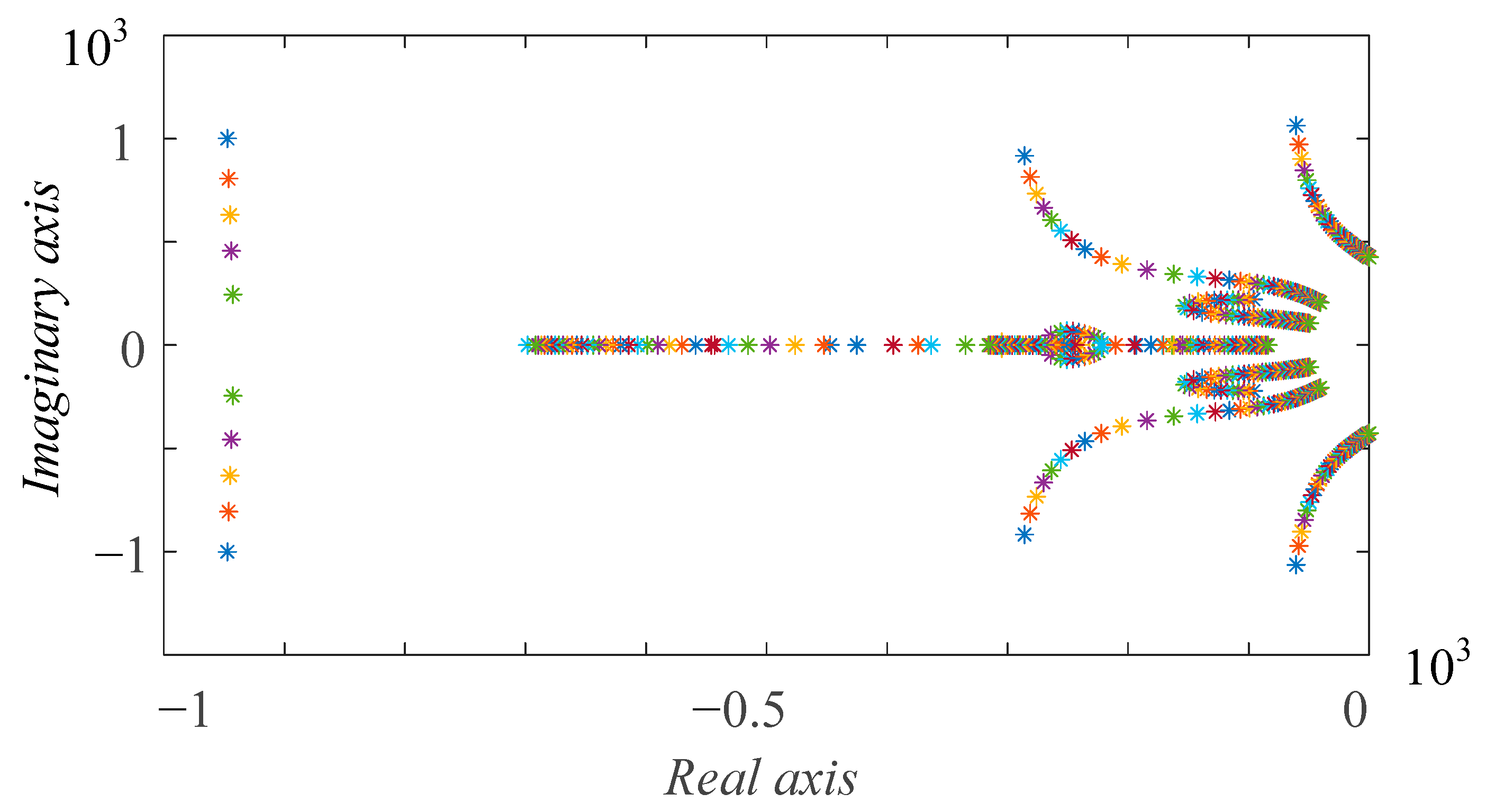
The root locus of J is presented in Figure 7 as L1 increases from 5 × 10 4 to 7.25 × 10 3 H.
The stability condition derived in [40] shows that the system is stable if (9) holds. Substituting the parameters into (12), the following can be obtained:
R > L α C α P v 2 L 1 < 33.45 × 10 3
However, the root locus presented in Figure 7 shows that the system is stable if and only if 5 × 10 4 < L 1 < 7.25 × 10 3 H. Thus, the stability criterion proposed in [40] is incorrect.

5.2. Transfer Function of the Disturbance

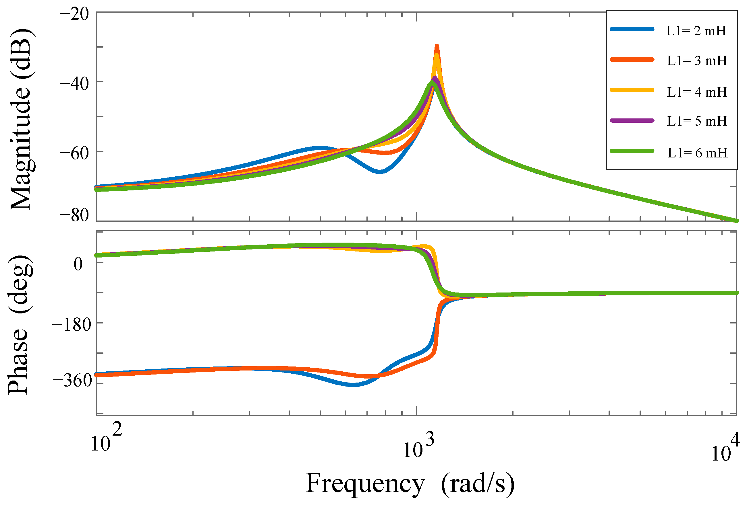
According to (20), the transfer function of the disturbance is given by G ( s ) = b T ( s I J ) 1 b . Figure 8 shows a Bode diagram of G(s) when L1 = 2, 3, 4, 5, and 6 mH. When the frequency of the disturbance is within [ 10 2 , 10 4 ] rad/s, the magnitude of the transfer function ranges from −20 dB to −80 dB. Therefore, the system has a strong ability to mitigate disturbances.

5.3. DOA of the Operation Point

Let us take L1 = 5 mH. Then, the eigenvalue of the system Jacobian matrix is given by 77.34 ± 153.68i, 7.71 ± 227.98i. According to the Lyapunov stability theorem, there is a real-symmetric positive definite matrix Q that satisfies (15). By solving (15), Q is given by:
Q = [ 0.0219 0.0194 0.0077 0.0319 0.0194 0.0452 0.0339 0.0348 0.0077 0.0339 0.0994 0.0144 0.0319 0.0348 0.0144 0.0799 ]
Then, D ( r ) = { z | z T Q z < r } is an estimation of the DOA, where r is the solution of the optimization problem described in (18). Clearly, the optimization problem in (18) can also be described as follows:
min   z T Q z s . t .   z T z + 2 f ( z ) T Q z = 0 ; z T z > 0 ; f ( z ) = [ 0 0 0 149.5 57.84 + z 4 z 4 2 ]
By using the MATLAB Optimization Toolbox, the optimal solution of (18) is obtained as r = 2.2336. Therefore, the DOA of the operation point is estimated as D = { z | z T Q z < 2.2336 } .

5.4. Compared with Virtual Resistance Method

Virtual resistance is a typical and effective stabilization method in DC microgrid [35]. A DC microgrid under virtual resistance stabilization method is presented in Figure 9b.
In Figure 9, all the parameters of the two microgrids in Figure 9 are the same except for the control strategy. i1 and i2 are the output currents of the energy supply sources. Next, we will compare the above two stabilization methods from the following three aspects: stability; the disturbance in output voltage; high-frequency harmonic components in output current of energy supply sources.

5.5. Simulation Results

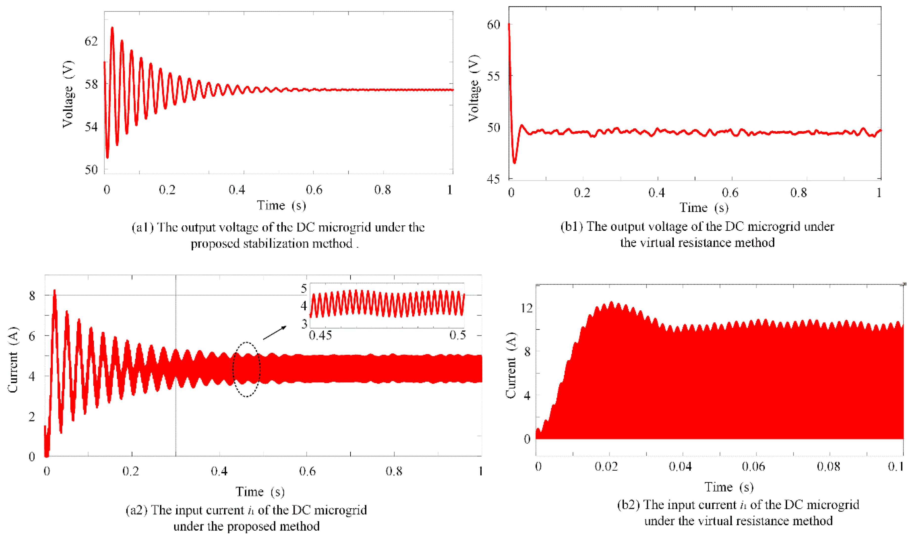
Let us take R = 1 Ω, L1 = 5 mH, and C1 = 5 mF. According to the theoretical analysis in Section 5.1 and Section 5.2, the system in Figure 9a is stable and has a strong ability to mitigate disturbances. The disturbance is assumed as δ ( t ) = 5 cos 200 π t + κ ( t ) , where κ ( t ) is a random noise that satisfies | κ ( t ) | < 5 . The frequency of the PWM signal is 10 kHz. The simulation results are presented in Figure 10.
Figure 10(a1) shows that the system is stable, verifying that the proposed stabilization method can overcome the instability of the CPL. Compared with Figure 10(b1), the disturbance of the output voltage in Figure 10(a1) is smaller, which shows that the proposed method can mitigate fluctuations from a non-ideal input and has a better performance in disturbance mitigation than the traditional virtual resistance method. Figure 10(b2) shows that output current of the energy source contains large high-frequency discontinues harmonics from switching, which will damage the energy supply source. Figure 10(b1) shows that the output current of the energy input source does not contain high-frequency harmonics from switching, demonstrating that the proposed method can mitigation the discontinuous harmonic current from the PWM.
In summary, simulation results shows that the proposed active damping method can overcome the CPL’s instability, mitigate disturbance and protect the high-frequency discontinues harmonic current from interfering with the source simultaneously.

5.6. The DC Microgrid with Multiple Identical Converters

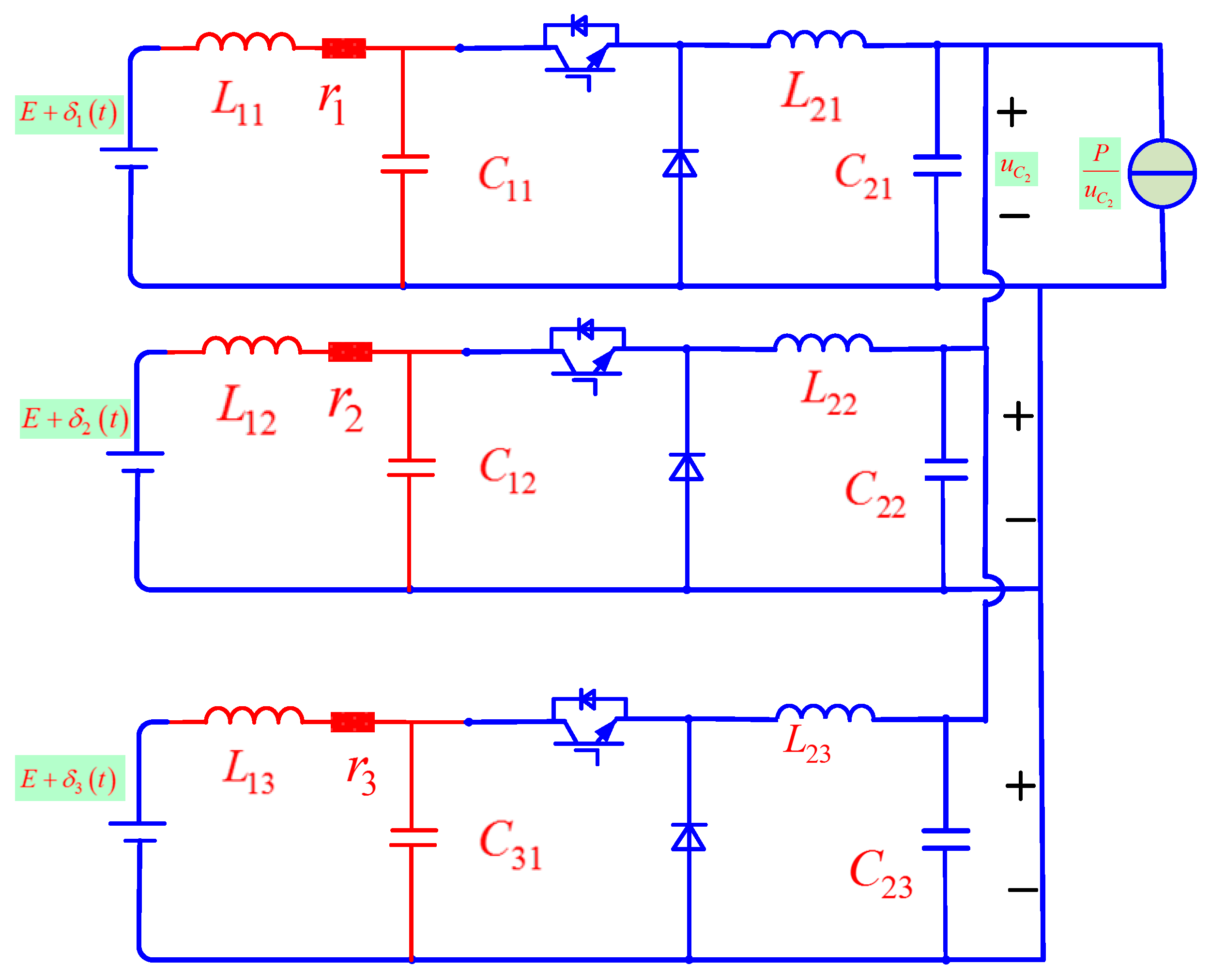
To verify the extendibility of the proposed method, we consider the DC microgrid with three converters presented in Figure 11. Take L2,1 = L2,2 = L2,3 = 5 mH, C2,1 = C2,2 = C2,3 = 5 mF, P = 1500 W, d1 = d2 = d3 = 0.5, and E1 = E2 = E3 = 120 V. δ 1 ( t ) = 5 cos 200 π t + κ ( t ) , δ 2 ( t ) = 10 cos 400 π t + κ ( t ) , and δ 3 ( t ) = 10 cos 200 π t + κ ( t ) , where κ ( t ) is a random noise that satisfies | κ ( t ) | < 5 .
Let us take r1 = r2 = r3 = 1 Ω, L1,1 = L1,2 = L1,3 = 5 mH, and C1,1 = C1,2 = C1,3 = 5 mF. Then, the converters in Figure 11 are identical. According to the theoretical analysis in Section 4, the system is stable.
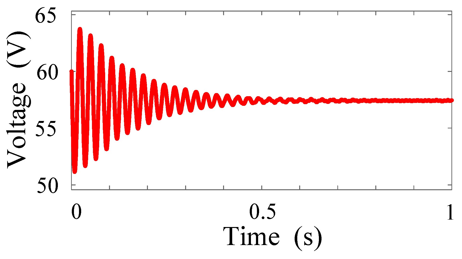
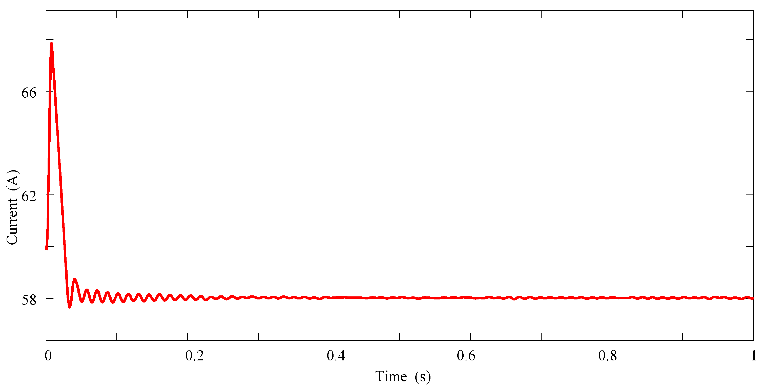
The simulation results presented in Figure 12 also show that the system is stable, and the disturbance of the output voltage is small. Therefore, the proposed method and the stability condition in (12) can be applied to a DC microgrid with multiple identical converters.

5.7. The DC Microgrid with Multiple Identical Converters

Take L2,1 = 1 mH, L2,2 = 2 mH, L2,3 = 5 mH, C2,1 = 2 mF, C2,2 = 4 mF, C2,3 = 8 mF, P = 500 W, d1 = 0.6, d2 = 0.5, d3 = 0.5, E1 = 100 V, and E2 = E3 = 120 V. δ 1 ( t ) = 5 cos 200 π t + κ ( t ) , δ 2 ( t ) = 10 cos 400 π t + κ ( t ) , and δ 3 ( t ) = 10 cos 200 π t + κ ( t ) , where κ ( t ) is a random noise that satisfies | κ ( t ) | < 10 . Then, all the converters in Figure 11 are non-identical.
Take L1,1 = 5 mH, L1,2 = 2.5 mH, L1,3 = 1 mH, r1 = r2 = r3 = 2 Ω, C1,1 = C1,2 = C1,3 = k, where k is undetermined parameter. If J1 is Hurwitz, the system will be stable. The root locus of J1 is presented in Figure 13 as k increases from 5 × 10 4 to 5.1 × 10 3 F.
Figure 13 shows that J1 is Hurwitz when 0.5 mF < k < 5.1 mF. Take C1,1 = C1,2 = C1,3 = 5 mH, then, the system is stable.
The simulation results presented in Figure 14 also show that the system is stable, and the disturbance of the output voltage is small. Therefore, the proposed method can be applicable to the DC microgrid with multiple converters.

6. Conclusions

The stability and disturbance mitigation of a DC microgrid with a CPL are investigated in this paper. Stabilization based on active damping is proposed, and the necessary and sufficient stability conditions are established. In addition, this paper demonstrates that the stability criterion derived in [40] is incorrect. Moreover, this paper develops an approach for analyzing the large-signal stability of a system based on the Lyapunov function. This paper transforms the problem of DOA estimation into an optimization problem, which can be solved by numerical techniques. This paper demonstrates that the proposed method and stability conditions can be applied to a DC microgrid with multiple converters. Finally, simulation results verify the effectiveness of the proposed method.

Author Contributions

H.L. (Haolan Liang) conceived the main idea and wrote the manuscript; Z.L. gave some useful suggestions to the manuscript; H.L. (Hua Liu) performed some of the theoretical analysis and provided mathematical guidance.

Funding

This research received no external funding.

Conflicts of Interest

The authors declare no conflict of interest.

References

  1. Cagnano, A.; de Tuglie, E.; Cicognani, L. Prince—Electrical Energy Systems Lab: A pilot project for smart microgrids. Electr. Power Syst. Res. 2017, 148, 117–148. [Google Scholar] [CrossRef]
  2. Song, D.; Li, Q.; Cai, Z.; Li, L.; Yang, J.; Su, M.; Joo, Y.H. Model predictive control using multi-step prediction model for electrical yaw system of horizontal-axis wind turbines. IEEE Trans. Sustain. Energy 2018. [Google Scholar] [CrossRef]
  3. Song, D.; Fan, X.; Yang, J.; Liu, A.; Chen, S.; Joo, Y.H. Power extraction efficiency optimization of horizontal-axis wind turbines through optimizing control parameters of yaw control systems using an intelligent method. Appl. Energy 2018, 224, 224–279. [Google Scholar] [CrossRef]
  4. Rodríguez-Licea, M.A.; Pérez-Pinal, F.J.; Nuñez-Perez, J.C.; Herrera-Ramirez, C.A. Nonlinear Robust Control for Low Voltage Direct-Current Residential Microgrids with Constant Power Loads. Energies 2018, 11, 1130. [Google Scholar] [CrossRef]
  5. Hossain, E.; Perez, R.; Padmanaban, S.; Siano, P. Investigation on the Development of a Sliding Mode Controller for Constant Power Loads in Microgrids. Energies 2017, 10, 1086. [Google Scholar] [CrossRef]
  6. Shuai, Z.; Peng, Y.; Liu, X.; Li, Z.; Guerrero, J.M.; Shen, Z.J. Dynamic Equivalent Modeling for Multi-Microgrid Based on Structure Preservation Method. IEEE Trans. Smart Grid 2018. [Google Scholar] [CrossRef]
  7. Wang, Y.; Wang, X.; Chen, Z.; Blaabjerg, F. Small-signal stability analysis of inverter-fed power systems using component connection method. IEEE Trans. Smart Grid 2018, 9, 5310–5390. [Google Scholar] [CrossRef]
  8. Shuai, Z.; Peng, Y.; Guerrero, J.M.; Li, Y.; Shen, Z.J. Transient Response Analysis of Inverter-Based Microgrids Under Unbalanced Conditions Using a Dynamic Phasor Model. IEEE Trans. Ind. Electron. 2019, 66, 2866–2879. [Google Scholar] [CrossRef]
  9. Sun, Y.; Hou, X.; Yang, J.; Han, H.; Su, M.; Guerrero, J.M. New perspectives on droop control in AC microgrid. IEEE Trans. Ind. Electron. 2017, 64, 5741–5745. [Google Scholar] [CrossRef]
  10. Han, H.; Li, L.; Wang, L.; Su, M.; Zhao, Y.; Guerrero, J.M. A Novel Decentralized Economic Operation in Islanded AC Microgrids. Energies 2017, 10, 804. [Google Scholar] [CrossRef]
  11. Rana, M.M.; Li, L.; Su, S.W. Controlling the renewable microgrid using semidefinite programming technique. Int. J. Electr. Power Energy Syst. 2017, 84, 231–284. [Google Scholar] [CrossRef]
  12. Liu, Z.; Su, M.; Sun, Y.; Li, L.; Han, H.; Zhang, X.; Zheng, M. Optimal criterion and global/sub-optimal control schemes of decentralized economical dispatch for AC microgrid. Int. J. Electr. Power Energy Syst. 2019, 104, 104–142. [Google Scholar] [CrossRef]
  13. Han, H.; Hou, X.; Yang, J.; Wu, J.; Su, M.; Guerrero, J.M. Review of power sharing control strategies for islanding operation of AC microgrids. IEEE Trans. Smart Grid 2016, 7, 215–217. [Google Scholar] [CrossRef]
  14. Li, L.; Sun, Y.; Liu, Z.; Hou, X.; Shi, G.; Su, M. A Decentralized Control with Unique Equilibrium Point for Cascaded-type Microgrid. IEEE Trans. Sustain. Energy 2019, 10, 310–326. [Google Scholar] [CrossRef]
  15. Hou, X.; Sun, Y.; Han, H.; Liu, Z.; Yuan, W.; Su, M. A fully decentralized control of grid-connected cascaded inverters. IEEE Trans. Sustain. Energy 2019, 10, 310–317. [Google Scholar] [CrossRef]
  16. Hou, X.; Sun, Y.; Zhang, X.; Zhang, G.; Lu, J.; Blaabjerg, F. A Self-Synchronized Decentralized Control for Series-Connected H-bridge Rectifiers. IEEE Trans. Power Electron. 2019. [Google Scholar] [CrossRef]
  17. Sun, Y.; Shi, G.; Li, X.; Yuan, W.; Su, M.; Han, H.; Hou, X. An f-P/Q droop control in cascaded-type microgrid. IEEE Trans. Power Electron. 2018, 33, 1133–1138. [Google Scholar]
  18. Masud, R.; Li, L.; Steven, S. Design of Distributed Controllers for Microgrids. Int. J. Innov. Comput. Inf. Control 2017, 13, 1–12. [Google Scholar]
  19. Masud, R.; Li, L. An overview of distributed microgrid state estimation and control for smart grids. Sensors 2015, 15, 4315–4325. [Google Scholar]
  20. Cagnano, A.; Bugliari, A.C.; de Tuglie, E. A cooperative control for the reserve management of isolated microgrids. Appl. Energy 2018, 218, 218–265. [Google Scholar] [CrossRef]
  21. Guo, F.; Wen, C.; Song, Y.-D. Distributed Control and Optimization Technologies in Smart Grid Systems; CRC Press: Boca Raton, FL, USA, 2017. [Google Scholar]
  22. Wang, Y.; Wang, X.; Chen, Z.; Blaabjerg, F. Distributed optimal control of reactive power and voltage in islanded microgrids. IEEE Trans. Ind. Appl. 2017, 53, 349–353. [Google Scholar] [CrossRef]
  23. Hou, X.; Sun, Y.; Lu, J.; Zhang, X.; Hai, K.L.; Su, M.; Guerrero, J.M. Distributed Hierarchical Control of AC Microgrid Operating in Grid-Connected, Islanded and Their Transition Modes. IEEE Access 2018. [Google Scholar] [CrossRef]
  24. Guo, F.; Xu, Q.; Wen, C.; Wang, L.; Wang, P. Distributed Secondary Control for Power Allocation and Voltage Restoration in Islanded DC Microgrids. IEEE Trans. Sustain. Energy 2018, 9, 1869–1900. [Google Scholar] [CrossRef]
  25. Wang, Y.; Chen, Z.; Wang, X.; Tian, Y.; Tan, Y.; Yang, C. An estimator-based distributed voltage predictive control strategy for AC islanded microgrids. IEEE Trans. Power Electron. 2015, 30, 2930–3951. [Google Scholar] [CrossRef]
  26. Guo, F.; Wen, C.; Mao, J.; Song, Y. Distributed economic dispatch for smart grids with random wind power. IEEE Trans. Smart Grid 2016, 7, 1583–1587. [Google Scholar] [CrossRef]
  27. Yang, J.; Yuan, W.; Sun, Y.; Han, H.; Hou, X.; Guerrero, J.M. A novel quasi-master-slave control frame for PV-storage independent microgrid. Int. J. Electr. Power Energy Syst. 2017, 97, 274–297. [Google Scholar] [CrossRef]
  28. Kwasinski, A.; Onwuchekwa, C.N. Dynamic Behavior and Stabilization of DC Microgrids with Instantaneous Constant-Power Loads. IEEE Trans. Power Electron. 2011, 26, 822–834. [Google Scholar] [CrossRef]
  29. Gu, Y.; Li, W.; He, X. Passivity-Based Control of DC Microgrid for Self-Disciplined Stabilization. IEEE Trans. Power Electron. 2015, 30, 2630–2632. [Google Scholar]
  30. Kwasinski, A.; Krein, P.T. Stabilization of constant power loads in dc-dc converters using passivity based control. In Proceedings of the 29th International Telecommunications Energy Conference, Rome, Italy, 30 September–4 October 2007; pp. 867–874. [Google Scholar]
  31. Magne, P.; Mobarakeh, B.N.; Pierfederici, S. Dynamic Consideration of DC Microgrids With Constant Power Loads and Active Damping System—A Design Method for Fault-Tolerant Stabilizing System. IEEE J. Emerg. Sel. Top. Power Electron. 2014, 2, 570–572. [Google Scholar] [CrossRef]
  32. Chang, X.; Li, Y.; Li, X.; Chen, X. An Active Damping Method Based on a Supercapacitor Energy Storage System to Overcome the Destabilizing Effect of Instantaneous Constant Power Loads in DC Microgrids. IEEE Trans. Energy Convers. 2017, 32, 32–47. [Google Scholar] [CrossRef]
  33. Wu, M.; Lu, D.D. An active damping method for stabilization of cascaded connected two stage converter systems with constant power loads in DC microgrids. In Proceedings of the 2014 IEEE International Symposium on Circuits and Systems, Melbourne, VIC, Australia, 1–5 June 2014; pp. 2664–2667. [Google Scholar]
  34. Zhang, X.; Zhong, Q.; Ming, W. Stabilization of Cascaded DC/DC Converters via Adaptive Series-Virtual-Impedance Control of the Load Converter. IEEE Trans. Power Electron. 2016, 31, 6031–6063. [Google Scholar] [CrossRef]
  35. Lu, X.; Sun, K.; Guerrero, J.M.; Vasquez, J.C.; Huang, L.; Wang, J. Stability Enhancement Based on Virtual Impedance for DC Microgrids with Constant Power Loads. IEEE Trans. Smart Grid 2015, 6, 2783–2786. [Google Scholar] [CrossRef]
  36. Zhang, X.; Zhong, Q.; Ming, W. Stabilization of a Cascaded DC Converter System via Adding a Virtual Adaptive Parallel Impedance to the Input of the Load Converter. IEEE Trans. Power Electron. 2016, 31, 1831–1832. [Google Scholar] [CrossRef]
  37. Herrera, L.; Zhang, W.; Wang, J. Stability Analysis and Controller Design of DC Microgrids with Constant Power Loads. IEEE Trans. Smart Grid 2017, 8, 800–888. [Google Scholar]
  38. Marx, D.; Magne, P.; Nahid-Mobarakeh, B.; Pierfederici, S.; Davat, B. Large signal stability analysis tools in DC power systems with constant power loads and variable power loads—A review. IEEE Trans. Power Electron. 2012, 27, 1727–1787. [Google Scholar] [CrossRef]
  39. Brayton, R.K.; Moser, J.K. A theory of nonlinear Networks I. Q. Appl. Math. 1964, 22, 22–33. [Google Scholar]
  40. Liu, X.; Zhou, Y.; Zhang, W.; Ma, S. Stability Criteria for Constant Power Loads With Multistage LC Filters. IEEE Trans. Veh. Technol. 2011, 60, 2049–2060. [Google Scholar] [CrossRef]
  41. Karimipour, D.; Salmasi, F.R. Stability Analysis of AC Microgrids With Constant Power Loads Based on Popov’s Absolute Stability Criterion. IEEE Trans. Circuits Syst. II 2015, 62, 700–760. [Google Scholar] [CrossRef]
  42. Rahimi, A.M.; Williamson, G.A.; Emadi, A. Loop-Cancellation Technique: A Novel Nonlinear Feedback to Overcome the Destabilizing Effect of Constant-Power Loads. IEEE Trans. Veh. Technol. 2010, 59, 659–661. [Google Scholar] [CrossRef]
  43. Sulligoi, G.; Bosich, D.; Giadrossi, G.; Zhu, L.; Cupelli, M.; Monti, A. Multiconverter Medium Voltage DC Power Systems on Ships: Constant-Power Loads Instability Solution Using Linearization via State Feedback Control. IEEE Trans. Smart Grid 2014, 5, 2552–2555. [Google Scholar] [CrossRef]
  44. Zhao, Y.; Qiao, W.; Ha, D. A Sliding-Mode Duty-Ratio Controller for DC/DC Buck Converters With Constant Power Loads. IEEE Trans. Ind. Appl. 2014, 50, 1448–1458. [Google Scholar] [CrossRef] [Green Version]
  45. Su, M.; Liu, Z.; Sun, Y.; Han, H.; Hou, X. Stability Analysis and Stabilization methods of DC Microgrid with Multiple Parallel-Connected DC-DC Converters loaded by CPLs. IEEE Trans. Smart Grid 2018, 9, 142–149. [Google Scholar] [CrossRef]
  46. Anand, S.; Fernandes, B.G. Reduced-Order Model and Stability Analysis of Low-Voltage DC Microgrid. IEEE Trans. Ind. Electron. 2013, 60, 5040–5049. [Google Scholar] [CrossRef]
  47. Tahim, A.P.N.; Pagano, D.J.; Lenz, E.; Stramosk, V. Modeling and Stability Analysis of Islanded DC Microgrids Under Droop Control. IEEE Trans. Power Electron. 2015, 30, 4607–4630. [Google Scholar] [CrossRef]
  48. Liu, Z.; Su, M.; Sun, Y.; Han, H.; Hou, X.; Guerrero, J.M. Stability analysis of DC microgrids with constant power load under distributed control methods. Automatica 2018, 90, 72–90. [Google Scholar] [CrossRef]
  49. Liu, Z.; Su, M.; Sun, Y.; Yuan, W.; Han, H. Existence and Stability of Equilibrium of DC Microgrid with Constant Power Loads. IEEE Trans. Power Syst. 2018, 33, 7011–7033. [Google Scholar] [CrossRef]
Figure 1. A simplified model of a DC microgrid.
Energies 12 00873 g001
Figure 2. An equivalent average model of the DC microgrid.
Energies 12 00873 g002
Figure 3. The proposed active damping circuit of the DC microgrid.
Energies 12 00873 g003
Figure 4. An equivalent average model of the DC microgrid with the proposed active damper.
Energies 12 00873 g004
Figure 5. Topology structure of a DC microgrid with N-stage LC filters.
Energies 12 00873 g005
Figure 6. A DC microgrid with N parallel-connected converters.
Energies 12 00873 g006
Figure 7. The root locus of the system Jacobian matrix.
Energies 12 00873 g007
Figure 8. Bode diagram of the transfer function of the disturbance.
Energies 12 00873 g008
Figure 9. The topologies of the DC microgrid under two different stabilization methods.
Energies 12 00873 g009
Figure 10. Simulation results.
Energies 12 00873 g010
Figure 11. DC microgrid with three converters.
Energies 12 00873 g011
Figure 12. Output voltage of a DC microgrid with three identical converters.
Energies 12 00873 g012
Figure 13. The root locus of the Jacobian matrix J1.
Energies 12 00873 g013
Figure 14. Output voltage of a DC microgrid with three non-identical converters.
Energies 12 00873 g014