Abstract
In this study, a method to determine the optimal generator operating point is proposed to enhance the utilization of power resources in a range-extended electric vehicle (Re-EV). Currently, the Re-EV is being developed as one of the solutions to the short driving range and charge problem of electric vehicles (EVs). In particular, we present a method for flexibly determining the operating point of the generators mounted on Re-EVs based on the power consumption trends of the users. Our proposed method can address the problem in existing algorithms wherein all the available resources are not utilized, even though there is fuel remaining in the EV because the battery is not completely discharged. The proposed algorithm was developed based on data acquired through actual driving tests using an agricultural utility vehicle; these data can be applied to various power consumption patterns, including nonlinear consumption patterns. In addition, this algorithm can be applied to other types of Re-EV with different battery and generator specifications. We perform simulations and experiments to verify the proposed algorithm and the results demonstrate the effectiveness of the proposed approach compared with other existing methods.
1. Introduction
The increasing air pollution around the world has prompted the development of methods to reduce it owing to its harmful environmental effects; in addition, related environmental regulations are being reinforced towards achieving this goal. Furthermore, governments in various countries are promoting the distribution of eco-friendly vehicles through support and various taxation policies. Considering this, the automotive industry is developing eco-friendly, high-efficiency vehicles to reduce polluting exhaust gas emissions; among these eco-friendly vehicles, electric vehicles (EVs) are slowly gaining prevalence and becoming increasingly efficient.
EVs have a short driving range; in addition, the charging infrastructure for EVs is currently insufficient. These two reasons limit the usability of EVs by drivers. Considering this, the problems of limited driving range, long charging time, limited lifetime, and high upfront costs associated with EVs need to be addressed. In general, EVs store energy using batteries, which are bulky, heavy, and expensive; therefore, it is considerably difficult to design practical EVs [1,2,3].
It is evident that increasing the battery capacity of EVs can increase their driving range; however, owing to issues related to battery weight and costs, it is not possible to indefinitely increase battery capacity in EVs [4,5,6,7,8]. Furthermore, in other efforts to extend the driving range of EVs, methods of maximizing their power conversion efficiency by reducing air and ground resistance as well as decreasing their weight have already been developed; it is noteworthy that these methods are not significantly different from those used in conventional vehicles using internal combustion engines. Thus, to effectively address the problem of short driving ranges of EVs, range-extended EV (Re-EV) technology, which involves the installation of small range extenders in EVs, is being developed [9,10,11,12,13,14,15,16,17]. In particular, Re-EV technology can overcome the driving range limitations of EVs and can be useful while the EV charge infrastructure is not sufficiently developed.
As shown in Table 1, though the Re-EV is a type of plug-in hybrid EV, it emphasizes the advantages of EVs by minimizing the engine size compared with typical hybrid vehicles and increasing the battery capacity by utilizing internal combustion engines not for driving, but for charging the battery [11,12,13,14,15,18,19,20,21,22,23,24].

Table 1.
Comparison by type of electric vehicles.
In the case of series hybrid vehicles [8,10,25], such as Re-EVs, the generator is operated at a fixed point based on the state of charge (SOC) of the battery, because the internal combustion engines in serial hybrid vehicles are not used for driving. In particular, Re-EVs consist of an engine and generator, i.e., a genset, which could provide extra electric power for charging the on-board battery, thus extending the traveling distance of the Re-EVs. [1,4,5,6,7,12,13,14,15,16]. This increase of available energy can make Re-EVs suitable for use as various purpose-built vehicles, such as agricultural and industrial vehicles. Vehicles serving multiple functions, such as agricultural and industrial vehicles, often use battery power in addition to combustion engines, so it is not appropriate to control only the power, used for driving.
In the literature, various energy management methods for Re-EVs have been proposed, which primarily focus on optimizing fuel economy and fuel energy. These energy management methods can be classified into two categories, namely rule-based and optimization-based methods [16]. In rule-based energy management approaches, conventionally, the Re-EV is initially operated in a purely electric mode; however, when the SOC of the battery is below a certain threshold level, it is operated in the sustain mode. In contrast, some studies use optimization-based approaches to EV design, such as those involving equivalent consumption minimization strategy (ECMS), equivalent fuel consumption optimal control strategy (EFCOCS) [4,5,6], and dynamic programming (DP) methods [10,26].
In a rule-based energy management strategy, if the set threshold level is too high, the advantages of EVs cannot be fully exploited. In contrast, a considerably low threshold level will lead to complete discharge of the EV battery with fuel remaining in the EV. Though optimization-based strategies provide optimal solutions, these techniques require relatively long computation times and prior knowledge of an unknown driving cycle. Furthermore, many studies on hybrid EVs aim to minimize the use of fuel-based internal combustion engines; however, this paper aims to determine the operating point by turning on the generator in a flexible manner such that all the remaining fuel energy can be utilized.
We propose an advanced rule-based energy management method for Re-EVs; if the user consumes a significant amount of power in a short time, it is possible that the EV battery gets discharged without any fuel remaining to run the generator. The energy management method currently considered for the proposed Re-EV system is the charging-deplete and charging-sustain (CD-CS) method, which is similar to the rule-based method [27,28,29]. In addition, when the user consumes low power, it can delay the start-up of the generator and make full use of the merits of an EV. In particular, the proposed method aims at determining the operating point of electric generators based on the power consumption trend of the users, and exploiting the Re-EV energy sources at an appropriate time, using data acquired through actual driving tests.
The remainder of this paper is organized as follows: Section 2 describes the configuration of the Re-EV system. The energy management problem and proposed operating point determination method are presented in Section 3. Then, Section 4 discusses the process of identifying the influence of unit time length on the proposed algorithm through simulation of various scenarios. Section 5 presents the analysis of the power consumption data from a vehicle obtained via an actual driving test, while Section 6 includes information on the application of this data to the proposed algorithm. The discussion about results of algorithm applied to actual driving data, are given in Section 7. Finally, our conclusions are presented in Section 8.
2. Configuration of the Agricultural Re-EV System
The most prominent difference between Re-EVs and EVs is that the battery capacity is smaller in the case of the former; in addition, Re-EVs include an engine for power generation, as well as a generator and fuel tank. Depending on the purpose of the vehicle, batteries of different capacities and generators of different outputs can be installed. Figure 1 shows the system configuration of an agricultural Re-EV, which includes various other power consumption patterns aside from driving.
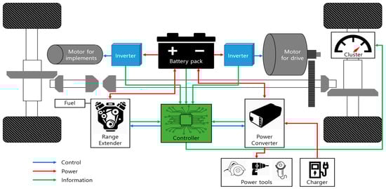
Figure 1.
Agricultural Re-EV system configuration.
In this study, we devised an Re-EV system using a 10-kWh battery, 3-kW generator, and a fuel tank sufficiently large to allow generator operation for up to 90 min; these and other component parameters are listed in Table 2. Here, driving is a major power-consumption pattern; however, the use of implements, such as crop duster or sprayer, and the use of power tools are additional patterns of consumption. Therefore, the proposed algorithm involves analyzing actual driving data and operates on the basis of battery condition to include additional power consumption. It should be noted that though this system configuration is used to analyze the proposed algorithm, the algorithm can also be applied to systems with different battery capacities, generator outputs, and fuel tank capacities. The proposed algorithm is designed based on agricultural electric vehicles, but it can also be applied to general Re-EVs.
Table 2.
Main component parameters of the Re-EV.
3. Flexible Generator Operating Point Determination Method for Re-EVs
Figure 2 shows the variations in generator operating point based on power consumption by the user. In particular, the proposed algorithm was compared to a conventional algorithm as well as a pure electric vehicle under different power consumption conditions; for this purpose, it was assumed that the conventional algorithm operated the generator at a constant SOC of 20%. Using the proposed algorithm, the generator is operated late in the case the user’s power consumption is low, thus extending the operating time of the EV system; in contrast, when the user’s power consumption is high, the generator is operated sooner so that all the remaining fuel could be utilized.
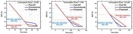
Figure 2.
Varying generator operating point based on user power consumption.
The primary objective of the proposed algorithm is the complete utilization of available fuel; in this study, the operating time, which is determined by the amount of fuel, can be a maximum of 90 min, as stated earlier. In this system, the output power of the generator is constant, and the generator does not stop during operation until the user turns it off or the Re-EV runs out of fuel. Therefore, fuel energy can be obtained as a product of the generator output and generator operating time as follows:
Further, the energy available to the user is the sum of the battery energy and fuel energy:
Substituting Equation (1) in Equation (2), Equation (3) is obtained:
If the energy consumption is greater than the available energy, the battery would completely discharge with fuel remaining. Considering this, the generator should be operated when the available energy is more than energy to be consumed, Thus, Equation (4) holds.
The amount of energy consumed by the vehicle during the generator’s operating time can be obtained by multiplying the consumption power and operating time as follows:
Substituting Equations (3) and (5) in Equation (4), Equation (6) is obtained:
To maximize the operating time of the EV by utilizing all remaining fuel, the point of complete battery discharge and point of complete fuel depletion were matched. Here, complete battery discharge refers to discharge up to the cut-off voltage within the operating range of the battery, i.e., the allowable discharge range. Thus, the following equation is obtained:
Rearranging Equation (7), corresponding to the generator operating point can be obtained as follows:
Because the output power and operating time of the generator are fixed values, the operating point of the generator is determined by comparing the remaining battery energy with the energy to be consumed.
In real-world environments, wherein an actual vehicle is used, the battery usage graph is nonlinear. To obtain the appropriate generator operating point, it is necessary to determine the power consumption based on the user’s power consumption trend, i.e., based on the slope of the graph, as shown in Figure 3. In particular, the slope of the graph is the change in SOC per unit time; this is represented by Equation (8):
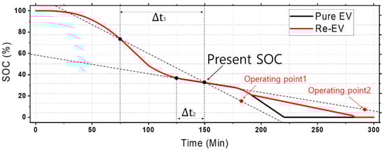
Figure 3.
Operating point determination in the case of non-linear power consumption.
Substituting Equation (8) in Equation (7), Equation (9) is obtained:
Considering the present SOC indicated in Figure 3, the graph has different slopes at unit times and ; consequently, there are different operating points, i.e., Operating Points 1 and 2. If these operating points attain the value of the present SOC, then the generator is operated. Unit time is the value set in the algorithm as the observation period of the moving average method, and according to its length, the variation of SOC is observed. Because energy to be consumed is regarded based on the degree of change in SOC, it is important to set the unit time appropriately.
4. Simulation Results
4.1. Proposed Energy Resource Management Algorithm for the Re-EVs
The key of the energy resource management algorithm is to appropriately determine current consumption power values. To identify the characteristics of the proposed algorithm and set the appropriate unit time for consumption power, a simulator capable of comparing the generator operating points and SOC change graphs based on unit time change was constructed, as shown in Figure 4. In addition, the results for the existing algorithm operating at a fixed point as well as the SOC change graph of an EV without a generator were also compared.
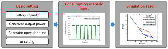
Figure 4.
Simulation configuration.
4.2. Simulation Scenarios for Consumption Power in Re-EV Systems
Simulations were performed for 10 power consumption scenarios (Cases 1–10) reflecting various power consumption patterns (constant, increasing, decreasing, irregular) as shown in Figure 5.
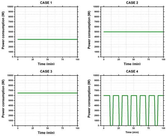
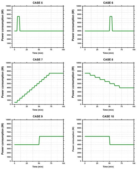
Figure 5.
Power consumption scenarios.
Cases 1–3 involve different, yet constant power consumption values (3.5, 5 and 6.5 kW). In Case 4, the vehicle is operated at 6 kW for 10 min and stopped for 5 min between the operation cycles. Cases 5 and 6 involve constant high power consumption (7.5 kW) for 5 min. Cases 7 and 8 involve gradual increase and decrease of consumption power, respectively. Lastly, Cases 9 and 10 involve a sudden increase and decrease of consumption power after a certain period of time, respectively.
4.3. Simulation Results for Re-EV Power Consumption
For simulations, the power consumption unit time was set to 1, 10, 30, and 60 min; then, the obtained results were compared.
Figure 6 shows the simulation results for power consumption scenarios. In Cases 1–3, the slope of the SOC change graph is constant when constant power is utilized. Therefore, the generator operating point did not change based on unit time, instead it changed based on the difference in power consumption.
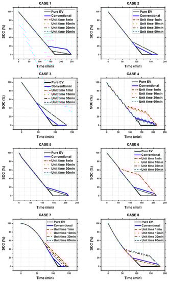
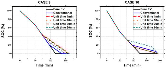
Figure 6.
Simulation results for power consumption scenarios.
In contrast, for the cases involving constant high power consumption for a short period of time, the generator was not operated when the SOC was sufficient; however, when it was operated, it was done so earlier than necessary when the battery had been consumed to some extent. In particular, when the unit time is relatively long, it is important to not operate the generator in the case of high power consumption for short periods of time.
In the graphs wherein the power consumption slowly increased or decreased, when the unit time of power consumption was short, appropriate generator operating points were obtained. However, when the unit time increased, the generator was operated earlier or later than it was necessary because the algorithm became insensitive to the change in power consumption trends. Thus, to find an appropriate generator operating point, it is necessary to ensure that the unit time of power consumption is as short as possible.
In summary, when the SOC change graph is closer to a linear form, the change in the slope is not significant; therefore, changes caused by the unit time difference are not significant. In contrast, in nonlinear consumption patterns, the algorithm becomes insensitive or hypersensitive depending on the unit time setting.
In particular, because the algorithm becomes more sensitive as the unit time decreases, it operates the generator earlier than necessary when the power consumption increases suddenly for a short period of time. On the contrary, because the algorithm becomes more insensitive to the power consumption trend change as the unit time increases, it is not able to find an appropriate generator operating point. Therefore, it is necessary to set the shortest unit time and find a method for filtering scenarios when high power consumption occurs within a short period of time to ensure that an appropriate generate operating point is found.
5. Actual Driving Experiments
As specified in Section 4, the unit time for the energy management algorithm should be set as short as possible; in addition, the algorithm should filter out short-term high power consumption data. In particular, long-term increases in power consumption should be included and short-term increases in power consumption should be filtered. To classify these trends of power consumption, an actual EV was driven, and data were collected and analyzed to identify the power consumption increase patterns depending on acceleration, loading, uphill driving, and rough road driving.
5.1. Specifications of the Agricultural Utility Vehicle Used for the Experiment
As shown in Figure 7 and Table 3, the driving test was conducted using an agricultural utility vehicle with a 10-kWh battery capacity using a motor with a 7-kW rated power capability, which is quite similar to the configuration of the Re-EV considered in this study. Data on the SOC and power consumption were acquired using the battery management system (BMS) mounted on the vehicle.

Figure 7.
Agricultural utility vehicle used for actual driving experiment.
Table 3.
Specifications of the agricultural utility vehicle.
5.2. Analysis of the Power Consumption Pattern in the Experiment
To observe the increase in power consumption based on acceleration, the vehicle was tested while it was repeatedly driven and stopped. In the beginning of experiment, high power consumption was observed for approximately 5–15 min, as shown in Figure 8. In addition, when it was driven after stopping, high power consumption was observed for a considerably short period of time.
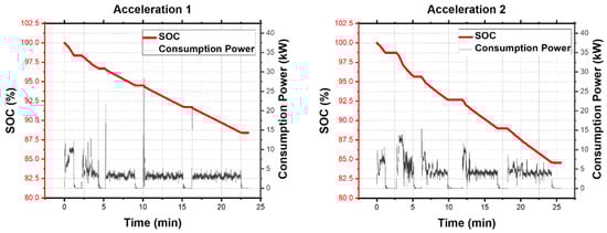
Figure 8.
Power consumption trend based on acceleration.
To observe the increase in power consumption based on loading, the vehicle was loaded with 100 kg and 200 kg and it was repeatedly driven and stopped in the same manner as in the abovementioned test for acceleration. The high-power consumption pattern for a short period of time was the fixed to be the same as the test for acceleration. The overall average power consumption was slightly higher compared with an unloaded vehicle, as shown in Figure 9.
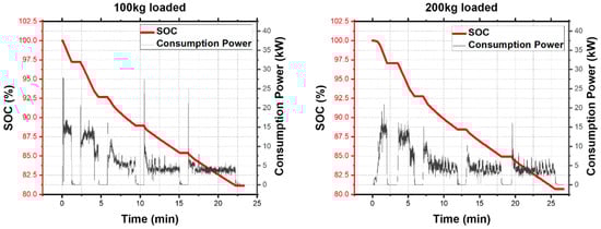
Figure 9.
Power consumption trend based on loading.
To observe the increase in power consumption in the case of uphill driving, the power consumption was observed while the vehicle repeatedly climbed ramps at 6°, 10°, 12°, and 18°. Higher power consumption was observed momentarily in these cases compared with flat road driving; however, this power consumption increase was for a short time, as shown in Figure 10. The average power consumption, including for flat road and downhill driving after uphill driving, was not significantly different from that observed during normal driving. Climb circumstances while driving that last for more than 15 min are rare in the real world, especially in the case of agricultural vehicles. Thus, power consumption due to uphill driving involves instantaneous increases that are not sustained for a long time.
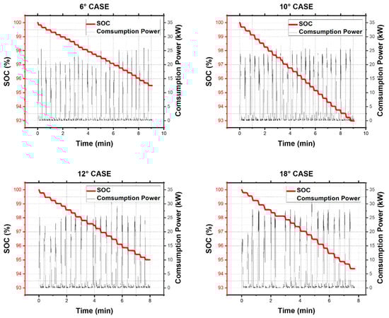
Figure 10.
Power consumption trend based on uphill driving angle.
To observe the increase in power consumption owing to rough road driving, the vehicle was driven at its maximum speed (30 km/h) on an unpaved road. The power consumption at the maximum speed was slightly higher than when the vehicle was driven on a normal road, as shown in Figure 11, but the power consumption was predicted to be lower because it is difficult to drive at a high speed in actual driving situations, such as on severe unpaved roads and roads with bumps on them.
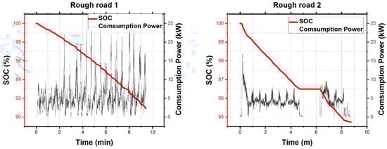
Figure 11.
Power consumption trend during rough road driving.
In summary, through our experimental tests, the cases for significant power consumption for short periods of time were confirmed, aside from the consistent power consumption increase by loading, corresponding to the 5–15 min interval in the beginning of driving and considerably short time periods during uphill climbing and acceleration.
6. Design of Algorithm based on Actual Driving Test Data
6.1. Filtering Method of Short-term High Power Consumption
The most important part of the proposed algorithm is filtering the high power consumption intervals of 5–15 min in the beginning of the drives. By filtering the data simply by changing the unit time, the required unit time becomes considerably long, owing to which the insensitivity problem is encountered. Therefore, the unit time was set to not exceed 15 min based on the driving data.
Thus, the algorithm involved comparing 1-min unit times and 15-min unit times to filter rapid increases in power consumption. Thus, the algorithm filters increase in power consumption based on a 15-min unit time, reflecting current underuse and responding sensitively to reduction in power consumption.
As stated in Equation (2), the generator is operated at a time when and is identical. It means that consumption power threshold at which the generator is operated, is set at , depending on the current energy resources. Comparing each average unit time consumption power with , eight classification trends can be obtained, as listed in Table 4, where Consumption 1 is the 1-min average consumption power from 15-min ago, Consumption 2 is the recent 15-min average consumption power, and Consumption 3 is the recent 1-min average consumption power, as shown in Figure 12. Since consumption power cannot exactly match the threshold value, it is described as High or Low compared to the threshold value.
Table 4.
Power consumption trend classification.
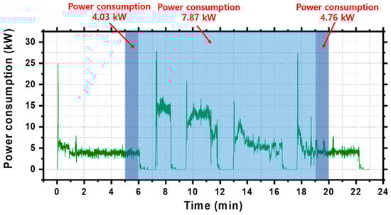
Figure 12.
Comparison-based filtering method.
In Situations 1–4, recent 1-min average power consumption is lower than , which indicates that the current power consumption is low. Situations 5 and 6 involve instantaneous, but not sustained increases in power consumption. In Situation 7, short-term, but sustained increase of power consumption is observed. Lastly, Situation 8 involves an increase in power consumption that lasts for more than 15-min, and thus, the generator is operated.
6.2. Algorithm Flowchart
Figure 13 shows the flowchart of the proposed algorithm; in particular, the algorithm determines the operation of the generator by continuously monitoring whether the condition of situation 8 are met. Also, the algorithm monitors the change in SOC once a minute and updates Consumption 1, Consumption 2 and Consumption 3, and then selects the lowest value from among them. The proposed algorithm determine whether to operate generator or not, based on selected to be the lowest value.
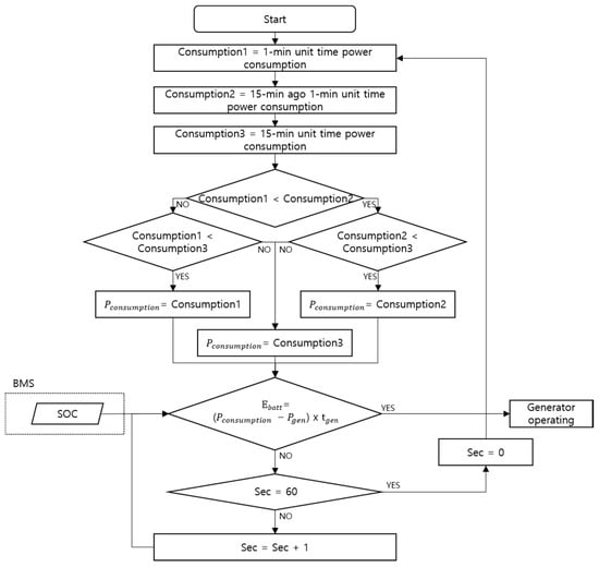
Figure 13.
Flowchart of the proposed algorithm.
7. Validation and Discussion
7.1. Configuration of Driving Cycle Based on Actual Driving Test
Figure 14 shows the driving cycles based on actual driving data, obtained through the actual driving tests. Driving cycles were configured with combination of acceleration driving, uphill driving and rough road driving, to verify the applicability of algorithms to various patterns of battery consumption. Cycles 1, 2 and 3 are composed of different combinations of data and are shown in Table 5.
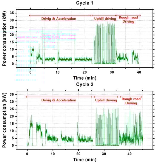
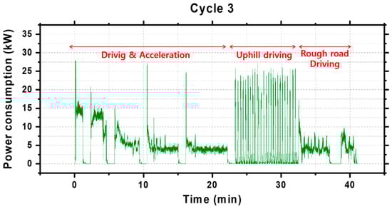
Figure 14.
Driving cycle based on actual driving data.
Table 5.
Configuration of driving cycles.
7.2. Results of Algorithm Application with Actual Driving Cycle Data
Based on the data obtained through an actual driving test, a simulation was performed by applying this data to the proposed algorithm. When Cycle 1 data was applied, the generator was operated late to maximize the benefits of the EV. In contrast, when Cycles 2 and 3 data were applied, the generator was operated early to utilize all the remaining fuel, as shown in Figure 15. Consequently, it was confirmed that the generator was operated based on the user’s power consumption trend, and therefore, the driving range was extended.
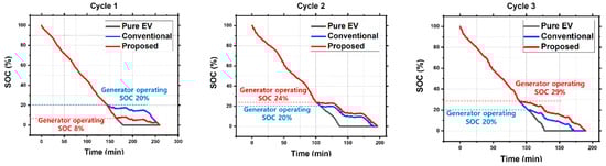
Figure 15.
Application of the proposed algorithm with actual measurement data.
7.3. Discussion and Application Limits
Although, many studies on hybrid EVs aim to minimize the use of fuel-based internal combustion engines; this paper aims that all the remaining fuel energy can be utilized. The proposed algorithm is designed with actual driving data collected from vehicle of similar specification to the systems we’ve configured. As a result, driving distance could be extended while maximizing the advantages of electric vehicles. However, it is not included that the power consumption data of other components besides driving. And since the results of the test could not have been verified with the generator installed, more research remains to be done on more actual test including components of configured system.
8. Conclusions
Re-EV technology supplements the short driving range of EVs. However, as Re-EVs have low power outputs owing to the use of a smaller generator compared with other hybrid vehicles, all its fuel might be used, and its battery can get completely discharged when the user consumes significant amount of power in short periods of time. However, if the generator operating point is flexibly determined according to the user’s power consumption trend, the remaining fuel can be used, thereby increasing the EV usability and fully utilizing the advantages of the EV:
- (1)
- To achieve the abovementioned objective, a method to flexibly determine the generator operating point was proposed by comparing the energy to be consumed and available energy in EVs.
- (2)
- The problems with the proposed algorithm were examined with different scenarios through simulation.
- (3)
- The problems with the proposed algorithm were analyzed based on actual driving tests.
- (4)
- The results were applied to the algorithm and power consumptions in 1-min and 15-min units were compared in triplicate.
- (5)
- The improved algorithm was applied to actual driving data via simulation and the corresponding results were obtained.
It should be noted that the approaches used in this study can also be applied to vehicles with different battery capacities or generator outputs. In nonlinear power consumption systems, the power consumption trend can be analyzed based on the SOC of the vehicle. As a future work, the performance of the proposed algorithm will be verified and optimized by constructing a Re-EV.
Author Contributions
Conceptualization and Investigation, D.-H.K.; Writing-Review & Editing, J.-H.H.; Project Administration, M.-H.H.; Supervision and Funding Acquisition, H.-R.C.; Conceptualization, G.-S.L.; Methodology, G.-S.L.; Software, G.-S.L.; Writing—original draft, G.-S.L.
Funding
This research was funded by the support of the Korea Institute of Industrial Technology as “Variable Architecture Powertrain Platform and Self-driving Factor Technology Development for Industrial EV Self-driving Vehicle” KITECH EO-19-0038.
Conflicts of Interest
The authors declare no conflict of interest.
Nomenclature
| Fuel energy [kWh] | |
| Available energy [kWh] | |
| Battery energy [kWh] | |
| Maximum Battery Energy [kWh] | |
| Energy to be consumed [kWh] | |
| Consumption power [kW] | |
| Generator output [kW] | |
| Generator operating time [h] | |
| Unit Time [h] | |
| Change in State of Charge [%] |
References
- Redelbach, M.; Özdemir, E.D.; Friedrich, H.E. Optimizion battery sizes of plug-in hybrid and extended range electric vehicles for different user types. Energy Policy 2014, 73, 158–168. [Google Scholar] [CrossRef]
- Cordiner, S.; Galeotti, M.; Mulone, V.; Nobile, M.; Rocco, V. Trip-based SOC management for a Plugin hybrid electric vehicle. Energy Policy 2016, 164, 891–905. [Google Scholar] [CrossRef]
- Tian, Y.; Xia, B.; Wang, M.; Sun, W.; Xu, Z. Comparision Study on Two Model-Based Adaptive Algorithms for SOC Estimation of Lithium-Ion Batteries in Electric Vehicles. Energies 2014, 7, 8446–8464. [Google Scholar] [CrossRef]
- Liu, H.; Wang, C.; Zhao, X.; Guo, C. An Adaptive-Equivalent Consumption Minimum Strategy for an Extended-Range Electric Bus Based on Target Driving Cycle Generation. Energies 2018, 11, 1805. [Google Scholar] [CrossRef]
- Xi, L.; Zhang, X.; Sun, C.; Wang, Z.; Hou, X.; Zhang, J. Intelligent Energy Management Control for Extended Range Electric Vehicles Based on Dynamic Programming and Neural Network. Energies 2017, 10, 1871. [Google Scholar] [CrossRef]
- Du, J.; Chen, J.; Song, Z.; Gao, M.; Ouyang, M. Design method of a power management strategy for variable battery capacities range-extended electric vehicles to improve energy efficiency and cost-effectiveness. Energy 2017, 121, 32–42. [Google Scholar] [CrossRef]
- Zhang, R.; Yao, E. Electric vehicles’ energy consumption estimation with real driving condition data. Transp. Res. Part D 2015, 41, 177–187. [Google Scholar] [CrossRef]
- Lee, D.H.; Kim, N.W.; Jeong, J.R.; Park, Y.I.; Cha, S.W. Component sizing and engine optimal operation line analysis for a plug-in hybrid electric transit bus. Int. J. Automot. Technol. 2013, 14, 459–469. [Google Scholar] [CrossRef]
- Peng, J.; He, H.; Xiong, R. Rule based energy management strategy for a series-parallel plug-in hybrid electric bus optimized by dynamic programming. Appl. Energy 2017, 185, 1633–1643. [Google Scholar] [CrossRef]
- Wang, B.; Xu, J.; Cao, B.; Ning, B. Adaptive mode switch strategy based on simulated annealing optimization of a multi-mode hybrid energy storage stytem for electric vehicles. Appl. Energy 2017, 194, 596–608. [Google Scholar] [CrossRef]
- Xu, L.; Zhang, J.; Liu, M.; Zhou, Z.; Liu, C. Control algorithm and energy management strategy for extended range electric tractors. Int. J. Agric. Biol. Eng. 2017, 10, 35–44. [Google Scholar]
- Chambon, P.; Curran, S.; Huff, S.; Love, L.; Post, B.; Wagner, R.; Jackson, R.; Green, J., Jr. Development of a range-extended electric vehicle powertrain for an integrated energy systems research printed utility vehicle. Appl. Energy 2017, 191, 99–110. [Google Scholar] [CrossRef]
- Schouten, N.J.; Salman, M.A.; Kheir, N.A. Energy management strategies for parallel hybrid vehicles using fuzzy logic. Control Eng. Pract. 2003, 11, 171–177. [Google Scholar] [CrossRef]
- Li, J.; Wang, Y.; Chen, J.; Zhang, X. Study on energy management strategy and dynamic modeling for auxiliary power units in range-extended electric vehicles. Appl. Energy 2017, 194, 363–375. [Google Scholar] [CrossRef]
- Chen, B.C.; Wu, Y.Y.; Tsai, H.C. Design and analysis of power management strategy for range extended electric vehicle using dynamic programming. Appl. Energy 2014, 113, 1764–1774. [Google Scholar] [CrossRef]
- Li, J.; Jin, X.; Xiong, R. Multi-objective optimization study of energy management strategy and economic analysis for a range-extened electric bus. Appl. Energy 2017, 194, 798–807. [Google Scholar] [CrossRef]
- Abdelgadir, A.A.; Alsawalhi, J.Y. Energy management optimization for an extended range electric vehicle. In Proceedings of the 2017 7th International Conference on Modeling, Simulation, and Applied Optimization (ICMSAO), Sharjah, Alian, 4–6 April 2017. [Google Scholar]
- Wirasingha, S.G.; Emadi, A. Classification and Review of Control Strategies for Plug-In Hybrid Electric Vehicles. IEEE Trans. Veh. Technol. 2011, 60, 111–122. [Google Scholar] [CrossRef]
- Nguyen, A.; Lauber, J.; Dambrine, M. Optimal control based algorithms for energy management of automotive power systems with battery/supercapacitor storage devices. Energy Convers. Manag. 2014, 87, 410–420. [Google Scholar] [CrossRef]
- Shabbir, W.; Evangelou, S.A. Real-time control strategy to maximize hybrid electric vehicle powertrain efficiency. Appl. Energy 2014, 135, 512–522. [Google Scholar] [CrossRef]
- Tate, E.D.; Harpster, M.O.; Savagian, P.J. The electrification of the automobile: From conventional hybrid, to plug-in hybrids, to extended-range electric vehicles. Citeseer 2008, 1, 156–166. [Google Scholar] [CrossRef]
- Liu, X.; Fan, Q.; Zheng, K.; Duan, J.; Wang, Y. Constant SOC control of a series hybrid electric vehicle with long driving range. In Proceedings of the IEEE International Conference on Information and Automation, Harbin, China, 20–23 June 2010. [Google Scholar]
- He, B.; Cheng, X.; Cao, G.; Xu, J.; Ouyang, M. Dynamic control for auxiliary power unit of series hybrid electric vehicles. Autom. Eng. 2006, 28, 12–16. [Google Scholar]
- Li, J.; Sun, F.; Zhang, C. Energy management strategy and real-time simulation of hybrid electric tracked vehicle. ACTA Armamentarill 2013, 34, 1345–1351. [Google Scholar] [CrossRef]
- Zhu, Y.; He, Y.; Zhou, L. Energy management strategy for a range-extended electric bus. Chin. J. Autom. Eng. 2013, 440–446. [Google Scholar]
- Zhang, S.; Xiong, R. Adaptive energy management of a plue-in hybrid electric vehicle based on driving patten recognition and dynamic programming. Appl. Energy 2015, 155, 68–78. [Google Scholar] [CrossRef]
- Xiang, C.; Ding, F.; Wang, W.; He, W. Energy management of a dual-mode power-split hybrid electric vehicle based on velocity prediction and nonlinear model predictive control. Appl. Energy 2017, 189, 640–653. [Google Scholar] [CrossRef]
- Liu, D.; Wang, Y.; Zhou, X.; Lv, Z. Extended range electric vehicle control strategy design and muti-objective optimization by genetic algorithm. In Proceedings of the 2013 Chinese Automation Congress, Changsha, China, 7–8 November 2013; pp. 11–16. [Google Scholar]
- Jin, L.Q.; Zeng, X.H.; Wang, W. The control strategy and cost analysis for series Plug-in hybrid electric vehicle. In Proceedings of the 2010 2nd International Conference on Advanced Computer Control, Shenyang, China, 27–29 March 2010; pp. 350–354. [Google Scholar]
© 2019 by the authors. Licensee MDPI, Basel, Switzerland. This article is an open access article distributed under the terms and conditions of the Creative Commons Attribution (CC BY) license (http://creativecommons.org/licenses/by/4.0/).