Article

Development of an Exergy-Rational Method and Optimum Control Algorithm for the Best Utilization of the Flue Gas Heat in Coal-Fired Power Plant Stacks †

Turkish Society of HVAC&R Engineers, Ankara 06680, Turkey
Submitted to the SDEWES Special Issue of Energies based on the conference paper “An Exergy-Based Optimum Control Algorithm for Rational Utilization of Waste Heat from the Flue Gas of Coal-Fired Power Plants” in the Proceedings of the 13th SDEWES Conference as underlined in the Acknowledgements.
Energies 2019, 12(4), 760; https://doi.org/10.3390/en12040760
Submission received: 8 January 2019 / Revised: 9 February 2019 / Accepted: 12 February 2019 / Published: 25 February 2019

Abstract

:
Waste heat that is available in the flue gas of power plant stacks is a potential source of useful thermal power. In reclaiming and utilizing this waste heat without compromising plant efficiency, stacks usually need to be equipped with forced-draught fans in order to compensate for the decrease in natural draught while stack gas is cooled. In addition, pumps are used to circulate the heat transfer fluid. All of these parasitic operations require electrical power. Electrical power has unit exergy of almost 1 W/W. On the contrary, the thermal power exergy that is claimed from the low-enthalpy flue gas has much lower unit exergy. Therefore, from an exergetic point of view, the additional electrical exergy that is required to drive pumps and fans must not exceed the thermal exergy claimed. Based on the First-Law of Thermodynamics, the net energy that is saved may be positive with an apparently high coefficient of performance; however, the same generally does not hold true for the Second-Law. This is a matter of determining the optimum amount of heat to be claimed and the most rational method of utilizing this heat for maximum net exergy gain from the process, under variable outdoor conditions and the plant operations. The four main methods were compared. These are (a) electricity generation by thermoelectric generators, electricity generation with an Organic-Rankine Cycle with (b) or without (c) a heat pump, and (d) the direct use of the thermal exergy that is gained in a district energy system. The comparison of these methods shows that exergy-rationality is the best for method (b). A new analytical optimization algorithm and the exergy-based optimum control strategy were developed, which determine the optimum pump flow rate of the heat recovery system and then calculate how much forced-draft fan power is required in the stack at dynamic operating conditions. Robust design metrics were established to maximize the net exergy gain, including an exergy-based coefficient of performance. Parametric studies indicate that the exergetic approach provides a better insight by showing that the amount of heat that can be optimally recovered is much different than the values given by classical economic and energy efficiency considerations. A case study was performed for method (d), which shows that, without any exergy rationality-based control algorithm and design method, the flue gas heat recovery may not be feasible in district energy systems or any other methods of utilization of the heat recovered. The study has implications in the field, since most of the waste heat recovery units in industrial applications, which are designed based on the First-Law of Thermodynamics, result in exergy loss instead of exergy gain, and are therefore responsible for more carbon dioxide emissions. These applications must be retrofitted with new exergy-based controllers for variable speed pumps and fans with optimally selected capacities.

1. Introduction

About two-thirds of the energy of the input fuel in conventional thermal power plants is wasted in stacks and cooling towers. Although, from environmental and health points of view, thermal power plants should be located relatively far from cities, in many developing countries, especially old coal-fired thermal power plants with quite low thermal efficiencies (even less than 30%) are located in close proximity to metropolitan cities, such as in New Delhi. Air pollution is a significant concern in these areas, including the Badarpur coal power plant [1]. For example, the air-quality index rose to 1010 on 8 November 2017 [2]. While the only reason for pollution is not the coal-fired power plants, the waste heat from these plants may be utilized in district energy systems to partly offset air pollution by substituting the need for thermal energy, like the heating of buildings, if the reclaimed heat from the power plants that can be delivered to the built environment is not small [3,4]. In typical coal-fired power plants, the condenser is run through an open-loop water circuit while using river water. Although river water is returned to the river without much loss, the water temperature is substantially increased. Flue combustion gases are rejected through a stack. Other industries that have the potential for waste heat recovery in their stacks, in addition to thermal power plants, include the textile industry [5]. In other studies, flue gas heat recovery is found to be beneficial, especially in high-moisture coals that are based on the First-Law of Thermodynamics [6]. The same type of approach is applicable to studies regarding pressurized pulverized coal combustion [7].
Findings that lead to an indication of environmental and economic benefits are mostly based on energy savings. Researchers have also looked into exergy analyses, but almost all of the research was limited to the component basis in order to determine the major exergy destruction points and the overall exergy efficiency [8]. Kaushik et al. [9] determined that the exergy analyses were used to determine the components with the greatest exergy destruction, especially the boiler in coal-based thermal power plants. Heat recovery steam generators and flue gas exhausts to the stack were the focus of other analyses, e.g., [10]. In a typical coal-fired power plant, almost two-thirds of the energy of the coal that is consumed is wasted in the form of heat [11]. In Figure 1, the combined-cycle thermal power plant with a bottoming cycle, which is shown in inset (a) generates only power and all of the waste heat is rejected by some means to the environment, mostly by cooling towers to the atmosphere, which also wastes water. This conflicts with the environment, energy, and water nexus needs of today’s world [12]. In inset (b) of Figure 1, however, a part of the heat in the flue gas is recovered in the stack. Condenser heat may also be reclaimed in this process, which reduces the need and the size of the cooling towers. However, if the flue gas is cooled too much in the heat recovery process, then the natural draught in the stack decreases to a point that a draught fan might be needed, which consumes electrical energy. The difference between the unit exergies of electric power and reclaimed thermal power is an important performance metric, which is often ignored. The reclaimed heat then may be utilized in a district heating loop, in addition to the power that is delivered to the customers.
According to EU/2004/8/EC [13], because heat is delivered to customers that are located outside in a metered and useful manner, such a plant qualifies as a cogeneration plant (CHP). According to the same Directive, this plant may qualify for a high-efficiency plant if such a plant results in at least 10% fuel savings in terms of Primary Energy Savings Ratio (PES). However, the district heating system needs a pumping station (PS) in the district in order to circulate the heating water in the district loop and a heat exchanger (HE) at the interface of the two closed thermal loops, namely D and P. To recover the heat from the flue gas (in loop P) a pumping system is required. Exergy is gained in the form of heat, but at the same time, exergy is required in the pumps, which is mostly driven by electric power. If the exergy gain in the heat recovery process is less than the exergy demand of the draught fan and circulating pumps, then this system will not contribute from an exergy rationality point of view. The amount of heat that may be recovered has an optimum value, which depends on the stack height (H). The stack height may be chosen to be higher during the design stage of the power plant instead of installing a fan to the stack. Yet, this requires embedded exergy of additional material and additional construction work for the stack. This requires a careful optimization for the stack height. Stack height, H, is crucial both in the performance of the power plant and waste heat recovery. In thermal power plants, especially if coal is used, then H may be quite high in order to keep the pollutants elevated enough in the atmosphere. Therefore, H in meters is also a function of the pollutant (Sulfur) content. Today, in large thermal power plants, the stack height may reach up to 150 m. The minimum stack height is calculated by the following equation in the literature:
H 4.33 ( F S ) 0.3
In Equation (1), 4.33 is a factor of the rule of thumb in order to assure sufficient natural draught, PD (Also see Equation (12) in Section 2.6.2), F is the coal consumption rate in kg per hour, and S is the Sulphur content in the percentages of the coal used. If, for example, a thermal power plant consumes 40 ton (40,000 kg) per hour of coal with 0.4% Sulphur content, then the necessary stack height will be 79 m.
There are four main methods that are available in the literature for utilizing the thermal power exergy claimed along the stack height, once it is reclaimed from the flue gas. These methods, which appear in the literature, may be grouped in the following manner, as will be compared later in the manuscript:
(a) electricity generation by Thermo-electric generator (TEG) arrays [14,15],
(b) electricity generation by an Organic-Rankine Cycle (ORC) without a heat pump [16,17],
(c) electricity generation by ORC turbines with a heat pump [18,19], and
(d) direct utilization of the thermal exergy in the stack in a district energy system [20,21].
In all of the above methods (a)–(d), the forced-draught fan in the stack and fluid circulation pumps are necessary for claiming the thermal power exergy, in addition to the power conversion equipment. If, for all models, the thermal energy claimed is fixed (100 kW in following methods) and the flue gas inlet temperature is the same for all models, then the forced-draught fan power demand is the same, but the circulation pump power demand changes, depending upon the equipment that is used in each model.

Aims of the Research Work

The main objective of this research is to first close the gap in the literature by a new model concerning the missing investigation of exergy rationality regarding the industrial waste heat utilization with parasitic losses. In so-doing, the study compares the different specific methods of utilizing the heat that is available in the flue gas of coal-fired thermal power plant stacks by developing exergy-based new metrics and a control algorithm in order to maximize the benefits of utilizing such waste heat in the industry and the built environment. Each method was analyzed in terms of the First and Second-Law efficiency, the coefficient of performance (COP), and exergy-based COP (COPEX) prior to the analysis of a case study for the selected methods.

2. Materials and Methods

Waste heat recovery from hot flue gas flowing across the stacks of power plants have a wide potential, but such systems must be exergetically investigated, designed, and controlled in order to achieve a net positive exergy gain and net-negative carbon dioxide (CO2) emissions responsibility in practice. The comparison of the methods (a) to (d) is provided in the following.

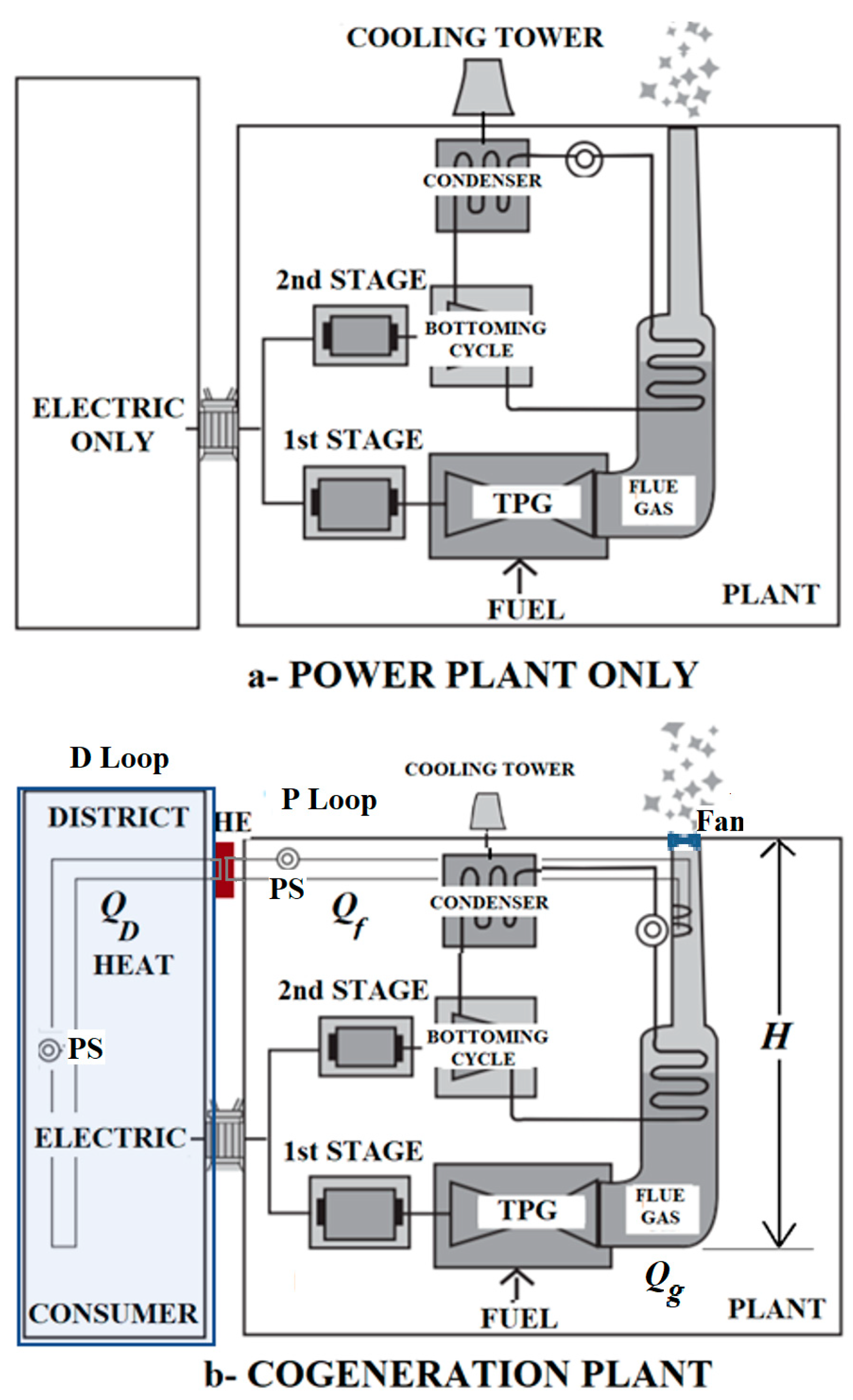
2.1. Method (a): Power and Heat Generation with Thermoelectric Generators

Oswaldo et al. [14] presented the design and development of a new solid-state TEG using thermoelectric modules for the experimental analysis of the technical viability for the uses of waste heat in industrial processes, like forging, hot rolling, industrial refrigeration systems, boilers, and ceramic kilns for a maximum temperature gradient of 1073 K. Their prototype test results that were based on the First-Law of Thermodynamics showed the feasibility of TEGs in reclaiming the industrial waste heat. However, the study did not directly consider the Second-Law and the parasitic exergy demand due to the use of a cooling circuit with electrically driven pump. Memon and Khawaja [15] have also developed a direct heat harvesting method while using a hot plate with heat-stove TEG for electrical performance testing. They acknowledged the presence of electric power demand for cooling the TEG units by forced-air circulation. Yet, their analysis did not address the exergy difference between the thermal exergy that was reclaimed and the electrical power exergy.
In this context, the use of an array of TEG modules facing the flue gas in the stack that are externally cooled by a hydronic circuit with a pump is depicted in Figure 2 for further analysis in this study. The heat that is recovered by the cooling circuit and the electric power that are generated by the TEG array are to be connected to external loads. The arrangement in Figure 2 comprises method (a).
According to Figure 2, 8 kW of electrical power is generated by the TEG array that has a First-Law efficiency of 0.08. This amount is, at the same time, the amount of electrical power exergy because the unit exergy of electricity is virtually 1 kW/1 kW. Heat from the back side of TEG array is reclaimed by a hydronic circuit and heat exchangers, with an efficiency of 0.55 by using pump(s), which demand 5 kW of electric power (including stack fan power demand), while 100 kW of thermal power at 700 K drives the system. An additional draught fan compensates for the natural draft loss due to the cooling of the flue gas. The Second-Law efficiency is 0.11, while the First-Law efficiency is 0.60 and the COP is 12.6. Such a relatively high COP leads to the impression that such a system is beneficial and techno-economically attractive. Yet, if COP is re-defined in terms of exergy (Equation (2)), namely COPEX, then the exergo-environmental properties of the model changes substantially.
C O P E X = Net   Exergy   Gain Total   Exergy   Input = 8   kW + 3.4   kW 5   kW 58   kW + 5   kW = 0.10

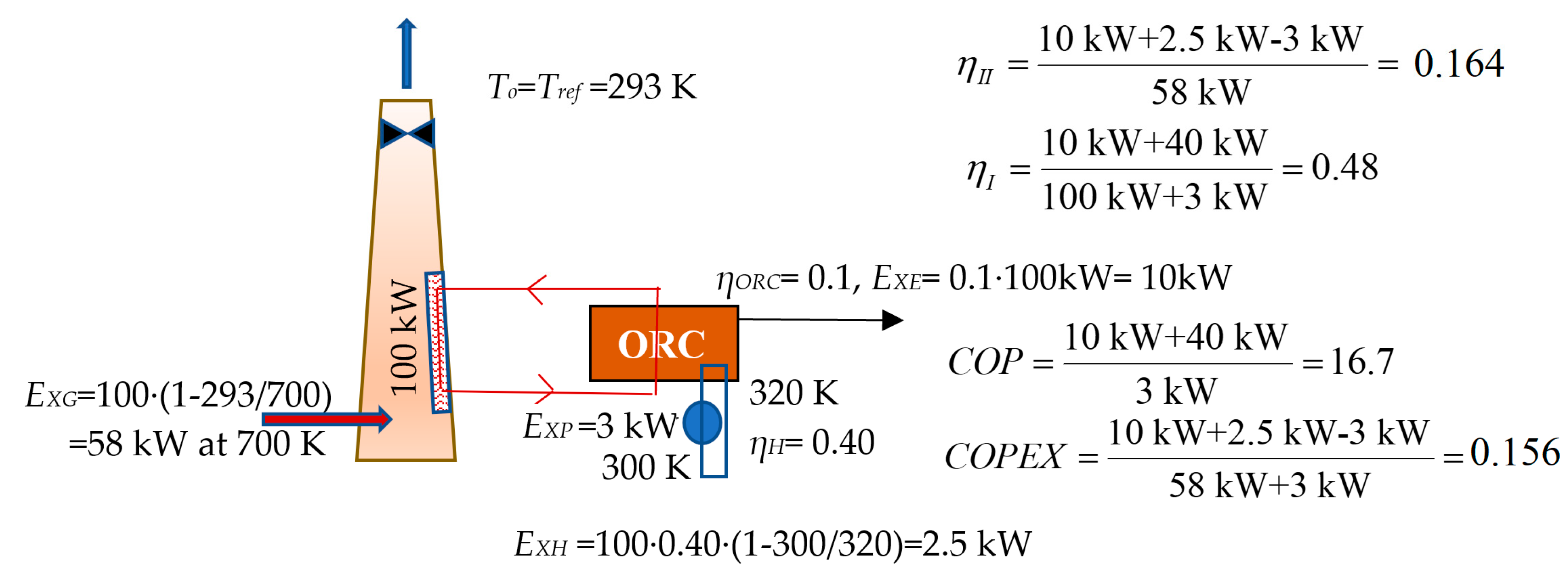
2.2. Method (b): Power Generation with Organic Rankine Cycle Turbines

Another method that is investigated in the literature is driving an ORC turbine after reclaiming the heat of the flue gas and transporting it to the external of the stack. A low-temperature external load through a hydronic circuit that is driven by a pump cools the ORC. The electric power that is generated by ORC turbines depends upon the source temperature while the First-Law efficiency is around 10%. Lecompte et al. [16] applied ORC technology to an electric arc furnace with a First-Law efficiency of about 13%. This efficiency is higher when compared to other lower source temperature applications. Another study investigated the technical aspects of modular ORC systems over a broad range of heat source temperatures with different working fluids [17]. A payback period that was slightly less than five years was predicted at a source temperature of around 700 K based on the First-Law and economic benefits of ORC systems. The principle of this method (b), as modeled in this study, is extended in Figure 3.

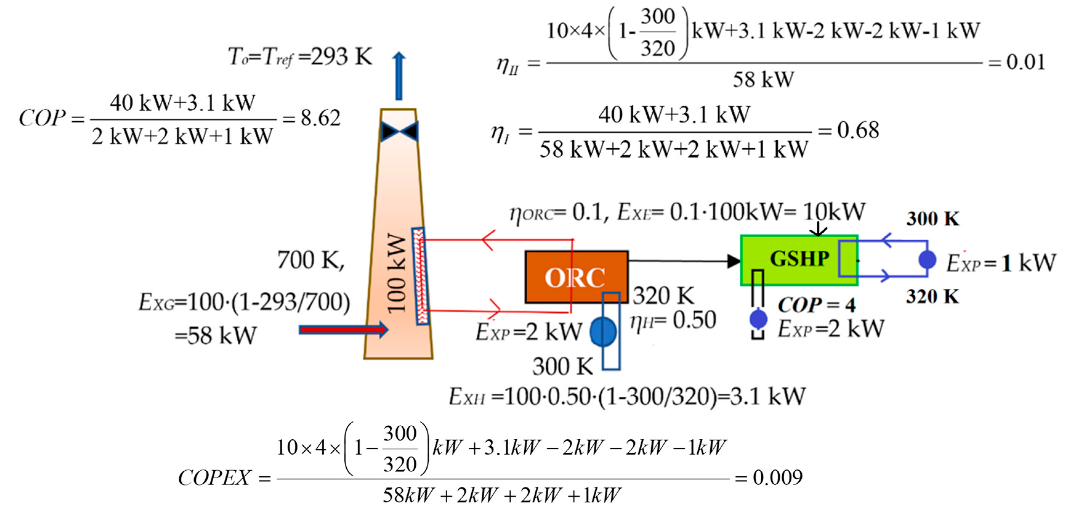
2.3. Method (c): Power Generation with Organic Rankine Cycle and then Converting to Heat by a Heat Pump

By converting electric power to thermal power with a COP greater than 1, a heat pump may be tailored to the ORC, depending upon the dominant load on the demand side. This method (c) is shown in Figure 4. Re-converting claimed power exergy to thermal power exergy even with a COP, of 4.0 in this case, is not rational. For a break-even condition, the COP of the heat pump needs to be 1/(1 − 300 K/320 K) = 16, which is practically not possible in the field with today’s technology. This indicates that several heat recovery systems may not be exergetically rational and practical while they are responsible for more CO2 emissions than saved. This gap is also evident in the study of He et al. [18], in which the feasibility of reclaiming additional electrical power from the waste heat of a fuel cell by an ORC system coupled with a heat pump was investigated, thus establishing a bottoming cycle. This study claimed that, at an optimum operating temperature, the results are favorable according to the First-Law. Among the few studies that involved the exergy concept in the evaluation of medium-temperature heat recovery from industrial gases with ORC technology and CO2 transcritical cycles, Ayachi et al. [19] have presented their pinch analysis for source temperatures between 438 K and 420 K. However, the case was only taken in a pinch problem domain.

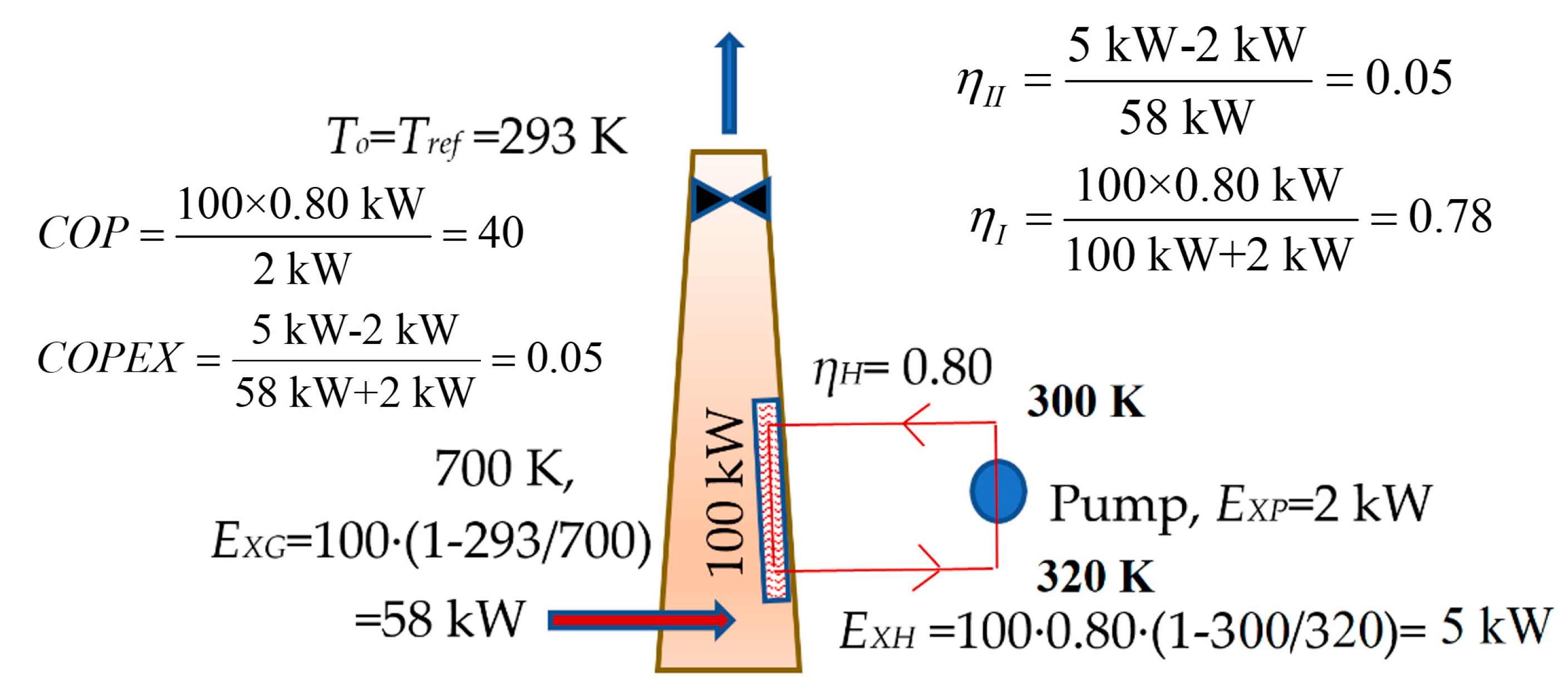
2.4. Method (d): Direct use of the Thermal Exergy in ae District Energy System

Especially when a district energy system is close-by, waste heat from power plants gains additional importance. One method is to recover heat directly from the flue gas. Based on the First-Law, Xu et al. [20] had considered reclaiming heat from the ventilating air methane in a hot-air power generator. The authors had concluded that the overall system efficiency for a decarbonizing process with a hot air power generator reached 27.1%, which is better than the standalone reference systems. The arrangement of tube banks in the stack needs careful investigation. A horizontal tube or an inclined tube bank occupying the whole cross-sectional area of the stack may be effective but reduces the natural draft. Tube banks that are attached to the stack walls, which leave a large portion of the cross section free for the gas flow, may be preferable, but a careful case-by-case analysis needs to be conducted. In this aspect only, Erguvan and MacPhee [21] had performed energy and exergy analyses for several tube bank configurations in waste heat recovery applications. The method of direct heat recovery from the flue gas is depicted in Figure 5 with the relevant exergy formulations.

2.5. The Necessity for an Exergy-Based Model

There is a necessity for developing an exergy-based model for a thorough comparison of methods (a) to (d). In addition, the heat that is optimally recovered at the stack(s) of a large power plant, Qf, may be utilized in a district energy system. In this case, the distance between the power plant and the district, L, which is subject to the condition L < Lmax, where Lmax is the maximum distance, should be exergetically rational as well as the exergy that is demanded by the pumping stations, EXPS. Exergy rationality for both of the loops is defined in Equations (3) and (4).
Q D ( 1 T D o T D i ) > E X P S          ( Condition   1 )
Q f ( 1 T f o T f i ) > ( E X C P + E X F )       ( Condition   2 )

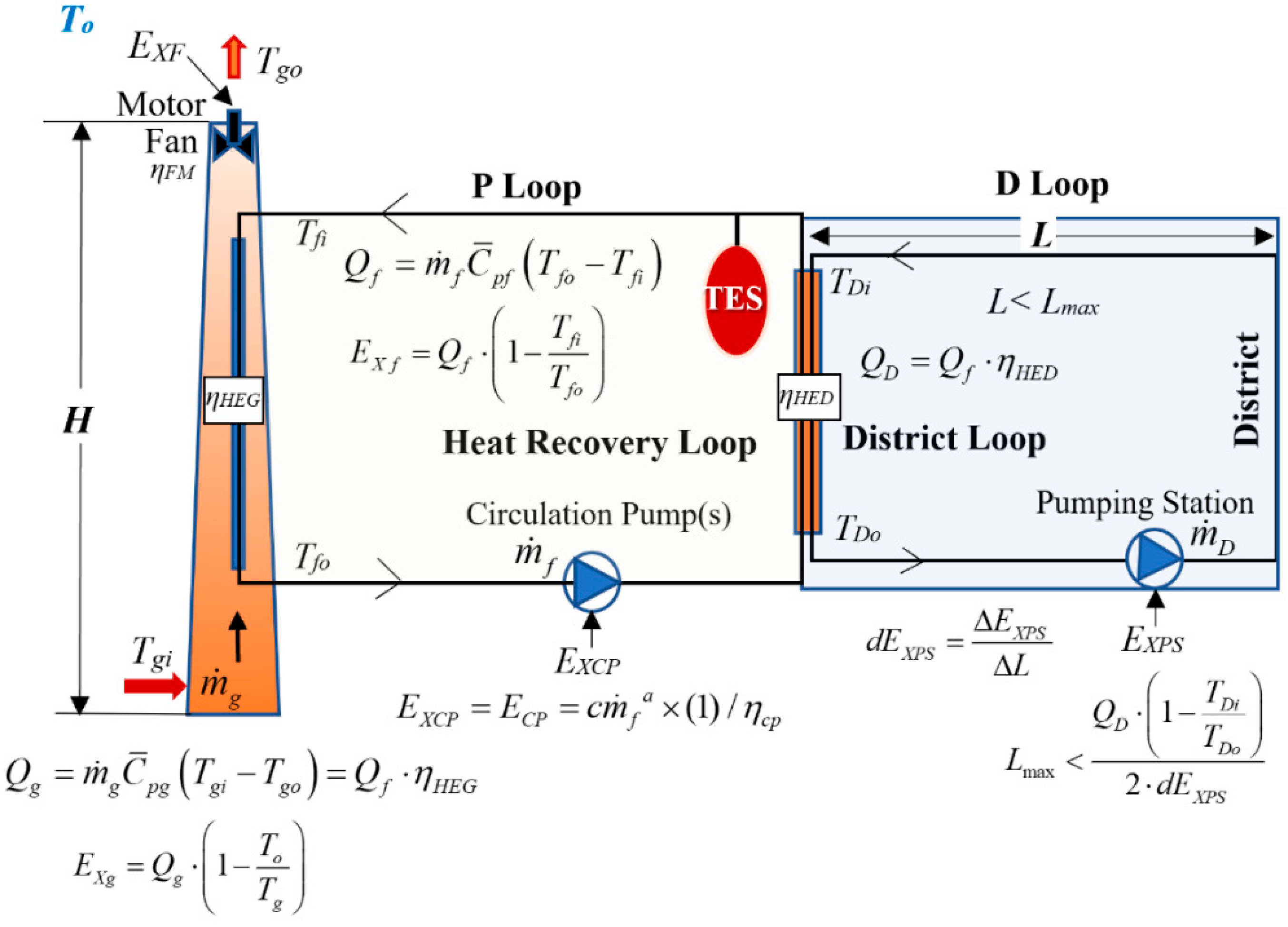
2.6. Characterization of the District Energy Model

Figure 6 shows the new model, which enables the user to analyze several design parameters and environmental conditions, along with plant performance variables that are related to the stack. Performance constants, namely (c) and (a) regarding the exergy demand, EXCP of the circulation pump mainly depend upon the circuit length, pump type, and piping material and size. In the case study to be shown later in this paper, these terms are assumed to be 15 and 0.3, respectively. Figure 7 then shows the exergy flow bar for a typical heat recovery process, where the average temperature of the flue gas is 700 K. The heat recovery loop (P loop) operates between 313 K and 363 K, the average outdoor temperature in the summer To (also, the reference temperature, Tref), which renders a critical draft condition as compared to the winter at 293 K. Subsequently, one of the metrics of the Rational Exergy Management Model (REMM) as the REMM Efficiency, ψR [22], as provided in Equation (5), is 0.24 [23]. This is a similar value with a solar water heater system, since the major unit exergy destruction is prior to the heat recovery, and only a low-enthalpy heat is recovered without power generation upstream, like ORC.
ψ R = ε d e m ε sup = ( 1 313 363 ) ( 1 293 700 ) = 0.24
Although the waste heat recovery might seem to be economically beneficial and environmentally useful, if the exergy of the electrical energy that is used for the draught fan, along with pumping and driving other ancillary devices, is higher than the recovered lower exergy-heat, then the system will not contribute to the economy and the environment at large.

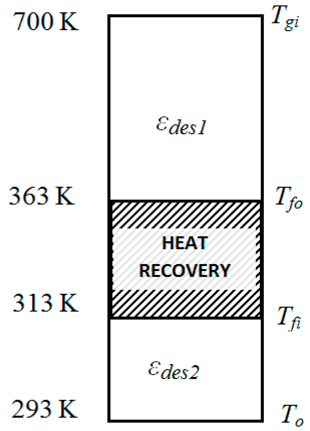
2.6.1. Circuit P Loop: Exergy-based Optimum Heat Recovery Drive Unit for Industrial Stacks

This condition may be expressed by the objective function in Equation (6), which represents the net exergy gain in this circuit. The net exergy gain, EXNET must be maximized by minimizing EXF and EXCP while exergy of Exf is claimed from the flue gas. If the district energy system is integrated, then ExD replaces Exf and EXPS is introduced (Equation (7)). In certain cases, the reduction of the size of the cooling tower due to the conversion of waste heat rejection to useful heat in the stack may be substantial. Subsequently, an exergy saving term that is associated with the reduction of ancillary power demand of the cooling towers may be added to the right-hand side of the other original formulations for this research work, as given below (Equations (7)–(11)). In Equation (10), the specific heat needs to be calculated at the average fluid temperature. In Equation (11), the coefficient c and the exponent a are approximated coefficients for the pump characteristics.
E X N E T = E x f E X F E X C P       ( Maximize )
E X N E T = E x D E X F E X C P E X P S
E X f = Q f ε f
ε f = ( 1 T f i T f o )
Q f = m ˙ f C ¯ p f ρ f ( T f o T f i )
E X C P = c m ˙ f a × ( 1 ) / η c p = E C P

2.6.2. Natural Draught Pressure and EXF

Since heat is drawn from the hot flue gas in the stack, the flue gas cools down and the average flue gas temperature in the stack Tg reduces, which reduces the natural draught pressure (PD). Equation (12) shows the relationship between Tg and PD [24]. According to this equation, draught decreases with a decrease in the average flue gas temperature. At a given time t, the change in the draught pressure, ΔPD, only depends on the amount of decrease in ΔTg if some heat is recovered from the flue gas, as given in Equation (14).
P D = C P a t m H ( 1 T o 1 T g ) = C ( 1 T o 1 T g )       ( kPa )
where,
T g T g i n + T g o 2
Δ P D = ( C T g 2 ) Δ T g         ( kPa )
where,
CA constant for coal-fired plant stacks, 0.0342 K·m−1
C′C·Patm·H
PatmAtmospheric pressure at the given elevation at the given time, kPa
HStack height, m
TgAverage flue gas temperature in the stack, K
TgiHot flue gas entry temperature to the stack, K
TgoFlue gas exit temperature from the stack, K.
In order to resume the original natural draught, the installation of a new hot-gas type industrial forced-draught fan in the stack or oversizing, an existing one will be necessary. For new power plants with flue gas heat recovery, the stack height may be selected higher in order to avoid a fan, but in this case, the embodiment recovery of energy and exergy of the extra stack material and construction must be considered against energy and exergy savings by the associated heat recovery. The motors of these fans may operate on on-site power in a thermal power plant. Especially, if the power plant is a combined-cycle plant, the average power generation efficiency is about 0.52 in Europe [13]. For other industrial plants, like in the textile industry, electricity is mostly received from the grid. The average efficiency of grid-feeding power plants, especially in developing countries, is about 30% or even less. This efficiency, when coupled with transmission and transformation losses, makes the case even worse based on the total CO2 emissions responsibility in a broader perspective if the fuel mix mainly consists of fossil fuels [25]. This additional CO2 emissions responsibility in terms of the equivalent useful heat that is to be lost in a typical thermal power plant also needs to be considered in the calculations if the grid power is used in the heat recovery system. The draught fan simultaneously needs to maintain the original m ˙ g , which is given by Equation (15) [24].
m ˙ g = 0.65 A ¯ g 2 g H ( 1 [ T o T g ] )       ( m 3 / s )
Equation (15) takes the molar mass of the flue gas and the outside air as equal, and the frictional resistance and heat losses in the stack walls and any heat exchanger inside the stack to be negligible. Here, A ¯ g is the average cross-sectional area of the stack, in the unit of m2, along with stack height (H). On the other hand, if Tg decreases, then m ˙ g also decreases:
Δ m ˙ g = 0.65 A ¯ g 2 2 g H ( 1 T o T g ) ( T o T g 2 ) Δ T g       ( m 3 / s )
Therefore, while the draught fan needs to compensate for both the decreases in the gas flow rate and the decrease in the draught pressure, the required fan power, EF (almost equal to fan exergy demand), at a given electric motor and fan efficiency of ηFM will consist of the product of ΔPD and Δ m ˙ g , as given in Equation (17).
E F = E X F = Δ P D Δ m ˙ g η F M       ( kW )

2.7. Rating Metrics

Four metrics were identified for rating the performance of waste heat recovery from the flue gas. These metrics may be related to CO2 emissions responsibility, energy efficiency, and exergy efficiency.

2.7.1. Performance Coefficients

The metrics that are related to performance coefficients are given in Equations (18)–(20). In Equation (18), the exergy-based coefficient of performance (COPEX) is a product of the COP and the unit exergy gain from waste heat recovery, Δεf. Usually, the unit exergy gain, namely (1 − Tfi/Tfo), is small. Therefore, COPEX will be far less than one, if a proper design recovery system is installed and the fluid flow rate is not dynamically controlled with an exergy-based control algorithm and a frequency-controlled electric motor for the circulation pump. This means that the heat recovery system is not rational. For example, if these temperatures are 300 K and 360 K, respectively, then the unit exergy of the fluid at the supply point, Δεf is only 0.167 W/W. From Equation (18), the traditional COP value of the recovery system must be greater than 6 in order to satisfy the condition of COPEX approaching one. This condition imposes strong design constraints on EXF and EXCP. This is an early indication regarding the importance and relevance of the Second-Law of Thermodynamics before attempting an economic and environmental analysis about waste heat recovery from the flue gas. A similar discussion of the author outside the context of waste heat recovery from flue gas is also valid for ground-source heat pumps [26]. In this case the heat pump only consumes electrical energy and provides thermal energy. Then:
C O P E X = C O P Δ ε f = C O P × ( 1 T f i T f o )       ( C O P E X 1 )
C O P E X = E X N E T E X F + E X C P
C O P = Q E X F + E X C P         ( C O P > 1 )

2.7.2. Fuel Savings

The exergy-based Primary Energy Savings Ratio, PESR, in percentage is based on 1 W of power generation. The original PES term in EU/2004/8/EC [13] was modified by the REMM model [25,27]. In Equation (21), CHPEη is a known value (power generation efficiency) for the given plant at design conditions [27]. The term 0.73 corresponds to (1 − ψRref), which is related to the reference value of (1 − 0.27) for the on-site CHP applications. The values 0.52 and 0.80 are the reference efficiencies for separate power and heat generation, respectively [13], based on 1 W of power generation.
P E S R = ( 1 1 ( [ C H P E η ( 1 0.52 + Q f 0.80 ) ] 0.73 ( 1 ψ R ) ) ) × 100

2.7.3. Carbon Dioxide Emissions Replacement

The third metric is related to the CO2 emission replacement rate. The CO2 emissions savings rate (kg CO2/s) that is attributable to net exergy recovery, EXNET, from the flue gas for a pulverized coal power plant with coal properties of adiabatic flame temperature of 2850 K and 30,000 kJ/kg lower heating value (LHV) with no condensation in the stack and the wet coal input, as well as the CO2 content of 3.6 kg CO2/kg coal, was derived, which is given in Equation (22) [28,29]:
C ˙ O 2 = E X N E T × 1.7 10 4

2.7.4. Thermal Efficiencies

As the fourth metric, the First-Law and Second-Law efficiencies, ηI and ηII, may be monitored for the rating and evaluation of the system, as given in Equations (23) and (24).
η I = Q f Q g + E C P
η I I = E X f E X C P E X g

3. Results

Table 1 compares methods (a) to (d) with source exergy at 58 kW prior to the selection of a method. As observed from Table 1, method (d) has the highest thermal efficiency (ηI) and the second highest COP, ηII and COPEX. Other methods have greater inconsistencies. Method (d) delivers heat at 340 K in this example, which is sufficiently high for district energy systems and it may also be used in absorption/adsorption cooling equipment. Provided that the distance between the plant and the district is not too far, method (d) is selected as a feasible option for practical applications. In the case study, a coal-based thermal power plant is going to be retrofitted with a flue gas heat recovery system. The design inputs and conditions are given in Table 2. The equations that are given in the method may be expressed in terms of the fluid (water) flow rate, m ˙ f . Thus, by introducing the flow rate m ˙ f , in all terms, then taking a derivative, and equating it to zero to find the optimum flow rate. Equation (5) may be maximized. This will be a time-dependent solution in terms of all time-dependent variables that either depend on atmospheric conditions and part-load conditions, like Tg, m ˙ g , To, Tfo, Tfi, and variables that are related to the D Loop, as identified in previous Figure 6.

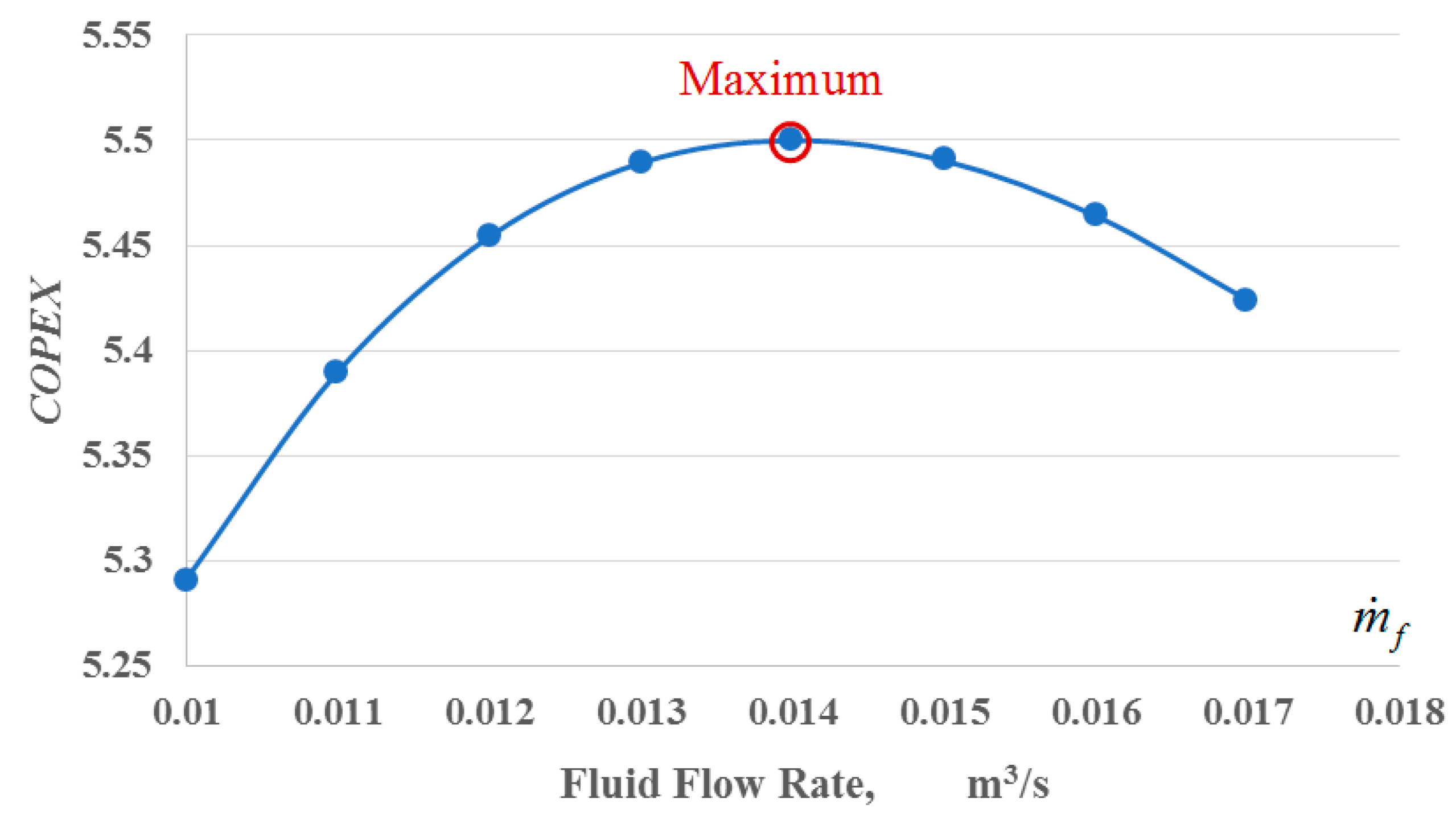
3.1. Results of the Analysis of the P Loop-Case Sdudy

In this study, a step-by-step solution is introduced, where the flow rate is changed incrementally to find the optimum point, which is subjected to the condition that the flue gas outlet temperature is not lower than the condensation temperature, Tgc, which is often taken at 420 K for coal combustion and low Sulfur content fuel oils [30]. Reducing the temperature of the flue gas in the stack may be associated with other adverse phenomena. It is very important that the minimum flue gas temperature is maintained and not violated in order to prevent the acid dew point from being reached. Figure 8 shows the results for the given initial and operating conditions. According to Figure 8 with a flue gas temperature of 600 K, there is an optimum fluid flow rate, which maximizes the net exergy gain from the flue gas. However, for certain cases of design and operational variables, an optimum fluid flow rate may not be found. In such a case, the solution approaches either the lowest flow rate or the highest flow rate, within an economical range. The variation of the maximum ENET points for different outdoor-air temperatures when the fluid flow rate is fixed at each optimum point is shown in Figure 9. According to Figure 9, ENET decreases with an increase in the outdoor-air temperature. If the inlet temperature of the flue gas is 500 K instead of 600 K, then COPEX decreases below the threshold value of one and the optimum solution for the fluid flow rate approaches the lower bound, which is shown in Figure 10.
According to Figure 10, the maximum COPEX that is possible is just one at the lowest flow rate, which means that the exergy that is gained by the circulating fluid is equaled to the total exergy demand of the parasitic equipment, such as the stack fan and the circulating pump. In other words, the net exergy gain is zero. These results show that the performance is highly sensitive to the flue gas inlet temperature, outdoor temperature, and the flow rate of the fluid in the P loop. Therefore, the circulation pump must be dynamically and digitally controlled to maintain COPEX as greater than one. There may be cases when the heat recovery system needs to be stopped. The solution starts with a minimum fluid flow rate and the temperature decrease in the flue gas in the stack is calculated first (see Equation (25)). Subsequently, the other performance variables are calculated, as provided in Table 3.
T g o = T g i ( m ˙ f m ˙ g ) ( C p f C p g ) ( ρ f ρ g ) ( T f o T f i )

3.2. Implications of the Analysis for the D Loop

The heat recovered at the stack(s) of a large power plant, Qf may be utilized in a district energy system. Such a D Loop, as identified in the previous Figure 6, should also consider the distance between the power plant and the district L, which is subject to the condition LLmax and the exergy that is demanded by the pumping stations, EXPS. Exergy rationality for this condition is defined in Equation (26):
Q D ( 1 T D o u t T D i n ) > E X P S
where,
Q D = Q f η H E D
The exergy demand of power stations in the district circuit is a function of QD for a given ΔT in the circuit, which is typically 20 K at the design conditions in district heating. The constant term ao in Equation (29) is an empirical value, which is 0.6 km. In Equation (30), n depends upon the exergy of district heating supply in terms of Tdo. The value of Tref is 283.15 K (the average ground temperature in winter). 333.15 K represents a traditional district heating supply fluid temperature of 60 °C.
Δ T = ( T D i n T D o )
L L max = a o + ( Q D 1000 ) n × ( Δ T 20 ) 1.3       ( Q D > 1000   kW · h ,   Δ T 30   ° C )
n = 0.6 × ( ( 1 T r e f T D o ) ( 1 T r e f 333.15 ) ) ( 1 / 3 )
T D o = T f o Δ T H E D
T f o = T g o Δ T H E G
The typical temperature drop in the heat exchangers in a district energy system is targeted for 2.5 K each. Therefore:
T D o T g o 5   K
d E X P S = Δ E X P S Δ L
L max < Q D ( 1 T D i T D o ) 2 d E X P S

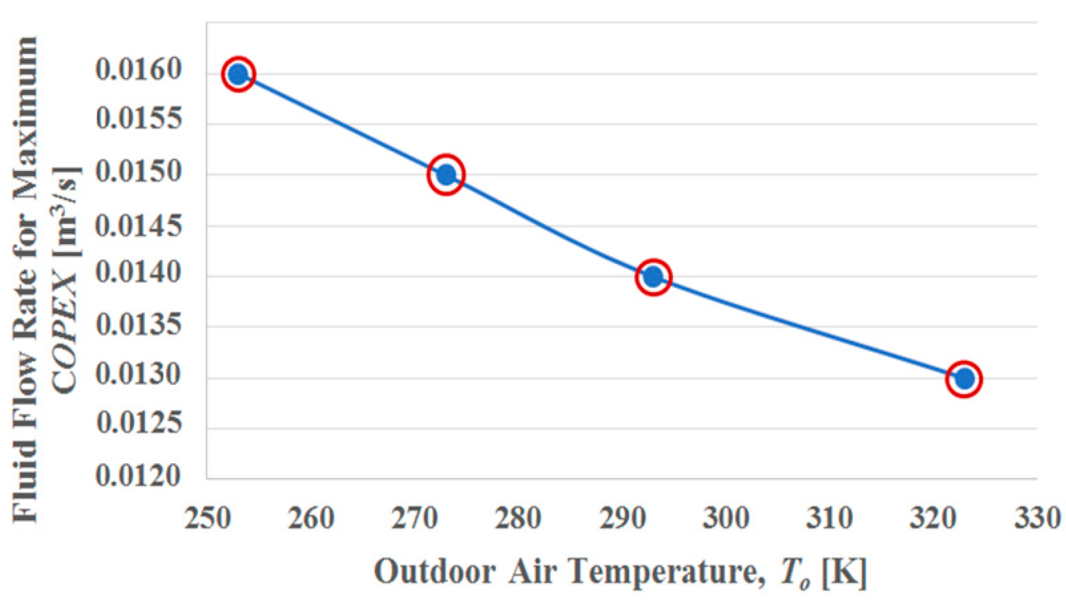
3.3. Development of the Control Unit to Maximize the Exergy Gain

The maximization of the net exergy gain and COPEX is related to the flow rate of the fluid through the circulating pump in the P loop first. All of the relevant inputs are gathered every five minutes and then processed for the optimum flow rate for this given time increment. The processed information for the optimum flow rate is fed to the driver of the variable-speed pump. The optimum pump speed is then checked for condensation of the flue gas in the stack (Tgo > Tgc) and the pump capacity. The flue gas temperature entering the stack fan is also checked against the temperature resistance of the fan. Efficiency changes in the heat exchangers are purposefully ignored. Figure 11 shows a simple flowchart of the process. If the thermal demand on the district side is lower than the optimum heat output at the same time interval, and then the surplus heat is stored in a thermal storage system (TES) before the necessary amount is sent to the district through a heat exchanger.
The data that is collected along with pollution variables, like the CO2 concentration and the sulfur content, is quite crucial in monitoring the environmental impact of all industrial installations on an instantaneous basis. Thermal power plants are not an exception as a major player in global warming. Therefore, such performance and control data that is available in thermal power plants may be incorporated into a central Internet-based control center and the data re-processed for a national or even global scale to optimize not all the thermal power plants, but also all of the industrial installations. This will then complete the exergy economy loop, which is very important for decoupling sustainable growth from CO2 emissions [31].

4. Conclusions

Waste heat recovery from the flue gas in thermal power plant stacks are important from environmental and economical points of view, especially in developing countries, where the plant efficiencies are low and mostly in relatively close vicinity of urban areas. This provides the opportunity for replacing some CO2 emissions in the urban area if the recovered heat is distributed in the form of a district heating system. However, there are certain challenges, one of the most important of which is that the design of such recovery systems need to be based on the Second-Law of Thermodynamics due to the fact that the unit exergy of the heat that is claimed is much lower than the unit exergy of electricity that is used to drive the related ancillaries and installed draught fan to the stack. In this respect, the minimum COP of the heat recovery system, on average, has to be 6.0. This poses serious challenges for the design of the gas-to-water type of heat exchangers. This study has shown that, not only in a poor design, but also at any time during the operation, the net exergy gain may be negative (COPEX < 1), because the exergetic performance is very sensitive to operational and climatological conditions. The case study has further exemplified this possibility, such that COPEX may become less than one any time, even with incremental variations in the dynamic conditions. In order to avoid this risk, a complete analytical model was presented, which enables the analysis of such a system in terms of the optimum water flow rate in the closed heat reclaiming circuit for the maximum exergetic coefficient of performance at given outdoor and operating conditions of the power plant.
In plant retrofits for this purpose, however, the stack should not be replaced with a new one with a new heat exchanger inside. Instead, the original stack must be retrofitted with minimal work. In fact, this is the second challenge. In order to avoid this challenge on a large-scale plant, the heat recovery unit may be a separate unit before the stack. However, this will disturb the original design performance of the stack and a larger fan might be needed in addition to other ancillaries that are related to the separate heat recovery unit. A cassette type heat exchanger or heat exchangers may be inserted at different levels of the stack with minimum invasion and minimum disturbance to the flow [32,33]. There are other studies in the literature, which bring the heat source to condensation temperature and then remove the moisture and recover more heat [34]. However, a similar approach will increase the exergy demand of the fan system to discharge the flue gas, since there will be almost no natural draught left in the remaining voyage of the flue gas. Under all of these considerations, the model that is developed in this study addresses multiple challenges and promises optimal heat recovery controls. Case study and performance calculations regarding four methods showed that the definition of COP is limited to economic evaluations while the “ambient, free” resources like air, sea water, and ground are ignored. In fact, especially when waste heat in the industry is considered, the waste heat needs to be considered as an input energy and exergy, while it is not so abundant like air or sea water and they have definitely a quantifiably potential of added value in the energy sector.

Funding

This research received no external funding.

Acknowledgments

The manuscript is a revised and expanded version of an original scientific contribution that was presented at the 13th Conference on Sustainable Development of Energy, Water and Environment Systems (SDEWES) that was held during 30 September and 4 October 2018 in Palermo, Italy entitled “An Exergy-Based Optimum Control Algorithm for Rational Utilization of Waste Heat from the Flue Gas of Coal-Fired Power Plants.” Four models for flue gas exergy recovery were identified and compared explicitly in terms of COP, COPEX, First and Second-Law efficiencies and the direct thermal utilization in a district energy system model was selected by using this new comparison algorithm. All text was revised and four new figures were added.

Conflicts of Interest

The author declares no conflict of interest.

Nomenclature

A ¯ g Average cross-sectional area of the stack, m2
aoConstant distance in Lmax equation, km
a, cPerformance constants of the circulating pump
CA constant for the coal-fired plant stack height, 0.0342 K·m−1
CpSpecific heat, kJ/kg·K
CHPEηPartial first-law efficiency of electric power generation, dimensionless
COPCoefficient of performance, dimensionless
COPEXExergetic coefficient of performance, dimensionless
HStack height, m
LDistance between the district heating system and the power plant (one way), m
E, QThermal power, kW
EXExergy, kW
FHourly coal consumption, kg/h
m ˙ g Gas flow rate, m3/s
m ˙ f Heat transfer fluid flow rate, m3/s
npower in Lmax equation
PPressure, kPa
PDNatural draught pressure, kPa
PESPrimary energy savings ratio, %
PESRExergy-based primary energy savings ratio, %
SSulphur content, %
TTemperature, K
Greek Symbols
εUnit exergy, kW/kW
ΔεUnit exergy gain, kW/kW
ηEfficiency, dimensionless
ψRREMM efficiency, dimensionless
ΔDifference
ρDensity, kg/m3
Subscripts
atmAtmospheric
CPCirculating pump
DDistrict, draught
demDemand
desDestroyed
DiReturn from the district loop
DoTo the district loop
IFirst-law
IISecond-law
FStack fan
FMFan motor
fFluid (water in P Loop)
fiInlet fluid (water)
foOutlet (supply) fluid
g, Gflue gas (to/at the stack)
gcGas condensation
giInlet gas (to the stack)
goOutlet gas (from the stack)
HStack heat exchanger
maxMaximum
NETNet
oOutdoor
PSPumping station
RRational exergy management related
refReference
supSupply
XExergy
Acronyms
CFPPCoal-fired power plant
CHPCombined heat and power
DEDistrict energy
ECEuropean commission
EUEuropean union
ECEuropean council
GSHPGround-source heat pump
HEHeat exchanger
ORCOrganic-Rankine cycle
REMMRational exergy management model
TEGThermo-electric generator
TESThermal energy storage
TPGThermal to electric power conversion

References

  1. The Economic Times. The Badarpur Plant’s Effect on Air Pollution and Why it Needs to be Shut Down. 2015. Available online: https://economictimes.indiatimes.com/the-badarpur-plants-effect-on-air-pollution-and-why-it-needs-to-be-shut-down/changetheair_show/53669369.cms (accessed on 16 February 2019).
  2. Irfan, U.; Vox. How Delhi Became the Most Polluted City on Earth. Available online: https://www.vox.com/energy-and-environment/2017/11/22/16666808/india-air-pollution-new-delhi (accessed on 25 November 2017).
  3. Kilkis, B.I.; Gungor, C. Effective Use of Low-Enthalpy Renewable Energy Resources in District Heating and Cooling. In Proceedings of the National Clean Energy Symposium, Istanbul, Turkey, 15–17 November 2000; pp. 731–738. (In Turkish). [Google Scholar]
  4. Kilkis, I.B. Ein aus verschiedenen Kreislaufen zusammengesetztes, geotermisches Energiesystem für die Stadt Denizli, Geothermie-Energie der Zukunft, Geeste. In Proceedings of the Tagusband der 4. Geothermischen Fachtagung in Konstanz, Germany, 18–20 September 1997; pp. 413–424. [Google Scholar]
  5. Saghafifar, M.; Omar, A.; Mohammadi, K.; Alashkar, A.; Gadalla, M. A review of unconventional bottoming cycles for waste heat recovery: Part I—Analysis, design, and optimization. Energy Convers. Manag. in press. [CrossRef]
  6. Wang, D.; Bao AKunc, W.; Liss, W. Coal power plant flue gas waste heat and water recovery. Appl. Energy 2012, 91, 341–348. [Google Scholar] [CrossRef]
  7. Suresh, M.V.J.J.; Reddy, K.S.; Kolar, A.K. Thermodynamic analysis of a coal-fired power plant repowered with pressurized pulverized coal combustion. J. Power Energy 2011. [Google Scholar] [CrossRef]
  8. Lu, V.; Sun, F.; Shi, Y. Exergy Analysis of Advanced Boiler Flue Gas Heat Recovery System in Power Plant. In Proceedings of the CSEE, Cluj-Napoca, Romania, 2–5 May 2012. [Google Scholar]
  9. Kaushik, S.C.; Reddy, V.S.; Tyagi, S.K. Energy and exergy analyses of thermal power plants: A review. Renew. Sustain. Energy Rev. 2011, 15, 1857–1872. [Google Scholar] [CrossRef]
  10. Woudstra, N.; Woudstra, T.; Pirone, A.; van der Stelt, T. Thermodynamic evaluation of combined cycle plants. Energy Convers. Manag. 2010, 51, 1099–1110. [Google Scholar] [CrossRef]
  11. Kilkis, B. Analysis of cogeneration systems and their environmental benefits. TTMD J. 2007, 48/26, 15. [Google Scholar]
  12. Kilkis, Ş.; Kilkis, B. Integrated circular economy and education model to address aspects of an energy-water-food nexus in a dairy facility and local contexts. J. Clean. Prod. 2017, 167, 1084–1098. [Google Scholar] [CrossRef]
  13. EU; The European Parliament; Council of the European Union. Directive 2010/31/EU of the European Parliament and of the Council of 19 May 2010 on the energy performance of buildings. Off. J. Eur. Union 2010, 53, 13–55. [Google Scholar]
  14. Ando, O.H., Jr.; Calderon, N.H.; De Souza, S.S. Characterization of a Thermoelectric Generator (TEG) system for waste heat recovery. Energies 2018, 11, 1555. [Google Scholar] [CrossRef]
  15. Memon, S.; Khawaja, N.T. Experimental and analytical simulation analyses on the electrical performance of thermoelectric generator modules for direct and concentrated quartz-halogen heat harvesting. Energies 2018, 11, 3315. [Google Scholar] [CrossRef]
  16. Oyewunmi, O.; Markides, C.; Lazova, M.; Kaya, A.; van den Broek, M.; De Paepe, M. Case study of an Organic Rankine Cycle (ORC) for waste heat recovery from an Electric Arc Furnace (EAF). Energies 2017, 10, 649. [Google Scholar] [CrossRef]
  17. Markus, P.; Dieter, B. Thermo-economic evaluation of modular organic rankine cycles for waste heat recovery over a broad range of heat source temperatures and capacities. Energies 2017, 10, 269. [Google Scholar] [CrossRef]
  18. He, T.; Shi, R.; Peng, J.; Zhuge, W.; Zhang, Y. Waste heat recovery of a PEMFC system by using organic rankine cycle. Energies 2016, 9, 267. [Google Scholar] [CrossRef]
  19. Ayachi, F.; Ksayer, E.B.; Neveu, P. Exergy assessment of recovery solutions from dry and moist gas available at medium temperature. Energies 2012, 5, 718–730. [Google Scholar] [CrossRef]
  20. Xu, C.; Gao, Y.; Zhang, Q.; Zhang, G.; Xu, G. Thermodynamic, economic and environmental evaluation of an improved ventilation air methane-based hot air power cycle integrated with a de-carbonization oxy-coal combustion power plant. Energies 2018, 11, 1434. [Google Scholar] [CrossRef]
  21. Erguvan, M.; MacPhee, D.W. Energy and exergy analyses of tube banks in waste heat recovery applications. Energies 2018, 11, 2094. [Google Scholar] [CrossRef]
  22. Kılkış, Ş. A Rational Exergy Management Model to Curb CO2 Emissions in the Exergy-Aware Built Environments of the Future. Doctoral Thesis, Division of Building Technology School of Architecture and the Built Environment KTH Royal Institute of Technology, Stockholm, Sweden, 2011. [Google Scholar]
  23. Bingöl, E.; Kilkis, B.; Eralp, C. Exergy based performance analysis of high-efficiency poly-generation systems for sustainable building applications. Energy Build. 2011, 43, 3074–3081. [Google Scholar] [CrossRef]
  24. PPIC. Power Plants Information Center, Flue Gas Stack. 2018. Available online: http://powerplantstechnology.blogspot.com/2010/08/flue-gas-stack.html (accessed on 16 February 2019).
  25. Kilkis, B. An Exergy-Rational Model for Rating Sensible Air-to-Air Heat Recovery Systems in Sustainable Buildings. In Proceedings of the 3rd SEE SDEWES Conference, Novi Sad, Serbia, 30 June–4 July 2018. [Google Scholar]
  26. Kılkış, B.; Kılkış, Ş. Hydrogen economy model for nearly net-zero cities with exergy rationale and energy-water nexus. Energies 2018, 11, 1226. [Google Scholar] [CrossRef]
  27. Kilkis, B.; Kilkis, S. Exergetic Optimization of Generated Electric Power Split in a Heat Pump Coupled Poly-Generation System. In Proceedings of the Energy Sustainability Conference, Long Beach, CA, USA, 27–30 July 2007; pp. 211–218. [Google Scholar] [CrossRef]
  28. Pershing, D.W.; Wendt, J.O.L. Relative Contributions of volatile nitrogen and char nitrogen to NOx emissions from pulverized coal flames. Ind. Eng. Chem. Process Des. Dev. 1979, 18, 60–66. [Google Scholar] [CrossRef]
  29. Hong, B.D.; Slatic, E.R. Energy Information Administration, Carbon Dioxide Emission Factors for Coal; Quarterly Coal Report, DOE/EIA-0121(94/Q1); DOE/EIA: Washington, DC, USA, 1994; pp. 1–8. Available online: https://www.eia.gov/coal/production/quarterly/co2_article/co2.html.
  30. Cheng, M.T.; Zeng, T.H. Calculation and Analysis of Acid Dew-Point Temperature in Coal-Fired Boiler Gas. In Proceedings of the 5th International Conference on Advanced Design and Manufacturing Engineering (ICADME), Shenzhen, China, 19–20 September 2015; pp. 615–617. [Google Scholar]
  31. Kılkış, B. Sustainability and Decarbonization Efforts of the EU: Potential Benefits of Joining Energy Quality (Exergy) and Energy Quantity (Energy) in EU Directives, A State of-the-Art Survey and Recommendations; Exclusive EU Position Report of TTMD; TTMD: Ankara, Turkey, 2017. [Google Scholar]
  32. Lu, P.C.; Fu, T.T.; Garg, S.C.; Novakowski, G. Boiler Stack Gas Heat Recovery; NCEL Technical Note, N-1776; Defence Technical Information Centre: Fort Belvoir, VA, USA, 1987; Available online: http://www.dtic.mil/dtic/tr/fulltext/u2/a187419.pdf.
  33. Karaoglu, C.; Ozbek, A. District heating and power generation-based flue gas waste heat recovery. Eur. Mech. Sci. 2017, 1, 63–68. [Google Scholar]
  34. Franco, A.; Villani, M. Optimal design of binary cycle power plants for water-dominated, medium-temperature geothermal fields. Geothermics 2009, 38, 379–391. [Google Scholar] [CrossRef] [Green Version]
Figure 1. Adaptation of a coal plant to a cogeneration system.
Energies 12 00760 g001
Figure 2. Exergy claim with thermo-electric generator (TEG) arrays cooled with an external hydronic loop.
Energies 12 00760 g002
Figure 3. Exergy claim by Organic-Rankine cycle (ORC) and its waste heat.
Energies 12 00760 g003
Figure 4. Exergy claim by ORC and it’s waste heat where ORC power is then used in a Ground-source Heat Pump (GSHP).
Energies 12 00760 g004
Figure 5. Thermal exergy recovery.
Energies 12 00760 g005
Figure 6. Flue gas heat recovery and district energy system model.
Energies 12 00760 g006
Figure 7. Exergy flow bar for the heat recovery of the flue gas in the stack.
Energies 12 00760 g007
Figure 8. Variation of exergy-based coefficient of performance (COPEX) with a fluid flow rate with flue gas temperature 600 K. Note: Here Flue gas input exergy is ignored in calculating COPEX.
Energies 12 00760 g008
Figure 9. Variation of COPEX with outdoor air temperature, To. Note: Here flue gas input exergy is included.
Energies 12 00760 g009
Figure 10. Variation of COPEX with a fluid flow rate with flue gas temperature 500 K.
Energies 12 00760 g010
Figure 11. Data processing and control of the pump speed.
Energies 12 00760 g011
Table 1. Comparison of the four methods with source exergy at 58 kW.
MethodClaimed Exergy, kWηIIExergy Input, kWηICOPCOPEX (Colum 3/Colum 5) (Including Source Exergy)
Net Electrical Exergy, kWNet Thermal Exergy, kWTotal Net Exergy, kW
1234567
a33.46.40.115 + 580.6012.60.10
b72.59.50.1643 + 580.4816.70.156
c00.60.60.015 + 580.688.620.009
d−2530.152 + 580.78400.05
Table 2. Design data for the case study.
VariableValueUnit and Comments
To293K (Outdoor temperature)
Tgi600K (Flue gas inlet temperature, constant)
Tgo600K (Initial value, varies with heat recovery)
Tg600K (Initial value, varies with heat recovery)
mg86.154m3/s (Design value, varies with heat recovery)
Cpg1.151kJ/kg·K at 750 K
Cpf4.187kJ/kg·K at 300 K
Eg15982.64kW
Exg8177.783kW
Ag5m2 (Average cross-sectional stack area)
H79m (Stack height)
h860m (Altitude from sea level)
Patm91.41271kPa (Corrected with altitude)
Tfo363K (Design input)
Tfi345K (Design output)
ΔTf18K (Tfo − Tfi)
Tfav354K (Tfi + ΔTf/2)
ηHE0.85Assumed constant
ηFM0.8Assumed constant
ρf986.1687kg/m3 (Corrected for temperature)
ρg0.525kg/m3 (To be corrected for temperature and gas composition)
ηcp0.75Assumed constant
Table 3. Calculations for the case study. Note: Here Flue gas input exergy is ignored in calculating COPEX.
mfmgΔmgTgoΔTgΔTfExfΔPDEXFEXCPCOPEX
(m3/s)(m3/s)(m3/s)(K)(K)(K)(kW)(Pa)(kW)(kW)(Dimensionless)
0.0185.730.42587.876.071836.853.691.945.0245.291502
0.01185.690.46586.656.671840.544.062.355.1695.390105
0.01285.650.51585.447.281844.234.432.805.3065.454215
0.01385.600.55584.227.891847.914.793.295.4355.489238
0.01485.560.59583.018.491851.605.163.825.5575.499905
0.01585.520.64581.809.101855.285.534.405.6745.490328
0.01685.480.68580.589.711858.975.905.015.7855.464054
0.01785.430.72579.3710.311862.656.275.665.8915.424127

