Article

Control Strategies of Full-Voltage to Half-Voltage Operation for LCC and Hybrid LCC/MMC based UHVDC Systems

1
School of Engineering, Cardiff University, Cardiff CF24 3AA, UK
2
Global Energy Interconnection Research Institute, Beijing 102211, China
3
Eletrobras Cepel, Rio de Janeiro 26053-121, Brazil
4
Andersen Power Electronic Solutions, Bexhill-On-Sea TN39 4QL, UK
5
Global Energy Interconnection Research Institute Europe GmbH, Kantstr, 162 Berlin, Germany
*
Authors to whom correspondence should be addressed.
Energies 2019, 12(4), 742; https://doi.org/10.3390/en12040742
Submission received: 17 January 2019 / Revised: 14 February 2019 / Accepted: 20 February 2019 / Published: 23 February 2019
(This article belongs to the Special Issue Control and Protection of HVDC-Connected Offshore Wind Power Plants)

Abstract

:
With the increasing demand of transmitting bulk-power over long-distance, the ultra high-voltage direct-current (UHVDC) transmission systems become an attractive option. Nowadays, not only the line commutated converter (LCC) based systems, but also the modular multilevel converter (MMC) based systems have reached UHVDC levels. The converter stations of UHVDC systems normally utilize two series-connected valve-groups to reduce the difficulties of device manufacturing and transportation. This high-voltage and low-voltage valve-group configuration allows the UHVDC systems to achieve a full-voltage to half-voltage operation which increases the flexibility of the systems. However, the existing research only focuses on the full-voltage to half-voltage control of LCC-UHVDC systems. The control strategies for hybrid LCC/MMC UHVDC systems are underresearched. Moreover, the approaches to reduce the load-shedding caused by the full-voltage to half-voltage control for both LCC and hybrid LCC/MMC based UHVDC systems have not been investigated. In this paper, full-voltage to half-voltage control strategies for both LCC and hybrid LCC/MMC based UHVDC systems have been proposed. Moreover, to avoid load-shedding caused by the half-voltage operation, a power rescheduling method that re-sets the power references of the half-voltage operating and full-voltage operating poles has been proposed. The proposed full-voltage to half-voltage control strategies and power rescheduling method can achieve a stable and fast control process with a minimum power loss. The proposed methods have been verified through the time-domain simulations conducted in PSCAD/EMTDC.

1. Introduction

To achieve the targets of sustainable development and copying with climate change, developing renewable energy has been widely recognized as a key solution. However, large-scale renewable power resources are usually remotely located from load centers [1,2,3]. This increases the utilization of high-voltage direct-current (HVDC) technology which is a feasible and efficient option to transmit large-scale renewable power over long distances [4,5,6].
HVDC transmission systems can be implemented using the line commutated converter (LCC) or the voltage source converter (VSC). The LCC-HVDC technology has developed to a high degree of maturity in the past decades. For instance, the China State Grid’s Changji-Guquan ultra HVDC (UHVDC) link has reached to ± 1100 kV with a capacity of 12 GW [7]. However, the LCC-based technology still exhibits some limitations such as commutation failure, no active and reactive independent control, the need of large ac filters, and the requirement of connecting to stiff ac grids [4,6].
The modular multilevel converter (MMC), a type of VSC, is becoming a preferred topology for HVDC transmission due to its significant features, such as compact and scalable system design, no commutation failure, and operation with weak ac grids [8,9,10]. Moreover, with the fast development in the past two decades, the converter capacity and voltage level of MMC-HVDC technology have also been achieved in UHVDC levels [11,12]. This makes the hybrid DC transmission systems which utilize both LCCs and MMCs in UHVDC applications become possible.
The hybrid LCC/MMC HVDC systems provide an effective option to complement the advantages of the two technologies. It can not only improve power supply security by eliminating commutation failure, but also reduce the overall system power losses and capital cost [13,14,15,16]. The first hybrid LCC/MMC UHVDC project in the world is the ± 800 kV Kun-Liu-Long three-terminal network [17,18]. It consists of one LCC as the rectifier and two full-bridge (FB) MMCs as the inverters.
Considering the equipment design and transportation limitations, the design of both LCC and LCC/MMC UHVDC systems adopt the scheme of using two series connected valve-groups in each pole [19,20]. High speed bypass switches are equipped on the DC terminal of each valve-group to bypass the valve-groups that need to be maintained or the valve-groups suffering component failure or faults [21,22,23]. The bipolar configurations of UHVDC links enable them to achieve some flexible operation modes. For instance, the mode in which one pole is in half-voltage operation and the other pole is in full-voltage operation. This mode can be achieved by bypassing one valve-group in one pole. The half-voltage pole can keep transmitting power without affecting the full-voltage operating pole. This will reduce the power loss caused by converter maintenance or component failure and, therefore, mitigate the negative impact of load-shedding on the AC grid’s operation. However, control strategies of full-voltage to half-voltage operation should be properly designed to make sure the process is smooth and will not cause transient overvoltage and overcurrent.
Reference [22] investigates fault protection methods in LCC HVDC systems using bypass valves. However, it does not consider the full-voltage to half-voltage operation and control. In [24,25], valve-group bypassing strategies of LCC-UHVDC systems have proposed. However, they have not provided methods to minimize the load-shedding when one pole gets into the half-voltage operating mode. In addition, they have not considered the control strategies for hybrid LCC/MMC UHVDC systems. The capability of the reduced-DC-voltage operation in a hybrid LCC/MMC UHVDC system is presented in [18]. However, a detailed control strategy has not been provided. Moreover, the studies in [18] only consider the full-bridge MMC (FB-MMC) based systems while the half-bridge MMC (HB-MMC) based systems have not been investigated. As the converter configurations of HB-MMCs and FB-MMCs are different, the control strategies of their full-voltage to half-voltage operation are different as well. Therefore, different control strategies are needed for the two types of MMCs.
In this paper, the capability and flexibility of full-voltage to half-voltage operation in LCC and hybrid LCC/MMC UHVDC systems are discussed and summarized. According to the characteristics of LCCs and MMCs, different control strategies for full-voltage to half-voltage operation for LCC and hybrid LCC/MMC UHVDC have been proposed. In additional, in order to reduce the power loss during the half-voltage operation, a power reschedule strategy is proposed by re-setting the power references of the half-voltage operating and full-voltage operating poles based on their pre-change power references. The proposed full-voltage to half-voltage control strategies and the power reschedule strategy have been verified in LCC and hybrid LCC/MMC UHVDC systems built in PSCAD/EMTDC.

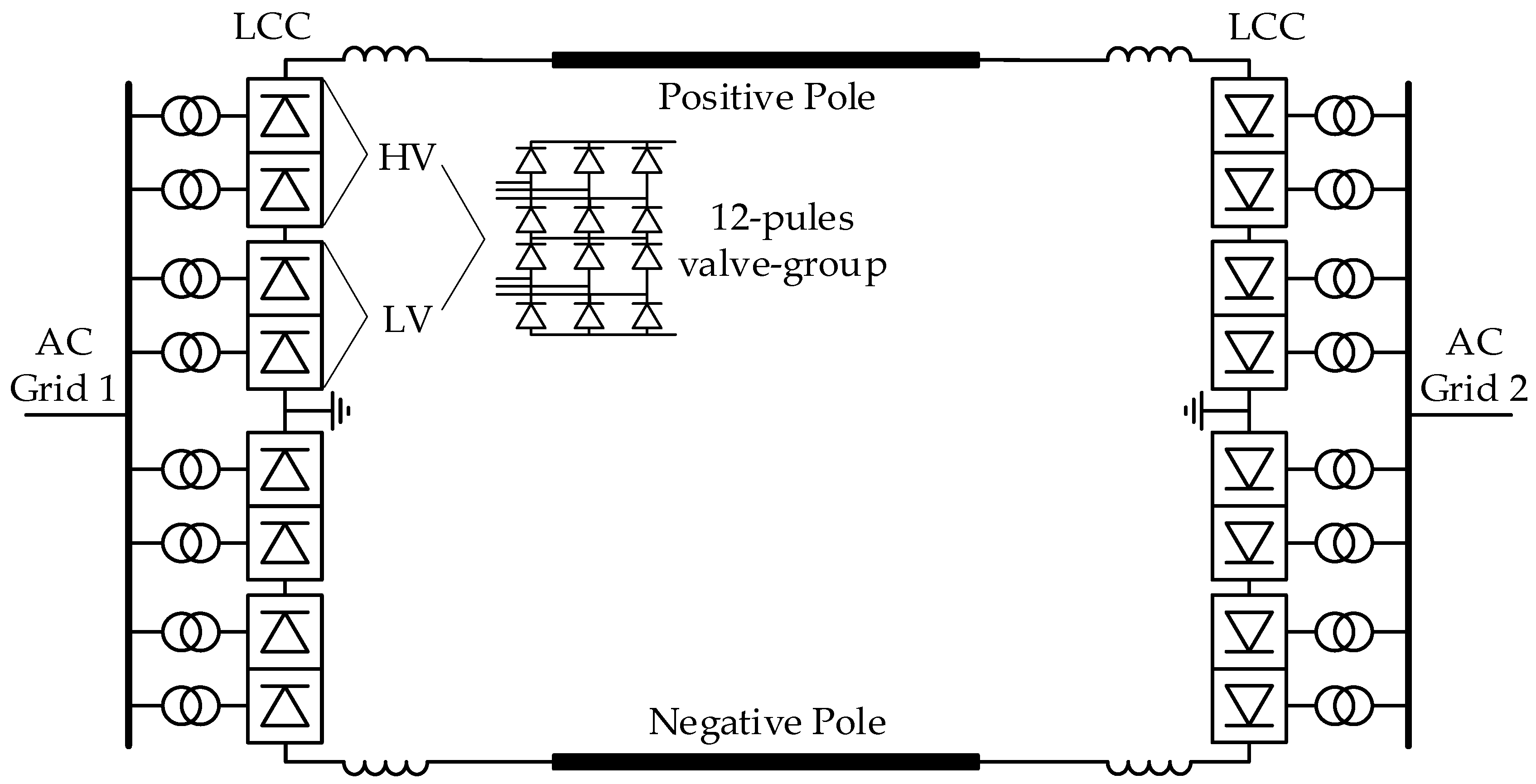
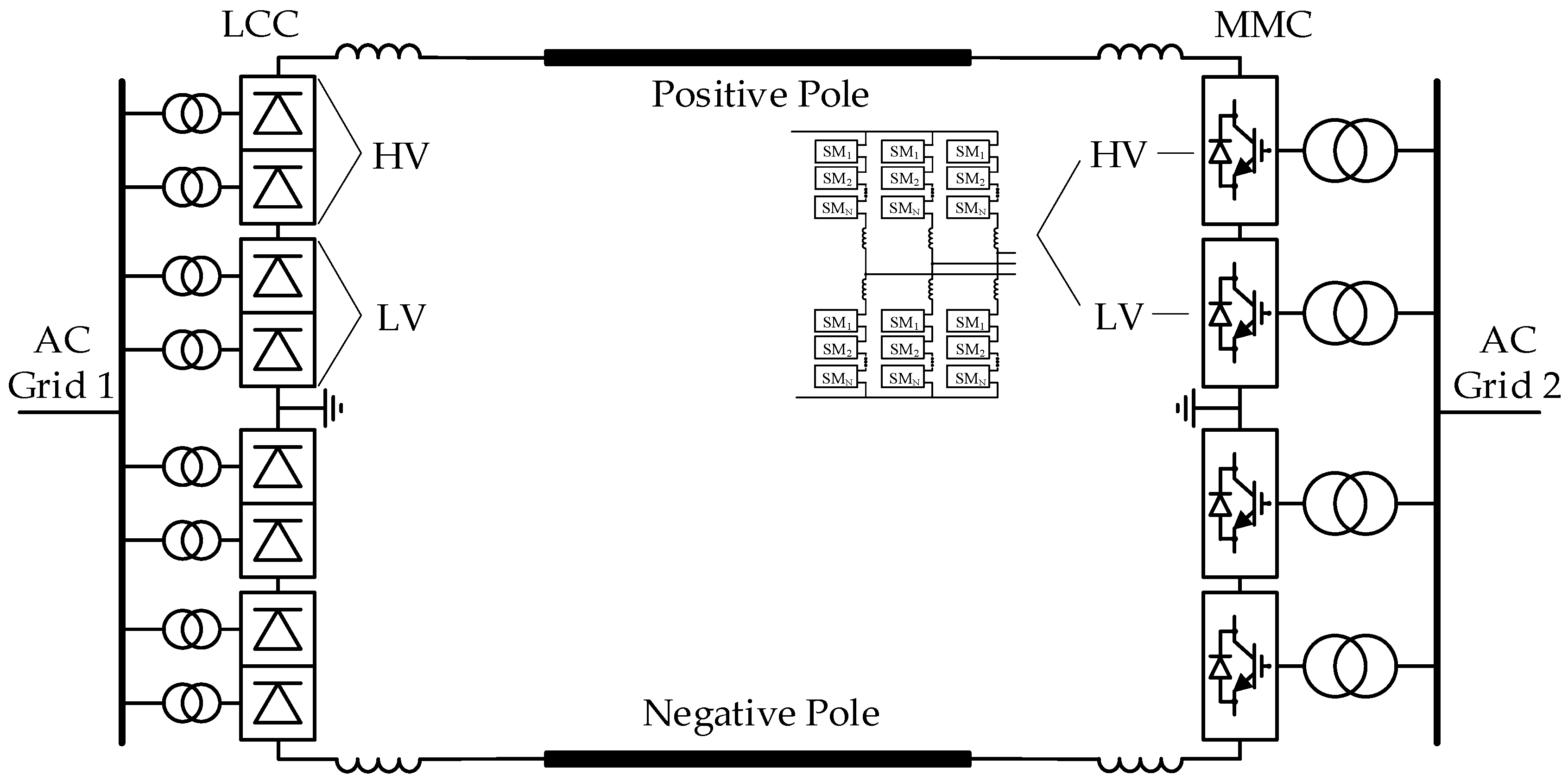
2. Converter Station Configurations of UHVDC Systems

In this section, the converter station configurations and possible operation modes of the LCC and hybrid LCC/MMC UHVDC systems are discussed. In LCC-UHVDC systems, the converters in each pole are typically built with two series-connected valve-groups, as shown in Figure 1. For the positive pole, the low-voltage (LV) valve-group is the one connecting to the ground and the high-voltage (HV) valve-group is the one connecting to the DC line. Each of the HV and LV valve-groups is a 12-pulse LCC [21], as shown in the figure. Therefore, the whole converter in each pole is a 24-pulse LCC.
Figure 2 shows a hybrid LCC/MMC UHVDC system. In this system, the LCC operates as the rectifier and the MMC operates as the inverter. This topology will not have the problem of commutation failure. The MMC station also consists of HV and LV MMC bridges, as shown in Figure 2.
There will be circumstances that partial valve-groups have to be bypassed when there are failures of components or a scheduled maintenance. Each valve-group in the above systems can operate independently. The system can achieve different operating modes with the help of the DC side bypass switch (BPS) and the isolators equipped with each valve-group, as shown in Figure 3.
The high-speed BPS is to bypass the valve-group and provide current paths during the bypassing process. The valve-group isolators ① and ② are to isolate the valve-group from the DC line when the bypass process is completed. Then the current will flow through the bypass isolator ③. With this configuration, a bipolar UHVDC transmission system has the following operating modes [21,24]:
(1)
Normal operation: both poles are in full-voltage operation; the whole system power capacity is 100%;
(2)
Partial monopole off: one-pole is in full-voltage operation while the other is partially off (25% of the rated capacity); the whole system power capacity is 75%;
(3)
Monopole off: one-pole is in full-voltage operation while the other is off; the whole system power capacity is 50%;
(4)
Partial bipole off:
  • Both poles are in (half-voltage operation) partial monopole off (each pole has 25% of the rated capacity); the whole system power capacity is 50%;
  • One-pole is off while the other is (half-voltage operation) partial monopole off (25% of the rated capacity); the whole system power capacity is 25%;
(5)
Bipole off: the whole system is shut down; the system power capacity of the whole system is 0.
Figure 4 shows several possible operating modes of the positive pole of an LCC-UHVDC system. Mode (a) is in normal (full-voltage) operation. Modes (b)–(d) are in partial monopole operation: (b) the LV valve-group is bypassed, (c) the HV valve-group is bypassed, (d) mixed HV and LV valve-groups operation. The voltage in the modes (b)–(d) is half of the rated DC voltage. The process of changing the operating mode from mode (a) to modes (b)–(d) is called full-voltage to half-voltage operation in this paper.
In order to achieve a fast and stable full-voltage to half-voltage process, control strategies should be designed properly with the consideration of the different characteristics of LCCs and MMCs. The control strategies need to avoid generating large transient overvoltage and overcurrent during the full-voltage to half-voltage process and to reduce the power loss after completing the half-voltage operation.

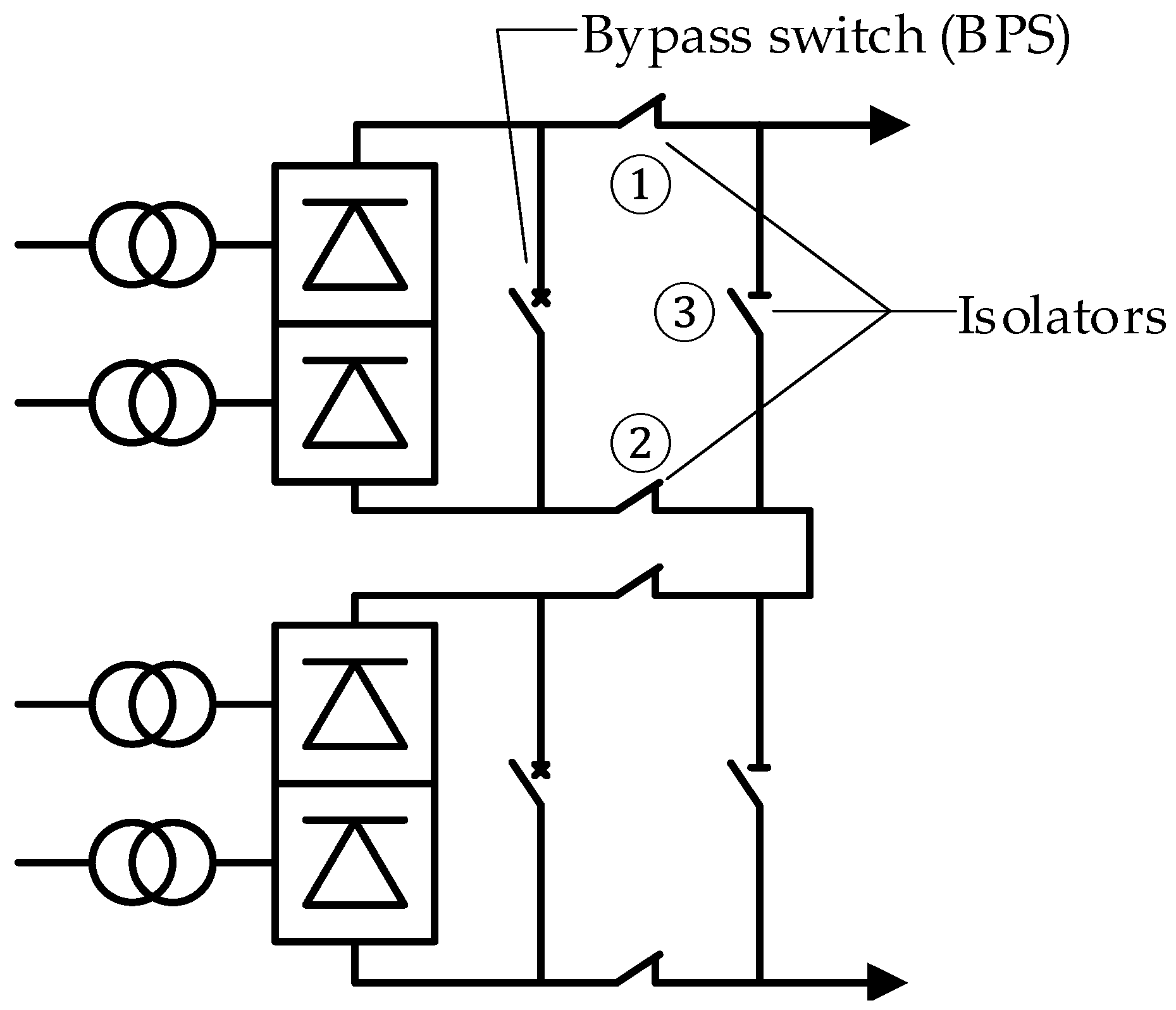
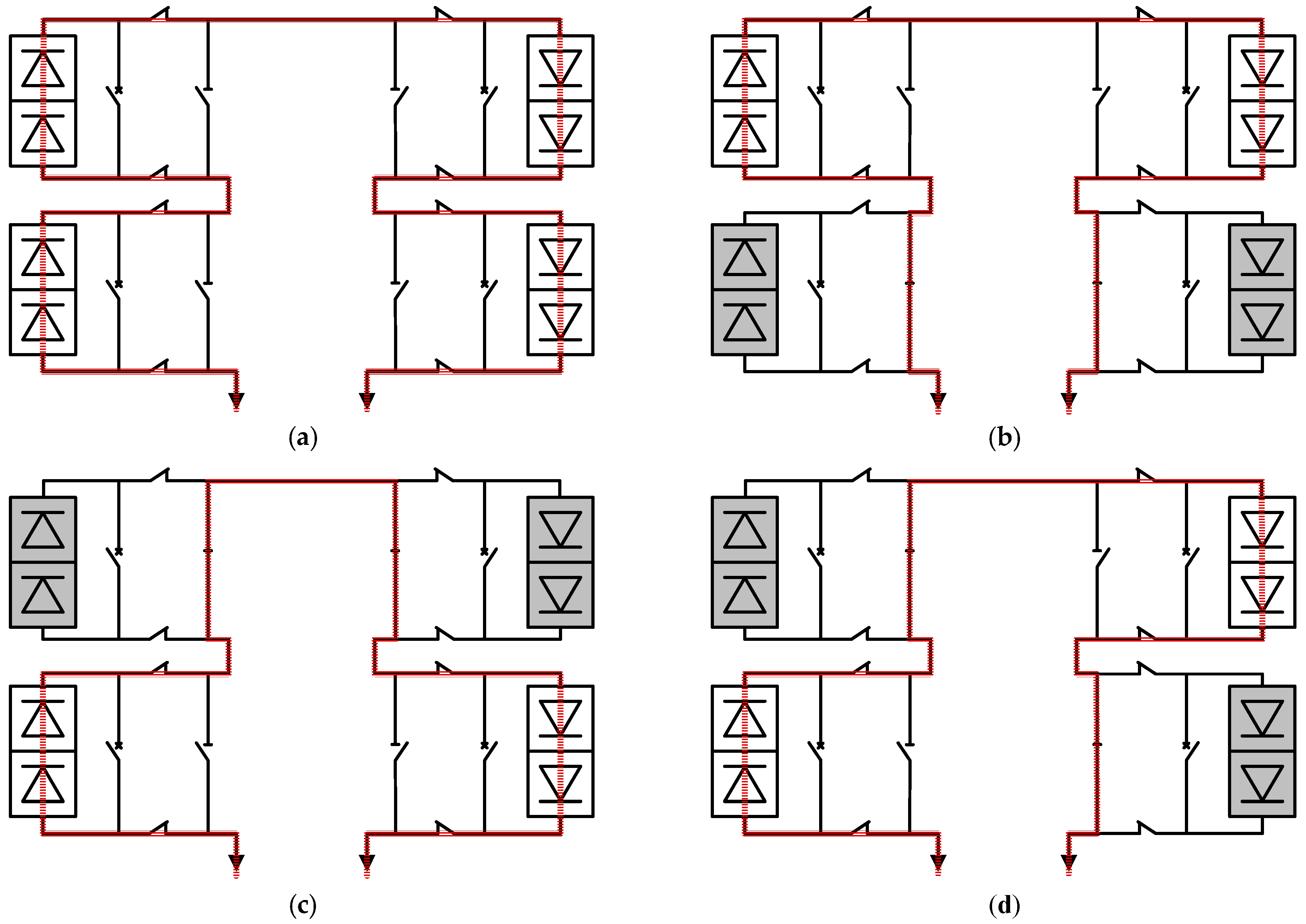
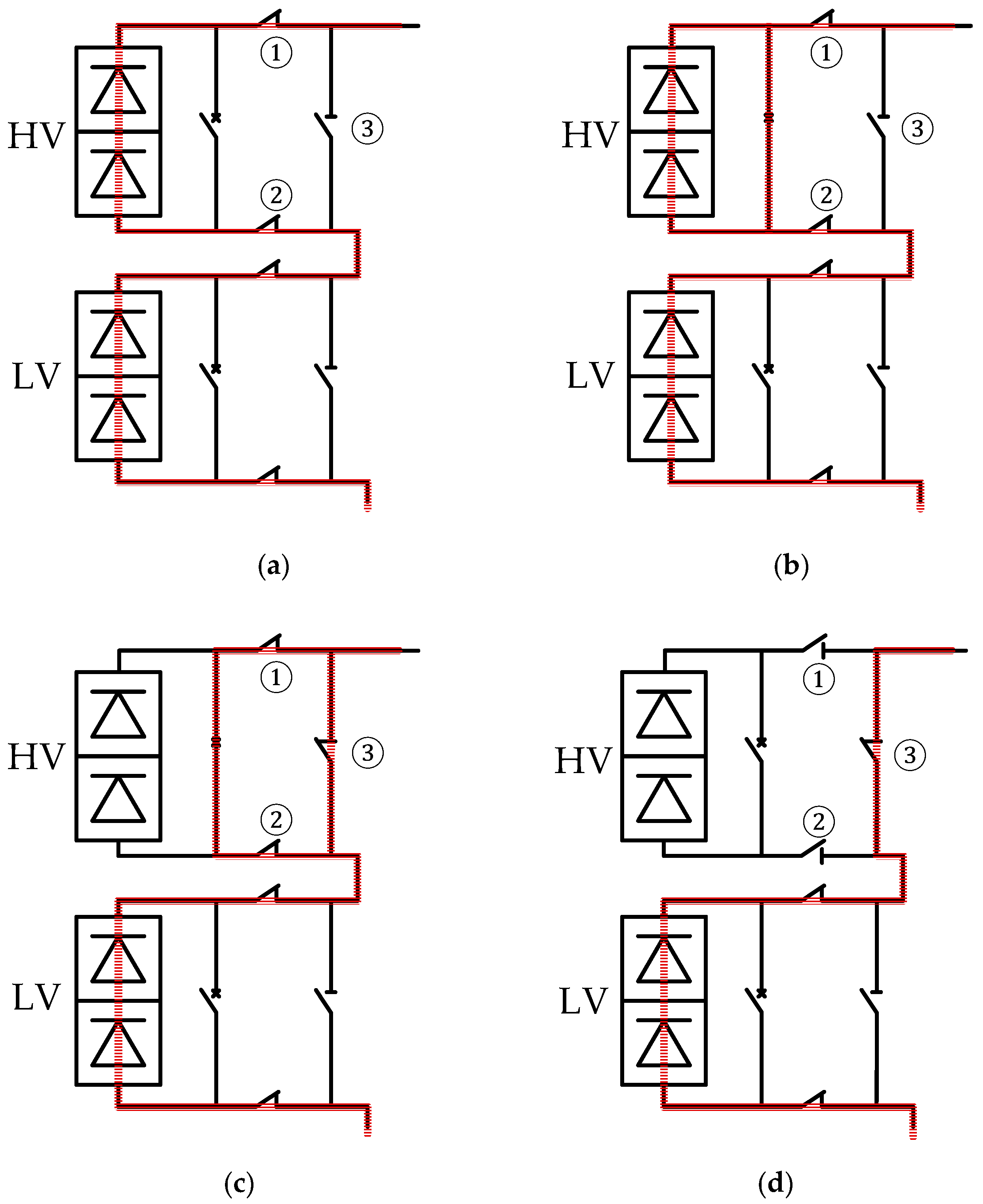
3. Valve-Group Bypassing Strategy for LCC-UHVDC

In this section, the full-voltage to half-voltage control strategy for LCC-UHVDC systems is proposed. The full-voltage to half-voltage operation can be achieved by controlling the firing angle α or extinction angle γ of the valve-groups which need to be bypassed to a large degree (e.g., 90˚). Then, the BPS and isolators will operate accordingly to achieve a smooth transition.
Figure 5 illustrates the sequence of bypassing the HV valve-group in the positive pole. In normal operating conditions, the current flows through the both HV and LV valve-groups, as shown in Figure 5a. The DC voltage of the HV valve-groups will start to decrease once the valve-groups receive the order to increase the α (or γ). The DC voltage of the LV LCC valve-group remain constant. The BPS will be closed once the DC voltage decreases to a minimum value (e.g., 0.1 p.u.) that the BPS can be closed, as shown in Figure 5b. Then, the HV valve-group will be blocked. At the same time, the bypass isolator ③ will be closed. During this process, the current will be fully transferred to the BPS and the bypass isolator ③, as shown in Figure 5c. The BPS will be opened once the isolator is fully closed. Then, the current will only flow through the isolator, as shown in Figure 5d. At last, the isolators ① and ② will be opened and the valve-group is fully isolated.
Figure 6 shows the proposed control block for the valve-groups to be bypassed. The function of the “in/out hold” is: the input is passed to the output when the hold (bypassing order) is 0; when a hold signal transition from 0 to 1 is detected, the output is held at that input sampled value. It means, in normal operation, the firing angle α or extinction angle γ is directly sent to the valves. The α or γ will be ramped up from the pre-change value with a specific ramping rate to 90˚ once the bypassing order is received from the system upper level control.
Take the system shown in Figure 1 as an example. The detailed sequences of bypassing the HV valve-groups are summarized below:
(1)
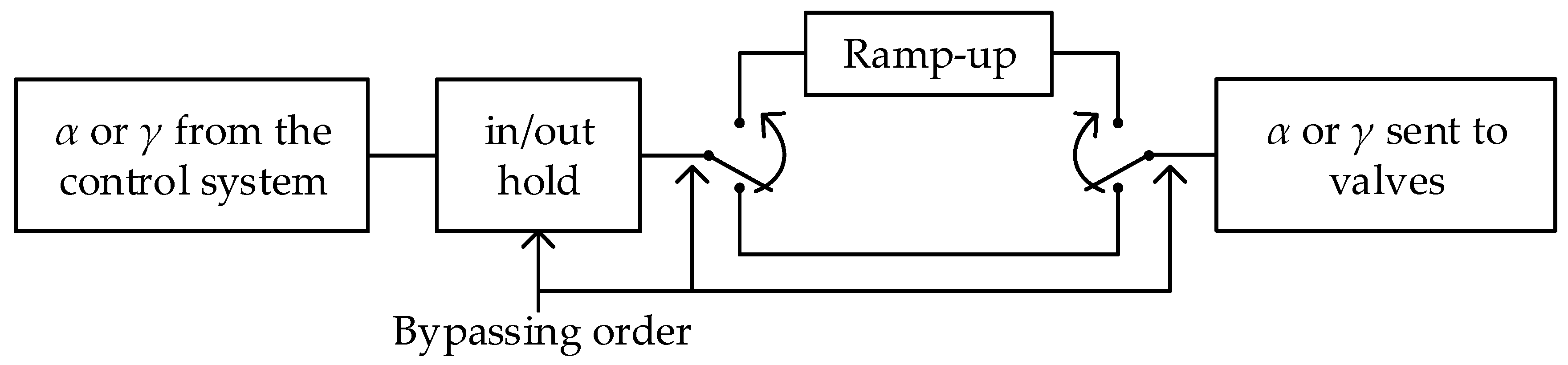
The extinction angle γ of the HV valve-group in the inverter will be ramped up to 90˚ once a bypassing order is received from the system upper level control. At the same time, the bypassing order will be transmitted to the rectifier;
(2)
The firing angle α of the HV valve-group in the rectifier will be ramped up to 90˚ once the bypassing order is received;
(3)
When the voltage of the HV valve-groups decrease to 0.1 p.u., the BPS is closed. Then, the valve-groups are blocked. At the same time, the bypass isolator will be closed;
(4)
The BPS is opened once the bypass isolator is fully closed;
(5)
The valve-group isolators are opened once the BPS is fully opened;
(6)
The full-voltage to half-voltage process completes after the above process.
It should be mentioned the above control sequences can also be applied to the LV valve-group in the positive pole and the HV or LV valve-groups in the negative pole.

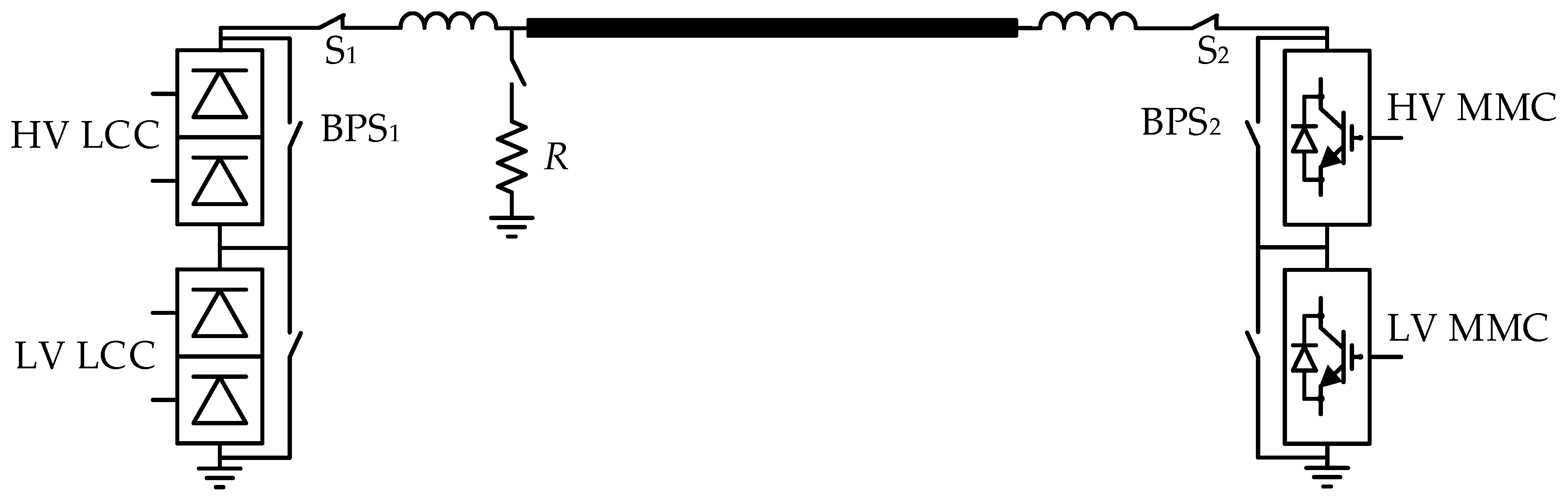
4. Valve-Group Bypassing Strategy for Hybrid LCC/VSC UHVDC

The full-voltage to half-voltage control strategies of hybrid LCC/MMC UHVDC systems will be different from the LCC-UHVDC systems due to the inherent characteristics of LCCs and MMCs. In addition, as the converter configurations of HB-MMCs and FB-MMCs are different, different control strategies should be considered for LCC/HB-MMC and LCC/FB-MMC UHVDC systems.

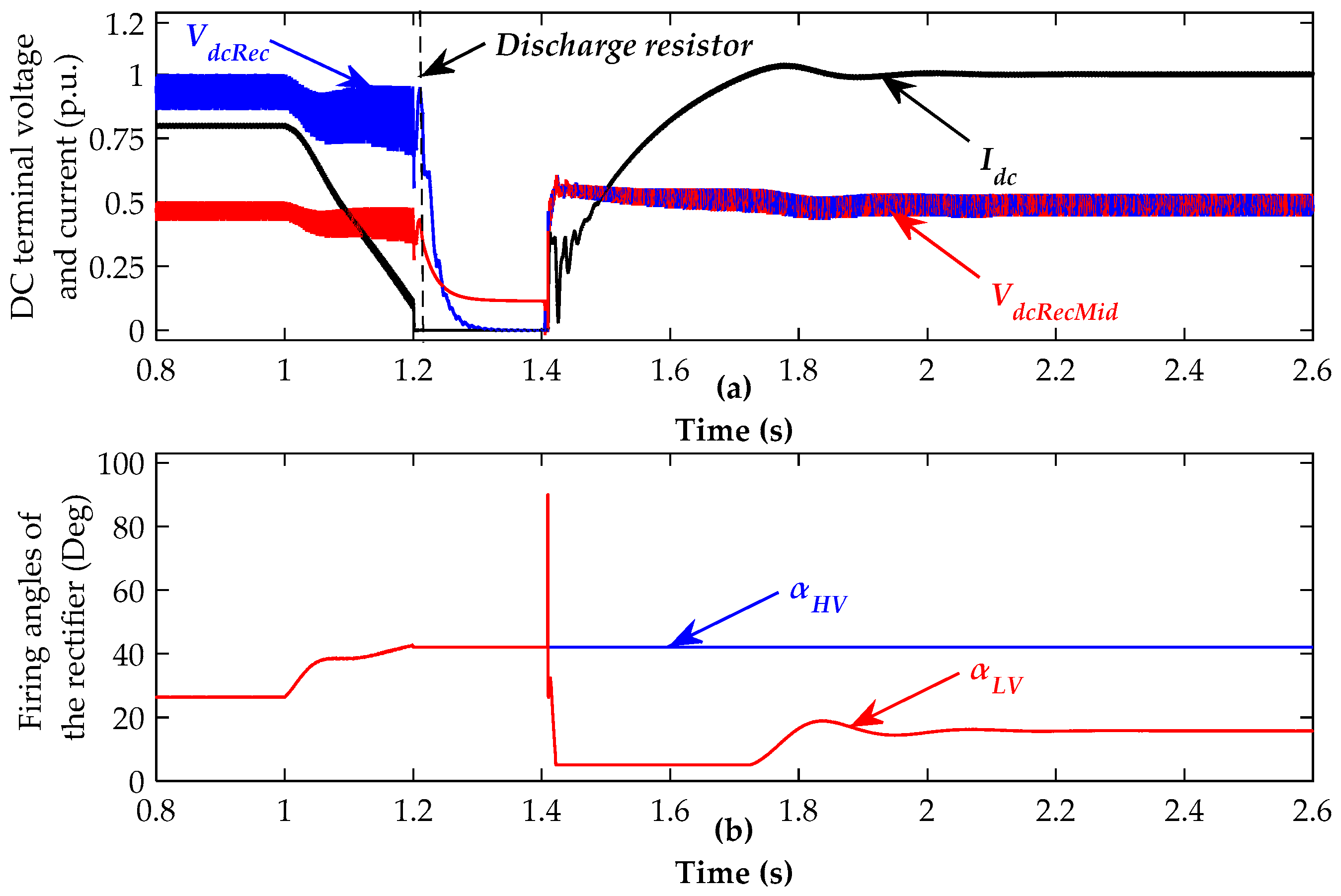
4.1. The VSC in the Hybrid System is Half-Bridge Modular Multilevel Converter (HB-MMC)

Figure 7 shows the positive pole of an LCC/HB-MMC HVDC system. The DC voltage controllability of the HB-MMC is limited within Vac to Vdc, where Vac is the converter valve-side line voltage and Vdc is the DC side pole-to-ground voltage. Therefore, it cannot adjust the DC voltage from Vdc to 0 through its DC voltage controller. In order to bypass the valve-groups, the DC current needs to be firstly reduced to a minimum value (0.1 p.u.). Then, both the HV and LV LCCs and the HV MMC need to be blocked. The LV MMC can keep operating as a static synchronous compensator (STATCOM) during the process.
Although the current in the DC line becomes zero after blocking the valve-groups, the energy stored in the DC line will make its voltage remain at a high value. The DC voltage of the DC line may take a long time to naturally decay to zero. Therefore, BPS1 and BPS2 cannot be closed directly after blocking the converters because the LV valve-groups may be damaged by the DC line residual voltage. In order to speed up the voltage decaying process, a discharging resistor is employed to achieve a fast de-energization. Before inserting the discharging resistor R, the DC side switches S1 and S2 are opened to isolate the converters from the DC line. Then, the DC line will discharge through the resistor quickly. After opening the switches S1 and S2, the BPS1 and BPS2 and isolators can operate to bypass the HV valve-groups of the LCC and MMC.
The system can restore soon after bypassing the valve-groups. The discharging resistor R will be firstly removed. Then, the DC switch S1 will be closed. The LV LCC will be deblocked to charge the DC line. The DC switch S2 will be closed when the DC line voltage reaches to the DC voltage of the LV MMC. The power transmission will be interrupted for a short time during this full-voltage to half-voltage process.
The detailed sequences of bypassing the HV valve-groups are summarized below:
(1)
Reduce the DC current to a minimum value (0.1 p.u.) once a bypassing order is received from the system upper level control;
(2)
Block the HV and LV LCCs and the HV MMC valve-groups once the DC current is reduced to the target value;
(3)
The DC terminal switches are tripped to isolate the converters from the DC line; Then, the discharging resistor is inserted; The HV valve-groups are bypassed during this process;
(4)
The discharging resistor is removed once the DC line is fully de-energized;
(5)
The LV LCC is deblocked to charge the DC line once its DC side switch is re-closed;
(6)
The LV MMC’s DC side switch is closed once the DC line voltage reaches to its DC terminal voltage;
(7)
The full-voltage to half-voltage process completes after the above process.

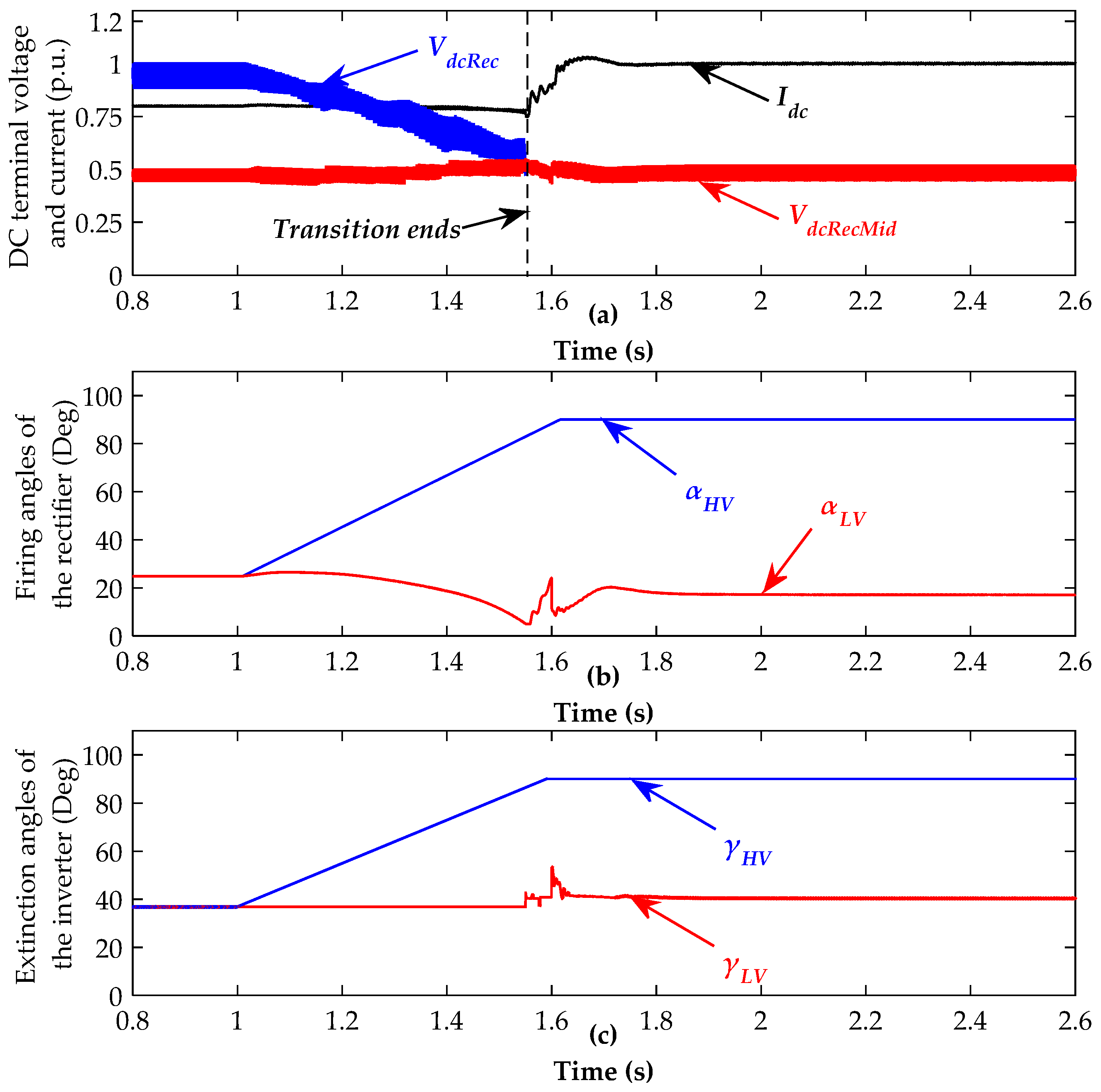
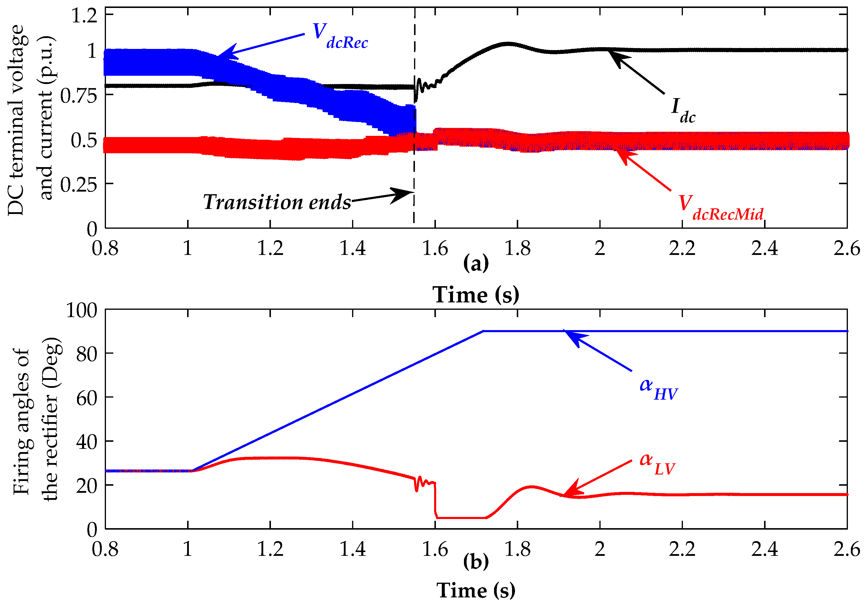
4.2. The VSC in the Hybrid System is Full-Bridge Modular Multilevel Converter (FB-MMC)

Differing from HB-MMC, FB-MMC has the capability to control the DC voltage from Vdc to −Vdc [26]. Based on the modulation and control principle of MMC, the DC voltage of a FB-MMC can be given as
V d c = i = 1 N ( S p i V c a p ) + i = 1 N ( S n i V c a p )
where Vcap is the capacitor voltage of a sub-module (SM), Spi and Sni are the switching function of the SMs in the upper arms and lower arms. The switching function has three states. For instance, the output voltage of the SM will be Vcap when Si = 1; the output voltage is 0 when Si = 0 and the output voltage is −Vcap when Si = −1. In order to achieve a stable online valve-group bypassing, the following modulation strategy is employed. The number of inserted SMs in the upper and lower arms is shown below:
{ N u p = 0.5 V d c r e f V a c r e f V c r a t e d N d o w n = 0.5 V d c r e f + V a c r e f V c r a t e d
where Nup and Ndown are the inserted SM number for the upper and lower arms, Vdcref is the DC voltage reference which will be decreased during the full-voltage to half-voltage operation with a ramp-down rate, Vacref is the MMC output ac voltage reference calculated from the control system, Vcrated is the rated SM capacitor voltage. Then the DC voltage of the MMC is
V d c = ( N u p + N d o w n ) V c a p = ( 0.5 V d c r e f V a c r e f V c r a t e d + 0.5 V d c r e f + V a c r e f V c r a t e d ) V c a p = ( V d c r e f V c r a t e d ) V c a p
From (3), the DC voltage can be controlled by regulating the DC reference, the whole SM capacitor voltage Vcap remains stable. The DC voltage outer loop controller is shown in Figure 8. To achieve an online valve-group bypass, the target valve-group of the FB-MMC will start to decrease the DC voltage. At the same time, the target valve-group of the LCC will be controlled to follow the voltage drop. The power transmission will not be interrupted during this full-voltage to half-voltage process.
The detailed sequences of bypassing the HV valve-groups are summarized below:
(1)
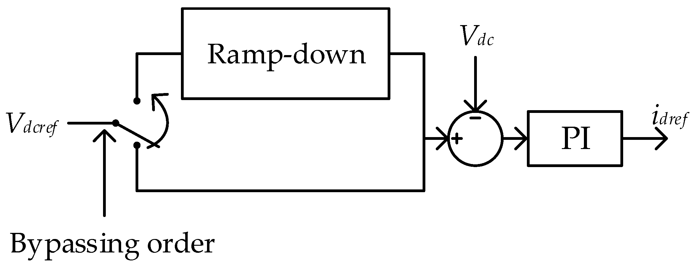
The DC voltage of the HV valve-group of the FB-MMC will be controlled to ramp down to a minimum value (0.1 p.u.) once a bypassing order is received from the system upper level control. At the same time, the bypassing order will be transmitted to the rectifier;
(2)
The firing angle α of the HV valve-group in the rectifier will be ramped up to follow the voltage decrease controlled by the FB-MMC;
(3)
When the voltage of the HV valve-groups decrease to 0.1 p.u., the BPS is closed. Then, the valve-groups are blocked. At the same time, the bypass isolator will be closed;
(4)
The BPS is opened once the bypass isolator is fully closed;
(5)
The valve-group isolators are opened once the BPS is fully opened;
(6)
The full-voltage to half-voltage process completes after the above process.

5. Power Rescheduling Strategy for Full-Voltage to Half-Voltage Operation

After completing the process of full-voltage to half-voltage operation, the system may lose some power transmission capability. In order to minimize the load-shedding caused by the half-voltage operation, a power rescheduling strategy has to be designed.
Assuming the power transmitted in each valve-group is equal and the value is P0 before the full-voltage to half-voltage process, therefore, the power transmitted in each pole is 2P0 and the total power of the system is 4P0. The rated power of each valve-group is Prated. Therefore, P0 ≤ Prated. The detailed sequences of the power rescheduling are summarized below:
(1)
If P0 ≤ ½Prated, the new power reference for the half-voltage operating valve-group will be set as 2P0. The power reference for the full-voltage operating pole is not changed. In this case, there is no power loss.
(2)
If ½Prated < P0 ≤ ¾Prated, the new power reference for the half-voltage operating valve-group will be set as Prated. In this case, the increased power of the half-voltage valve-group is (Prated ‒P0), the lost power is P0 ‒ (Prated ‒ P0) = (2P0 ‒ Prated) which can be undertaken by the full-voltage operating pole. It is known the original power in the full-voltage operating pole is 2P0. As P0 ≤ ¾Prated, therefore (2P0 ‒ Prated) + 2P0 = (4P0 ‒ Prated) ≤ 2Prated. Therefore, the new power reference for the full-voltage operating pole is set to (4P0 ‒ Prated). In this case, power loss of the system is 0.
(3)
If ¾Prated < P0 ≤ Prated, the new power reference for the half-voltage operating valve-group will be set as Prated. The power reference for the full-voltage operating valve-group will be set as 2Prated. In this case, the power loss in the system is (4P0 ‒ 3Prated).
The power rescheduling strategy is summarized in Table 1.

6. Case Studies

The above analysis and proposed control strategies are verified in the LCC and hybrid LCC/MMC UHVDC systems built in PSCAD/EMTDC. It should be mentioned that a simulation time step of 10 μs is used to ensure the accuracy of the simulation.

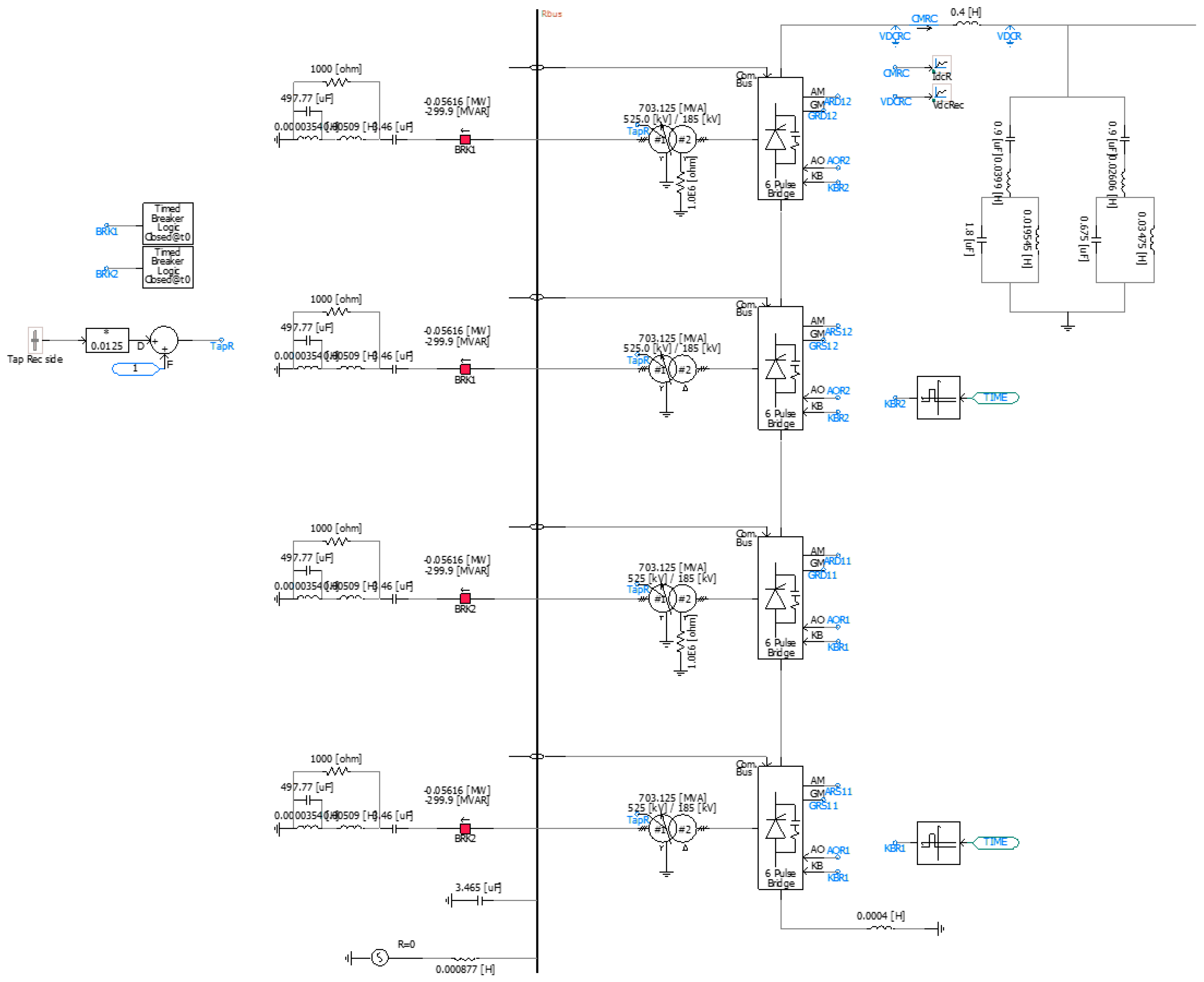
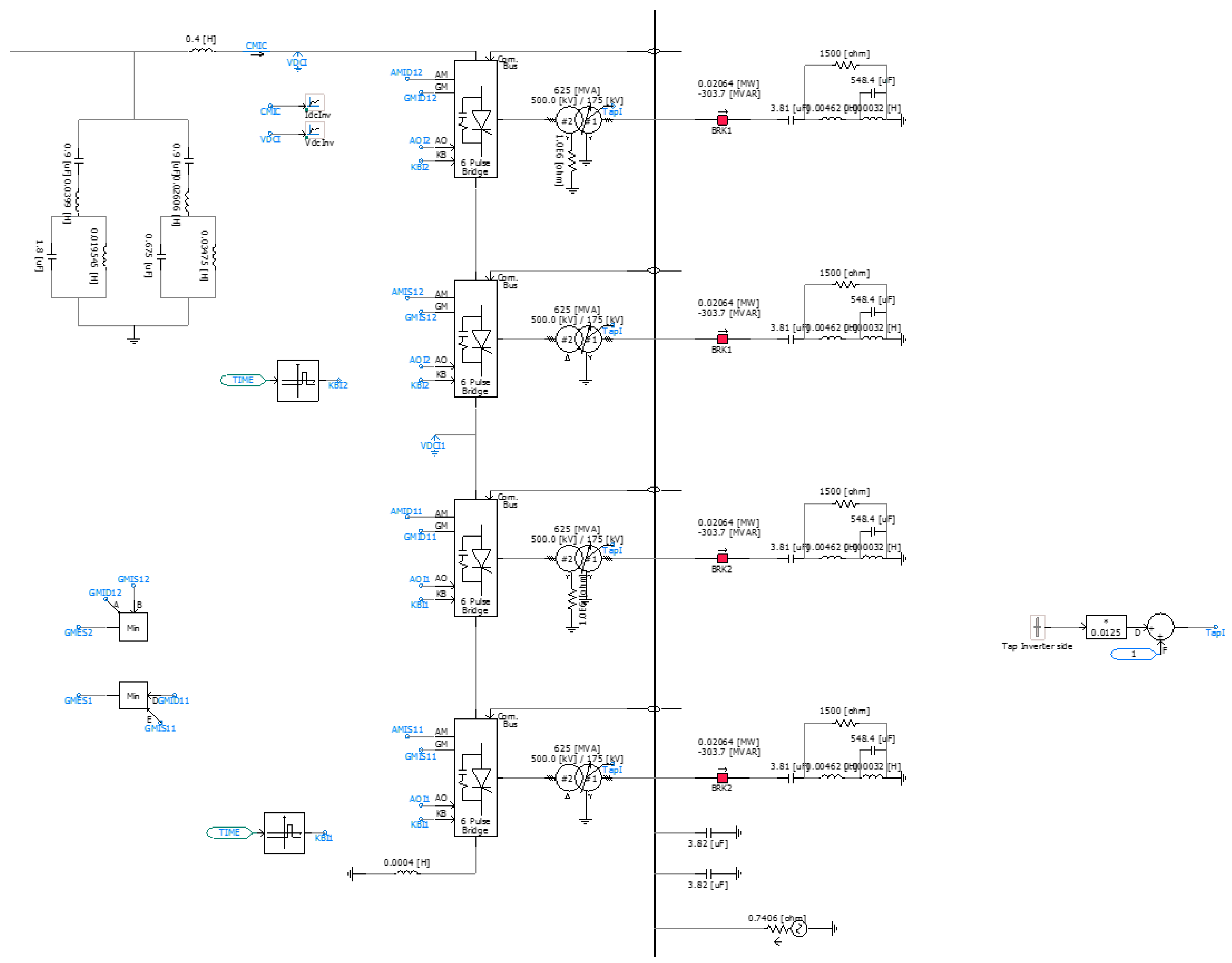
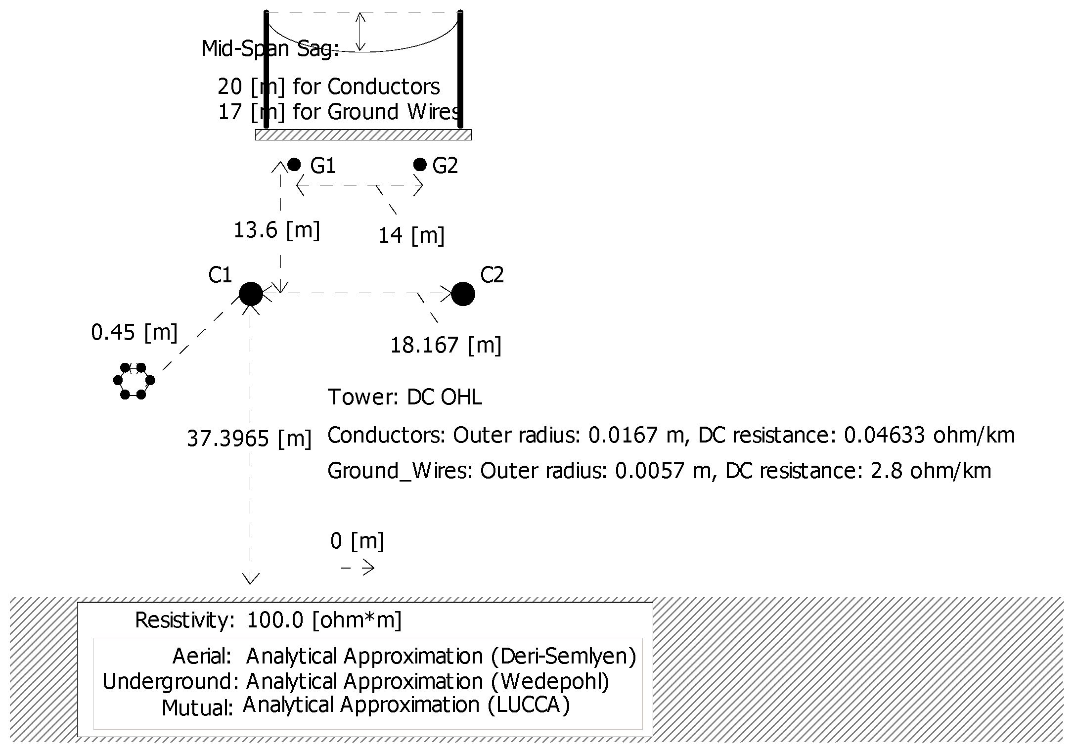
6.1. LCC-UHVDC Point-to-Point Link

A ±800 kV, 5GW LCC-UHVDC system has been built in PSCAD/EMTDC. The system configuration is shown in Figure 1. The parameters are modified based on the Xiangjiaba–Shanghai LCC-UHVDC project. The parameters of the converters, transformers, ac and DC side filters are given in Table 2 and shown in Figure A1 and Figure A2 in the Appendix A. The Frequency Dependent DC overhead line model (dimensions and parameters) in PSCAD is illustrated in Figure A3 in the Appendix A as well. The DC link distance is set as 1450 km. The HV valve-groups in the positive pole are bypassed as an example to achieve the full-voltage to half-voltage operation.
Figure 9 illustrates the system dynamics during the full-voltage to half-voltage operation. The initial DC current (power) was set as 0.8 p.u. The inverter received bypassing signal at t = 1 s. A 10 ms delay is set for the rectifier to receive the bypassing signal to represent the communication delay. VdcRec is the DC terminal voltage of the rectifier. As shown in Figure 9a, VdcRec started to drop once the firing angle is controlled to increase to 90˚. The VdcRecMid is the voltage between the HV and LV valve-groups of the rectifier. It can be seen that the VdcRecMid and the DC current Idc were almost not affected during the full-voltage to half-voltage control process. It is because the voltage reduction of the HV valve-group does not affect the voltage of the LV valve-group which can keep controlling the DC current constantly. According to the proposed power reschedule strategy, the current (power) was then set to 1 p.u. when the BPS and isolators successfully operated to isolate HV valve-groups. The power transmission is not interrupted during the full-bridge to half-bridge process. Figure 9b,c show the firing angles and extinction angles of the rectifier and inverter, respectively. The firing angles and extinction angles of the HV valve-groups were controlled to ramp up once the bypassing signals were received. It should be mentioned that the HV valve-groups may have been blocked before their firing or extinction angle reaches to 90˚.
Figure 10a shows the voltage and current of the negative pole. The firing angle of the rectifier of the negative pole is shown in Figure 10b. According to the proposed power reschedule strategy, the current (power) was increased to 1 p.u. at t = 1.6 s to compensate the power loss caused by the half-voltage operation of the positive pole. The power loss of the whole system is 6.25% of its initial power.

6.2. Hybrid LCC/HB-MMC UHVDC Point-to-Point Link

A ±800 kV, 5GW LCC/HB-MMC UHVDC system has been built in PSCAD. The inverter in the previous case is replaced by a HB-MMC with HV and LV valves. The LCC parameters and DC line are the same with the previous case. The parameters of the MMC are shown in Table 3.
Figure 11 illustrates the dynamic performance of the system. The initial DC current (power) was set as 0.8 p.u.. The DC current started to reduce to 0.1 p.u. at t = 1 s. Then, the HV and LV LCCs and the HV MMC were blocked at t = 1.2 s. The DC switches at the two terminals of the DC line were tripped after blocking the converters. Then, the discharging resistor was inserted until the DC circuit voltage decayed to zero. During this period, the HV valve-groups of the LCC and MMC were isolated by their bypass switches and isolators. The LV LCC’s DC side switch was re-closed at t = 1.4 s. The controller of LV LCC was reset (the initial firing angle was 90˚) and deblocked at t = 1.41 s. The LV MMC’s DC side switch was closed at t = 1.45 s. Then, the current was controlled to increase to 1 p.u.

6.3. Hybrid LCC/FB-MMC UHVDC Point-to-Point Link

A ±800 kV, 5GW LCC/FB-MMC UHVDC system has been built in PSCAD. The inverter in the previous case is replaced by an FB-MMC with HV and LV valves. The parameters of the FB-MMC is the same with the HB-MMC in the previous case.
Figure 12 illustrates the dynamic performance of the system. The initial DC current (power) was set as 0.8 p.u.. The DC voltage controller of the HV FB-MMC started to reduce the DC voltage at t = 1 s. At the same time, the firing angle ( α H V in the figure) of the HV LCC started to increase. During this period, the controller of the LV LCC was operating to control the DC current to be constant. The HV LCC and MMCs were blocked when the DC output voltage of the HV LCC reduced to 0.1 p.u. (0.6 p.u. of the DC line voltage). Then the bypass switches and isolators operated to isolate the HV LCC valve-groups. Then, the current was controlled to increase to 1 p.u. The power transmission is not interrupted during the full-bridge to half-bridge process.

7. Conclusions

This paper investigated the control strategies of full-voltage to half-voltage operation for LCC and hybrid LCC/MMC UHVDC systems. The full-voltage to half-voltage process can be achieved within several hundred milliseconds by the proposed strategies without inducing large transient overvoltage and overcurrent. A fast full-voltage to half-voltage operation for a hybrid LCC/HB-MMC UHVDC system needs the help of a DC side discharging resistor. Therefore, it will experience a short time power outage during the full-voltage to half-voltage process. While the LCC and LCC/FB-MMC UHVDC systems can be achieved online valve-group bypassing without interrupting the power transmission. Moreover, a power reschedule strategy has been proposed to achieve a minimum power loss caused by the half-voltage operation. The proposed strategies have been verified through time-domain simulations conducted in PSCAD/EMTDC. The studies can be a useful guidance for the operation and control for future UHVDC systems

Author Contributions

The authors contribute to this paper equally.

Funding

The authors acknowledge the funding from Science and Technology Project of the State Grid Corporation of China, “HVDC Systems/Grids for Transnational Interconnections”, project number: SGTYHT/16-JS-198.

Conflicts of Interest

The authors declare no conflict of interest.

Appendix A

Figure A1. The sending end LCC PSCAD model.
Energies 12 00742 g0a1
Figure A2. The receiving end LCC PSCAD model.
Energies 12 00742 g0a2
Figure A3. The dimensions and parameters of the ± 800 kV overhead line model in PSCAD.
Energies 12 00742 g0a3

References

  1. Wang, Y.; Wen, W.; Wang, C.; Liu, H.; Zhan, X.; Xiao, X. Adaptive Voltage Droop Control of Multiterminal VSC-HVDC Systems for DC Voltage Deviation and Power Sharing. IEEE Trans. Power Del. 2019, 34, 169–176. [Google Scholar] [CrossRef]
  2. Li, G.; Liang, J.; Ugalde-Loo, C.E.; Coventry, P.; Rimez, J. Dynamic interactions of DC and AC grids subject to DC faults. In Proceedings of the 2016 IEEE 8th International Power Electronics and Motion Control Conference (IPEMC-ECCE Asia), Hefei, China, 22–26 May 2016; pp. 2627–2633. [Google Scholar]
  3. Bucher, M.K.; Franck, C.M. Contribution of Fault Current Sources in Multiterminal HVDC Cable Networks. IEEE Trans. Power Del. 2013, 28, 1796–1803. [Google Scholar] [CrossRef] [Green Version]
  4. Li, G.; Li, C.; van Hertem, D. HVDC technology overview. In HVDC Grid: For Offshore and Supergrid of the Future; Wiley-IEEE: Piscataway, NJ, USA, 2016; Chapter 3; pp. 45–78. [Google Scholar]
  5. Joseph, T.; Ugalde-Loo, C.E.; Liang, J.; Coventry, P.F. Asset Management Strategies for Power Electronic Converters in Transmission Networks: Application to Hvdc and FACTS Devices. IEEE Access 2018, 6, 21084–21102. [Google Scholar] [CrossRef] [Green Version]
  6. Barnes, M.; van Hertem, D.; Teeuwsen, S.P.; Callavik, M. HVDC Systems in Smart Grids. Proc. IEEE 2017, 105, 2082–2098. [Google Scholar] [CrossRef]
  7. World’s Biggest Ultra-High Voltage Line Powers Up Across China. Available online: https://www.bloomberg.com/news/articles/2019-01-02/world-s-biggest-ultra-high-voltage-line-powers-up-across-china (accessed on 15 January 2019).
  8. Perez, M.A.; Bernet, S.; Rodriguez, J.; Kouro, S.; Lizana, R. Circuit Topologies, Modeling, Control Schemes, and Applications of Modular Multilevel Converters. IEEE Trans. Power Electron. 2015, 30, 4–17. [Google Scholar] [CrossRef]
  9. Li, G.; Liang, J.; Ma, F.; Ugalde-Loo, C.E.; Liang, H. Analysis of Single-Phase-to-Ground Faults at the Valve-Side of HB-MMCs in HVDC Systems. IEEE Trans. Ind. Electron. 2019, 66, 2444–2453. [Google Scholar] [CrossRef]
  10. Kouro, S.; Malinowski, M.; Gopakumar, K.; Pou, J.; Franquelo, L.G.; Wu, B.; Rodriguez, J.; Perez, M.A.; Leon, J.I. Recent Advances and Industrial Applications of Multilevel Converters. IEEE Trans. Ind. Electron. 2010, 57, 2553–2580. [Google Scholar] [CrossRef]
  11. TBEA. The World’s First-ever ±800kV Modular Multilevel Converter Valve has been Developed. Available online: http://en.tbeaenergy.com/content/details144_1804.html (accessed on 15 January 2018).
  12. RXPE. RXHK Awarded World’s Largest VSC HVDC Converter Contract. Available online: http://www.rxpe.co.uk/corporate/news/worlds-largest-vsc-hvdc-converter-order/ (accessed on 15 January 2018).
  13. Song, J. Analysis of Hybrid LCC-VSC HVDC Transmission Systems. Master’s Thesis, Universitat Politècnica de Catalunya UPC, Barcelona, Spain, 2018. [Google Scholar]
  14. Lebre, J.R.; Portugal, P.M.M.; Watanabe, E.H. Hybrid HVDC (H2VDC) System Using Current and Voltage Source Converters. Energies 2018, 11, 1323. [Google Scholar] [CrossRef]
  15. Li, G.; Liang, J.; Joseph, T.; An, T.; Szechtman, M.; Andersen, B.; Zhuang, Q. Start-up and Shut-down Strategies of Hybrid LCC/VSC DC Grids. In Proceedings of the 2018 2nd IEEE Conference on Energy Internet and Energy System Integration (EI2), Beijing, China, 20–22 October 2018; pp. 1–5. [Google Scholar]
  16. Mohamed Haleem, N.; Rajapakse, A.D.; Gole, A.M.; Fernando, I.T. Investigation of Fault Ride-Through Capability of Hybrid VSC-LCC Multi-Terminal HVDC Transmission Systems. IEEE Trans. Power Del. 2019, 34, 241–250. [Google Scholar] [CrossRef]
  17. Li, G.; Liang, J.; Joseph, T.; An, T. Feasibility and Reliability Analysis of LCC DC Grids and LCC/VSC Hybrid DC Grids. IEEE Access 2019. [CrossRef]
  18. Ying, H.; Weihuang, H.; Ming, L.; Tao, L. Steady-state control strategy of multi-terminal hybrid UHVDC. In Proceedings of the 2017 19th European Conference on Power Electronics and Applications (EPE’17 ECCE Europe), Warsaw, Poland, 11–14 September 2017; pp. 1–10. [Google Scholar]
  19. Liu, Z.; Yu, J.; Guo, X.; Sun, T.; Zhang, J. Survey of technologies of line commutated converter based high voltage direct current transmission in China. CSEE J. Power Energy Syst. 2015, 1, 1–8. [Google Scholar] [CrossRef]
  20. Rao, H.; Xu, S.; Zhou, Y.; Zhu, Z. Research on Main Circuit Scheme of VSC-UHVDC. Southern Power Syst. Technol. 2017, 11, 1–4. [Google Scholar]
  21. Xie, K.; Hu, B.; Singh, C. Reliability Evaluation of Double 12-Pulse Ultra HVDC Transmission Systems. IEEE Trans. Power Del. 2016, 31, 210–218. [Google Scholar]
  22. Vithayathil, J.J. Bypass operation in bridge convertors for high-voltage d.c. transmission. Proc. IEEE 1965, 112, 359–365. [Google Scholar]
  23. Machida, T.; Yoshida, Y.; Fujii, N.; Yokoyama, K. Bypass control system for high-voltage dc converter using semiconductor control rectifiers. U.S. Patent 3,636,431, 18 January 1972. [Google Scholar]
  24. Li, Y.; Huang, L.; Hong, C.; Li, X. Analysis on the Strategy of Block/Deblock Dual 12-Pulse Valve Groups in ±800 kV DC Transmission System. Southern Power Syst. Technol. 2010, 4, 21–25. [Google Scholar]
  25. Li, D.; Wang, Y.; Ding, L.; Li, X.; Dai, H.; Su, G. Blocking and deblocking strategy of single UHVDC converter group under joint control mode of dual 12-pulse converter groups. Electr. Power Autom. Equip. 2014, 34, 148–154. [Google Scholar]
  26. Yu, L.; Guo, C.; Zhao, C.; Xu, J.; An, N.; Hu, X. Power Reversal of Hybrid HVDC System. In Proceedings of the 11th IET International Conference on AC and DC Power Transmission, Birmingham, UK, 10–12 February 2015; pp. 1–6. [Google Scholar]
Figure 1. A typical line commuted converter (LCC) ultra high-voltage direct-current (UHVDC) system.
Energies 12 00742 g001
Figure 2. A hybrid LCC/modular multilevel converter (MMC) UHVDC system.
Energies 12 00742 g002
Figure 3. The bypass switches and isolators equipped with the valve-groups.
Energies 12 00742 g003
Figure 4. Possible operation modes of the positive pole of an LCC-UHVDC system. (a) Normal operation; (b) High-voltage (HV) valve-groups operation; (c) Low-voltage (LV) valve-groups operation; (d) Mixed valve-groups operation.
Energies 12 00742 g004
Figure 5. The sequence of bypassing the HV valve-group. (a) Normal operation; (b) BPS closed; (c) Valve blocked, isolator closed; (d) Half-voltage operation.
Energies 12 00742 g005
Figure 6. The valve-group bypassing control logic.
Energies 12 00742 g006
Figure 7. The positive pole of an LCC/half-bridge (HB)-MMC UHVDC system.
Energies 12 00742 g007
Figure 8. DC voltage outer loop controller of the full-bridge (FB)-MMC.
Energies 12 00742 g008
Figure 9. System dynamics during the full-voltage to half-voltage operation of the LCC-UHVDC link. (a) DC terminal voltage and current of the sending end; (b) Firing angles of the LV and HV valve-groups of the sending end; (c) Extinction angles of the LV and HV valve-groups of the receiving end.
Energies 12 00742 g009
Figure 10. System dynamics of the negative pole. (a) DC terminal voltage and current of the sending end; (b) Firing angle of the sending end.
Energies 12 00742 g010
Figure 11. System dynamics during the full-voltage to half-voltage operation of the Hybrid LCC/HB-MMC UHVDC link. (a) DC terminal voltage and current of the sending end; (b) Firing angles of the LV and HV valve-groups of the sending end.
Energies 12 00742 g011
Figure 12. System dynamics during the full-voltage to half-voltage operation of the Hybrid LCC/FB-MMC UHVDC link. (a) DC terminal voltage and current of the sending end; (b) Firing angles of the LV and HV valve-groups of the sending end.
Energies 12 00742 g012
Table 1. Power rescheduling strategy.
Initial Power of Each Valve-GroupPower Reference for Half-Voltage PolePower Reference for
Full-Voltage Pole
System
Power Loss
P0 ≤ ½Prated2P02P00
½Prated < P0 ≤ ¾PratedPrated4P0 ‒ Prated0
¾Prated < P0 ≤ PratedPrated2Prated4P0 ‒ 3Prated
Table 2. System parameters.
ParametersReal Value
Capacity (MVA)5000
Rated DC voltage (kV)±800
AC grid frequency (Hz)50
Rated AC voltages (kV) 525 (Rec)
500 (Inv)
Transformer ratios (kV/kV)525/185 (Rec)
500/175 (Inv)
Transformer capacity per valve (MVA)703.125 (Rec)
625 (Inv)
Transformer leakage inductance (p.u.)0.14
Table 3. Parameters of the HB-MMC.
ParametersReal Value
Capacity (MVA)5000
Rated DC voltage (kV)± 800
AC grid frequency (Hz)50
Rated AC voltages (kV) 500
Transformer ratios (kV/kV)500/260
Transformer capacity per valve (MVA)1250
Transformer leakage inductance (p.u.)0.14
Number of SM 167
SM capacitor (mF)18

