Abstract
High-voltage electro pulse boring (EPB) has the advantages of high rock-breaking efficiency and good wall quality, and is a new and efficient potential method of rock breaking. The EPB process is defined as random because it is affected by many factors. At present, there is no suitable physical and mathematical model to describe the process and results of rock breakage in EPB, and the conclusions reached regarding rock-breakage mechanisms are not uniform. In this study, a complete damage model of high voltage EPB in granite is established, which includes a shock wave model and a damage model of high voltage EPB in granite. The damage model is based on the Particle Flow Code two-dimensional program. Use of a damage model of EPB accommodates the complete process of high voltage EPB, from discharge to production of a shock wave, and so rock-breaking via electro pulse can be simulated and calculated. The time-varying waveforms of shock waves with different electrical parameters are simulated and calculated on the basis of the model. Different shock wave forms are loaded into the surface and internal rock in the damage geometric model of EPB granite. Then, the breakage process of the rock surface and internally, and the mechanism of rock breakage using EPB are analyzed. This study provides a scientific basis for the quantitative expression and prediction of rock fragmentation in EPB in order to improve the drilling efficiency and reduction of energy loss in the process of EPB.
1. Introduction
The drilling depth of oil, natural gas, and geothermal wells is increasing [1]. Traditional mechanical drilling has the disadvantages of low drilling efficiency, high drilling cost, and large bit wear in the processes of deep drilling, ultra-deep drilling, and hard rock drilling. At the same time, the construction methods of rapid excavation and tunneling in medium-hard rock and hard rock, such as drilling and blasting method and full-face hard rock tunneling, have shortcomings, such as high consumption costs and stricter requirements on geological conditions [2]. It is, therefore, an imperative to study high-efficiency rock-breaking drilling technology. High voltage electro pulse rock breaking technology has the characteristics of controllable energy, no pollution, and no flying stones [3]. Rock breaking using high voltage electro pulse discharge can be divided into hydroelectric and electric pulse rock breaking. Compared with hydroelectric rock breaking, electro pulse rock breaking has the advantages of high rock breaking efficiency and low energy consumption. Electro pulse rock breaking technology has been widely used in rock mining, micro-ore decomposition, rock drilling, scale cleaning, and mineral recovery [4]. The studies of rock mechanics models and the breaking mechanisms of EPB are very important for predicting rock breaking, improving drilling efficiency and reducing energy loss. A complete damage model of high-voltage EPB in granite is established in this study. The complete process of high voltage EPB, from discharge to production of a shock wave, can be simulated and calculated through the damage model that considers the defects of the rock itself. By means of numerical experiments, the influence law of electrical parameters on the breaking efficiency is obtained, and then the critical conditions of increasing breaking efficiency are proposed. The rock breaking mechanism of EPB is obtained, which is consistent with the experimental results. The rationality and feasibility of the damage model of EPB in granite are proved.
This paper takes hard granite as the research object. A review of previous studies on mechanical model and breakage mechanism of EPB is introduced in Section 2. The process of rock breaking using EPB is introduced in Section 3. A damage model of high-voltage EPB in granite is built in Section 4. In Section 4.1, the shockwave model for EPB in granite is established according to the equivalent circuit model, the cylindrical plasma channel model, and the principle of energy balance. In Section 4.2, the damage model, based on the Particle Flow Code two-dimensional program (PFC2D; PFCTM 5.0, Itasca Consulting Group Inc., Twin Cities, MN, USA) of EPB in granite, is established. The results and discussion are presented in Section 5. According to the shock wave waveform obtained, the numerical experiment of EPB is carried out in Section 5.1, based on the particle discrete element method using particle flow software Particle Flow Code two-dimensional program (PFC2D). The fracture process and mechanism of high voltage EPB in surface and in the internal mesoscopic medium of granite are revealed under the multi-physics fields of electric field, temperature field, displacement field, and flow field in Section 5.2 and Section 5.3. Finally, conclusions are drawn in Section 6.
2. Review of Previous Studies on Mechanical Model and Breakage Mechanism of EPB
Since the 1960s, scholars found that the breakdown voltage of water was higher than that of rock when the high voltage of the short rising edge was loaded. Rock could be immersed into water and broken by a high voltage electro pulse. The fact was summarized after thirty years [5]. At present, scholars mainly study the transmission cable of EPB, pulse power supply, rock breaking process, and application of EPB. Divergences exist in basic research such as the mechanical model of rock breakage and breakage mechanism of EPB [6]. A review of previous studies on the mechanical model and breakage mechanism using EPB is listed in Table 1. As can be seen from Table 1, some of the studies of rock mechanics models using EPB are based on the classical elastic theory, in which rock is regarded as an ideal, uniform, and continuous medium without any defects. The pore structure and inhomogeneity of rock are not considered. The shockwave waveform of electro pulse rock breaking refers to the commonly used shockwave function. The model of the relationship between electric parameters and shockwave is not established as there is no unified theoretical approach to the study of breaking factors and breaking mechanics in electro pulse fragmented rock. Although there are many opinions on the breaking mechanism of high voltage EPB in the scientific community, divergences exist on the breaking mechanism and interpretation of EPB.
In research on a mechanical model of rock breaking using a high voltage electro pulse, Cho et al. [7] found that the fracture model of rock is like that of the quasi-static, multi-crack model derived from computed tomography (CT) scanning under the action of a short electric pulse. The numerical simulation results of the quasi-static multi-crack model in ANSYS (ANSYS® 16.0, ANSYS Inc., Canonsburg, PA, USA) are like those of CT scanning under the same pressure waveform. It is proved that the quasi-static, multi-crack model can be used as an optional model for simulation of the rock fracture process. Meanwhile, the internal stress in ANSYS was adopted in this paper. Numerical simulation has shown that electro pulse rock fragmentation is caused by the force of solid dielectric breakdown. That is to say, the internal force that is produced by the release of strain energy during a high voltage pulse discharge leads to quasi-static, multi-crack fragmentation. Boev et al. [8] pointed out that although many previous scholars have made efforts to explain the principles of plasma channel discharge in rock breaking, there is no suitable physical and mathematical model to describe the breaking process and results. Andres et al. [9] established and analyzed the electric field distribution model of rock breaking. It was concluded that the electrostatic polarization of composite minerals resulted in the concentration of unbalanced charges on the boundary of the different minerals and the increase of the electric field on the interface of minerals with high dielectric constant and low conductivity. Cho et al. [10] pointed out that the process of rock breaking using electro pulse is affected by the heterogeneity of rock and external conditions, such as load rate, and that the heterogeneity of rock is one of the most important factors affecting its progressive failure. Based on the previous rock fracture zone model (FPZ), this study improved the dynamic fracture process analysis model (DFPA) and analyzed rock breaking under different waveforms. According to the mathematical model, Cho et al. [4] obtained fragmentation forms of rock samples of different sizes. Burkin et al. [11] proposed a dynamic model of electric explosion by means of mathematical and physical models. The model assumed that the material should be continuous during the time interval considered. According to the power characteristics and mechanical stress distribution of a wave, a predictive model of electric explosion damage was proposed. Parameters, such as voltage and current waveform and energy transfer efficiency, were obtained via numerical simulation. At the same time, based on this model, Burkin et al. [12] further obtained the radial force and tangential force, and its change over time, in the model of rock fragmentation via electro pulse. The mechanism of rock fragmentation using electro pulse is analyzed and summarized. Zhang [13] used Ansoft (AnsoftTM 13.0, ANSYS Inc., Canonsburg, PA, USA) software to simulate and analyze the field strength distortion in rock mass caused by defects, such as gas pores. Consistent with classical explosion theory, a model of rock fragmentation using a plasma channel was established based on the principles of momentum transfer. Kuznetsova et al. [14] built the electro explosion model. Computer blast-hole experiments with copper wire electro-explosion were carried out in the polyethylene-concrete media. The waveform of plasma channel radius, pressure, radial stresses, and tangential stresses were obtained under different electrical parameters. Then, the mechanism of rock breaking using electro pulse was obtained indirectly. Kuznetsova et al. [15] carried out theoretical and experimental investigation of electro discharge destruction. The correctness and effectiveness of the electro explosion model have been verified. It was pointed out in this paper that high voltage electro pulse concrete breaking could be divided into three zones, namely, a region of compressive stress, a tensile region, and regions of compressive and shear stresses.
In research on rock breakage mechanism in high voltage EPB, Lisitsyn et al. [5] obtained data to show that there are gas chambers in rock. When a high voltage electric field is applied, the cavity breaks down, and current moves and transfers to the gas chamber, which results in the generation of plasma heat and a high-voltage pulse wave, with the formation of cracks and rock breakage caused by pulse pressure. Meanwhile, it was acknowledged that homogeneous media, such as plastics, cannot be broken, even at very low electrode distances and high voltages. Andres et al. [9] pointed out that ore fragmentation using electro pulse was attributed to the plasma capillary channels inside the rock. Andres et al. [16] pointed out that rocks in the plasma channel exploded radially, and rocks were broken by the shock wave. Bluhm et al. [17] pointed out that electrical fragmentation largely depends on rock fragmentation caused by pulse wave and tensile stress. When tensile stress exceeds rock strength, rock fragmentation occurs; however, this theory lacks experimental data to support it. Burkin et al. [12] solved the physical model and found that electro pulse breaking caused tensile stress breaking through the solid surface reflection wave in low power mode. The solid breaking was realized by the direct compressive stress wave in the higher power intensive mode, and the most effective condition for the solid breaking was, therefore, found.

Table 1.
Review of previous studies on mechanical model and breakage mechanism by EPB.
Table 1.
Review of previous studies on mechanical model and breakage mechanism by EPB.
| Research Method | Model or Platform | Research Object | Main Conclusions or Contribution | References |
|---|---|---|---|---|
| Modeling simulation, experiment | Built-in model and IVG80B discharge system | Granite, inhomogeneity | Fragmentation of rocks by high-voltage pulse results from dielectric breakdown-induced body forces. The known shock wave was loaded in modeling simulation. | [7] |
| Modeling simulation, experiment | Electric field model and Marx discharge system | Ores, inhomogeneity | The bigger is the difference in permittivity of the materials, the larger is the amount of polarized charges. | [9] |
| Modeling simulation | DFPA | Granite, inhomogeneity | The number of radial cracks increased under a higher stress-loading rate and the converse was longer crack extension when the known shock wave was loaded. | [10] |
| Modeling simulation | Electric explosion model | Granite, homogeneity | The coefficient of the generator energy transformation into wave energy is about 10–20%. The most effective conditions for the destruction have been found. | [11,12] |
| Modeling simulation | Fragmentation model based on momentum transfer | Rock, homogeneity | A model of rock breaking based on momentum transfer was established. The whole process of rock breaking was simulated without considering the defects of rock itself. | [13] |
| Modeling simulation | Electro explosion model | Polyethylene-concrete | Rapid power deposition results to the higher amplitude of compressive stresses. Lower energy deposition rate leads to the higher amplitude of tensile stresses. | [14] |
| Modeling simulation, experiment | Electro-burst and pulse current generator discharge system | Polyethylene-concrete | The substantial advantages of electro burst technology for large-size concrete were demonstrated. The critical conditions of increasing breaking efficiency were proposed. | [15] |
| Experiment | High voltage Marx generator discharge system | Granite, inhomogeneity | The displacement and conduction currents flowing through a number of cavities in rock result in the heating of the plasma and high-pressure pulse generation. | [16] |
| Experiment | High voltage Marx generator discharge system | Ores, inhomogeneity | Advantages in the efficiency of liberation of minerals have been established and demonstrated. Ways of lessening the energy consumption have been identified and tested. | [17] |
3. Rock Breaking Process of High Voltage EPB
The scientific community has extensively studied the breaking process of high-voltage pulse rock breaking. Boev et al. [8], Lisitsyn et al. [5,18], Kurets et al. [19], Cho et al. [4], Andres et al. [20], Zuo et al. [21], Yan et al. [22], Sang et al. [23], and others have used high-speed video cameras to photograph the breaking process in the experimental process. An X-ray CT system and electron microscopy scanning were used to observe the plasma channel inside the rock, and the distribution of fracture crack. Thus, the principle, process, and effect of rock breaking by electro pulse have been studied.
The research findings of scientific community show that EPB rock breaking can be divided into four stages, as shown in Figure 1. The first stage is the application of a high-voltage short pulse on the electrode, which has a rise time less than 500 ns [24]. At this stage, the rock is electric punctured first. The second stage is the formation of a small discharge precursor inside the rock, such that the decline range of voltage on the electrode and the current in the circuit are small. The third stage is ionization, when the precursor is developed via a pair of electrodes. The plasma channel bridges the high and low voltage electrodes to form a main discharge channel. The voltage on the high-voltage electrodes decreases rapidly while the current in the circuit increases rapidly. In the fourth stage, the energy on the high voltage capacitor is released into the plasma channel and heats the channel. The plasma channel expands by heating, which works on the surrounding rock. When the stress exceeds the strength of the rock, the rock breaks. The broken rock is returned to the ground by a circulating water medium to realize EPB.
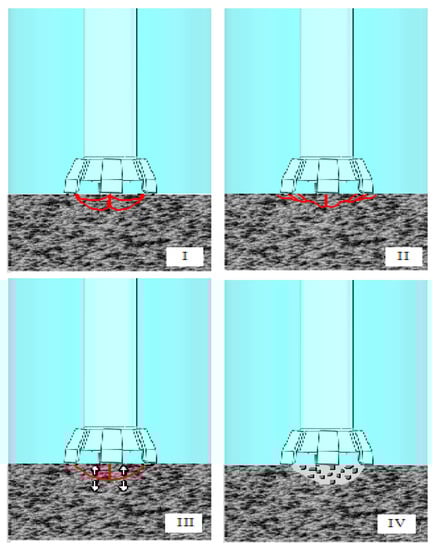
Figure 1.
Rock-breaking process of high-voltage EPB: I electric breakdown of rock; II formation of discharge precursor; III formation of main discharge channel; IV fragmentation of rock.
4. Damage Model of High-Voltage EPB in Granite
The complete damage model of high-voltage EPB in granite includes the shockwave model of high-voltage EPB in granite and the damage model of high-voltage EPB in granite, based on PFC2D.
4.1. The Shockwave Model of High-Voltage EPB in Granite
(1) Equivalent Loop Equation
The Marx generator, of the capacitive energy storage type, is often used in high-voltage EPB [11]. A schematic circuit diagram of Marx generator is shown in Figure 2. A pair of thyristors is used to adjust the charging voltage. High voltage direct current is generated after the voltage being boosted by the transformer and rectified by the rectifier [25]. When the high-voltage pulse switch is disconnected, each storage capacitor is charged using a high-voltage DC charging power supply in parallel. When the high-voltage pulse switch is closed, all storage capacitors will be connected in series, and high voltage on multiples of the number of storage capacitor will be established. Eventually, a high-voltage pulse with a certain pulse width will be generated on the load. The synchronization performance of the Marx generator is determined by the synchronization of the high-voltage pulse switch [26,27].
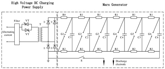
Figure 2.
Circuit schematic diagram of a Marx generator: VT—thyristor, T—transformer, D—rectifier, R0—isolation resistance, R1—charge resistance, R2—protection resistor, G1,G2,G3,G4,G5,G6—spark gap, C1,C2,C3,C4,C5,C6—storage capacitor, S—high-voltage pulse switch.
The equivalent circuit of rock breakdown using high-voltage electro pulse discharge is a typical RLC discharge circuit [28], as shown in Figure 3. The circuit resistance Rz includes the resistance of capacitors, connecting wires, and the high-voltage pulse switch. The inductive inductance L includes the inductance of the capacitors, connecting wires, and discharge channels.
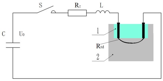
Figure 3.
Equivalent circuit of high-voltage electro pulse breakdown: 1—water medium, 2—rock, C—storage capacitor, S—high-voltage pulse switch, Rz—circuit resistance, L—inductive inductance, Rtd—resistance of plasma channel.
When the high-voltage pulse discharge occurs, the energy in capacitor pack of the Marx generator is released into the plasma channel and converted into energy of other forms. The scheme of generator energy conversion is shown in Figure 4 [11,15]. The total energy of generator Wg is mainly consumed as resistance loss in the electrical circuit WR and forms the energy injected into the plasma channel Wtd. The energy injected into the plasma channel Wtd is converted to heating energy of the plasma channel Wpl and shockwave energy Wws. The shockwave energy Wws is converted to internal energy of rock Wde, kinetic energy Wke and reflected wave energy Wwj.
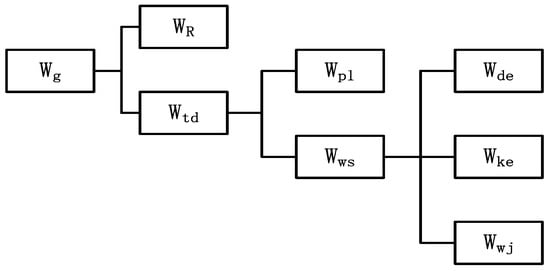
Figure 4.
Scheme of generator energy conversion: Wg—total energy of generator, WR—resistance loss in electrical circuit, Wtd—energy injected into the plasma channel, Wpl—heating energy of the plasma channel, Wws—shockwave energy, Wde—internal energy of rock, Wke—kinetic energy, Wwj—reflected wave energy.
According to Kirchhoff’s loop rule formula, the following equation can be obtained:
where i is the current in the loop and Uc is the instantaneous voltage of the capacitor. The energy storage capacitance, C, exists as:
By calculating the integral of the two sides of Equation (2), the direction of the charge voltage, U0, on the initial capacitor is opposite to the discharge voltage. Therefore, it can be concluded that:
The plasma channel adopts a Weizel–Rompe model of impedance [11,12], which can be expressed in the form of a current integral:
where Ktd is the resistance coefficient and ltd is the length of the plasma channel. Equation (5) can be obtained by substituting Equations (4) and (3) into Equation (1), then differentiating the two sides of the equation. It can be concluded that:
Set:
The second-order differential equation can be simplified into a system of first-order differential equations. From the system of Equations (6), it can be concluded that:
The initial conditions of the equations are as follows:
The power injected into the plasma channel is discretized and integrated. The energy injected into the plasma channel, Wtd, can be expressed as:
The system of Equation (7) is a rigid system, which can be solved numerically using the numerical method of differential equations with variable order. The current of plasma channel, I, and the energy value injected into plasma channel, Wtd, can be obtained. In the process of simulation, the values of the charge voltage, U0, were 10 kV, 15 kV, 20 kV, and 30 kV. The value of capacitance, C, was 0.5 μF, 0.8 μF, 5 μF, and 8 μF. The discharge circuit parameters refer to the high-voltage pulse power supply of a TP3080 series (China Teslaman High-Voltage Power Supply Co., Ltd., Dalian, China), which has a maximum output voltage of 40 kV [22,29]. The electrical circuit resistance, Rz, was 1Ω, the inductance L was 5 μH, and the resistance coefficient Ktd, was 611 V•S1/2/m [11]. It was assumed that the length of the plasma channel was equal to the spacing between the electrodes, and the spacing value was set to 33 mm.
(2) Energy Conservation Equation
According to the principle of energy balance, the energy of the Marx power supply is injected into the plasma channel, and the energy of the plasma channel is converted into heating energy of the plasma channel and shockwave energy during expansion of the plasma channel. An energy conservation equation can be obtained as follows [15]:
γ in the formula refers to the equal entropy index. The distribution of shockwave energy and heating energy in the plasma channel is determined by the entropy index. For condensed materials, the value ranges from 1.05 to 1.25, and the value in this model was 1.1 [15]. P is the shock wave pressure generated during expansion of the plasma channel, and Vtd is the volume of the plasma channel.
(3) Momentum Conservation Equation
The Kratal cylindrical channel model [30,31] is used in the plasma channel model of electrical breakdown. The cylindrical plasma channel model formed by the discharge is shown in Figure 5, where r is the radius, ltd is the length of the plasma channel.
Figure 5.
The cylindrical plasma channel model.
For rock solids, the plasma channel generated by electric breakdown in the solid can be regarded as an expanding cylindrical piston. According to Rankine–Hugoniot's discussion on the shock front [30], a simple relationship between velocity of the channel wall and pressure of the channel surface can be obtained as follows:
where the density of granite, ρ0, is 2660 kg/m3; the shock coefficient, α, is 3.001 × 10⁸ Pa; and β is 3.0 × 10⁸ Pa [30]. By substituting the solved Wtd and Equation (10) into Equation (11), we obtain:
The shock wave pressure, P, produced by the plasma channel expansion can be expressed as:
Equation (12) can be solved numerically using the Euler method. Then, the values of the plasma channel radius, r, and shock wave pressure, P, which vary with time under different electrical parameters, can be obtained.
4.2. The Damage Model of High-Voltage EPB in Granite Based on PFC2D
There are various macro and micro defects in rock, such as holes and cracks, which exert an important influence on rock mechanical properties [32]. Because geotechnical engineering involves a variety of geometric objects and a complex mechanical environment, conventional numerical simulation methods, such as finite element method, finite difference method, and block discrete element method, have limitations in the analysis of large deformations and geotechnical failure. The particle flow code discrete element method, as two-dimensional and three-dimensional programs (PFC2D/PFC3D), can conveniently deal with mechanical problems of discontinuous media, embody different physical relations of multiphase media, effectively simulate discontinuous phenomena, such as cracking and separation of media, and accurately reflect the mechanism, process, and results.
4.2.1. Establishment of the Simulation Model and Definition of the Model Material
Interaction between particles in the particle flow discrete element method is described using the particle contact constitutive model, in which the contact bonding model and the parallel bonding model are the most classical [33]. In current research contexts, the parallel bond model is still the most commonly used particle contact constitutive model for the establishment of a fracture in the PFC2D model [34]. The solver used in the simulation analysis of impact crack is fracture.p2fis, which can turn the parallel bond model into fractures.
In order to fully study and analyze the damage mechanism of EPB in granite, surface damage models of EPB in granite with continuous boundary (Figure 6) and internal damage models of EPB in granite with continuous boundary and free boundary (Figure 7) are established, respectively. The minimum radius of spherical particles was 0.4 mm and the maximum radius was 0.6 mm. In theory, the correlation between the fracture depth (H) of the solid and the electrode distance (S) was H = 0.318S [35]. Thus, the plasma channel distance of electro pulse rock breaking in granite was 10 mm from the free surface. The microscopic parameters of the granite particle model in the simulation process are shown in Table 2.
Figure 6.
Surface damage model of EPB in granite.
Figure 7.
Internal damage model of EPB in granite.
Table 2.
The microscopic parameters of granite particle model.
4.2.2. Viscous Artificial Boundary Setting for the Particle Flow Discrete Element
In the simulation calculation of shockwave fracturing, whether discrete element software or finite element software is used, the problem of an artificial truncation boundary should be considered. The dynamic boundary should be set to absorb the shockwave, so as to prevent the shockwave from re-entering the model due to boundary reflection and superposition of the wave, which will result in a simulation error. There are two main methods for the treatment of an artificial truncated boundary. One is a global artificial boundary, which is a precise artificial boundary. According to the mathematical and physical conditions, the exact analytical solutions satisfying the conditions can be obtained, and then corresponding boundary conditions can be worked out, which can accurately simulate the artificial truncated boundary. However, this boundary needs precise boundary conditions, which are not involved in the discrete element software PFC2D. The software does not involve macroscopic constitutive relations and cannot provide precise boundary conditions. Therefore, the global artificial boundary is not applicable. Meanwhile, the local artificial boundary has been studied by many scholars and is relatively mature, in theory. There are viscous boundaries, including the viscoelastic boundary, the axisymmetric time-domain transmission boundary and the absorbing layer boundary. These theories are more mature and widely used [36].
Zhou et al. [37] applied a reaction force for the simulation of the viscous artificial boundary. The method is refined and accurate. On the basis of this, this paper compiles the dynamic boundary using Fish language alone. By traversing the particles in contact with the boundary wall, and giving the boundary particles the opposite force, the process of absorbing seismic waves is simulated. Considering that the PFC boundary is uneven, the boundary adjustment coefficient is added to further accurately solve the viscous boundary conditions. Based on the continuum theory, the equivalent relationship between axial stress and the resultant axial contact force of two-dimensional regular arrangement elements with equal particle size under uniaxial compression [38] is established. The influential factor of boundary particle size is introduced to obtain the viscous artificial boundary conditions, as follows:
Among them, the sum of the contact forces, ∑Fb, on the artificial boundary is the sum of the component forces on the boundary, D is the particle unit diameter, and αb is the influencing factor of the two-dimensional particle size. In order to achieve the best absorbing effect, the particle size influence factor can be adjusted continuously, and the value of αb here was 0.05 [39]. Cb is the wave velocity in the continuous medium, with a value of 4535 m/s [40]. ρ0 is the density of the propagation medium, where the medium is granite, and ub is the vibration displacement of the boundary particle.
5. Results and Discussion
5.1. The Numerical Solution and Discussion of the High-Voltage EPB Shock Wave Model
The parameters of equivalent capacitance, voltage, discharge frequency, and the voltage rise time of the Marx generator with capacitive energy storage directly determine the drilling efficiency and breaking form of the electro pulse. The equivalent capacitance and charging voltage are important parameters in power supply selection, which are analyzed and solved. The electrode spacing was 33 mm. One group of parameters comprised the charging voltage (10 kV) and the equivalent capacitance (0.5 μF, 0.8 μF, 5 μF, and 8 μF). Another group of parameters comprised the equivalent capacitance (0.5 μF) and the charging voltages (10 kV, 15 kV, 20 kV and 30 kV). The variations of the plasma channel current, plasma channel energy, plasma channel radius, and the shockwave of plasma channel expansion, under different electrical parameters, were analyzed. Figure 8a,b shows that the peak current was 101.9 A when the capacitance was 0.5 μF, and the energy injected into the plasma channel was 22.7 J. When the capacitance was 8 μF, the peak current was 1174 A and the energy injected into the plasma channel was 310.2 J. With the increase of capacitance, the pulse width, and peak value of current increase, the discharge time increased, the discharge rate decreased, and the energy injected into the plasma channel via a single discharge increased. The energy of high-voltage pulse power injected into the plasma channel was converted into the energy of the plasma channel heating and the shockwave was formed via plasma channel expansion. The energy and current waveforms of the plasma channel and the mechanism of rock-breaking efficiency under different electrical parameters have been verified by simulation experiments [14] and electro pulse concrete breaking via experimental investigation [15]. According to the numerical calculation of the plasma channel radius waveform (Figure 8c) and plasma channel expansion shockwave waveform (Figure 8d), it was found that the energy efficiency of the generator energy transformation into wave energy was about 10%. This conclusion is consistent with the conclusion that the energy efficiency of the generator energy transformation into wave energy was 10% to 20% from the breaking prediction model of electric blasting [8]. For a different insulating dielectric between electrodes and fragmented object, conversion efficiency and the correlation coefficients, such as resistance coefficient, are different [15]. The main effect on the conversion efficiency is the equal entropy index. The high temperature of over 3 × 10⁴ K [8] in the plasma channel results in a lower equal entropy index. At this time, most of the energy injected into the plasma channel was used for the formation and maintenance of the plasma channel, and a small part of the energy was converted into shockwave energy. When the stored energy of the Marx generator was injected into the plasma channel, the pressure of the plasma channel reached more than 35 MPa. The shockwave pressure made the plasma channel expand, and the pressure of the plasma channel was not stable. The increase in volume of the plasma channel led to the decrease of the shockwave pressure [18]. At this time, the growth rate of the plasma channel volume became slower. With the increase of capacitance, the peak value of the shockwave increased, the duration of the primary discharge shockwave increased, and the radius of the plasma channel increased.
Figure 8.
(a) Current waveform of plasma channel, (b) the energy injected into the plasma channel, (c) radius of plasma channel, and (d) shock wave. L = 5 μH, U = 10 kV, C (μF): C1 = 0.5, C2 = 0.8, C3 = 5, C4 = 8.
Figure 9a,b show that the peak current was 101.9 A at 10 kV and the energy injected into the plasma channel was 22.7 J. When the voltage was 30 kV, the peak current was 2101 A and the energy injected into the plasma channel was 187.8 J. With the increase in voltage, the discharge current and the energy injected into the plasma channel using a single discharge increased, and the loading rate of the shock wave increased. According to the numerical calculation of the plasma channel radius waveform (Figure 9c) and the shockwave waveform (Figure 9d), the energy efficiency of the generator energy transformation into wave energy was about 10%. With the increase of voltage, the peak value of the shockwave increases but the duration of the primary discharge shockwave decreased and the radius of the plasma channel increased.
Figure 9.
(a) Current waveform of plasma channel, (b) the energy injected into plasma channel, (c) radius of plasma channel, and (d) shockwave. L = 5 μH, C = 0.5 μF, U (kV): U1 = 10, U2 = 15, U3 = 20, U4 = 30.
5.2. The Fracture Process and the Mechanism of the Granite Surface in EPB
When the rising time is less than 500 ns and electrodes are in contact with rock, the high-voltage electro pulse breaks down the rock and produces plasma channels. The energy on the high-voltage capacitor is released into the plasma channels. When the channels are heated, the temperature of the plasma channels rises sharply and a huge pressure is generated, which forces the plasma channels to expand rapidly. Thus, strong shockwaves are generated. The breaking process of the granite surface by electro pulse delivered at different times after loading the shockwave is shown in Figure 10, with relevant electrical parameters U = 10 kV, L = 5 μH, and C = 8 μF. It can be seen from Figure 10 that three zones formed around the plasma channel hole during the propagation of the shock wave of the electro pulse breaking into granite, namely, the comminution zone, the crack zone, and the radial crack zone. Shock waves generated via plasma channel expansion rapidly decayed into stress waves in the rocks. Compressive stress exceeded compressive strength, or the compressive stress of granite was insufficient for crushing materials; however, it can cause disintegration through tensile radial cracks in the area near the plasma channel, thus forming the comminution zones. Granite around the crushing zone will produce annular upward tensile stress under the action of radial compressive stress, radial cracks and crack areas are formed. In the process of stress wave propagation, the crack continues to extend and further expand, forming the radial crack zone. This process is similar to that of rock explosion. Kuznetsova et al. [15] carried out the experimental investigation of electro pulse concrete breaking, and three zones could be clearly seen from the broken concrete. Cho et al. [7] used a high-resolution X-ray computed tomography system to observe the fracture formation, and the existence of three zones was proved.
Figure 10.
Surface cracking and crack propagation of EPB in granite: (a) t = 80 μs, (b) t = 100 μs, (c) t = 200 μs, and (d) t = 400 μs.
Different electrical parameters, different energy of shockwaves, and different forms of cracks in rocks caused by EPB are discussed. As shown in Figure 11, U = 10 kV, L = 5 μH, and C = 0.5 μF, 0.8 μF, 5 μF, and 8 μF. The shockwave of different parameters obtained via analysis and calculation was loaded into the granite. It can be seen from the figure that the larger the capacitance, the larger the peak value of the shockwave and the longer the discharge duration, and at the same time (t = 200 μs, for example), the area of electric pulse breakage and the number of cracks clearly increased.
Figure 11.
Surface cracking and crack propagation of EPB in granite at t = 200 μs, using different capacitances with U = 10 kV: (a) C = 0.5 μF, (b) C = 0.8 μF, (c) C = 5 μF, and (d) C = 8 μF.
5.3. The Fracture Process and Mechanism of Granite Interior in EPB
The breakdown of rock via electro pulse produces the plasma channel, and the expansion of the plasma channel produces the shockwave to break the rock. This process is similar to that of an explosion after drilling holes in rock. As shown in Figure 12, the electrical parameters were C = 0.5 μF, L = 5 μH and U = 15 kV. The calculated shockwave was loaded into the granite, and the internal fracture process involved the granite being broken using electro pulse at different times. It can be seen from Figure 12 that there were also three zones around the plasma channel of the electro pulse breaking granite, namely, the comminution zone, the fissure zone, and the radial crack zone. Without considering the energy loss in the process of EPB (i.e., without considering the hydroelectric effect) only electric crushing was produced, and the shockwave formed under this electric parameter could crush granite.
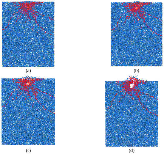
Figure 12.
Interior cracking and crack propagation of EPB in granite, C = 0.5 μF, L = 5 μH, U = 15 kV: (a) t = 80 μs, (b) t = 100 μs, (c) t = 200 μs, and (d) t = 400 μs.
With the increase of voltage, the discharge current and the energy injected into the plasma channel using a single discharge both increased, and the loading rate of the shockwave increased. It can be seen from Figure 13 that the higher the voltage value, the higher the loading rate of the shockwave, and subsequently, the release of pressure near the crack hindered the propagation of cracks, resulting in small cracks while the number of cracks increased. If the loading speed was too fast, the cracks around the plasma channel were very small, perhaps even without cracks. The lower the voltage value, the lower the loading rate of the shockwave, and the number of cracks consequently decreased, resulting in longer cracks. If the loading speed was too slow, a long, hydraulic, fracturing-like crack occurred, resulting in static pressurization. This conclusion is consistent with the research conclusion of Cho et al. [10].
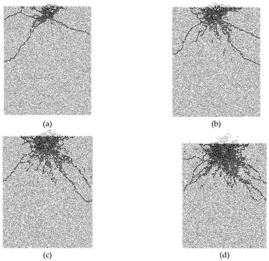
Figure 13.
Interior cracking and crack propagation of EPB in granite at t = 200 μs using different voltages with C = 0.5 μF: (a) U = 10 kV, (b) U = 15 kV, (c) U = 20 kV, and (d) U = 30 kV.
6. Conclusions
In this paper, a complete damage model of high-voltage EPB in granite was established, which included a high-voltage EPB shockwave model and a damage model of high-voltage EPB in granite, based on PFC2D. By using the high-voltage EPB shockwave model, the time-varying waveforms of EPB voltage, current, power, energy, shockwave, and plasma channel radius could be solved numerically, according to different electrical parameters and different electrode-spacing parameters. The damage model of high voltage EPB in granite was based on the particle flow discrete element method, and rock heterogeneity was considered in the rock-breaking simulation analysis. The heterogeneity of rock was the most critical factor affecting rock progressive failure. The damage model of EPB in granite established in this paper could simulate and calculate the whole process of high-voltage EPB, from discharging to producing a shockwave to cracking.
With the increase of capacitance, the pulse width and peak value of the current increased, the discharge time increased, the discharge rate decreased, the energy of the single discharge injected into the plasma channel increased, the peak value of the shockwave increased, the duration of the primary discharge shockwave increased, and the radius of the plasma channel increased. With the increase of voltage, the discharge current and the energy injected into the plasma channel using a single discharge increased, the loading rate of the shock wave increased, and the peak value of the shock wave increased; however, the duration of the shockwave decreased and the radius of the plasma channel increased. The energy conversion efficiency of the generator energy transformation into wave energy by EPB in water was about 10% and the maximum conversion efficiency was not more than 20%.
The process of rock fragmentation using EPB is similar to that of rock explosion. The rock fragmentation using EPB forms three zones around the plasma channel hole, namely, the comminution zone, the fissure zone, and the radial crack zone. With the increase of voltage, the higher the loading rate of the shockwave, and consequently, smaller cracks formed and the number of cracks increased. If the loading speed was too fast, the cracks around the plasma channel were very small, even without cracks. This means that under such extreme conditions, there were no obvious comminution zone, fracture zone, and radial crack zone, and the rock will be directly broken. The lower the value, the lower the loading rate of the shockwave, and the fewer and the longer the cracks.
The damage model of granite in high voltage EPB was established to provide a scientific basis for the quantitative expression and prediction of rock fragmentation in EPB. The numerical experiment and fracture mechanism of high voltage EPB were studied to provide the theoretical and numerical basis for improving drilling efficiency and reducing energy loss during drilling. In further research, an EPB platform will be built to correct the correlation coefficients of the whole theoretical model, which can make the model more accurate. It will inform further theoretical and experimental study of EPB and rock fracture mechanics.
7. Patents
Changping Li; Xianfeng Tan; Longchen Duan; et al. An Electrode drill bit owned multi electrode pair and experimental device of electrical breaking. CHN. Patent 201820098015.X, January 22, 2018.
Longchen Duan; Changping Li; Xianfeng Tan; et al. An electric pulse drill bit of rock breaking and its experimental device. CHN. Patent 201820085807.3, January 18, 2018.
Author Contributions
Conceptualization, L.D. and V.C.; Data curation, C.L. and W.F.; Formal analysis, C.L. and S.T.; Methodology, C.L. and W.F.; Project administration, L.D.; Software, C.L.; Writing–original draft, C.L.
Funding
This research was funded by [National Natural Science Foundation of China] grant number [41672364; 41602373] and [Innovation Fund of Petro-China] grant number [2016D-5007-0307]” and “The APC was funded by [National Natural Science Foundation of China]”.
Acknowledgments
This work was supported by the National Natural Science Foundation of China (41672364; 41602373) and the Innovation Fund of Petro-China (2016D-5007-0307).
Conflicts of Interest
The authors declare no conflict of interest.
Nomenclature
| L | Inductive inductance, H |
| i | Current in the loop, A |
| Rz | Circuit resistance, Ω |
| Rtd | Resistance of plasma channel, Ω |
| Uc | Instantaneous voltage of capacitor, V |
| C | Energy storage capacitance, F |
| U0 | Charge voltage, V |
| Ktd | Resistance coefficient, V·S1/2/m |
| ltd | Length of the plasma channel, m |
| Wg | Total energy of generator, J |
| WR | Resistance loss in electrical circuit, J |
| Wtd | Energy injected into the plasma channel, J |
| Wpl | Heating energy of the plasma channel, J |
| Wws | Shock wave energy, J |
| Wde | Internal energy of rock, J |
| Wke | Kinetic energy, J |
| Wwj | Reflected wave energy, J |
| Vtd | Volume of plasma channel, m3 |
| P | Shockwave pressure, Pa |
| γ | Equal entropy index |
| r | Radius of plasma channel, m |
| α | Shock coefficient, Pa |
| β | Shock coefficient, Pa |
| ρ0 | Density of granite, kg/m3 |
| ∑Fb | Sum of the contact forces, N |
| αb | Influencing factor of two-dimensional particle size |
| Cb | Wave velocity in the continuous medium, m/s |
| ub | Vibration displacement of the boundary particle, m |
References
- Yan, T.; Du, J.Y.; Li, W.; Bi, X.L.; Yao, S.L. Synthesizing Comment on Efficient Rock Fragmentation Method in Frontier Drilling Technology. Oil Field Equip. 2012, 41, 50–55. [Google Scholar]
- Wang, S.; Guo, Y.; Cheng, G.; Li, D. Performance Study of Hybrid Magnetic Coupler Based on Magneto Thermal Coupled Analysis. Energies 2017, 10, 1148. [Google Scholar] [CrossRef]
- Schiegg, H.O.; Rødland, A.; Zhu, G.Z.; Yuen, D. Electro-Pulse-Boring (EPB): Novel Super-Deep Drilling Technology for Low Cost Electricity. J. Earth Sci. 2015, 26, 37–46. [Google Scholar] [CrossRef]
- Cho, S.H.; Mohanty, B.; Ito, M. Dynamic fragmentation of rock by high-voltage pulses. Am. Rock Mech. Assoc. 2006, 6, 1118–1128. [Google Scholar]
- Lisitsyn, I.V.; Inoue, H.; Nishizawa, I.; Katsuki, S.; Akiyama, H. Breakdown and destruction of heterogeneous solid dielectrics by high voltage pulses. J. Appl. Phys. 1998, 84, 6262–6267. [Google Scholar] [CrossRef]
- Li, C.P.; Chikhotkin, V.; Duan, L.C. Research Progress of Electro Pulse Boring Rock Breaking Technology. Geol. Sci. Technol. Inf. 2018, 37, 288–304. [Google Scholar] [CrossRef]
- Cho, S.H.; Cheong, S.S.; Yokota, M.; Kaneko, K. The Dynamic Fracture Process in Rocks Under High-Voltage Pulse Fragmentation. Rock Mech. Rock Eng. 2016, 49, 3841–3853. [Google Scholar] [CrossRef]
- Boev, S.; Vajov, V.; Levchenko, B.; Jgun, D.; Muratov, V.; Peltsman, S.; Adam, A. Electro pulse technology of material destruction and boring. In Proceedings of the IEEE International Pulsed Power Conference, Baltimore, MD, USA, 29 June–2 July 1997; pp. 220–225. [Google Scholar]
- Andres, U.; Timoshkin, I.; Jirestig, J.; Stallknecht, H. Liberation of valuable inclusions in ores and slags by electrical pulses. Powder Technol. 2001, 114, 40–50. [Google Scholar] [CrossRef]
- Cho, S.H.; Kaneko, K. Influence of the applied pressure waveform on the dynamic fracture processes in rock. Int. J. Rock Mech. Min. Sci. 2004, 41, 771–784. [Google Scholar] [CrossRef]
- Burkin, V.V.; Kuznetsova, N.S.; Lopatin, V.V. Dynamics of electro burst in solids: I. Power characteristics of electro burst. J. Phys. D Appl. Phys. 2009, 42, 235–241. [Google Scholar] [CrossRef]
- Burkin, V.V.; Kuznetsova, N.S.; Lopatin, V.V. Dynamics of electro burst in solids: II. Characteristics of wave process. J. Phys. D Appl. Phys. 2009, 42, 242–248. [Google Scholar] [CrossRef]
- Zhang, Z.C. Rock Fragmentation by Pulsed High Voltage Discharge and Drilling Equipment Development. Ph.D. Thesis, Zhejiang University, Hangzhou, China, 6 June 2013. (In Chinese). [Google Scholar]
- Kuznetsova, N.S.; Lopatin, V.V.; Yudin, A.S. Effect of electro-discharge circuit parameters on the destructive action of plasma channel in solid media. J. Phys. Conf. Ser. 2014, 552, 12–19. [Google Scholar] [CrossRef]
- Kuznetsova, N.; Lopatin, V.; Burkin, V.; Golovanevskiy, V.; Zhgun, D.; Ivanov, N. Theoretical and experimental investigation of electro discharge destruction of non-conducting materials. In Proceedings of the IEEE Pulsed Power Conference, Chicago, IL, USA, 19–23 June 2011; pp. 978–984. [Google Scholar]
- Andres, U.; Timoshkin, I.; Soloviev, M. Energy consumption and liberation of minerals in explosive electrical breakdown of ores. Miner. Proc. Extr. Metall. Rev. 2013, 110, 149–157. [Google Scholar] [CrossRef]
- Bluhm, H.; Frey, W.; Giese, H.; Hoppe, P.; Schultheiss, C.; Strassner, R. Application of pulsed HV discharges to material fragmentation and recycling. IEEE Trans. Dielectr. Electr. Insul. 2000, 7, 625–636. [Google Scholar] [CrossRef]
- Lisitsyn, I.V.; Inoue, H.; Katsuki, S.; Akiyama, H. Use of inductive energy storage for electric pulse destruction of solid materials. IEEE Trans. Dielectr. Electr. Insul. 1999, 6, 105–108. [Google Scholar] [CrossRef]
- Kurets, V.I.; Lopatin, V.V.; Noskov, M.D. Influence of local heterogeneities on discharge channel trajectory at electric pulse destruction of materials. J. Min. Sci. 2000, 36, 268–274. [Google Scholar] [CrossRef]
- Andres, U. Development and prospects of mineral liberation by electrical pulses. Int. J. Miner. Process. 2010, 97, 31–38. [Google Scholar] [CrossRef]
- Zuo, W.; Shi, F.; Manlapig, E. Pre-concentration of copper ores by high voltage pulses. Part 1: Principle and major findings. Miner. Eng. 2015, 79, 306–314. [Google Scholar] [CrossRef]
- Yan, F.; Lin, B.; Zhu, C.J.; Guo, C.; Zhou, Y.; Zou, Q.; Liu, T. Using high-voltage electrical pulses to crush coal in an air environment:An experimental study. Powder Technol. 2016, 298, 50–56. [Google Scholar] [CrossRef]
- Sang, H.C.; Yokota, M.; Ito, M.; Kawasaki, S.; Jeong, B.S.; Kim, K.B.; Kaneko, K. Electrical disintegration and micro-focus X-ray CT observations of cement paste samples with dispersed mineral particles. Miner. Eng. 2016, 57, 79–85. [Google Scholar] [CrossRef]
- Biela, J.; Marxgut, C.; Bortis, D.; Kolar, J.W. Solid state modulator for plasma channel drilling. IEEE Trans. Dielectr. Electr. Insul. 2009, 16, 1093–1099. [Google Scholar] [CrossRef]
- Inoue, H.; Lisitsyn, I.V.; Akiyama, H. Drilling of hard rocks by pulsed power. IEEE Electr. Insul. Mag. 2000, 16, 19–25. [Google Scholar] [CrossRef]
- Bortis, D.; Biela, J.; Kolar, J.W. Transient Behavior of Solid-State Modulators With Matrix Transformers. IEEE Trans. Plasma Sci. 2010, 38, 2785–2792. [Google Scholar] [CrossRef]
- Vizir, V.A.; Kovalchuk, B.M.; Kharlov, A.V.; Kumpyak, E.V.; Chervyakov, V.V. High-Voltage Pulsed Generator for Dynamic Fragmentation of Rocks. Rev. Sci. Instrum. 2010, 81, 308–311. [Google Scholar] [CrossRef]
- Li, C.P.; Duan, L.C.; Tan, S.C.; Chiktoykin, V. Influences on High-Voltage Electro Pulse Boring in Granite. Energies 2018, 11, 2461. [Google Scholar] [CrossRef]
- Teslamanhv.com. Available online: http://www.teslamanhv.com/index.php?p=products_show&lanmu=26&id=173&c_id=62 (accessed on 20 October 2017).
- Kratel, A.W.H. Pulsed Power Discharges in Water. Ph.D. Thesis, California Institute of Technology, Pasadena, CA, American, 31 May 1996. [Google Scholar]
- Jiang, J.L.; Lan, S.; Yang, J.X. Numerical Analysis of the Plasma Characteristics of Pulsed Discharge in Water. J. Harbin Univ. Sci. Technol. 2008, 13, 107–111. (In Chinese) [Google Scholar] [CrossRef]
- Park, J.W.; Song, J.J. Numerical simulation of a direct shear test on a rock joint using a bonded-particle model. INT J ROCK MECH MIN 2009, 46, 1315–1328. [Google Scholar] [CrossRef]
- Potyondy, D.O. Simulating stress corrosion with a bonded-particle model for rock. Int. J. Rock Mech. Min. Sci. 2007, 44, 677–691. [Google Scholar] [CrossRef]
- Hazzard, J.F.; Young, R.P. Simulating acoustic emissions in bonded-particle models of rock. Int. J. Rock Mech. Min. Sci. 2000, 37, 867–872. [Google Scholar] [CrossRef]
- Bluhm, H. Pulsed Discharges through Solid and Liquid Dielectrics. In Pulsed Power Systems: Principles and Applications; Springer: Berlin/Heidelberg, Germany, 2006; Volume 10, pp. 254–296. ISBN 3-540-26137-0. [Google Scholar]
- Potyondy, D.O.; Cundall, P.A. A bonded-particle model for rock. Int. J. Rock Mech. Min. Sci. 2004, 41, 1329–1364. [Google Scholar] [CrossRef]
- Zhou, X.T.; Sheng, T.; Leng, X.L.; Fu, X.D.; Cui, Z. Viscous artificial boundary for seismic dynamic time-history analysis with granular discrete element method and its application. Rock Mech. Rock Eng. 2017, 36, 928–939. (In Chinese) [Google Scholar] [CrossRef]
- Thornton, C. The conditions for failure of a face-centered cubic array of uniform rigid spheres. Géotechnique 1979, 29, 441–459. [Google Scholar] [CrossRef]
- Lu, Y.M. Study on Strength Characteristics of Rock Joints under Pre Cyclic Shear. Master’s Thesis, Chongqing University, Chongqing, China, 6 May 2017. (In Chinese). [Google Scholar]
- Banadaki, M.M.D.; Mohanty, B. Numerical simulation of stress wave induced fractures in rock. Int. J. Impact Eng. 2012, 40–41, 16–25. [Google Scholar] [CrossRef]
© 2019 by the authors. Licensee MDPI, Basel, Switzerland. This article is an open access article distributed under the terms and conditions of the Creative Commons Attribution (CC BY) license (http://creativecommons.org/licenses/by/4.0/).