Article

Laser Headlamp with a Tunable Light Field

1
Department of Medicine, Mackay Medical College, 46, Sec. 3, Zhongzheng Rd., Sanzhi Dist., Taipei 25245, Taiwan
2
Graduate Institute of Opto-Mechatronics and Advanced Institute of Manufacturing with High-tech Innovations, National Chung Cheng University, 168, University Rd., Min-Hsiung, Chia-Yi 62102, Taiwan
3
Department of Neurosurgery, Mackay Memorial Hospital, Taipei 10449, Taiwan
4
Department of Applied Physics, National University of Kaohsiung, 700, Kaohsiung University Rd., Nanzih District, Kaohsiung 81148, Taiwan
5
Department of Electro-Optical Engineering, National United University, 2, Lienda, Miaoli 26063, Taiwan
6
Department of Physical Rehabilitation, Kaohsiung Armed Forced General Hospital, 2, Zhongzheng 1st.Rd., Lingya District, Kaohsiung City 80284, Taiwan
*
Authors to whom correspondence should be addressed.
Energies 2019, 12(4), 707; https://doi.org/10.3390/en12040707
Submission received: 28 January 2019 / Revised: 13 February 2019 / Accepted: 21 February 2019 / Published: 21 February 2019

Abstract

:
This study developed an optical module for laser headlamps with a tunable light field. Laser headlamps have high and low beam lighting functions that are applied by changing the numbers of unit headlamps. For regulatory validation, we validated the project in accordance with the Regulation No. 112 of the Economic Commission for Europe (ECE) to determine whether the results meet the regulatory requirements or not. The proposed design increased the lighting distance by 2.14 times and decreased the size of the mechanism by 45% relative to the values for LED headlamps. High and low beam lighting functions were provided by the same laser sources.

1. Introduction

In the past, the reflector of traditional steam headlamps was made up of a parabolic reflector and a lampshade with a complex pattern. With the advancement of technology and the popularity of computers, light source factories can now use computers to design the optical systems of auto lamps. The reflector and lampshade are designed with an accurate bulb illumination model. Through calculation with a computer for many ray tracing instances, we can obtain road lighting computer simulation results. Credibility and the success rate can be improved through an optical design. At present, projected auto, multiple mirror-type auto, and free-form curved surface reflective lamps are available [1]. The usual headlamp lens is made of glass or plastic, and the light of the bulb is projected into a broad, uniform beam through the square mesh above. The lenses of traditional enclosed projection lamps are designed with a round shape to achieve uniform illumination. After the halogen bulb was introduced in the 1980s, circular reflectors were replaced by complex cone-shaped reflectors because the beam could be projected by the reflective surface around the bulb but not the lens; thus, the shape of the lampshade need not be round. The headlamp shape is also changed remarkably, and the lampshade can be designed differently as the bulb or reflector changes. Modeling has become the focus of lampshade design.
In the 21st century, headlamp design is expected to be the mainstream trend of vehicle lighting. In addition to the continuous upgrade of functions, modeling design will also be upgraded, and the lighting function will be strengthened. Small, humanized, durable, energy-saving auto lamps that are easy to manufacture improve the overall appearance of vehicles and are the new mainstream trend of auto lamps. Headlamp systems of advanced vehicles (e.g., BMW and Mercedes), such as the “adaptive front-lighting system” (AFS) [2] used in concept vehicles, have been mass-produced. AFS is characterized by its horizontal automatic adjustment function of illumination. It can adjust the illumination angle according to the load weight, driving speed, and slope to maintain the best visual field, thereby avoiding the effect of strong light from opposite vehicles. Different horizontal illumination angles are designed at different driving speeds. When turning around, the headlamp can rotate with the steering wheel to see beyond the road ahead. AFS has been introduced and adopted in major factories around the world, and the global market demand is expected to reach a considerable scale.
In 2008, Tsukamoto et al. proposed a lamp with a high/low beam modulation function. The lamp has two light sources. The main light source has a low beam function, and the sub-light source is reflected by the shutter to obtain a light field that is compatible with the basic light field; hence, when the two light sources are turned on simultaneously, the lamp has a high beam function [3]. In 2013, Sekiguchi et al. proposed a lamp with an increased illumination area, and an opening was designed in the middle of the lamp shutter. Part of the light passes through the opening to increase the illumination on the upper side of the detection screen, and the area of the reflector is then increased, thereby extending the original lighting area [4]. In the same year, Tajima et al. proposed a lamp for increasing the illumination area. The lamp includes a reflector with different curvatures and a shutter with a stepped structure, and the light is reflected by the reflector to different positions. In this design, a wide illumination area can be projected [5]. In 2015, Yamamoto et al. proposed a lamp with a complex lighting function. The reflector of the lamp module has reflective surfaces with different curvatures and can reflect light to different illumination positions to obtain an additional illumination area. Light sources are also placed on the other side of the reflective surface to provide an additional lighting function for the lamp module, such as daytime running light [6].
Analysis of these previous works shows that researchers mostly focused on the auto lamp of the illumination area, followed by the modulating function of low/high beams. These two parts are the main fields of current automotive lamp patents. However, increasing the illumination area leads to many limitations in the design of auto lamps. Therefore, subsequent studies have focused on the modulating function of low/high beams. In terms of light source choice, LED has been widely used as a lighting source in the auto lamp market, and a wave of using lasers as an illumination source has recently emerged [7,8,9,10,11,12,13,14]. Laser headlamps have most of the advantages of LED headlamps, such as fast response, low brightness attenuation, small size, low energy consumption, and durability. Compared with LED headlamps, laser headlamps have an advantage in volume. The length of a single laser diode can be 10 microns, which is only 1/100 of the size of the conventional LED component. This condition means that the headlamp size can be remarkably reduced, and this reduction is expected to bring a revolutionary change to headstock design. Another crucial advantage of laser headlamps is luminous efficiency. According to the BMW manufacturer, the luminous efficiency of a typical LED illuminator can reach 100 lumens per watt, whereas that of a laser diode can reach 170 lumens per watt. In actual applications, the illumination distance is more than twice that of traditional LED. Under similar lighting conditions, the energy consumption of laser headlamps can be less than 60% of the energy consumption of LED headlamps. This work takes advantage of the laser light source to design a lamp module with a tunable low/high beam function.

2. Design Principle and Development Trend of Laser Headlamps

At present, the basic light source of blue or near-ultraviolet laser diodes and yellow or red, green, and blue mixed phosphors can produce a corresponding white light. In 2013, Kristin et al. explored the production of three kinds of laser light and their luminous efficiency [15]. The first is a kind of white light mixed with red, green, and blue fluorescent powder at a ratio of 1.65:1:3.45 and excited by a near-ultraviolet (wavelength of 402 nm) laser diode called RGB1. The second one is a kind of white light mixed with red, green, and blue fluorescent powder at a ratio of 3.3:1:2.3 and excited by a near-ultraviolet (wavelength of 402 nm) laser diode called RGB2. The third one is a yellow YAG:Ce phosphor excited by a blue light (wavelength of 442 nm) laser diode. The authors pointed out that the white light of yellow YAG:Ce phosphor powder excited by blue light has a lower Ra value and better luminous flux and efficiency than the two other methods [15]. In consideration of discarding the color rendering index in illumination application, the blue light source is selected to excite YAG:Ce to obtain white light because it has high luminous efficiency. Nowadays, LED technology is becoming increasingly advanced, and many auto manufacturers are looking for next-generation light sources. Laser is the most advanced technology at present. Audi, BMW, and other automakers have successively used laser headlamps in their cars.
In 2011, BMW began to study the application of laser headlamps in civilian vehicles. The numerous advantages of laser headlamps make them extremely attractive. BMW officially announced the mass-production model of i8 in Frankfurt in September 2013. i8 is equipped with a new laser light. This laser light can halve the energy consumption, increase brightness, and is compatible with i8, which emphasizes energy efficiency. It also addresses the urgent need for energy saving and environmental protection. This laser headlamp on i8 is merely the beginning, and BMW plans to deploy this technology in other automobiles [16,17]. In 2014, Audi introduced R8 LMX equipped with a laser headlamp through a new matrix laser illumination technology that projects the beam onto the pavement through a group of electromechanical micro-optics systems that can be moved quickly and designed with a silicon component [18]. At a low driving speed, the light beam is distributed to a large projection area, thereby covering a wide range of road ahead. At a high driving speed, the aperture angle of the laser beam is reduced, and the intensity of the light source and the range of illumination are increased considerably in synchronization, which is particularly helpful when driving on highways [18,19].
Laser headlamps will be developed with multi-functionality and intelligent control in the future. In terms of versatility, laser headlamps are likely to be optically designed due to the small size of laser diodes. With an optical design, a laser headlamp is no longer limited to a single function, and daytime running light, direction light, and fog light will be integrated into a single light module in the future to provide increased car space. In terms of intelligent control, given that computing speed has been increasing continuously, computers can now show the car light signal in real time under different road conditions, and a headlamp can produce a corresponding light field that is featured by the instant lighting of the laser diode. The modulation speed of the light field is not hindered. In the coming years, this kind of auto lamp will provide drivers a safer driving environment that the one at present.

3. Model Establishment and Optical Calculation of the Laser Headlamp

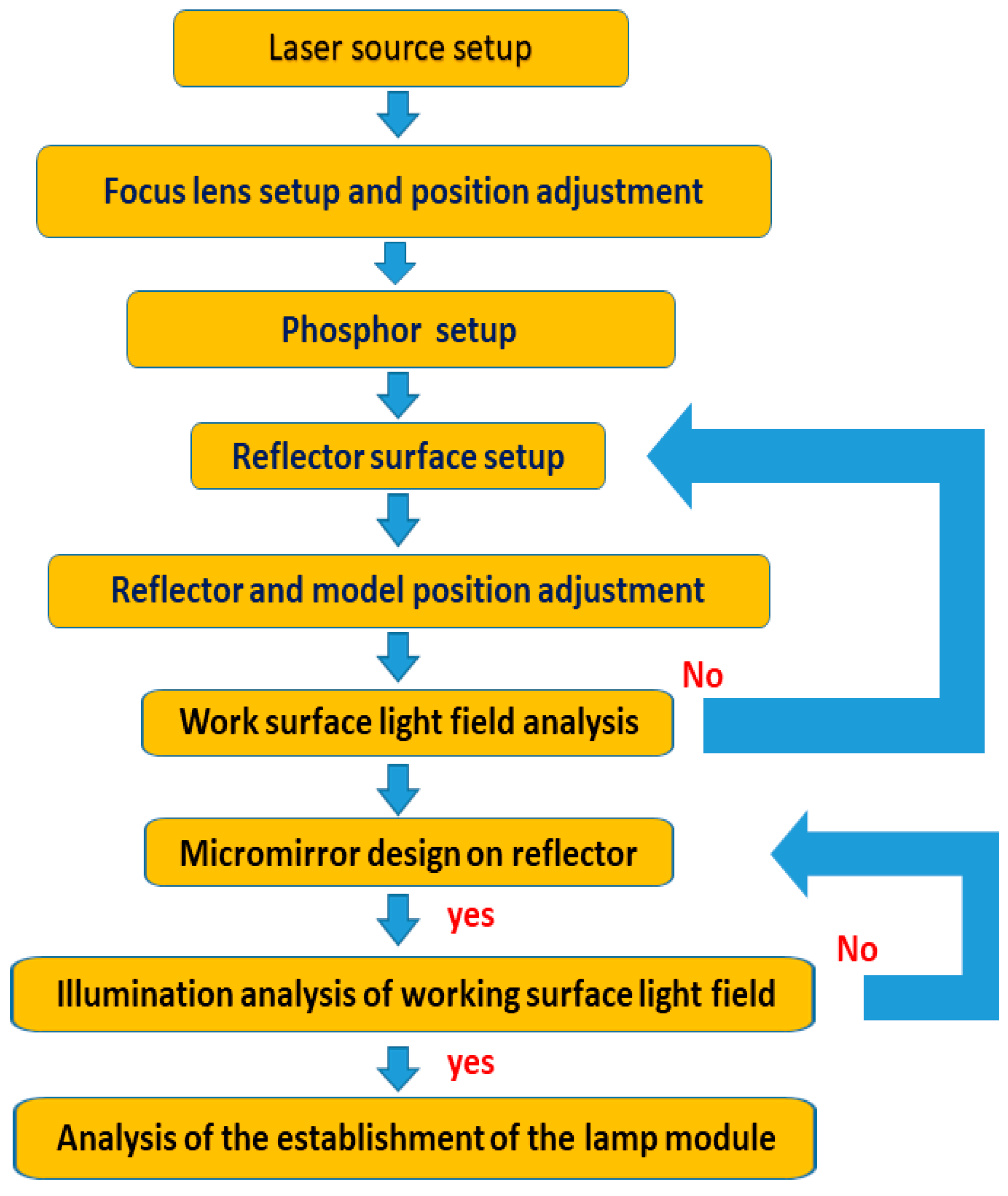
3.1. Optical Design and Analysis Process of Laser Light

In terms of designing the laser headlamp architecture, first, we must consider the construction of headlamps, including the light source, phosphor, and reflector. Second, we should adjust the direction of the reflector to reflect the light to the work plane completely. Third, we should analyze the shape of the light field on the work plane to determine if it conforms to the specification of the ECE R112 near-light field shape [20,21]. If the light field fails to satisfy the light field shape specification, the reflection surface must be redesigned. Fourth, we should design a micro mirror on the reflector to meet the illumination value of each measurement point in ECE R112. Fifth, we should build and analyze the lamp module and use multiple modules to build a complete lamp system for the headlamp to satisfy high beam specifications and the size of the low beam field. Then, we should have a complete lamp module. The process of simulation and analysis is shown in Figure 1.

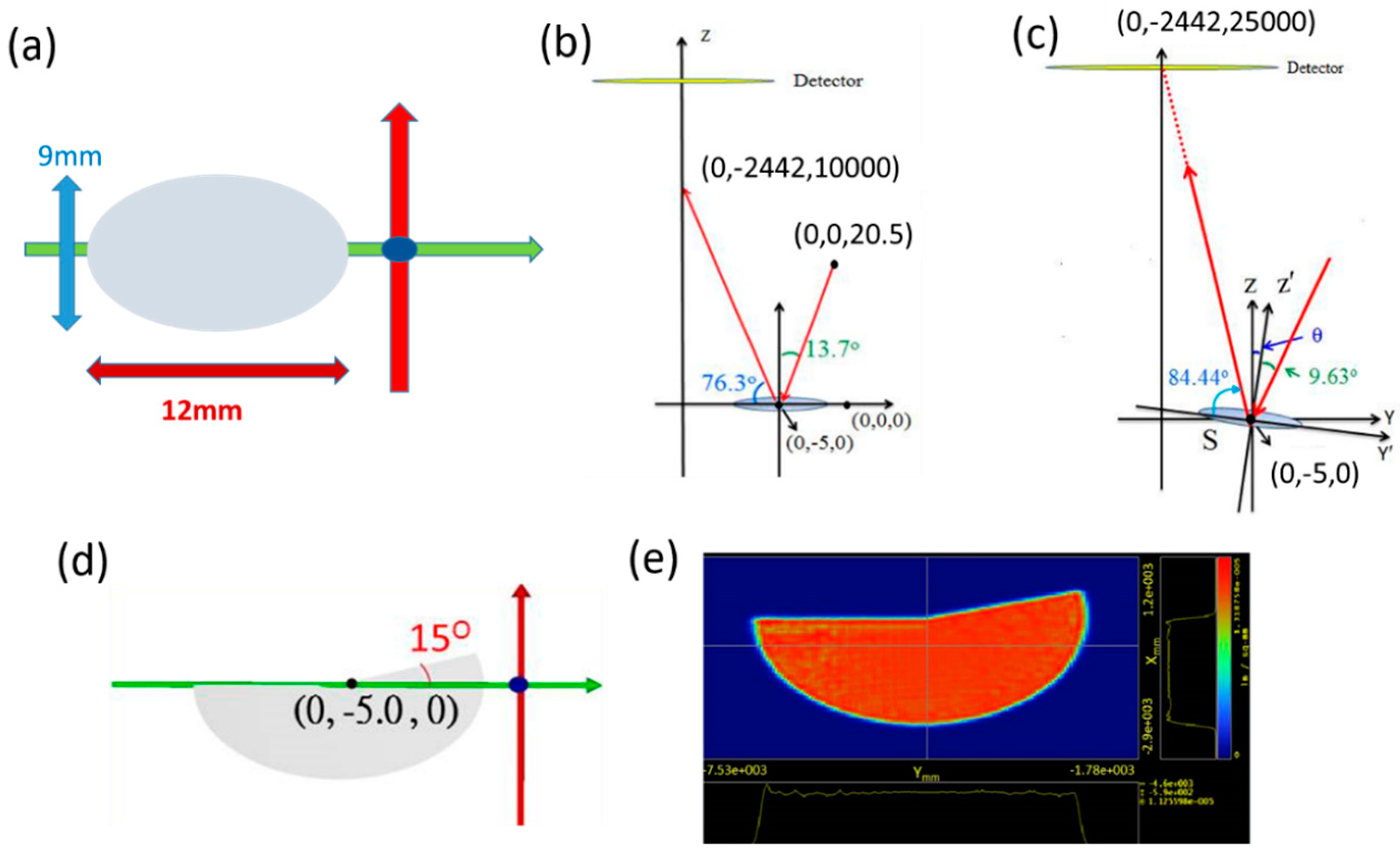
3.2. Setup of the Light Source and Phosphor Model

The white light of this study is generated by a neon laser that excites a yellow phosphor. In the selection of a laser light source, we use the laser diode of model PL450B in the OPTO series of OSRAM, which is 460 nm in wavelength, 3.08 mm in diameter, and 2.8 mm in height [22]. In the selection of phosphor, we use YAG:Ce (Y3Al5O12:Ce3+) in the study of Kristin et al as the basic model of phosphor [15]. The white light generated by the phosphor has a luminous flux of 252 lumens and a luminous efficiency of 76 lumens per watt. This light is suitable for use as a headlamp illumination source because of its high luminous efficiency. When the phosphor is excited by light with a wavelength of 460 nm, the refractive index is 1.809 and the absorption coefficient is 0.383 cm−1. In terms of volume, we refer to the phosphor used in the BMW i8 laser headlamp, as described in [23], and the volume is defined as 3 × 3 × 1 mm3.

3.3. Design Concept of the Reflector

The design processes of the 3D reflector is complicated. Hence, we created a reflector from a conic curve in a rotationally symmetric way. The conic surface graph shows that each curve has a corresponding focus and different curved surfaces can be determined by the sag equation [24,25,26], which is shown in Equation (1). A conic constant comparison table of each conic curve has been provided by [24].
Z = sag ( r ) = r 2 R 1 + 1 ( 1 + k ) r 2 / R 2
where r 2 = x 2 + y 2 , R is the radius of curvature, z is the height difference of the Z axis, and k is a conic constant. If the conic constant is k = −1 and the light source is placed in focus, the light reflected back from the reflector will form a parallel beam. A reflector with a cone constant of 0 < k < −1 will have a light gathering effect, the light emitted from the focus of the mirror with a conic constant of k < −1 will be divergent, and the light of a reflector with a conic constant of k = 0 will be reflected back to the focus [24]. These results indicate that when the light source is at the focal point of the reflector with a conic constant of k < −1, divergent light can be generated. Therefore, we set the conic constant of the reflector as −2 with an elliptical shape, a long axis of 12 mm, and a short axis of 9 mm, as shown in Figure 2a. To ensure that all the light can be reflected by the reflector to the work plane at 25 m, reflector S is placed on the XY axis, and the light is reflected by reflector S to the coordinates (0, −2442, 10,000), as shown in Figure 2b. When the reflector is rotated to the Y-axis by −4.07° based on the law of reflection, the light can be irradiated onto the work plane of the coordinates (0, −2442, 25,000), as shown in Figure 2c. From the figure, we determined that the reflector is designed with a cone constant of −2, and the material is aluminum with a reflectivity of 0.9204. The above steps are for the design of the reflector with high beam function. Then, we design the reflection surface for low beam function. In this step, we only consider the shape of the light field specified in ECE R112 and not the size of the light field. In ECE R112, the low beam field must have a light/dark cut-off line that divides the light field into upper and lower sides. The upper side is a dark area whose function is to prevent drivers from being dazzled by oncoming vehicles. The lower side can illuminate the pavement. The cut-off line is in the middle of the light field. The left half of the line is horizontal, and the right half is straight with an inclined horizontal line of 15°. According to the above regulations, we cut the elliptical shaped reflector. The left side is cut from the middle horizontal line, and the right side is cut from the straight line with an inclined horizontal line of 15°. The cut shape is shown in Figure 2d. The map of the light field that is irradiated onto the work plane is shown in Figure 2e. Therefore, when the lamp is operated in the low beam mode, its reflector is as shown in Figure 2d. When it is switched to the high beam mode, another reflector is added by the moving device to form an elliptical reflector, as shown in Figure 2a.

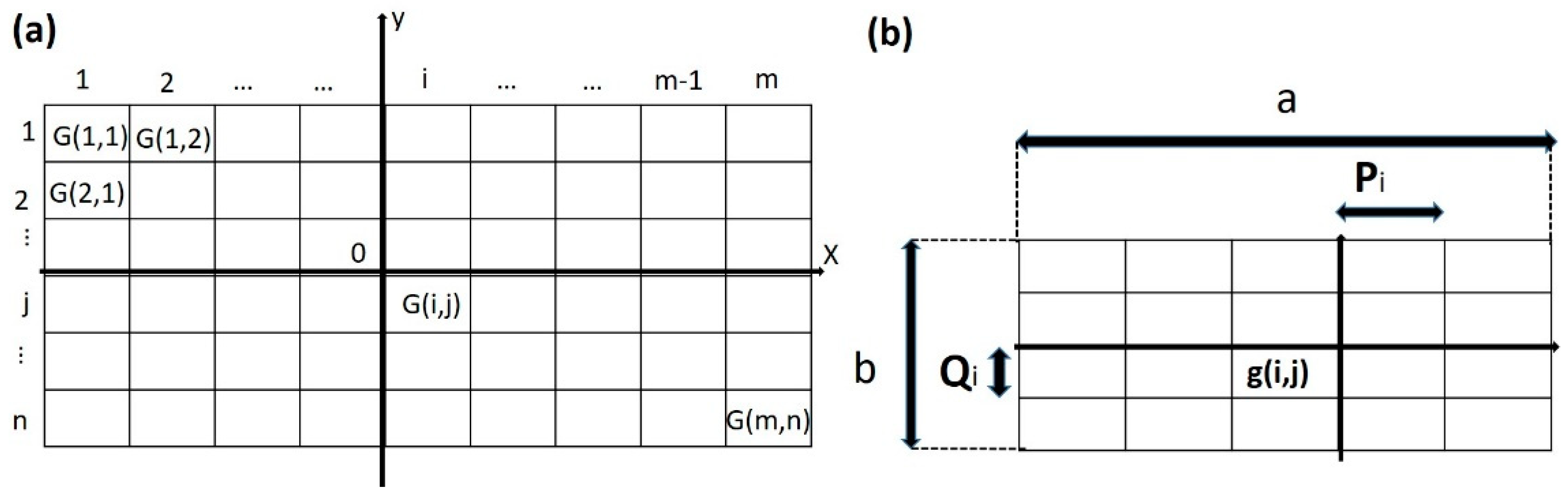
3.4. Design of the Micro-Mirror

After the design stage is completed, we project the light onto the work plane (25 m ahead of the headlamp), analyze the preliminary illumination on the light field on the work plane, and compare it with the specification of low beam illumination in ECE R112. We present a comparison table of the measurement results and regulatory illumination points in Table 1. The table shows that the illumination values through the simulation at Points 75R and 50R do not meet the illumination value specified by the regulation. To improve the illumination values of the two points, we must direct the light to Points 75R and 50R by adjusting the light-emitting direction of the micro-blocks on the reflector so that the two-point illumination values can meet the regulatory standards. We identify the reflector block corresponding to Point 75R on the work plane then select a larger block on the reflector as the reference plane to reflect the light onto the work plane. The light field contains Point 75R. According to the energy conservation principle, the product of the reflector area (So) and the illumination value (Eo) of the reflector is equal to the product of the light field area (Sν) of the work plane and the illumination value (Eν) measured at the light field of the work plane, as shown in Equation (2), which is simplified to Equation (3).
E o · S o = E v · S v
E o = E v · t
where t = Sv/So.
Next, we divide the light field into “m” columns and “n” rows, as shown in Figure 3a, where G(i,j) represents the block of the ith column and jth row. Then, the energy Q(i,0) of the ith column is the product of the illumination value (Eν) measured at the light field of the work plane and the area of the ith column, as shown in Equation (4).
Q ( i , 0 ) = j = 1 n E v · k ( i , j ) · S ( i , j )
where k(i,j) is defined as 1. Thus, the work plane light field energy (Q0) is the “m” column energy set, as shown in Equation (5).
E v · S v = i = 1 n Q ( i , 0 )
Similarly, the energy Q(0,j) of the jth row is expressed in Equation (6) and satisfies Equation (7).
Q ( 0 , j ) = i = 1 n E v · k ( i , j ) · S ( i , j )
E v · S v = j = 1 n Q ( 0 , j )
After analyzing the light field energy on the work plane and further examining the reflector, we define the length of the reflector as “a” mm and its width as “b” mm, where “a” and “b” are 1, as shown in Figure 3b. g(i,j) represents the block of the ith column and the jth row, which corresponds to the G(i,j) block on the light field. The length of the g(i,j) block is “pi” and the width is “qi”. Then, the energy Q(i,0) of the ith column of the reflector is equal to the product of the illumination value Eo measured on the reflector and the area of the ith column, as shown in Equation (8).
E o · a · q j = Q ( i , o )
We use Equations (2)–(5) and (8) to solve the simultaneous equation and find the length qi of the ith column. Then, the energy Q(0,j) of the jth row is derived using Equation (9).
E o · b · p i = Q ( 0 , j )
Then, we use Equations (2), (3), (6), (7), and (9) to solve the simultaneous equation and determine the width (pi) of the jth row and the space coordinates of g(i,j) through the values of pi and qi. We obtain the first micromirror whose positions on the XY space coordinates are (−0.49, −4.50), (−0.49, −4.49), (−0.50, −4.49), and (−0.50, −4.50). Then, we define the XY plane of the primary reflector as the base plane and the normal as the principal axis. By rotating the emitting direction of the micromirror, we move the light to the desired illumination position. We rotate the first micromirror by 2.5° in the +X direction for its normal and the normal of the main reflector (e.g., z axis in Figure 3a) to form an angle of 2.5°, thereby completing the design of the first micromirror. Then, we use the above formula to obtain the spatial coordinates of the second micromirror. The positions of the four points on the XY space coordinates are (−0.49, −4.48), (−0.49, −4.47), (−0.50, −4.47), and (−0.51, −4.48). We rotate the second micromirror by 3.0° in the +Y direction for its normal and the normal of the main reflector to form an angle of 3.0°, thereby completing the design of the second micromirror. We build the other micromirrors in the same manner. In the design of the micromirror of 75R illumination value of the compensation measuring point, we use 12 micromirrors to change the direction of light emission and guide the light around Point 75R to Point 75R to compensate for the lack of the illumination value of Point 75R. Then, we measure the illumination value at Point 75R (12.25 lux), which reaches the regulatory standard. We consolidate the spatial coordinates and rotation angles of the 12 micromirrors in Table 2. In the illumination value compensation design of Point 50R, we obtain the space coordinates of the first micromirror at compensation point 50R according to the above formulas, and their positions on the XY space coordinates are (−0.40, −4.05), (−0.40, −4.04), (−0.41, −4.04), and (−0.41, −4.05). By rotating the emitting direction of the micromirror, which moves the light to the desired illumination position, we rotate the first micromirror by 2.5° in the +X direction for its normal and the normal of the main reflector to form an angle of 2.8°, thereby completing the design of the first micromirror. We obtain the space coordinates of the second micromirror with the above formulas, and the positions of the four points on the XY space coordinates are (−0.15, −4.21), (−0.15, −4.20), (−0.16, −4.20), and (−0.16, −4.20). We rotate the second micromirror by 3.0° in the +Y direction for its normal and the normal of the main reflector to form an angle of 3.0°, thereby completing the design of the second micromirror. We build the other micromirrors in the same manner. At compensation point 50R, we use 21 micromirrors for direction adjustment. After adjustment, the illumination value measured at Point 50 is 12.546 lux, which meets the regulatory standards. Then, we consolidate the spatial coordinates and rotation angles of the 21 blocks Table 3. Through the micromirror design, the illumination value of each measuring point of the light field on the work plane is consistent with the illumination value of the measuring point specified in ECE R112. Therefore, we initially complete the design of the single lamp module.

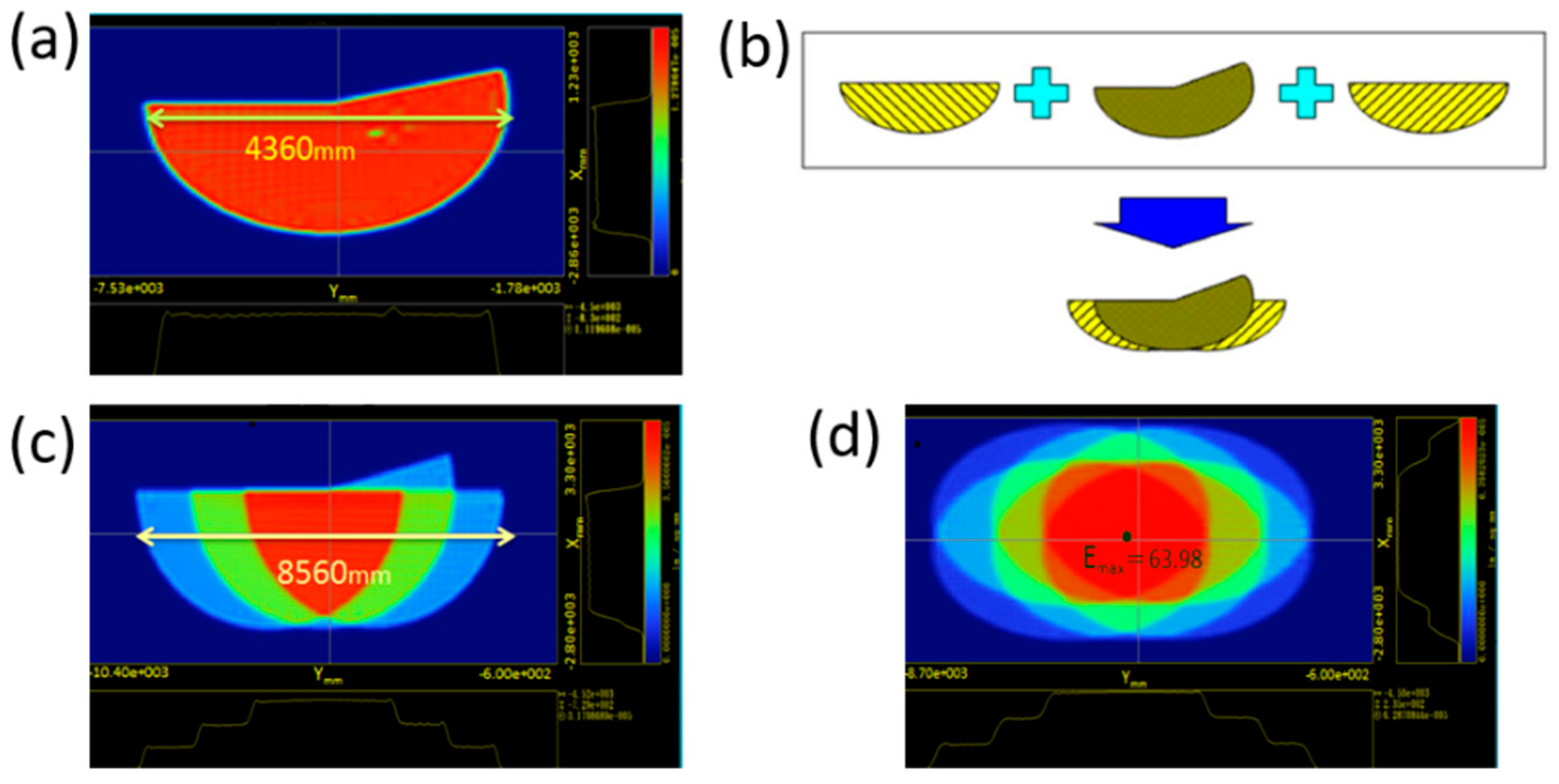
3.5. Setup of the Headlamp System

In this section, we design the light field specification at the low beam mode and the illumination specification at the high beam mode. In ECE R1122, the left and right widths of the low beam should reach 7920 mm. The regulation has no height restrictions. The light field generated by the single lamp module we designed has a width of 4360 mm, as shown in Figure 4a, which is far from the regulatory standards. For the width of the light field to reach the regulatory standards, we use multiple modules to build a complete headlamp system and integrate the multiple light fields into a single light field in a stacking manner, resulting in a light field width of over 7920 mm. The design concept is shown in Figure 4b. Initially, we use three modules for simulation, rank the three modules horizontally, and simultaneously begin to form a group of combined light fields on the work plane, as shown in Figure 4c. The width of light field is 8560 mm, which satisfies the 7920 mm requirement. The low beam system is completed. Next, we design the illumination standard for the high beam. In ECE R112, the illumination field of the high beam must have an illumination value greater than 24 lux in the horizontal ±1125 mm area and greater than 6 lux in the horizontal ±2250 mm area. The maximum illumination value in the light field must be between 48 and 240 lux, and the illumination specification is as shown in Literature [20]. The light field of the high beam lamp we simulated is verified, as shown in Table 4. This table shows that the maximum illumination value and the average illumination value in the horizontal ±1125 mm area do not meet the specifications. Thus, we use the design concept of low beam to correct the illumination by increasing the illumination value in a stacking manner to make it standard. First, we add three headlamp modules in the upper part of the low beam system we just built and use six headlamp modules in this system in high beam mode. The light field diagram is shown in Figure 4d. Second, we analyze the illumination of the light field generated by the system. In terms of the maximum illumination value, the simulation result is 63.98 lux, and the average illumination value of the horizontal ±1125 mm area is 43.17 lux; both meet regulatory requirements. Therefore, we have established a complete lamp system with the function of modulating high and low beams. When operating in the low beam mode, the three lamp modules in the lower half of the lamp system are turned on and operate in the low beam mode. The schematic for this mode is shown in Figure 5a. When operating in the high beam mode, the six lamp modules in the lamp system are simultaneously turned on and operated in the high beam mode. The schematic is shown in Figure 5b.

4. Street Visualization

To demonstrate the real condition for using this laser headlamp, we created an imaginary road space and put the headlamp system in this space. We established roads and road markings in the optical system through traffic road regulations. The refractive index of the raods is approximately 1.55. Figure 6 shows the top view energy distribution and the street visualization with LED and laser headlamps, respectively. We used the high-power white pc-LED that the LED module performance is about 800 lm at 6.5 V – 1 A = 123 lm/W. In Figure 6b,d, the top view energy distribution of the LED headlamp shows 1 lux lines at 276 m less than 592 m of the laser headlamp. In Figure 6a,c, the laser headlamp generated a better lighting filed through street visualization. The system using laser diodes put more light on the road in very interesting ways, such as by employing a layer of phosphorous where several blue laser beams intersect and creating a secondary white light with a potential for luminance that is approximately five times greater than the best current LED headlamps. Thus, the visibility range of the driver can be considerably increased. In automotive applications, this high luminance source allows new functions, such as picture beam, or lighting systems with a very compact output for very thin styling requests.

5. Conclusions

The optical module of the laser headlamp in this study can combine two reflective lenses to form a mirror set in oval shape when the headlamp is operated in the high beam mode. When the headlamp is operated in the low beam mode, the reflective lens at the top portion is moved behind the reflective lens at the bottom portion by the driving member, and only the reflective lens at the bottom can reflect the light to generate the optical field for the low beams. No additional laser light sources or shutters are required in the laser headlamp optical module developed in this study. The design with two reflective lenses can achieve results with high and low beams. In the vehicle headlamp system, six optical modules are used by the optical design, and the vehicle headlamp system can alternately operate in high and low beam modes to meet the illumination standard of high and low beams stipulated in relevant regulations. The energy distribution of the laser headlamp shows 1 lux line at 592 m. This study is characterized by what are presently considered to be the most practical and preferred embodiments. However, this study need not be restricted to the disclosed embodiment. On the contrary, it is intended to cover various modifications and similar arrangements included within the spirit and scope of the appended claims, which are to be accorded with the broadest interpretation to encompass all such modifications and similar structures.

Author Contributions

K.-W.T., T.-H.C., and Y.-D.S. were responsible for finishing data and optical calculations; S.-W.F. and S.-J.C. analyzed laser lighting results; H.-C.W., Z.T.Y., and K.-H.T. organized and wrote manuscript.

Funding

This research was supported by the Ministry of Science and Technology, The Republic of China under the grants MOST 106-2112-M-194-002, 1041B11, and 1052B01 from Mackay Medical College, MMH-MM-10717 from Mackay Memorial Hospital, and Kaohsiung Armed Forces General Hospital research project 106-28.

Conflicts of Interest

The authors declare no conflict of interest.

References

  1. Cvetkovic, A.; Dross, O.; Chaves, J.; Benitez, P.; Miñano, J.C.; Mohedano, R. Etendue-preserving mixing and projection optics for high-luminance LEDs, applied to automotive headlamps. Opt. Express 2006, 14, 13014–13020. [Google Scholar] [CrossRef] [PubMed]
  2. Fang, X.; Yao, Y.; Liu, J. Study on Advanced Front-lighting System of Intelligent Vehicle. Tianjin Auto. 2006, 4, 005. [Google Scholar]
  3. Tsukamoto, M.; Ishida, H.; Sazuka, K.; Tatsukawa, M. Vehicular illumination lamp with primary and secondary light sources. U.S. Patent No. 7,387,416, 17 June 2008. [Google Scholar]
  4. Sekiguchi, T. Vehicle lighting unit. U.S. Patent No. 8,690,405, 8 April 2014. [Google Scholar]
  5. Masahito, N.; Tajima, T. Vehicle headlamp. U.S. Patent No. 7,393,126, 1 July 2008. [Google Scholar]
  6. Yamamoto, I. Lamp unit. U.S. Patent No. 8,425,097, 23 April 2013. [Google Scholar]
  7. Ge, A.; Du, Z.; Wang, W.; Qiu, P.; Wang, J.; Cai, J.; Song, X. A composite optical system for a LED-based headlamp low beam module. Light. Res. Technol. 2013, 45, 752–757. [Google Scholar] [CrossRef]
  8. Qiu, P.; Ge, A.; Wang, J.; Cai, J.; Zhu, L.; Du, Z. Design of an LED-based headlamp low-beam system using combined prisms. Light. Res. Technol. 2015, 47, 248–253. [Google Scholar] [CrossRef]
  9. Hsieh, C.C.; Li, Y.H.; Hung, C.C. Modular design of the LED vehicle projector headlamp system. Appl. Opt. 2013, 52, 5221–5229. [Google Scholar] [CrossRef] [PubMed]
  10. Ge, A.; Wang, W.; Du, Z.; Qiu, P.; Wang, J.; Cai, J. High-energy-efficiency optical system for an LED-based headlamp architecture. Appl. Opt. 2013, 52, 8318–8323. [Google Scholar] [CrossRef] [PubMed]
  11. Ge, P.; Li, Y.; Chen, Z.; Wang, H. LED high-beam headlamp based on free-form microlenses. Appl. Opt. 2014, 53, 5570–5575. [Google Scholar] [CrossRef] [PubMed]
  12. Wang, H.; Wang, X.; Li, Y.; Ge, P. Design of a newly projected light-emitting diode low-beam headlamp based on microlenses. Appl. Opt. 2015, 54, 1794–1801. [Google Scholar] [CrossRef]
  13. Chandrajit, B.; Merve, M.W.; Bernhard, R. Lighting with laser diodes. Adv. Opt. Technol. 2013, 2, 313–321. [Google Scholar]
  14. Whang, A.J.W.; Jhan, K.C.; Chao, S.M.; Chen, G.W.; Chou, C.H.; Lin, C.M.; Chang, C.M.; Chen, K.Y.; Lai, Y.L. An innovative vehicle headlamp design based on a high-efficiency LED light pipe system. Light. Res. Technol. 2015, 47, 210–220. [Google Scholar] [CrossRef]
  15. Denault, K.A.; Cantore, M.; Nakamura, S.; DenBaars, S.P.; Seshadri, R. Efficient and stable laser-driven white lighting. AIP Adv. 2013, 3, 072107. [Google Scholar] [CrossRef] [Green Version]
  16. Weber, S.; Buck, A.; Amann, C. Laser Light in the BMW i8 Design, System Integration and Test. ATZ Worldwide 2014, 116, 44–49. [Google Scholar] [CrossRef]
  17. Ulrich, L. Whiter Brights with Lasers; IEEE Spectrum: New York, NY, USA, 2013; Volume 50, pp. 36–56. [Google Scholar]
  18. Gies, C.; Lorke, M.; Jahnke, F.; Chow, W.W. Quantum-Dot Nanolasers. In Handbook of Optoelectronic Device Modeling and Simulation; CRC Press: Boca Raton, FL, USA, 2017; pp. 627–660. [Google Scholar]
  19. Bhardwaj, J.; Peddada, R.; Spinger, B. Advances in LEDs for automotive applications. In Proceedings of the SPIE Photonics West, San Francisco, CA, USA, 13–18 February 2016; Volume 9768, p. 976811. [Google Scholar]
  20. United Nations Economic Commission for Europe Vehicle Regulations, Reg. 112-Rev. 2. Available online: https://www.unece.org/fileadmin/DAM/trans/main/wp29/wp29regs/R112rev2_e.pdf (accessed on 20 September 2010).
  21. Chen, F.; Wang, K.; Qin, Z.; Wu, D.; Luo, X.; Liu, S. Design method of high-efficient LED headlamp lens. Opt. Express 2010, 18, 20926–20938. [Google Scholar] [CrossRef] [PubMed]
  22. Yang, J. Highly Uniform White Light-Based Visible Light Communication Using Red, Green, and Blue Laser Diodes. IEEE Photonics J. 2018, 10, 1–8. [Google Scholar] [CrossRef]
  23. Hanafi, A.; Erdl, H.; Weber, S. New efficient, compact vehicular lighting system using high-power semiconductor laser diodes. In Proceedings of the DOE Solid-State Lighting RD Workshop, Tampa, FL, USA, 28–30 January 2014. [Google Scholar]
  24. Sacek, V. Notes on Amateur Telescope Optics. Available online: https://www.telescope-optics.net/conics_and_aberrations.htm (accessed on 14 July 2006).
  25. Wang, H.C.; Chiang, Y.T.; Lin, C.Y.; Lu, M.Y.; Lee, M.K.; Feng, S.W.; Kuo, C.T. All-reflective RGB LED flashlight design for effective color mixing. Opt. Express 2016, 24, 4411–4420. [Google Scholar] [CrossRef] [PubMed]
  26. Chen, Y.S.; Lin, C.Y.; Yeh, C.M.; Kuo, C.T.; Hsu, C.W.; Wang, H.C. Anti-glare LED lamps with adjustable illumination light field. Opt. Express 2014, 22, 5183–5195. [Google Scholar] [CrossRef] [PubMed]
Figure 1. Flowchart of the design and analysis of laser headlamp module.
Energies 12 00707 g001
Figure 2. Map of the position of the reflector design: (a) elliptical reflector, (b) light reflected to coordinates (0, −2442, 10,000), (c) light reflected to coordinates (0, −2442, 25,000), (d) reflector in low beam mode, and (e) light field shape on the work plane in low beam mode.
Energies 12 00707 g002
Figure 3. (a) Cutting diagram of light field of the work plane and (b) cutting diagram of the reflector.
Energies 12 00707 g003
Figure 4. (a) Width of the light field on the work plane in low beam mode, (b) conceptual design of the low beam system, (c) diagram of the light field of the low beam system, and (d) diagram of the light field of the high beam system.
Energies 12 00707 g004
Figure 5. (a) System operation diagrams when operating in low beam mode and (b) high beam mode.
Energies 12 00707 g005
Figure 6. Street visualization with (a) LED headlamp and (c) laser headlamp and top view energy distribution of (b) LED headlamp and (d) laser headlamp.
Energies 12 00707 g006
Table 1. Comparison of simulated results at the illumination point of the low beam field with relevant regulations (B50L, 75R, 75L, 50L, 50R, and 50V represent different positions in the illumination area, as shown in ECE R112).
Specification Point LocationRequired (lux)Simulated (lux)
B50L≤0.40.01
75R≥1211.55
75L≤1211.56
50L≤1511.45
50R≥1211.38
50V≥611.44
Table 2. Coordinate positions and rotation angles of the 12 micromirrors used for compensation “Point 75R” illumination.
Number For 75R PointCoordinate Positions of Micromirror on Reflector SRotation Angle
1(−0.49,−4.50)(−0.49,−4.49)(−0.50,−4.49)(−0.50,−4.50)X = 2.5°
2(−0.50,−4.50)(−0.50,−4.49)(−0.51,−4.49)(−0.51,−4.50)X = 2.5°
3(−0.51,−4.50)(−0.50,−4.49)(−0.52,−4.49)(−0.52,−4.50)X = 2.5°
4(−0.49,−4.48)(−0.49,−4.47)(−0.50,−4.47)(−0.50,−4.48)Y = −3.0°
5(−0.51,−4.51)(−0.51,−4.50)(−0.52,−4.50)(−0.52,−4.51)Y = 2.2°
6(−0.51,−4.52)(−0.51,−4.51)(−0.52,−4.51)(−0.52,−4.52)Y = 2.2°
7(−0.51,−4.48)(−0.51,−4.47)(−0.52,−4.47)(−0.52,−4.48)Y = −3.0°
8(−0.51,−4.47)(−0.51,−4.46)(−0.52,−4.46)(−0.52,−4.47)Y = −3.0°
9(−0.50,−4.46)(−0.50,−4.45)(−0.51,−4.45)(−0.51,−4.46)Y = −3.0°
10(−0.50,−4.51)(−0.50,−4.50)(−0.51,−4.50)(−0.51,−4.51)Y = 2.2°
11(−0.49,−4.46)(−0.49,−4.45)(−0.50,−4.55)(−0.50,−4.46)Y = −3.0°
12(−0.49,−4.47)(−0.49,−4.46)(−0.50,−4.46)(−0.50,−4.47)Y = 2.2°
Table 3. Coordinate positions and rotation angles of the 12 micromirrors used for compensation “Point 75R” illumination.
Number For 50R PointCoordinate Positions of Micromirror on Reflector SRotation Angle
1(−0.40,−4.05)(−0.40,−4.04)(−0.41,−4.04)(−0.41,−4.05)X = −2.8°
2(−0.40,−4.07)(−0.40,−4.06)(−0.41,−4.06)(−0.41,−4.07)X = −2.8°
3(−0.40,−4.09)(−0.40,−4.08)(−0.41,−4.08)(−0.41,−4.09)X = −2.8°
4(−0.15,−4.21)(−0.15,−4.20)(−0.16,−4.20)(−0.16,−4.21)Y = −3.0°
5(−0.15,−4.19)(−0.15,−4.18)(−0.16,−4.18)(−0.16,−4.19)Y = −3.0°
6(−0.15,−4.20)(−0.15,−4.19)(−0.16,−4.19)(−0.16,−4.20)Y = −3.0°
7(−0.13,−4.21)(−0.13,−4.20)(−0.14,−4.20)(−0.14,−4.21)Y = −3.0°
8(−0.13,−4.19)(−0.13,−4.18)(−0.14,−4.18)(−0.14,−4.19)Y = −3.0°
9(−0.58,−4.27)(−0.58,−4.26)(−0.59,−4.26)(−0.59,−4.27)Y = −3.7°
10(−0.59,−4.27)(−0.59,−4.26)(−0.60,−4.26)(−0.60,−4.27)Y = −3.7°
11(−0.59,−4.24)(−0.59,−4.25)(−0.60,−4.25)(−0.60,−4.26)Y = −3.7°
12(−0.59,−4.25)(−0.59,−4.24)(−0.60,−4.24)(−0.60,−4.25)Y = −3.7°
13(−0.59,−4.24)(−0.59,−4.23)(−0.60,−4.23)(−0.60,−4.24)Y = −3.7°
14(−0.28,−4.07)(−0.28,−4.08)(−0.29,−4.08)(−0.29,−4.07)X = −2.0°
15(−0.28,−4.08)(−0.28,−4.09)(−0.29,−4.09)(−0.29,−4.08)X = −2.0°
16(−0.28,−4.09)(−0.28,−4.10)(−0.29,−4.10)(−0.29,−4.09)X = −2.0°
17(−0.28,−4.10)(−0.28,−4.11)(−0.29,−4.11)(−0.29,−4.10)X = −2.0°
18(−0.28,−4.11)(−0.28,−4.12)(−0.29,−4.12)(−0.29,−4.11)X = −2.0°
19(−0.28,−4.12)(−0.28,−4.13)(−0.29,−4.13)(−0.29,−4.12)X = −2.0°
20(−0.28,−4.13)(−0.28,−4.12)(−0.29,−4.12)(−0.29,−4.13)X = −2.0°
21(−0.28,−4.15)(−0.28,−4.14)(−0.29,−4.14)(−0.29,−4.15)X = −2.0°
Table 4. Comparison of simulated results and illuminance regulations of the light field in high beam mode.
Specification AreaRequired (lux)Simulate (lux)
Emax240 ≧ Emax ≧ 4812.73
±1125 mm≧2411.54
±2250 mm≧611.13

