1. Introduction
With the depletion of fossil fuel supplies, environmental problems and the energy crisis have become more and more serious. Hydrogen is an energy carrier which can store energy produced by any acceptable way, so hydrogen has a focus for researchers all over the world in recent years. The main problems for the development and the use of hydrogen energy are related to the purification, storage and transportation of the hydrogen. In present, there are many ways to store the hydrogen, such as solid state at low temperature, molecular hydrides [
1], hydride complexes, hydrocarbons, adsorbed layers in porous materials, metal hydrides, liquid hydrogen storage and compressed hydrogen storage and so on. Nowadays, compressed hydrogen storage systems are widely used, thanks to their simple structure and charge-discharge process.
In this article, we mainly conducted research based on high pressure gaseous hydrogen tanks. However, due to safety requirements, the hydrogen temperature must be controlled under 85 °C during the charging process and above −40 °C during the discharge process, and the normal working pressure should not exceed to 125% of the specified pressure of the tank. To address these problems, many experimental and numerical researches have been carried out. The long-term mechanical and thermal behavior and the safety performance of hydrogen tanks during fast filling was investigated experimentally at the Joint Research Centre Institute for Energy and Transport (JRC-IET) [
2]. Experiments on the discharge cycle of compressed hydrogen gas cylinders were carried out, and a model was presented for simulating and describing the thermal behavior during the cycling test, where the effects of ambient temperature and inflow temperature were taken into consideration [
3]. A computational fluid dynamics (CFD) model was developed to simulate the charge process of a type IV tank, which was filled to 70 MPa under different working conditions. The contributions of average pressure ramp rate, adiabatic and cold filling to the maximum hydrogen temperature were investigated [
4]. Several charging experiments on a type III tank were conducted to study the temperature rise during fast filling, and the result pointed out the location of the maximum hydrogen temperature. The validity of the experimental results was compared with the CFD results [
5]. Herein, two types of tanks are considered, one is Type III with a volume of 40 L (with a metallic liner), and the other is a Type IV with a volume of 29 L (with a plastic liner). Numerical analysis of the flow and temperature characteristics is presented for a hydrogen refueling station [
6]. Experiments are done to evaluate the hydrogen temperature inside a tank during a filling with highly-pressurized gas [
7]. The effect of the initial temperature of the on-board hydrogen tank on the final hydrogen temperature and the final state of charge is presented [
8]. The temperature change in practice hydrogen pressure tanks is estimated with filling the tank at the final pressure of 35 MPa and 70 MPa [
9].
Recently, a lumped parameter model was presented to study the thermodynamic behavior of a compressed hydrogen storage system, and an approximate analytical solution was thus obtained [
10], which was used to determine the hydrogen temperature for a 35 MPa tank during fast filling [
11], and extend it to a 70 MPa tank [
12]. The final temperature and mass of compressed hydrogen in a tank after a refueling process can be estimated using the analytical solutions of a lumped parameter thermodynamic model of a high pressure compressed hydrogen storage system [
13]. Filling experiments with different inlet gas temperatures and mass flow rates have been executed using two different types of on-board tanks (Type III and IV) [
14]. Besides, the thermodynamic model can be utilized to deduce the analytical solution of the inflow temperature [
15] and hydrogen mass [
16]. The inflow temperature can guide the hydrogen station to precool the hydrogen in advance.
In this article, a new analytical solution of the final SOC is presented. By applying the mass and energy balance equations, an analytical solution of hydrogen temperature is deduced, then the solution of hydrogen mass is deduced further based on the solution of hydrogen temperature. If the volume of the tank is known, by assuming the hydrogen density inside a tank is uniform, the SOC which defined as the ratio of hydrogen density to the full-fill density can be transformed to be the ratio of filled hydrogen mass to the full-fill hydrogen mass. The hydrogen mass can be calculated by the deduced analytical solution of hydrogen mass, meanwhile the full-fill hydrogen mass is supposed to be a constant value which can be calculated by temperature, pressure and volume of tanks. The investigations on the effects of inflow temperature and mass flow rate on the final SOC are carried out respectively, the analytical solution of SOC can be utilized to fit the corresponding reference data, thus the function relationship between SOC and the refueling parameters can be determined. In addition, a two-parameter effect on the SOC are also investigated. The analytical model is modified with the use of the Nusselt number and Reynolds number. The Nusselt number (Nu) is the ratio of convective to conductive heat transfer across (normal to) the boundary and the Reynolds number is the ratio of inertial forces to viscous forces within a fluid. The analytical model of SOC is useful to meet the safety requirement and sufficient final SOC during the fast filling.
2. Model
In this section, a lumped parameter model based on thermodynamics is proposed to obtain the analytical solution of the final state of charge. As is known, the SOC is defined as the ratio of hydrogen density during refueling to the full-fill density. If the volume of tank is given, with the assumption that the hydrogen density inside the tank is uniform, the SOC can be calculated as the ratio of hydrogen mass to the full-fill mass. The full-fill density of 35 MPa and 70 MPa tanks at 15 °C are respectively 24.0 g/L and 40.2 g/L, i.e., the full-fill mass of the tank is supposed to be a constant, so if the hydrogen mass could be determined from the refueling parameters, the function relationship between SOC and refueling parameters could also be obtained. To address this issue, a lumped parameter model is presented in the paragraphs that follow [
9,
13]. The mass balance equation of compressed hydrogen storage system can be written as follows:
where
and
are respectively the mass flow rates in which the hydrogen flows into the inlet and out of the exit of the hydrogen tank. The energy balance equation can also be written as:
Similarly,
and
are the specific enthalpy of inflow and outflow hydrogen respectively.
is the heat inflow rate which can be written with Newton’s law of cooling:
. Herein, we have
and
for the charge process,
and
for the discharge process, thus, Equations (1) and (2) can be simplified to be as follows:
In order to conveniently obtain the analytical solution of the model, it is assumed that the flow rate is a constant value, with initial condition of
at
, the solution of mass balance equation is
. Submitting this solution into the energy balance equation, it is obtained that:
Defining
,
, Equation (5) can be rewritten as:
where
,
,
,
. Equation (6) is a differential equation on the hydrogen temperature. With the initial condition of
at
, its solution can be obtained as follows:
Equation (7) is the analytical solution of the hydrogen temperature, which can be written in the following form:
where
is the modified initial mass fraction,
,
.
For the initial and final states of refueling procedure, using ideal gas equation of state, we have
and
, divided the former equation by the latter one, we obtain
where
is the ratio of final pressure over initial pressure. For simplification, we use
from Equation (9) to approximate
in Equation (8) and thus obtain:
Reusing Equation (9) in the form
, and combining this new equation form with Equation (10), we can obtain final hydrogen mass:
where
.
Dividing Equation (11) by the full-fill mass, we can obtain the analytical solution of the SOC:
Using this analytical solution, we can express the final SOC by other refueling parameters, i.e., SOC can be different functions of refueling parameters.
3. Results and Discussions
In this section, we use our model to express the reference data (simulated or experimental data), and in return, the fitting results are utilized to check the validity of our model. We study two kinds of hydrogen tanks with a nominal working pressure of 70 MPa, one is a Type III tank (40 L), and the other is a Type IV tank (29 L). As stated above, the full-fill density of 70 MPa tank at 15 °C is 40.2 g/L, so the full-fill mass for these two tanks are 1.608 kg (Type III) and 1.1658 kg (Type IV), respectively. From [
14], the initial pressure
for the two tanks is set as 2 MPa, and both tanks are filled up to a final pressure
of 77–78 MPa, the ambient temperature
is controlled at 291–300 K. Herein, the initial temperature
inside tank is considered to be the same as the ambient temperature.
3.1. Effect of Inflow Temperature on SOC
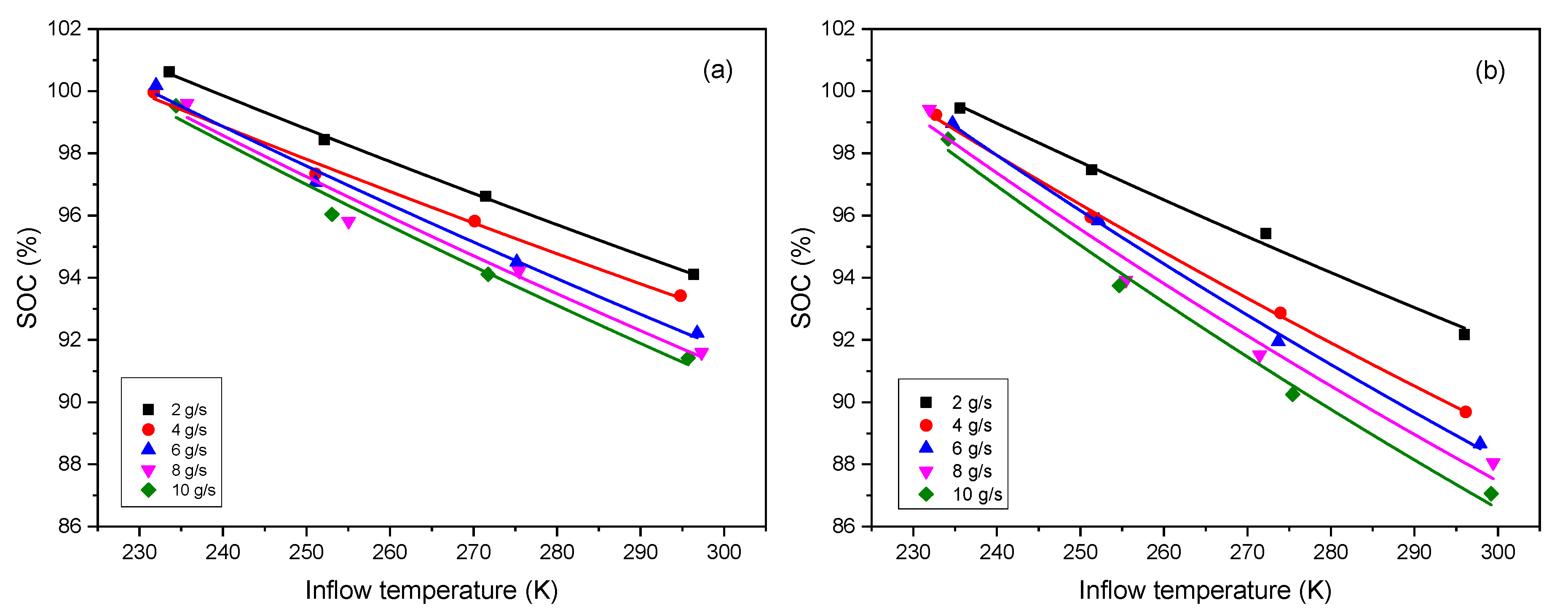
The effect of inflow temperature on SOC under five different mass flow rates of 2, 4, 6, 8 and 10 g/s is presented. Equation (9) can be written in the following form:
Herein, we have
J/K/kg,
K,
MPa. We fix
. According to the definition of
, the value of
is supposed to be
. However, the analytical solution is deduced based on the ideal gas equation of state, in fact, the behavior of hydrogen during the refueling process is far away from the one of an ideal gas. If taking consideration of a compressibility factor
into the equation of state,
, we can obtain a new form of Equation (9), i.e.:
where
,
K/MPa [
17]. Since
, it can be found that
, i.e., the value of
can be modified to be a smaller one in this way. If another method is used, such as the Redlich-Kwong equation, we can obtain another small
. Considering different ways to deal with the equation, various values of
can be obtained, thus,
can be set as a variable parameter in the Equation (13). Besides,
is another unknown parameter. Both of them are set as the fitted parameters. Equation (13) is utilized to fit with the reference data [
14], the results show a good agreement as shown in
Figure 1, and the values of fitted parameters are listed in
Table 1.
As seen from Equation (13), the variation of SOC with inflow temperature is an inverse proportional function, but the fitting shows a linear trend. The explanation is as follows: a series expansion gives , when . Applying this result to Equation (13), we have , where , , , so we can obtain that . This is the reason why the fitting shows a linear trend.
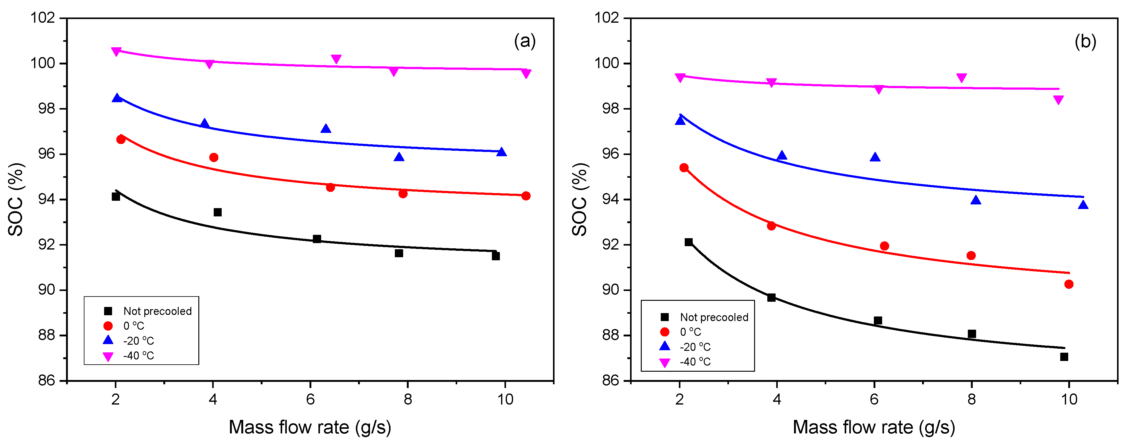
3.2. Effect of Mass Flow Rate on SOC
The effect of mass flow rate on SOC under different inflow temperatures of
,
, 0 °C and not precooled is presented. Herein, according to the definition of
, we can use
(
, and
expressed in the unit g/s here for source data of fitting) in the Equation (12). Like in
Section 3.1,
is also set as a fitted parameter, and
is the other one. As shown in
Figure 2, the deduced formula can express the reference data very well.
Table 2 shows the values of the fitted parameters, where the non-precooled temperature is same as the ambient temperature.
Inflow temperature and mass flow rate are the key factor when investigating the contribution of refueling parameters to the SOC, and both have a negative influence on the SOC. The higher the inflow temperature is, the less the SOC is, and so is the mass flow rate. Given that the inflow temperature is low, it means the hydrogen gas has been precooled in advance, under a certain limited final temperature (e.g., 85 °C, the upper temperature limit stipulated in SAE J2601), the tank is supposed to be filled with more gas. Supposing that the mass flow rate is high, meaning the tank is charged very fast, it leads to the heat exchange between the gas and environment being slow, and the hydrogen temperature inside tank easily reaches the limit temperature (e.g., 85 °C), thus, the SOC should be low. In addition, it can also be found the Type IV tank is more sensitive than Type III to the variation of the refueling parameters, as we can see that the lines for the Type IV tank have stronger trend of separation and divergence than those for the Type III tank when the inflow temperature increase.
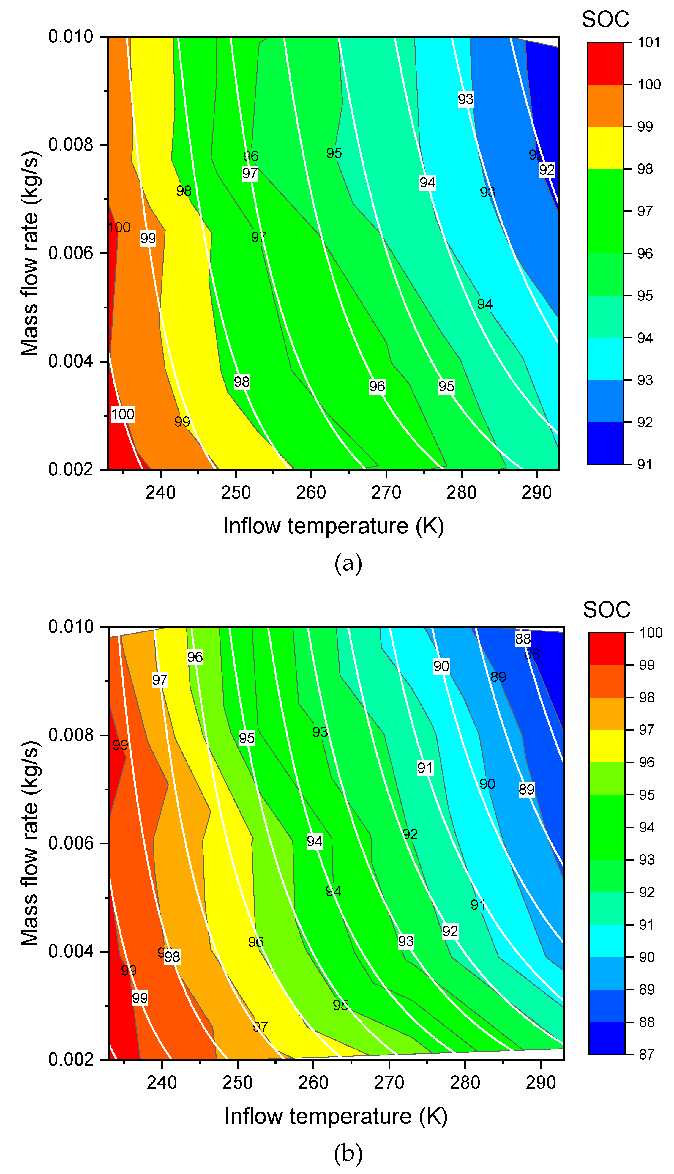
3.3. Effects of Inflow Temperature and Mass Flow Rate on SOC
As seen from
Section 3.1 and
Section 3.2, a deviation of the fitted parameters exists in the different cases. Herein, a new modified formula is proposed taking the effects of inflow temperature and mass flow rate simultaneously into consideration. According to [
3,
18], the heat transfer coefficient is proportional to the Nusselt number, while the Nusselt number is the exponential function of the Reynolds number, and the Reynolds number is proportional to the mass flow rate, thus the functional relationship between the heat transfer coefficient
and the mass flow rate
(unit kg/s is used here for expressing source data of fitting) can be modified as follows:
Combining Equation (15) with
, it is obtained that:
where
,
. We use this new definition of
in Equation (11), and thus the new analytical model can be written as follows:
Herein, we fix
. Now
,
and
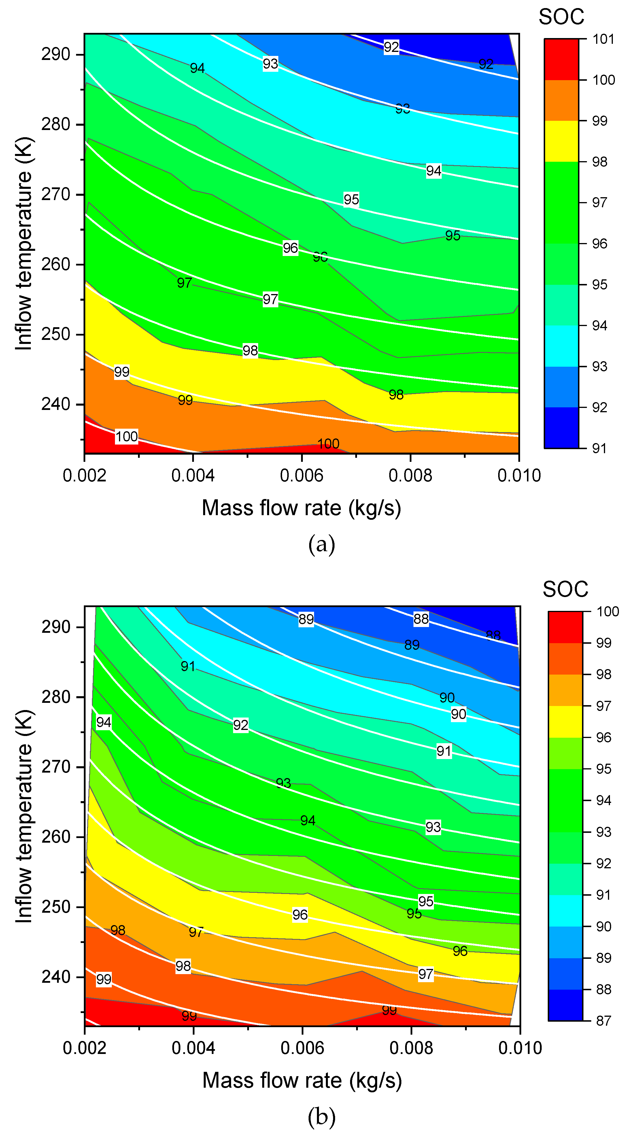
are the new fitted parameters. The new formula of Equation (17) can be used to do the three dimensional (3D) surface fitting for the Type III (
Figure 3a,
Figure 4a) and Type IV (
Figure 3b,
Figure 4b). As shown in these figures, the fit shows a good agreement. The values of the fitted parameters are shown in the
Table 3. Exchange of
X axis and
Y axis of the contour plotting (changed from
Figure 3 to
Figure 4) does not affect the values of the fitted parameters in
Table 3.
4. Conclusions
(1) SOC, defined as the ratio of the hydrogen density during refueling to the full-filling density, can be transformed to be the ratio of the hydrogen mass to the full-filling mass, and the full-filling mass can be calculated if the volume of the tank is given.
(2) The analytical solution of SOC can be obtained from a thermodynamic model. This model is a lumped parameter model, and mass balance equation and energy balance equation are applied. The deduced formula can be used to determine SOC from the refueling parameters.
(3) The effects of inflow temperature and mass flow rate on SOC are presented, both of them have a negative effect on SOC. To improve SOC, it is supposed to precool the hydrogen gas (decrease the inflow temperature) in advance and reduce the mass flow rate.
(4) The Type IV tank is more sensitive than Type III to the refueling parameters. When the refueling condition varies, the SOC of Type IV changes more than that of Type III.
(5) The thermodynamic model will be improved and extended to the dual zone (gas zone and wall zone) model, not only the behavior of the hydrogen gas is researched, but also the effect of the tank wall will be considered.


