Finite Control Set Model Predictive Control for Parallel Connected Online UPS System under Unbalanced and Nonlinear Loads

 ,
, 
Abstract
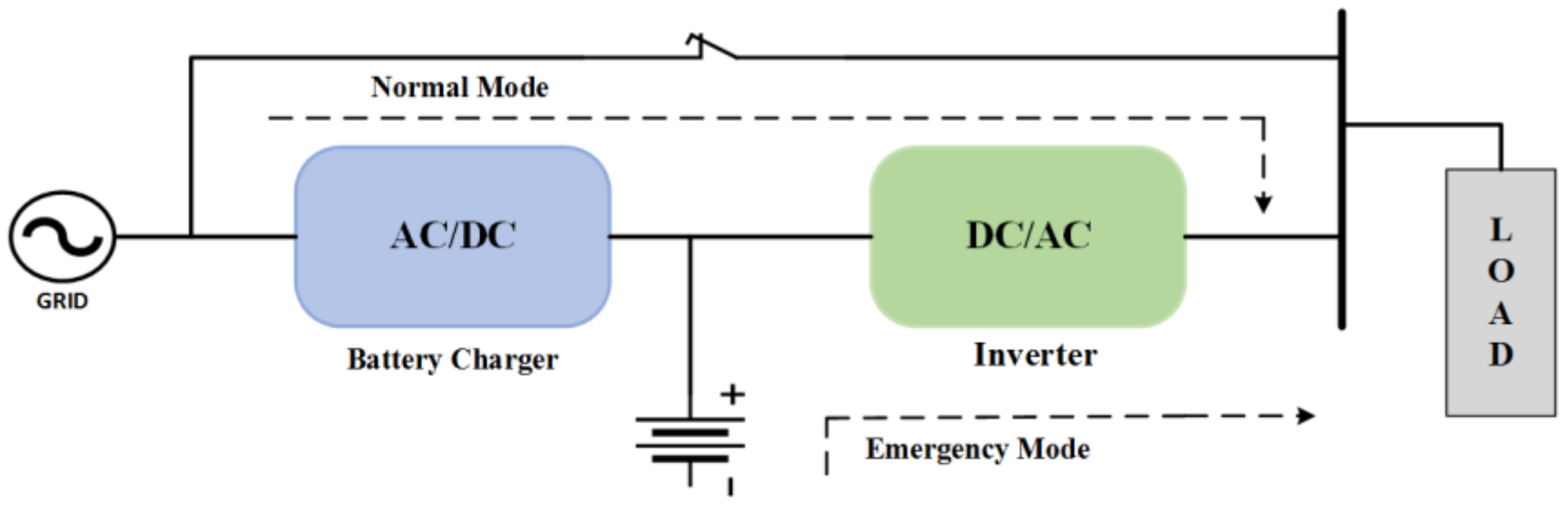
:1. Introduction
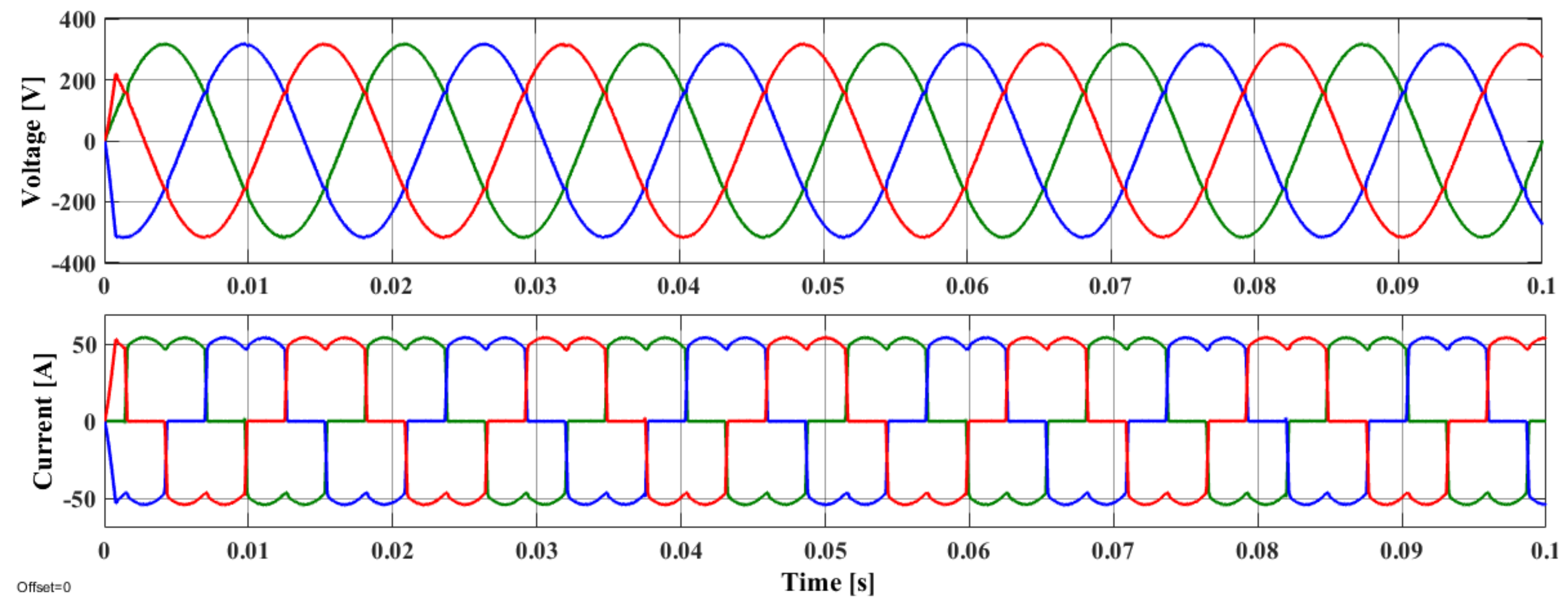
- THD of inverter’s output voltage is less than 4% under all loading conditions.
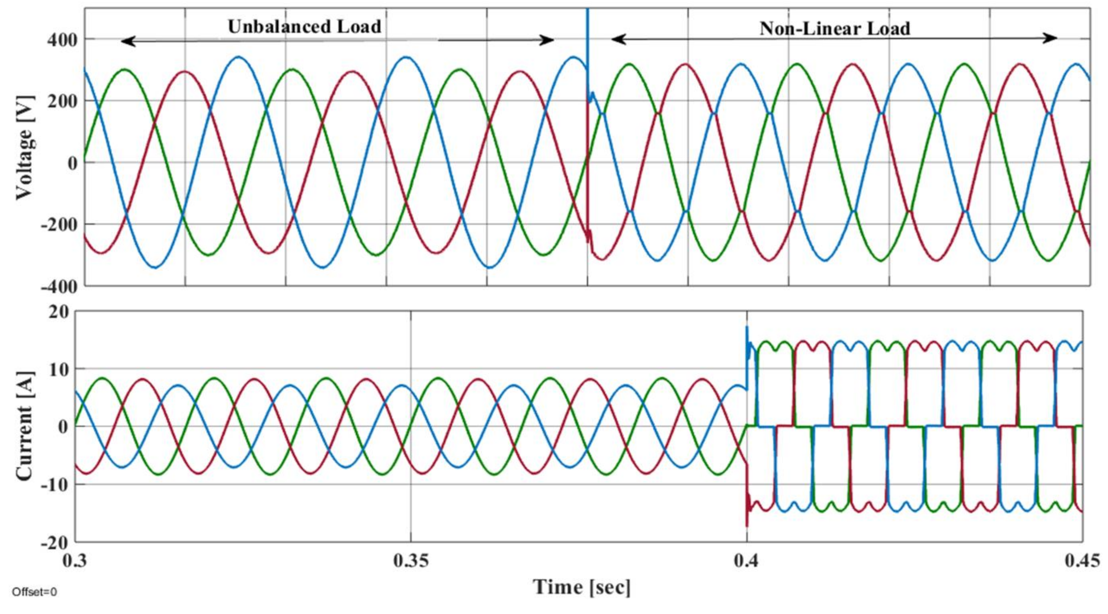
- Voltage drop is not more than 5% under all loading conditions.
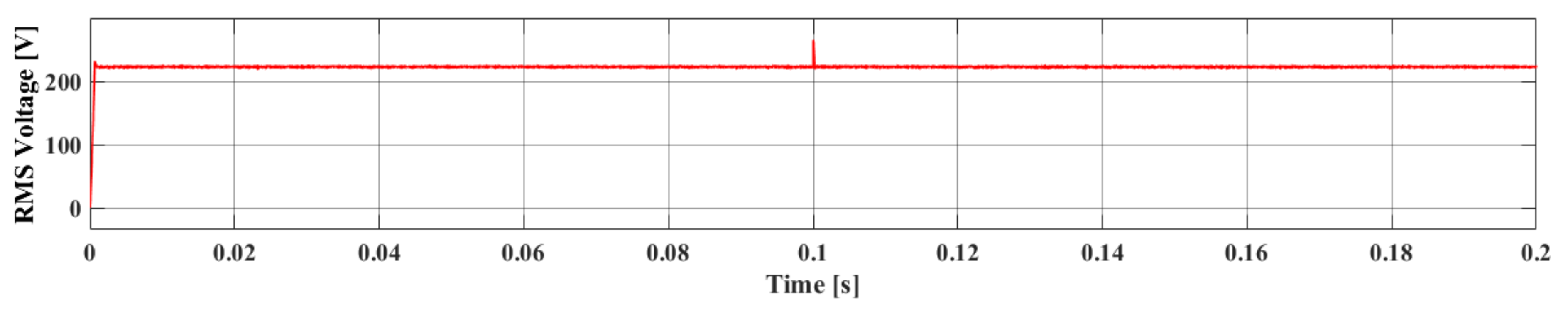
- The inverter provides constant output root mean square (RMS) voltage, irrespective to disturbance or variation in system parameters such as temperature, load current, etc. [1]
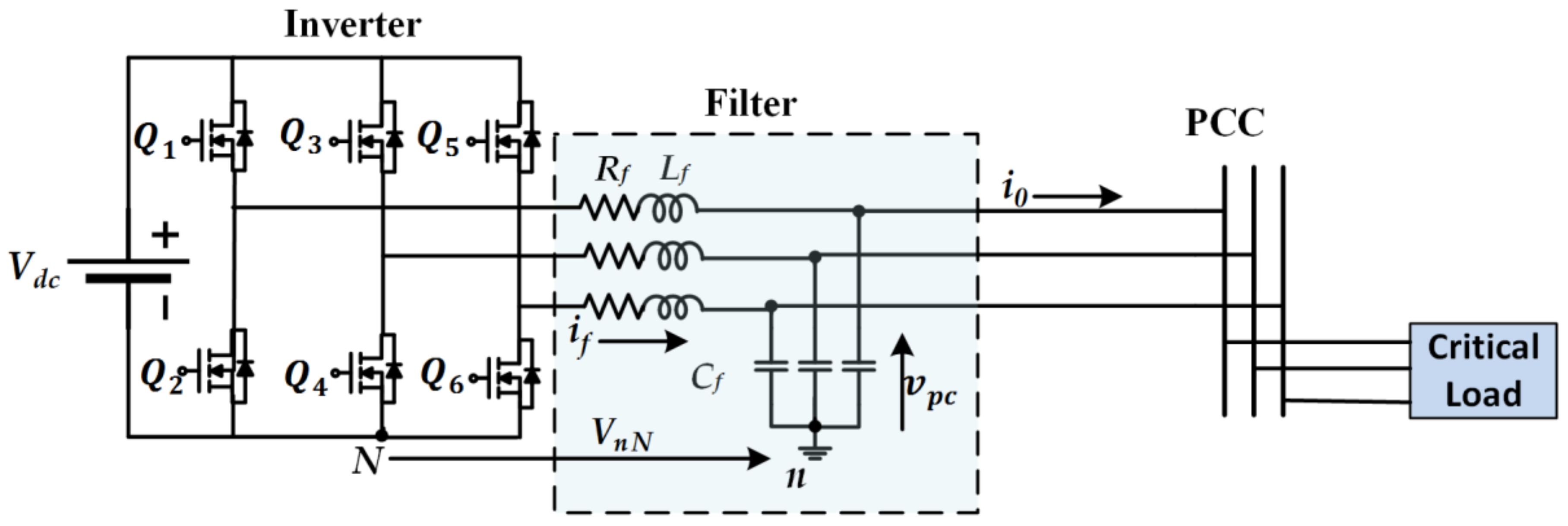
2. Description and Mathematical Modelling of System
2.1. LC Filter Modelling
2.2. Discrete Time Domain Modelling
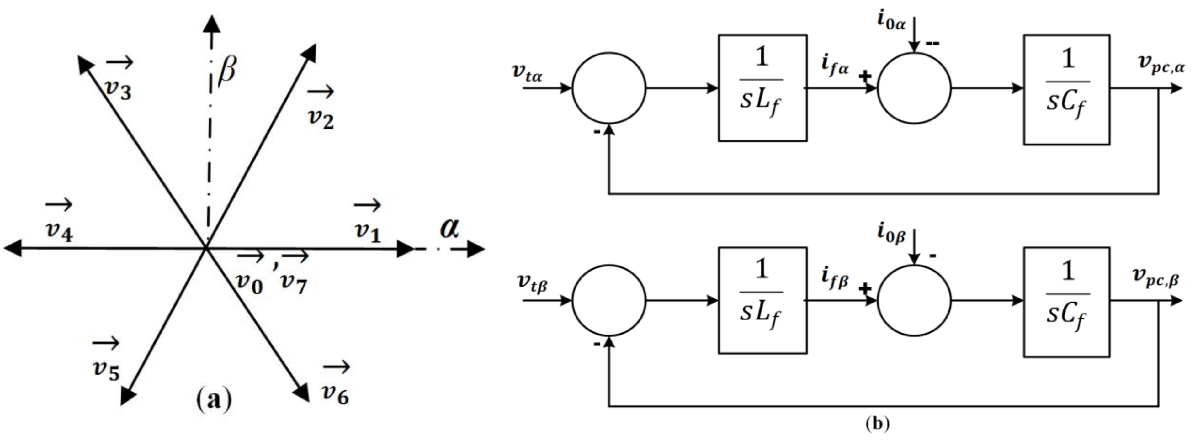
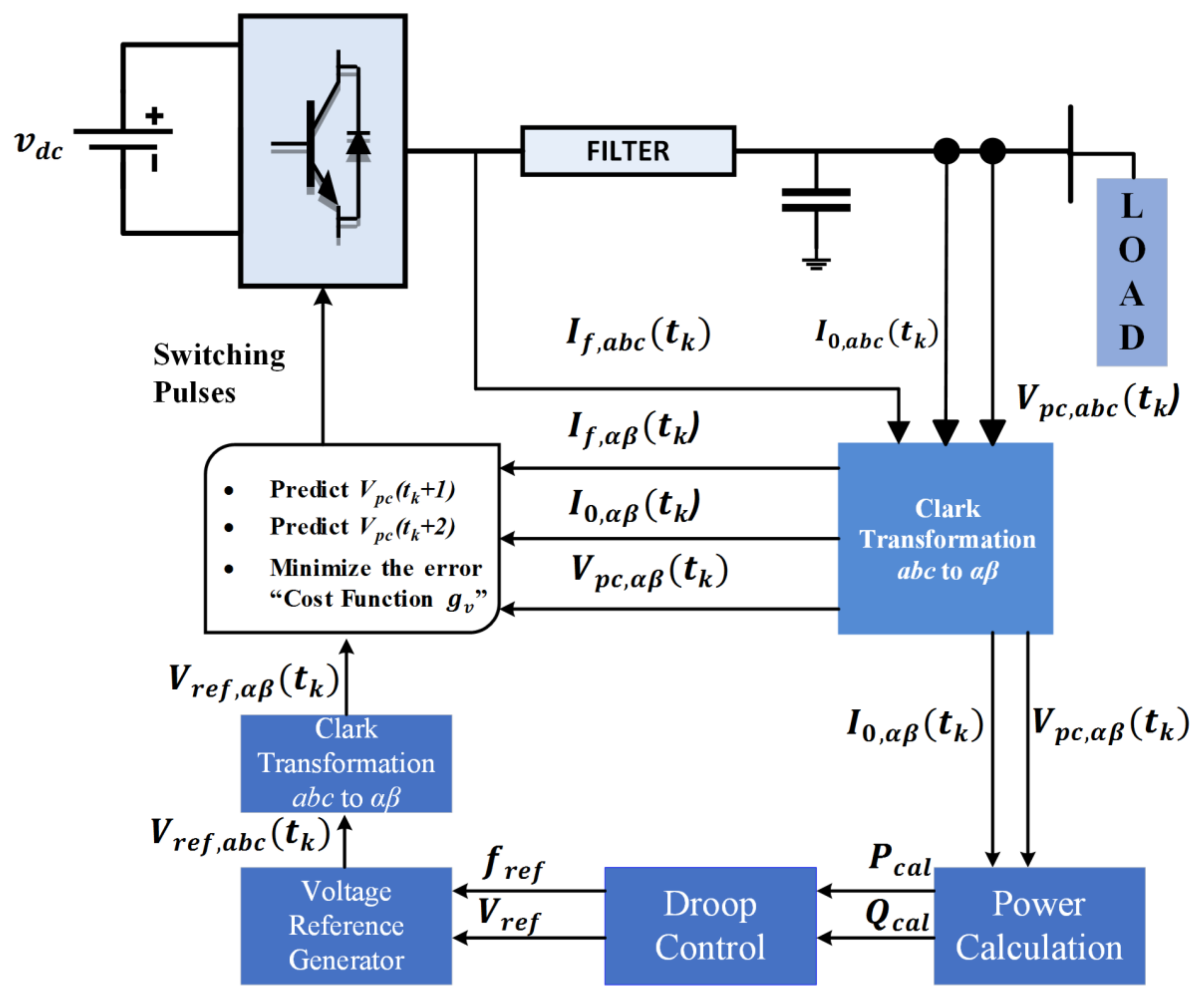
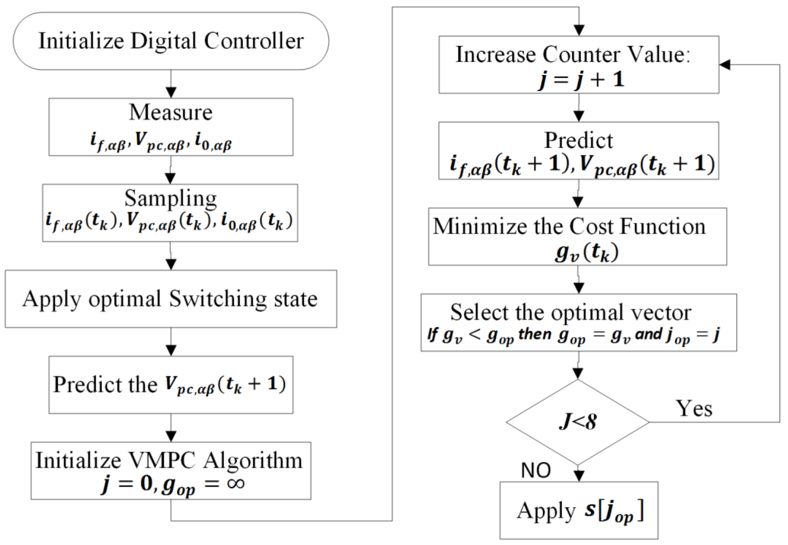
3. Operating Principle of FCS–MPC
- In the start of each sampling time, and are measured through sensors.
- The information is sent to the algorithm, it is defined by the initial point from where the algorithm forecasts the future behavior of controlled variables using Equation (14), for all possible voltage vectors.
- These predicted values are used to find the predefined cost functions (CF) and a voltage vector that has a minimal value of CF as applied to VSI.
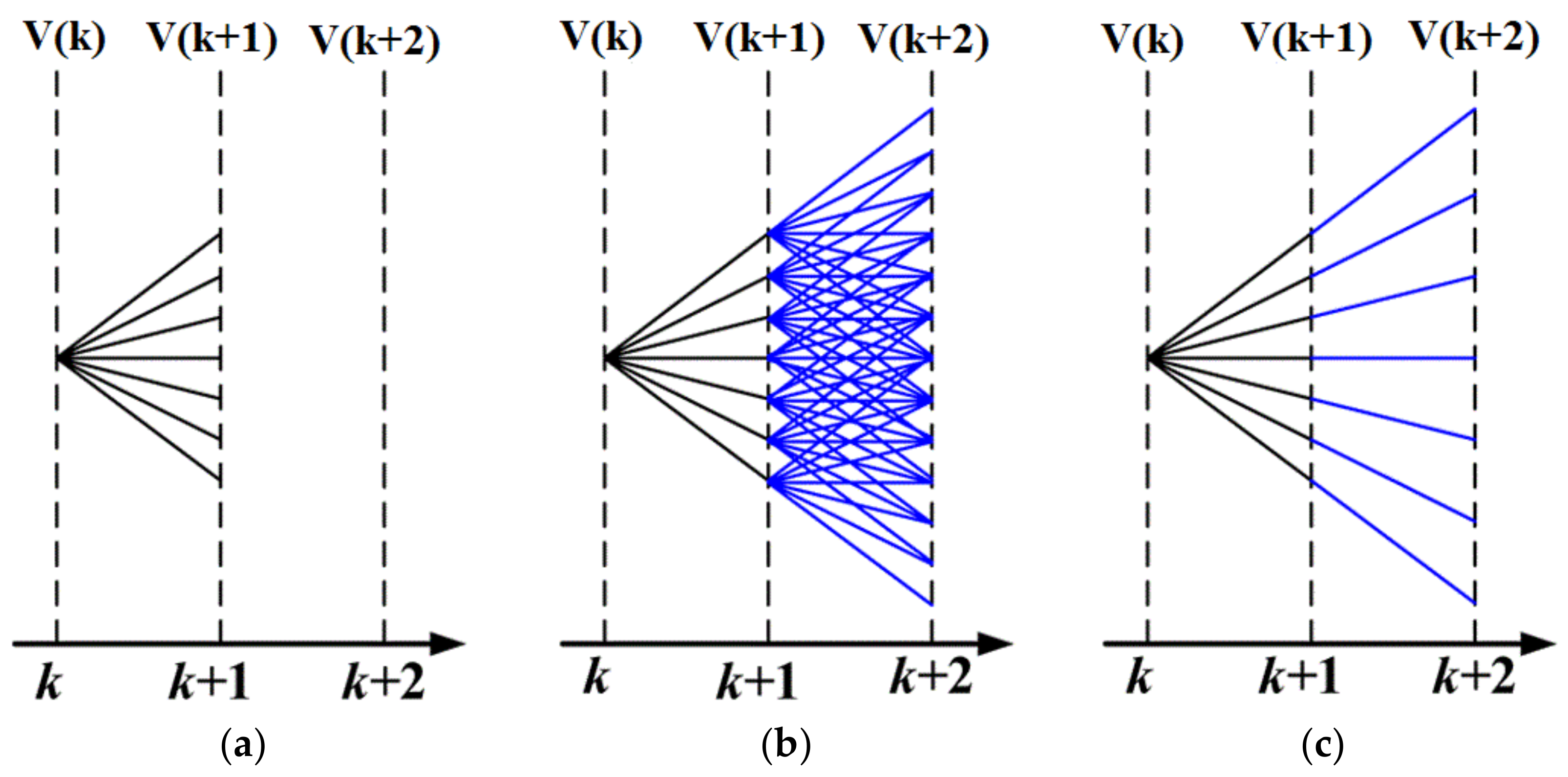
Switching Frequency Reduction Scheme
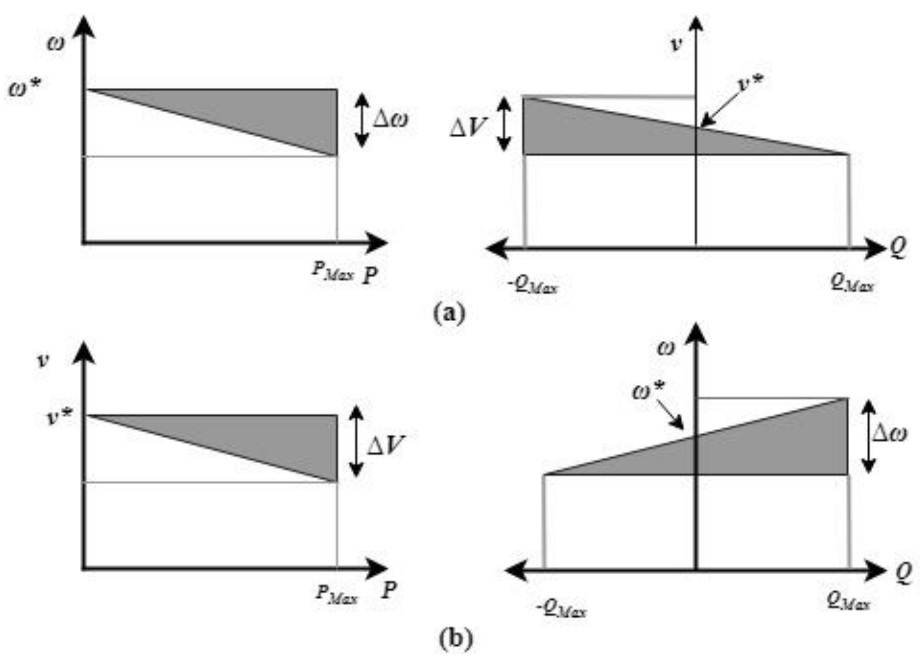
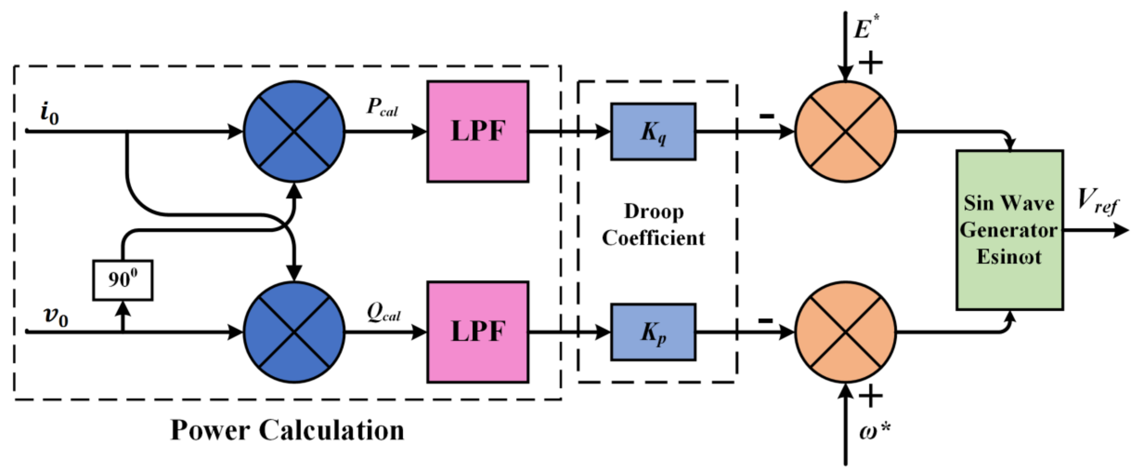
4. Droop Control
5. Results
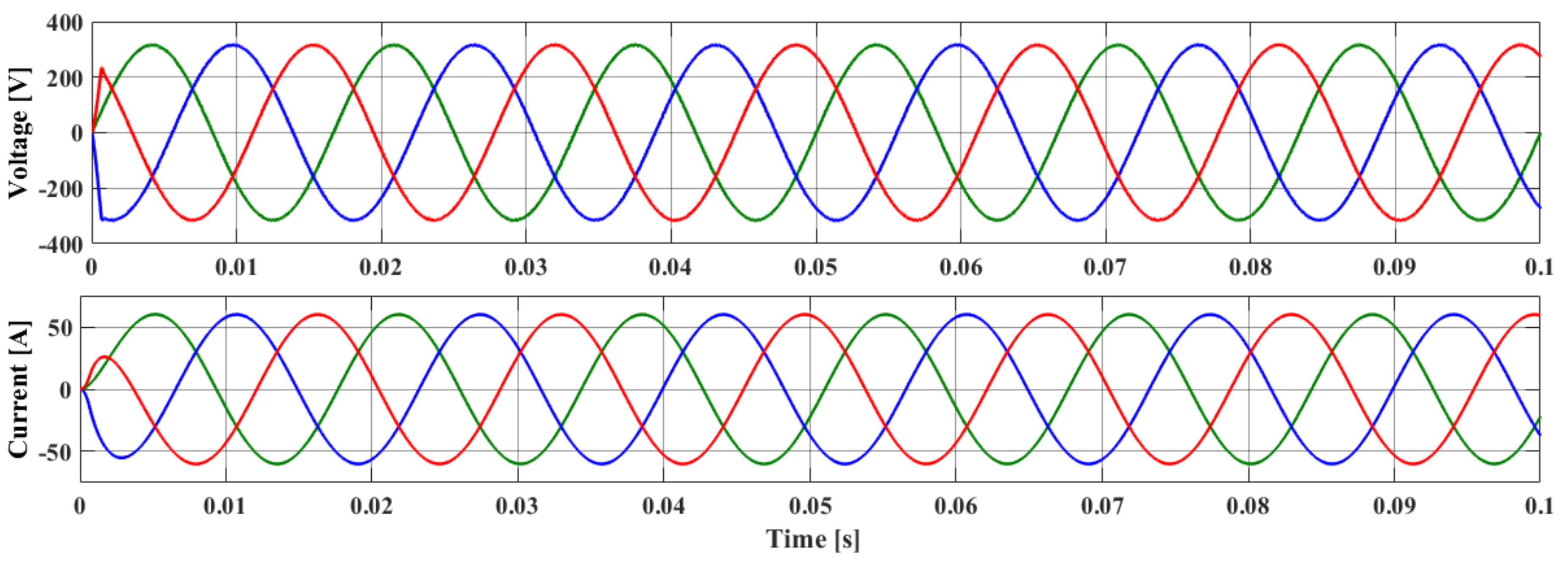
5.1. Steady State Analysis
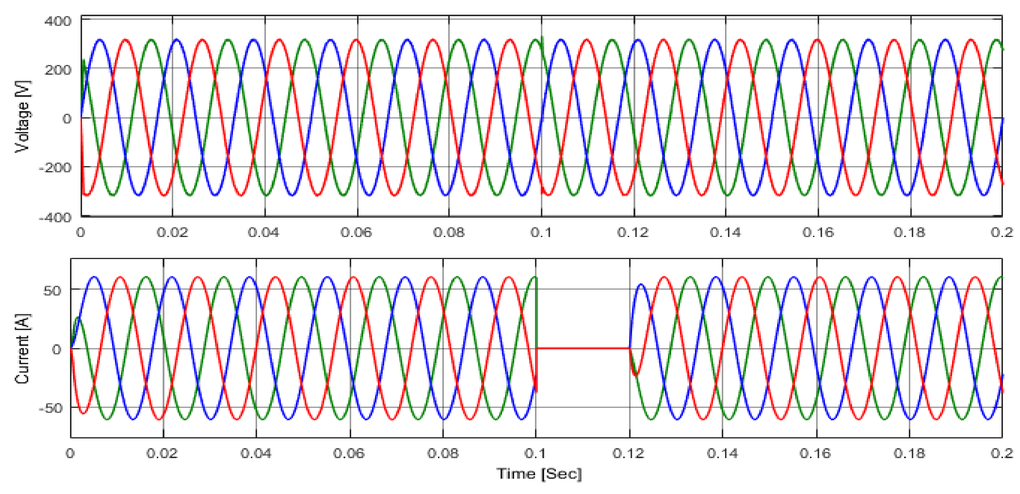
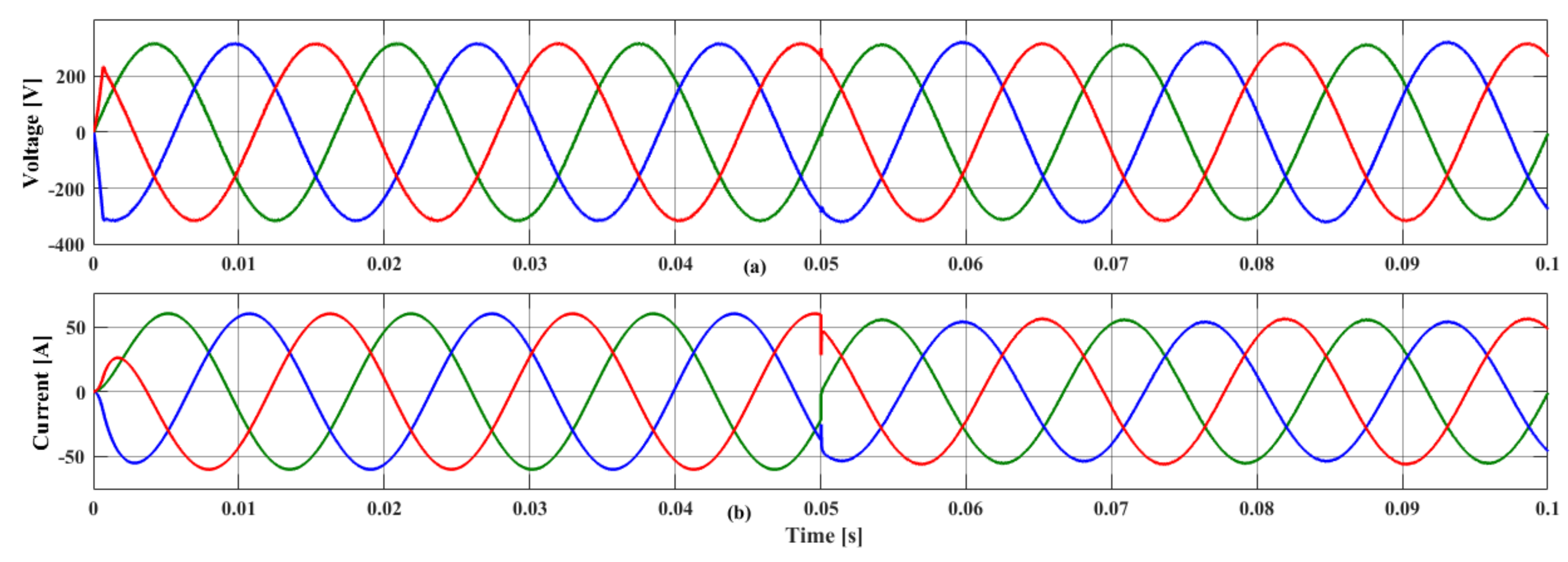
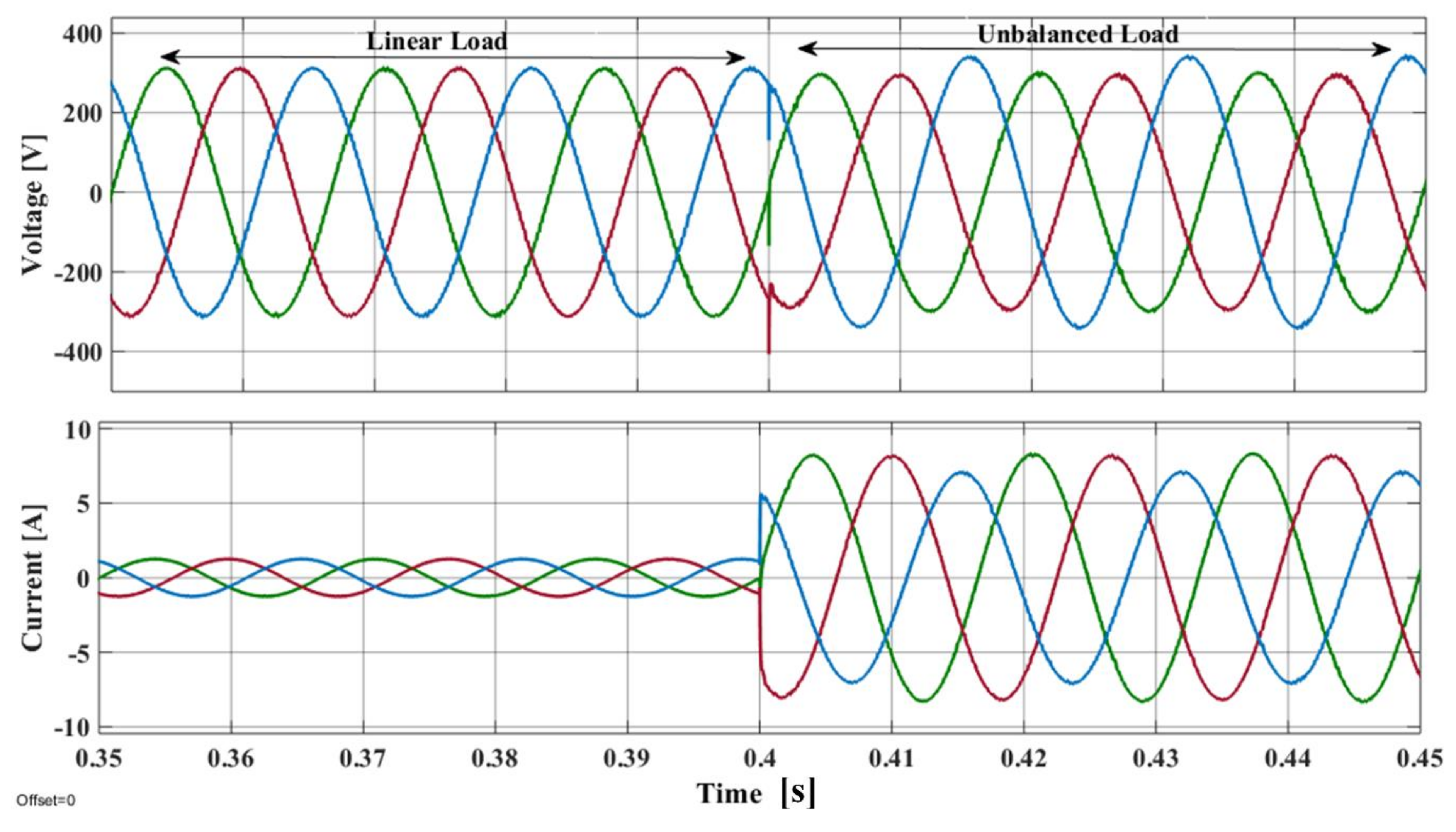
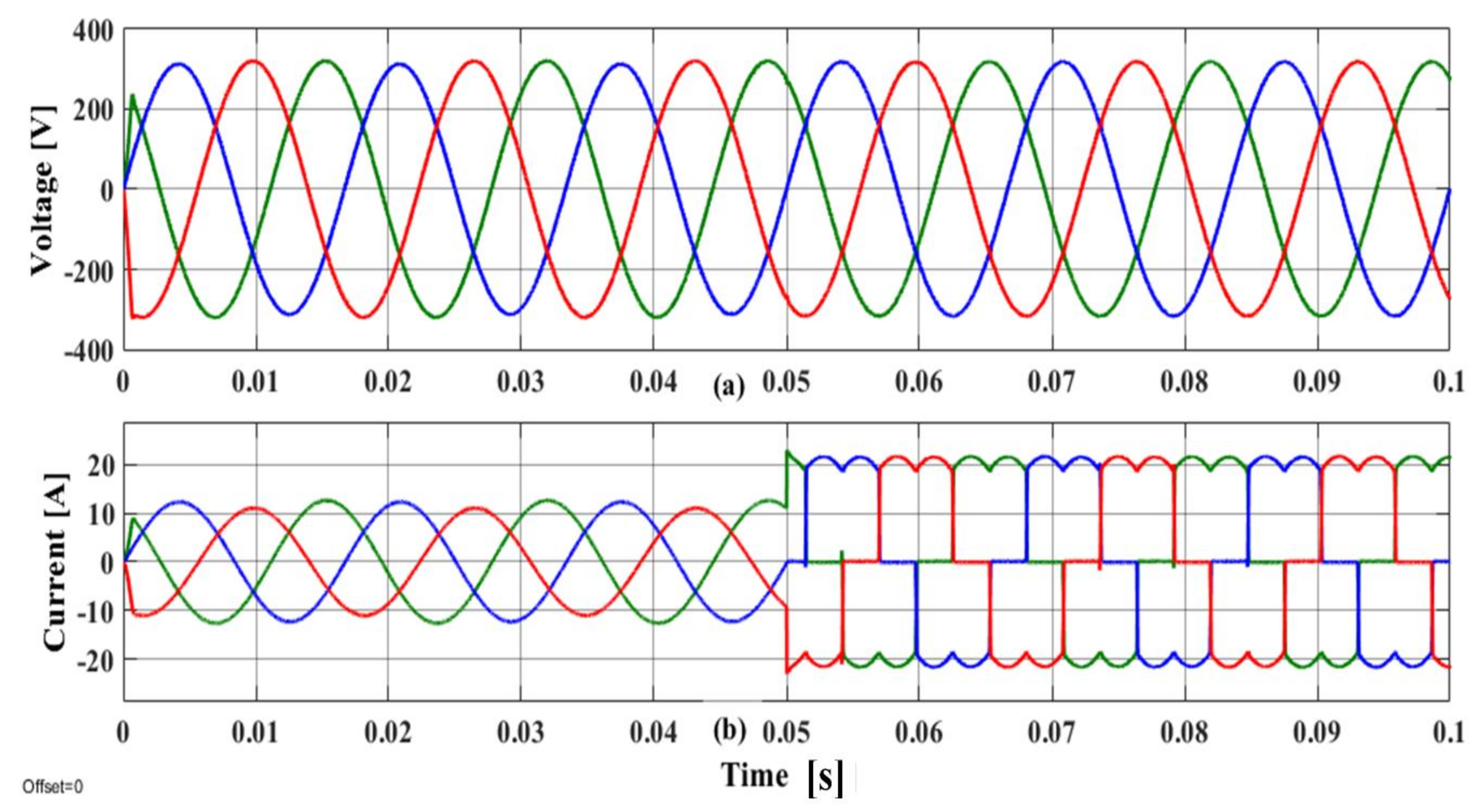
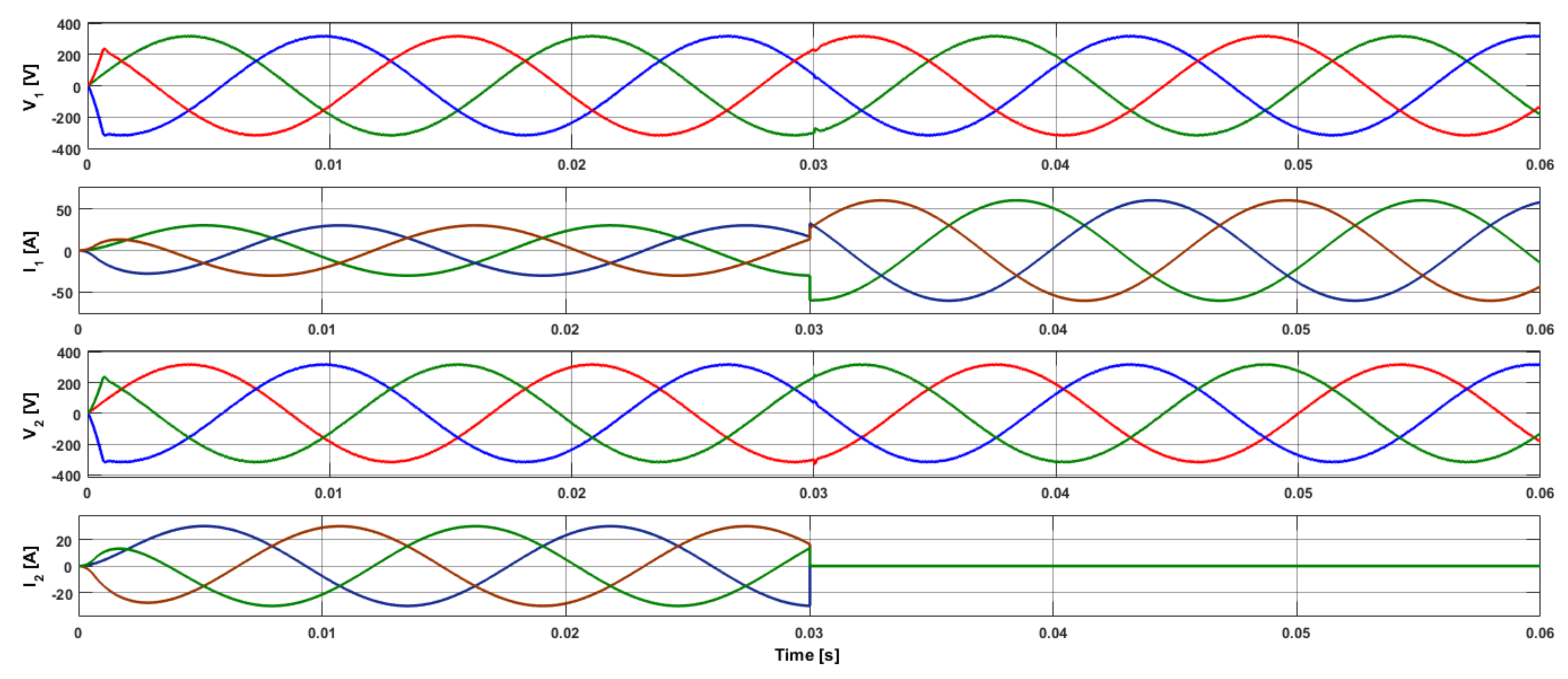
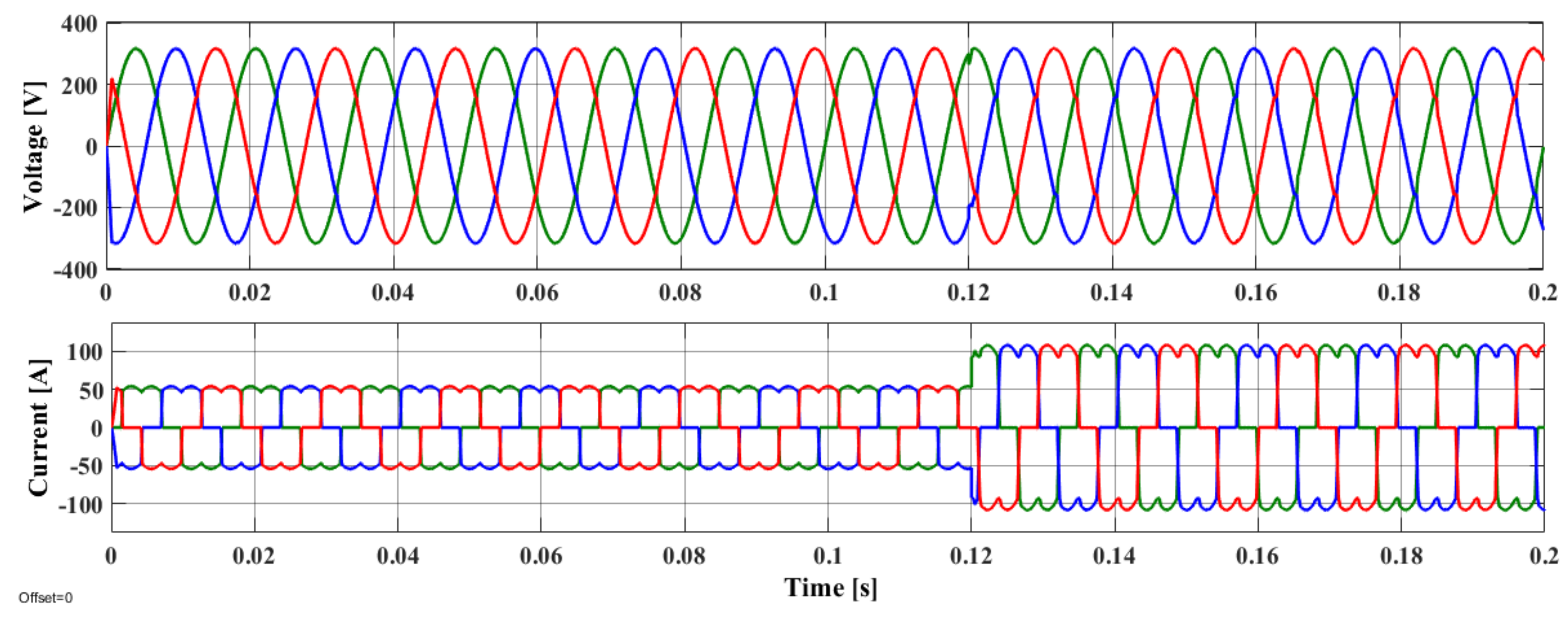
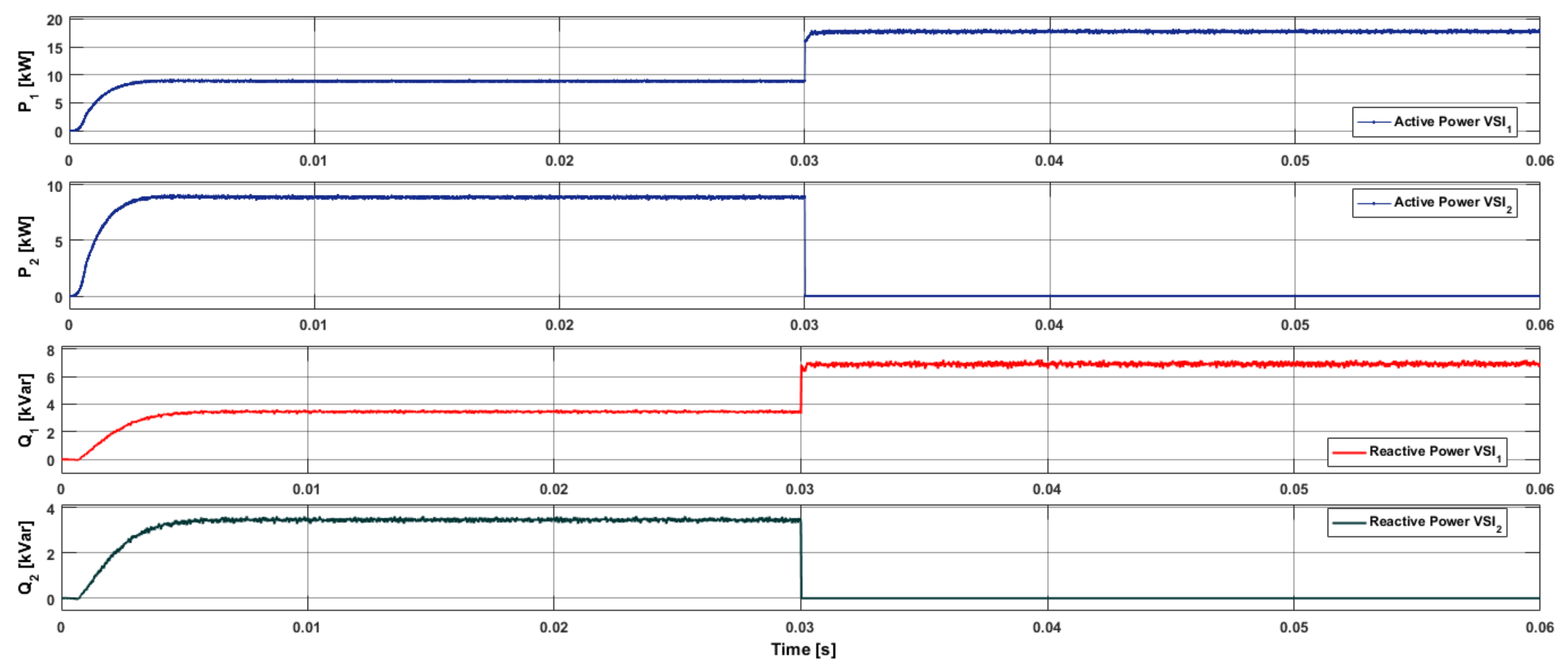
5.2. Load Transient Analysis
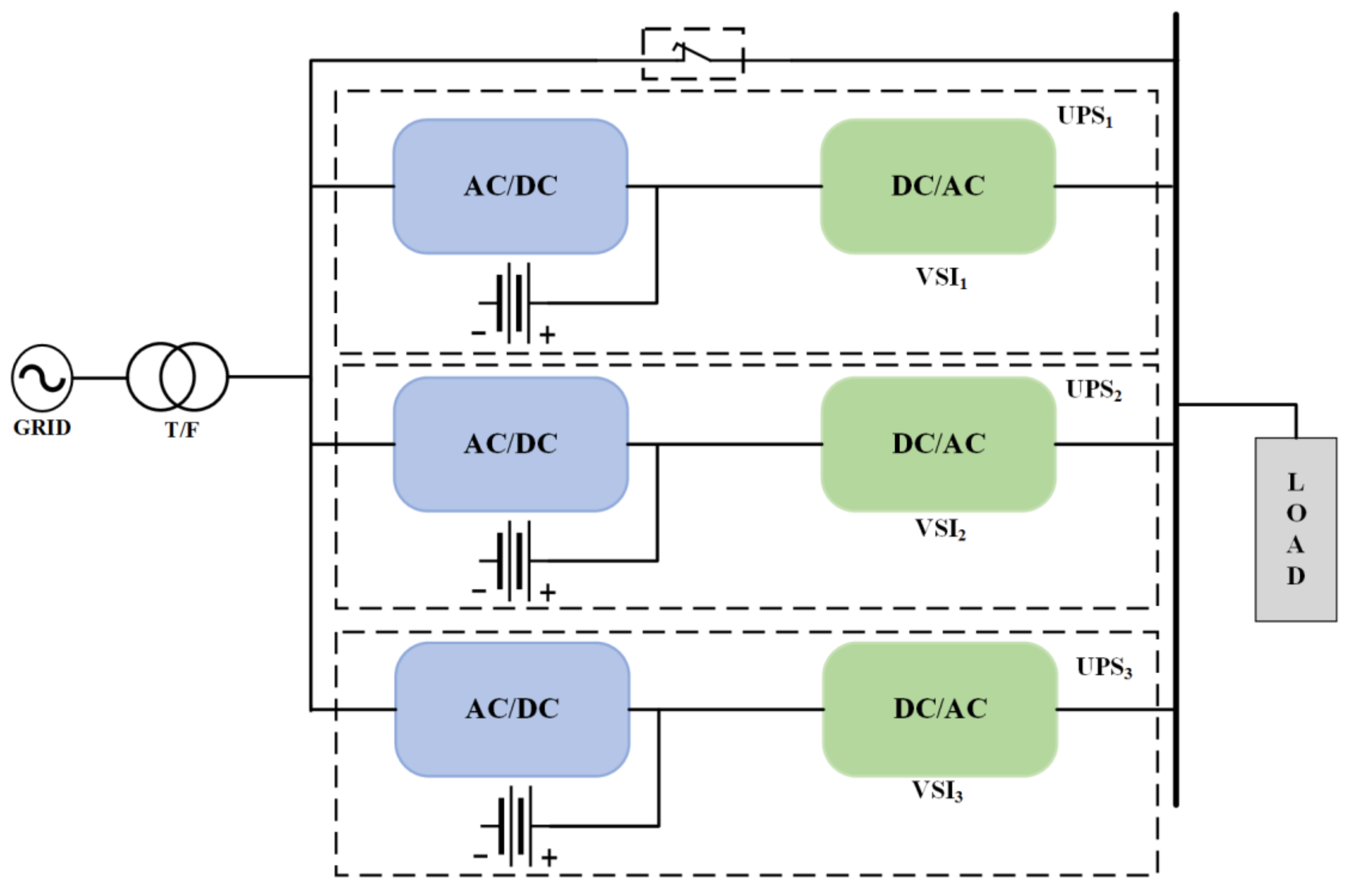
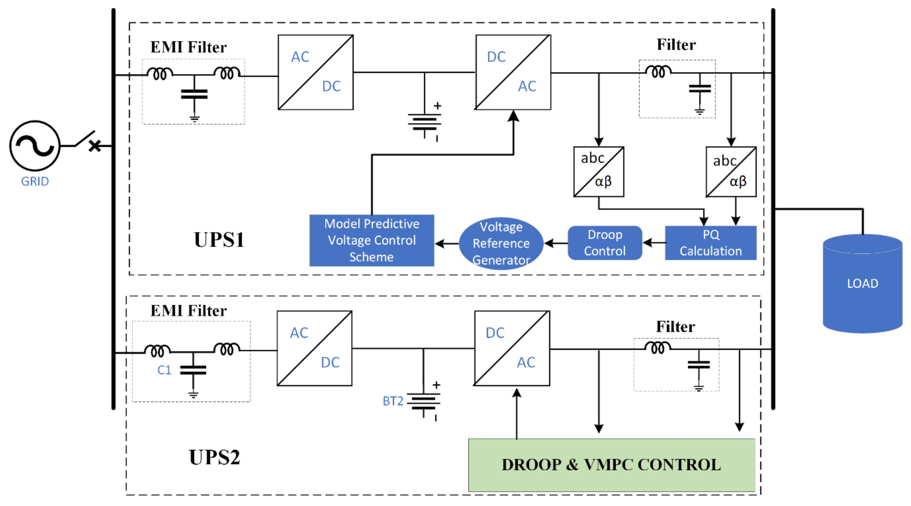
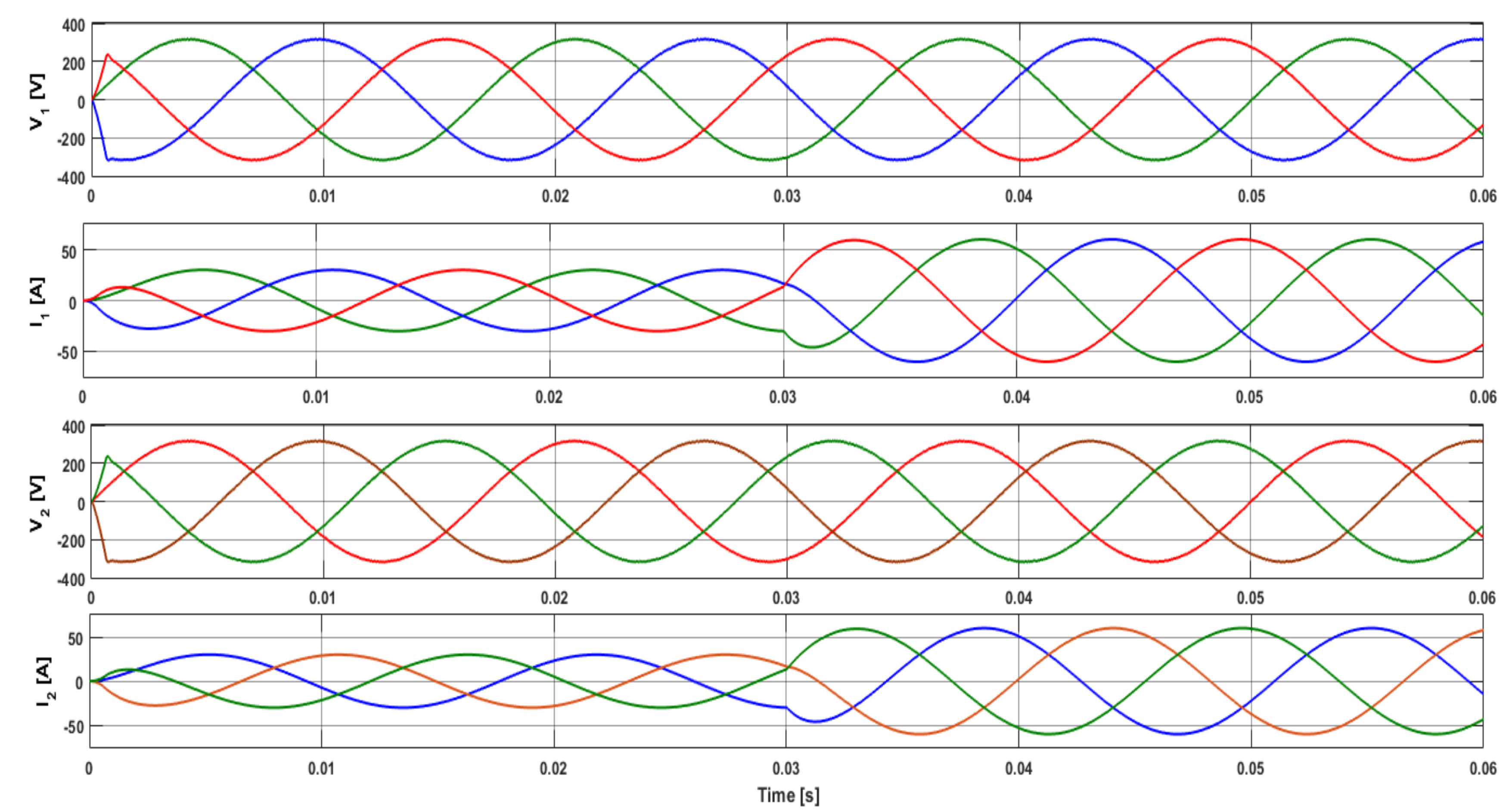
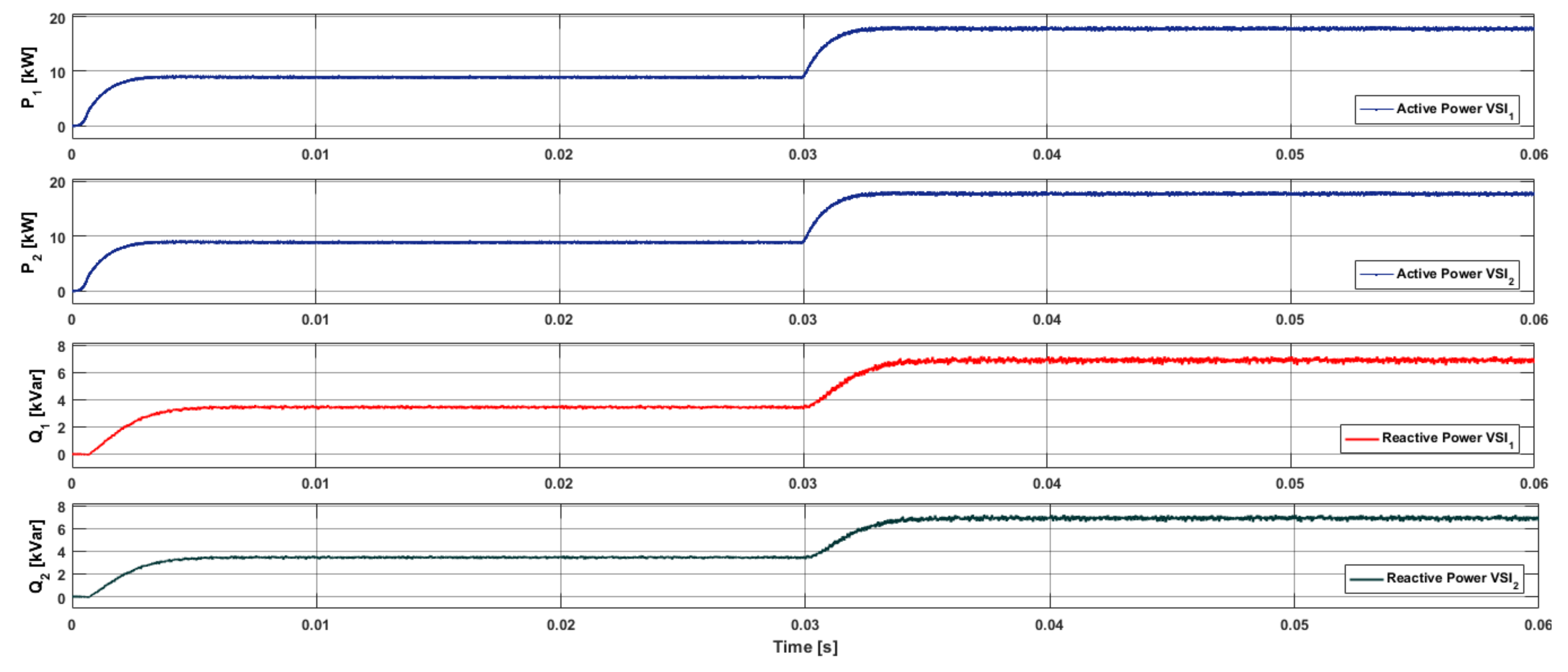
5.3. Multiple UPS Systems
6. Conclusions
Author Contributions
Funding
Conflicts of Interest
References
- Aamir, M.; Kalwar, K.A.; Mekhilef, S. Uninterruptible power supply (UPS) system. Renew. Sustain. Energy Rev. 2016, 58, 1395–1410. [Google Scholar] [CrossRef]
- Zhang, C.; Guerrero, J.M.; Vasquez, J.C.; Coelho, E.A.A. Control architecture for parallel-connected inverters in uninterruptible power systems. IEEE Trans. Power Electron. 2016, 31, 5176–5188. [Google Scholar]
- Guerrero, J.M.; Hang, L.; Uceda, J. Control of distributed uninterruptible power supply systems. IEEE Trans. Ind. Electron. 2008, 55, 2845–2859. [Google Scholar] [CrossRef]
- Cheng, Y.J.; Sng, E.K.K. A novel communication strategy for decentralized control of paralleled multi-inverter systems. IEEE Trans. Power Electron. 2006, 21, 148–156. [Google Scholar] [CrossRef]
- Sun, X.; Lee, Y.-S.; Xu, D. Modeling, analysis, and implementation of parallel multi-inverter systems with instantaneous average-current-sharing scheme. IEEE Trans. Power Electron. 2003, 18, 844–856. [Google Scholar]
- Tayab, U.B.; Roslan, M.A.B.; Hwai, L.J.; Kashif, M. A review of droop control techniques for microgrid. Renew. Sustain. Energy Rev. 2017, 76, 717–727. [Google Scholar] [CrossRef]
- Mattavelli, P. An improved deadbeat control for UPS using disturbance observers. IEEE Trans. Ind. Electron. 2005, 52, 206–212. [Google Scholar] [CrossRef]
- Kawabata, T.; Miyashita, T.; Yamamoto, Y. Dead beat control of three phase PWM inverter. IEEE Trans. Power Electron. 1990, 5, 21–28. [Google Scholar] [CrossRef]
- Yang, S.; Lei, Q.; Peng, F.Z.; Qian, Z. A robust control scheme for grid-connected voltage-source inverters. IEEE Trans. Ind. Electron. 2011, 58, 202–212. [Google Scholar] [CrossRef]
- Willmann, G.; Coutinho, D.F.; Pereira, L.F.A.; Líbano, F.B. Multiple-loop H-infinity control design for uninterruptible power supplies. IEEE Trans. Ind. Electron. 2007, 54, 1591–1602. [Google Scholar] [CrossRef]
- Komurcugil, H. Rotating-sliding-line-based sliding-mode control for single-phase UPS inverters. IEEE Trans. Ind. Electron. 2012, 59, 3719–3726. [Google Scholar] [CrossRef]
- Marwali, M.N.; Dai, M.; Keyhani, A. Robust stability analysis of voltage and current control for distributed generation systems. IEEE Trans. Energy Convers. 2006, 21, 516–526. [Google Scholar] [CrossRef]
- Kim, D.-E.; Lee, D.-C. Feedback linearization control of three-phase UPS inverter systems. IEEE Trans. Ind. Electron. 2010, 57, 963–968. [Google Scholar]
- Lu, B.; Jan, L.; Jan, Y.-N. Control of Cell Divisions in the Nervous System: Symmetry and Asymmetry. Annu. Rev. Neurosci. 2000, 23, 531–556. [Google Scholar] [CrossRef] [PubMed]
- Precup, R.-E.; Preitl, S.; Korondi, P. Fuzzy controllers with maximum sensitivity for servosystems. IEEE Trans. Ind. Electron. 2007, 54, 1298–1310. [Google Scholar] [CrossRef]
- Vrkalovic, S.; Teban, T.-A.; Borlea, I.-D. Stable Takagi-Sugeno fuzzy control designed by optimization. Int. J. Artif. Intell. 2017, 15, 17–29. [Google Scholar]
- Kukrer, O.; Komurcugil, H.; Doganalp, A. A three-level hysteresis function approach to the sliding-mode control of single-phase UPS inverters. IEEE Trans. Ind. Electron. 2009, 56, 3477–3486. [Google Scholar] [CrossRef]
- Kang, H.-K.; Yoo, C.H.; Chung, I.Y.; Won, D.J.; Moon, S.I. Intelligent coordination method of multiple distributed resources for harmonic current compensation in a microgrid. J. Electr. Eng Technol. 2012, 7, 834–844. [Google Scholar] [CrossRef]
- Jiang, S.; Cao, D.; Li, Y.; Liu, J.; Peng, F.Z. Low-THD, fast-transient, and cost-effective synchronous-frame repetitive controller for three-phase UPS inverters. IEEE Trans. Power Electron. 2012, 27, 2994–3005. [Google Scholar] [CrossRef]
- Lu, W.; Zhou, K.; Wang, D.; Cheng, M. A general parallel structure repetitive control scheme for multiphase DC–AC PWM converters. IEEE Trans. Power Electron. 2013, 28, 3980–3987. [Google Scholar] [CrossRef]
- Cortes, P.; Wilson, A.; Kouro, S.; Rodriguez, J.; Abu-Rub, H. Model predictive control of multilevel cascaded H-bridge inverters. IEEE Trans. Ind. Electron. 2010, 57, 2691–2699. [Google Scholar] [CrossRef]
- Yaramasu, V.; Wu, B. Predictive control of a three-level boost converter and an NPC inverter for high-power PMSG-based medium voltage wind energy conversion systems. IEEE Trans. Power Electron. 2014, 29, 5308–5322. [Google Scholar] [CrossRef]
- Kwak, S.; Park, J.-C. Model-predictive direct power control with vector preselection technique for highly efficient active rectifiers. IEEE Trans. Ind. Inform. 2015, 11, 44–52. [Google Scholar] [CrossRef]
- Cortés, P.; Rodríguez, J.; Quevedo, D.E.; Silva, C. Predictive current control strategy with imposed load current spectrum. IEEE Trans. Power Electron. 2008, 23, 612–618. [Google Scholar] [CrossRef]
- Nguyen, T.-T.; Yoo, H.-J.; Kim, H.-M. Application of model predictive control to BESS for microgrid control. Energies 2015, 8, 8798–8813. [Google Scholar] [CrossRef]
- Arahal, M.R.; Barrero, F.; Durán, M.J.; Ortega, M.G.; Martín, C. Trade-offs analysis in predictive current control of multi-phase induction machines. Control Eng. Pract. 2018, 81, 105–113. [Google Scholar] [CrossRef]
- Lim, C.S.; Levi, E.; Jones, M.; Rahim, N.A.; Hew, W.P. FCS-MPC-based current control of a five-phase induction motor and its comparison with PI-PWM control. IEEE Trans. Ind. Electron. 2014, 61, 149–163. [Google Scholar] [CrossRef]
- Arahal, M.R.; Barrero, F.; Ortega, M.G.; Martin, C. Harmonic analysis of direct digital control of voltage inverters. Math. Comput. Simul. 2016, 130, 155–166. [Google Scholar] [CrossRef]
- Yaramasu, V.; Rivera, M.; Narimani, M.; Wu, B.; Rodriguez, J. Model predictive approach for a simple and effective load voltage control of four-leg inverter with an output LC filter. IEEE Trans. Ind. Electron. 2014, 61, 5259–5270. [Google Scholar] [CrossRef]
- Cortés, P.; Ortiz, G.; Yuz, J.I.; Rodríguez, J.; Vazquez, S.; Franquelo, L.G. Model predictive control of an inverter with output $ LC $ filter for UPS applications. IEEE Trans. Ind. Electron. 2009, 56, 1875–1883. [Google Scholar] [CrossRef]
- Nauman, M.; Hasan, A. Efficient implicit model-predictive control of a three-phase inverter with an output LC filter. IEEE Trans. Power Electron. 2016, 31, 6075–6078. [Google Scholar] [CrossRef]
- Vazquez, S.; Leon, J.I.; Franquelo, L.G.; Carrasco, J.M.; Dominguez, E.; Cortes, P.; Rodriguez, J. Comparison Between FS-MPC Control Strategy for an UPS inverter application in α-β and abc frames. In Proceedings of the 2010 IEEE International Symposium on Industrial Electronics (ISIE), Bari, Italy, 4–7 July 2010. [Google Scholar]
- Hu, J.; Zhu, J.; Dorrell, D.G. Model predictive control of grid-connected inverters for PV systems with flexible power regulation and switching frequency reduction. IEEE Trans. Ind. Appl. 2015, 51, 587–594. [Google Scholar] [CrossRef]
- Zhong, Q.-C. Robust droop controller for accurate proportional load sharing among inverters operated in parallel. IEEE Trans. Ind. Electron. 2013, 60, 1281–1290. [Google Scholar] [CrossRef]
- Leon, J.I.; Kouro, S.; Franquelo, L.G.; Rodriguez, J.; Wu, B. The essential role and the continuous evolution of modulation techniques for voltage-source inverters in the past, present, and future power electronics. IEEE Trans. Ind. Electron. 2016, 63, 2688–2701. [Google Scholar] [CrossRef]
- Loh, P.C.; Newman, M.J.; Zmood, D.N.; Holmes, D.G. A comparative analysis of multiloop voltage regulation strategies for single and three-phase UPS systems. IEEE Trans. Power Electron. 2003, 18, 1176–1185. [Google Scholar]
- Hasanzadeh, A.; Onar, O.C.; Mokhtari, H.; Khaligh, A. A proportional-resonant controller-based wireless control strategy with a reduced number of sensors for parallel-operated UPSs. IEEE Trans. Power Deliv. 2010, 25, 468–478. [Google Scholar] [CrossRef]


| Space Vector | Switching Vector | On-State Switch | Vector Placing | |
|---|---|---|---|---|
| Zero vector | ||||
| Active vector | ||||
| Output Impedance | ||
|---|---|---|
| Active Power | ||
| Reactive Power | ||
| Frequency Droop | ||
| Amplitude Droop | ||
| Droop coefficient | ||
| Droop coefficient |
| Parameter | Value |
|---|---|
| DC link Voltage | |
| Sampling Time | |
| LC-filter | |
| Damping Resistance | |
| Linear load | |
| Non-linear load (diode rectifier) | |
| Nominal Voltage | |
| Average Switching Frequency | |
| Rated Frequency | |
| Droop coefficients | |
| Proportional Gain | kp = 50 |
| Proportional Integrator |
| Load Types | Proposed MPC Voltage THD (%) | PI Voltage THD (%) |
|---|---|---|
| Balanced resistive load | 0.96 | 1.22 |
| No Load | 0.96 | 1.22 |
| Non-Linear Load | 1.23 | 4.31 |
| Reference | Control Technique | %Voltage THD Linear Load | %Voltage THD Non-Linear Load | Controller Complexity |
|---|---|---|---|---|
| [36] | PI | 16 | 42 | Low |
| [7] | Dead Beat | 2.1 | 4.8 | Medium |
| [37] | PR | 1.4 | 4.6 | Low |
| [11] | SMC | - | 2.66 | High |
| [29] | MPC | 5.1 | 6.7 | High |
| [30] | MPC (observer based) | 2.82 | 3.8 | Medium |
| [31] | Implicit-MPC | 2.93 | Not studied | Medium |
| Proposed | FCS–MPC | 0.96 | 1.23 | Medium |
© 2019 by the authors. Licensee MDPI, Basel, Switzerland. This article is an open access article distributed under the terms and conditions of the Creative Commons Attribution (CC BY) license (http://creativecommons.org/licenses/by/4.0/).
Share and Cite
Khan, H.S.; Aamir, M.; Ali, M.; Waqar, A.; Ali, S.U.; Imtiaz, J. Finite Control Set Model Predictive Control for Parallel Connected Online UPS System under Unbalanced and Nonlinear Loads. Energies 2019, 12, 581. https://doi.org/10.3390/en12040581
Khan HS, Aamir M, Ali M, Waqar A, Ali SU, Imtiaz J. Finite Control Set Model Predictive Control for Parallel Connected Online UPS System under Unbalanced and Nonlinear Loads. Energies. 2019; 12(4):581. https://doi.org/10.3390/en12040581
Chicago/Turabian StyleKhan, Hussain Sarwar, Muhammad Aamir, Muhammad Ali, Asad Waqar, Syed Umaid Ali, and Junaid Imtiaz. 2019. "Finite Control Set Model Predictive Control for Parallel Connected Online UPS System under Unbalanced and Nonlinear Loads" Energies 12, no. 4: 581. https://doi.org/10.3390/en12040581
APA StyleKhan, H. S., Aamir, M., Ali, M., Waqar, A., Ali, S. U., & Imtiaz, J. (2019). Finite Control Set Model Predictive Control for Parallel Connected Online UPS System under Unbalanced and Nonlinear Loads. Energies, 12(4), 581. https://doi.org/10.3390/en12040581