Abstract
Flow field plays an important role in the performance of proton exchange membrane (PEM) fuel cells, such as transporting reactants and removing water products. Therefore, the performance of a PEM fuel cell can be improved by optimizing the flow field dimensions and designs. In this work, single serpentine flow fields with four different land widths are used in PEM fuel cells to study the effects of the land width. The gas diffusion layers are made of carbon cloth. Since different land widths may be most suitable for different reactant flow rates, three different inlet flow rates are studied for all the flow fields with four different land widths. The effects of land width and inlet flow rate on fuel cell performance are studied based on the polarization curves and power densities. Without considering the pumping power, the cell performance always increases with the decrease in the land width and the increase in the inlet flow rates. However, when taking into consideration the pumping power, the net power density reaches the maximum at different combinations of land widths and reactant flow rates at different cell potentials.
1. Introduction
Proton exchange membrane (PEM) fuel cells are one of the promising renewable energy devices, owing to its high energy efficiency, low operating temperature, zero emission, and low noise. However, there are still some barriers that inhibit the widespread application of PEM fuel cells, such as high cost, low power density, and low durability [1,2]. Wilberforce et al. [3] reviewed the development of fuel cell electric cars and Zhang et al. [4,5] reviewed the degradation mechanisms in PEM fuel cell, and they found that the cost reduction, performance, and durability should be improved for the commercialization of the fuel cell. Flow field plays an important role in the performance and durability of PEM fuel cells since it helps to transport the reactants to the catalyst layer and reduces the liquid water accumulation in the catalyst layer [6,7]. Jung et al. [8] found that hydrogen crossover was strongly affected by the flow field dimension of the anode side. Oluwatosin et al. [9] reviewed different types of materials for flow field, and they found that a suitable coating on the flow field plate improved the corrosion resistance and fuel cell performance. There are three most commonly used flow fields: Serpentine, parallel, and interdigitated flow fields. The serpentine flow field is the most commonly used, since it has a better mass transfer than parallel flow field and a lower pumping power than interdigitated flow field [10].
Although the under-land cross-flow induced by the pressure difference between two adjacent channels in serpentine flow field helps to remove the excess produced liquid water and enhances the mass transfer, the concentration loss can still be high and can affect the fuel cell performance significantly. Many researchers have studied the channel designs from their numerical models [11]. Owejan et al. [12] found that the mass transfer loss can be decreased when the channel cross-section is changed from a rectangular shape to a triangular shape. Wang et al. [13] found that when the channel aspect ratio (channel height/width) decreased, the performance under both medium and low operating potential increased due to the increase of the under-land cross-flow rate, but the pumping power was increased as well. In addition, they found that the single serpentine flow field had a higher under-land cross-flow rate than multi-pass serpentine flow field. However, Nam et al. [14] found that the multi-pass serpentine flow-field had a higher under-land cross-flow rate than the single serpentine flow field instead, and the uniformity of local conditions and the fuel cell performance were improved with the multi-pass serpentine flow field. Shimpalee et al. [15] found that the 26-channel serpentine flow field gave the best performance and the lowest pumping power. Suresh et al. [16] introduced a split serpentine flow field with enhanced under-land cross-flow, and it improved the fuel cell performance significantly. Zheng et al. [17] added baffles in the downstream of the channel to improve the oxygen concentration and water removal ability, thus the performance under high current density region was increased.
Flow rate plays a significant role in fuel cell performance. Hu et al. [18] found that the flow rate had a large effect on the reactant concentration distribution in fuel cell. Wilberforce et al. [19] found that increasing the cathode flow rate increased the fuel cell performance, since it relieved the water flooding. Andrew et al. [20] found that the high flow rate increased the local current density under the land and channel areas in the fuel cell. However, a high flow rate means a high pressure drop [21], as well as a high pumping power that can lead to a low net power output, thus a balance between flow rate and pumping power is necessary.
The dimension of the land in flow fields also plays an important role in PEM fuel cell performance. A large land width ensures a good electrical and thermal conduction and high performance under high potentials, whereas a narrow land width provides high under-land cross-flow rate and high water removal capability [10,22]. Therefore, the land width should be optimized to reach a high performance for PEM fuel cells. Yoon et al. [23] studied the effect of land width on fuel cell performance under different relative humidity, but the type of flow fields used was not mentioned. Akhtar et al. [24] found that a smaller land-to-channel width ratio led to a more uniform profile of liquid water saturation and oxygen consumption in interdigitated flow fields. Cooper et al. [25] found that the land-to-channel width ratio played a more important role in performance for both parallel and interdigitated flow fields from their experimental results. Liu et al. [26] conducted experimental tests to optimize the total channel-land width and the land-to-channel width ratio in serpentine flow fields, and they found that the relatively small total widths of lands and channels, together with a small land-to-channel width ratio, provides the highest performance.
In the above literature reviews, we can see that the flow field dimension affects the PEM fuel performance significantly, but the pumping power and flow rate are rarely considered at the same time. Without considering the pumping power, the improvement of performance caused by optimizing the flow field dimension can be incorrect in real-life PEM fuel cells. Carbon cloth is used as the gas diffusion layer (GDL) in fuel cells and has a high permeability and a high water removal capability than carbon paper [1,27], but the experimental studies with carbon cloths are very limited. In this work, the effect of land width of serpentine flow field on fuel cell performance is experimentally studied with four different land widths and three different inlet flow rates, and the carbon cloth is used as the GDL. In addition, the net power densities under different potentials that include the pumping power are also evaluated for different flow rates and different land widths.
2. Experimental Section
2.1. Fuel Cell Test System
Hydrogenics® test system G60 with build-in automatic software HywareII™ is used to control the operating potential, measure the current density (by RBL electrical load, ±0.5% accuracy), and then plot the polarization curves. The schematic diagram of the experimental test system is shown in Figure 1. The test station controls the anode/cathode inlet temperature and relative humidity and flow rates (by Bronkhost mass flow controller, ±0.5% accuracy), back pressure and operating temperature. When the reactant gas flows through the bubble humidifiers and preheater in the test system, the inlet gas temperature and dew point are controlled, thus the relative humidity of inlet gas is controlled as well. The inlet pressure and outlet pressure on both anode and cathode can be measured with separate pressure transducers (Omega, ±0.08% accuracy) in the test system.
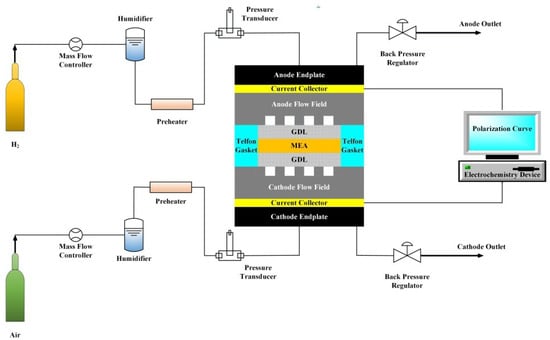
Figure 1.
Schematic diagram of Hydrogenics® test system G60.
2.2. Fixture and Operation Conditions
The membrane used in the fuel cell is Nafion™ 117 purchased from Alfa-Aesar. The carbon cloth electrodes for the anode and cathode sides are purchased from BCS Fuel Cells. The platinum catalyst loading is 0.4 mg cm2. The membrane electrode assemblies (MEA) is assembled and hot pressed in-house. The MEA with an electrode area of 44 cm2 is assembled by two end-plates, two gold-coated copper plates, two graphite plates with 44 cm2 single serpentine flow fields, and two Teflon® gaskets. The gold-coated copper plates are used to collect the current from the cell. The Teflon® gaskets are used to avoid gas leakage and control the compression ratio of GDL thickness. The single serpentine flow field used at the anode side has 1 mm channel depth, 1 mm channel width, and 1 mm land width. The four single serpentine flow fields used at the cathode side all have 1 mm channel depth, 1 mm channel, but their land widths are 0.5 mm, 1 mm, 1.5 mm, and 2 mm, respectively, shown as Figure 2.
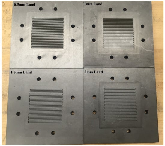
Figure 2.
Single serpentine flow fields with four different land widths (0.5 mm, 1 mm, 1.5 mm, 2 mm).
A series of experiments with three different air inlet flow rates of 0.5, 1, and 2 L/min are conducted at the cathode side using four different cathode flow fields, respectively. The hydrogen inlet flow rate at the anode side is kept at 0.5 L/min. The cell operating temperature, inlet gas temperatures of the anode and cathode sides of the fuel cells are maintained at 70 °C. The dew point of both anode and cathodes gases are kept at 70 °C to ensure fully humidified gases. No back pressure is applied in the experiments, and the outlet pressure on both anode and cathode is kept at ambient pressure.
Before the actual experiment, a break-in procedure with MEA humidification and catalyst activation is applied. In the present work, in obtaining the polarization curves, the voltage is changed from open-circuit potential (OCV) of the cell to 0.25 V with a step of 0.05 V. At each voltage stage, the current and voltage values are collected only after the cell has reached stead-state conditions.
3. Results and Discussions
3.1. Influence of Inlet Flow Rates
Figure 3 shows the current density of different operating potentials at different inlet flow rates. As the flow rate increases, the current densities at less than 0.6 V cell potentials, always increase in all the four different land width cases. This result is consistent with the findings in the previous literature [20]. The reason is that the available reactant gas to the catalyst layer increases and excess produced liquid water can be removed easily at a higher inlet flow rate. Therefore, the mass transfer loss is lower at a higher inlet flow rate.
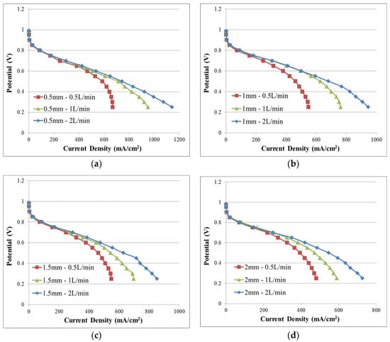
Figure 3.
Comparison of polarization curves at different inlet flow rates: (a) Land width = 0.5 mm; (b) land width = 1 mm; (c) land width = 1.5 mm; (d) land width = 2 mm.
The pressure drop from the inlet to the outlet at high flow rates is higher, and this can lead to a higher pumping power. The pumping power () can be calculated from the pressure drop and inlet flow rate from the following equation.
where is the pumping power, is the pressure drop from the inlet to the outlet, is the inlet flow rate, and is the pumping efficiency and assumed to be 0.8 in this study. The average pressure drop from the inlet to the outlet at different inlet flow rates during the fuel cell operating are listed in Table 1. The pressure drop increases significantly with the inlet flow rate due to the high gas velocity along the channel and more produced liquid water. The pressure drop decreases significantly when the land width increases from 0.5 mm to 1 mm, since the total channel length is decreased significantly for a fixed flow field area. However, when the land width further increases from 1 mm, the pressure drop does not vary too much with the decrease of the total channel length, since the low under-land cross-flow rate for larger land widths cannot effectively remove the excess product liquid water, and accumulated liquid water in the flow field increases the pressure drop. Since the inlet flow rate on the anode is kept at a low level and no liquid water is produced at the anode side, the pressure drop at the anode side is low and the pumping power at the anode side is not considered in this study.

Table 1.
Average pressure drop at different inlet flow rates for four different serpentine flow fields at the cathode side.
Figure 4 displays the net power densities at different operating potentials and different inlet flow rates after considering the pumping power. It can be seen that the net power density does not vary too much at 0.7 V for all the four flow fields when the inlet flow rate increases from 0.5 L/min to 1 L/min. At a high cell potential, the high flow rate increases the amount of reactant gas available to the catalyst layer, but this benefit is just enough to compensate the high pumping power. The maximum net power density occurs at 0.6 V and 0.5 V when the inlet flow rate is at 1 L/min, owing to a suitable balance between the amount of reactant gas to the catalyst layer and the pumping power. At 0.4 V, the net power density does not vary too much from 1 L/min to 2 L/min, except for the case with 0.5 mm land width. At a low cell potential, current density is high and a large amount of liquid water is produced, and the mass transfer loss becomes an important factor for fuel cell performance. The high inlet flow rate decreases the mass transfer loss, and this can compensate the high pumping power at a low cell potential, i.e., 0.4 V. Therefore, when the pumping power is considered, there is an optimal inlet flow rate to maximize the fuel cell performance for each operating condition, listed in Table 2. Normally, the optimal inlet flow rate is 1 L/min for these four serpentine flow fields, instead of the maximum flow rate as the literature reported [20].
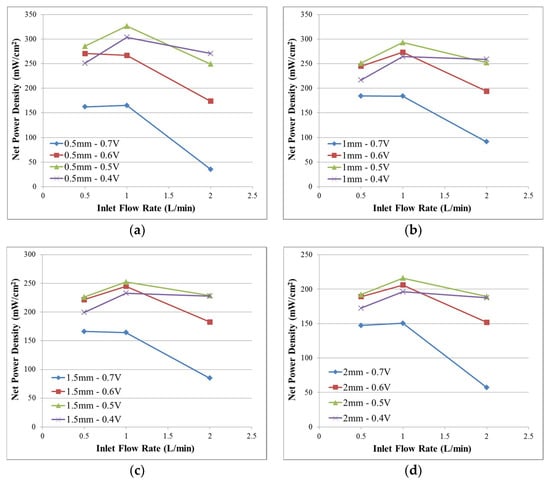
Figure 4.
Comparison of net power densities that include the pumping power at different inlet flow rates and different land widths: (a) Land width = 0.5 mm; (b) land width = 1 mm; (c) land width = 1.5 mm; (d) land width = 2 mm.
Table 2.
Optimal inlet flow rate for four single serpentine flow fields with different land widths at different cell potentials when the pumping power is considered.
3.2. Influence of Land Width
Figure 5 shows the performance of PEM fuel cell with different land widths. As the land width decreases from 2 mm to 0.5 mm, the current densities always increase when the cell potentials are at 0.6 V or lower for all the inlet flow rates. Even at a low inlet flow rate, i.e., 0.5 L/min, the high under-land cross-flow rate caused by decreasing the land width still significantly increases the water removal capability and significantly decreases the mass transfer loss, and this phenomenon is consistent with the findings in the literature [28]. The single serpentine flow field with 0.5 mm land width always has the best performance when the pumping power is not considered. These results agreed with the previous literature [23,26], as the decrease in the land width leads to an increase of fuel cell performance.
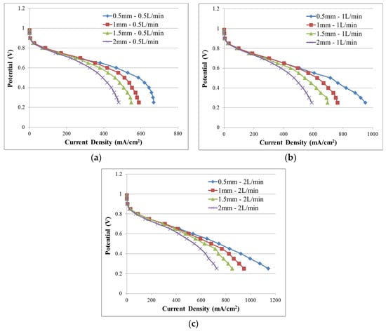
Figure 5.
Comparison of polarization curves at different land widths: (a) Inlet flow rate = 0.5 L/min; (b) inlet flow rate = 1 L/min; (c) inlet flow rate = 2 L/min.
Figure 6 shows the net power densities with different land widths taking into consideration of the pumping power. At a low inlet flow rate (e.g., 0.5 L/min), the net power densities for the 0.5 mm land width case out-perform the other cases when the cell potential is 0.6 V or lower. At a medium inlet flow rate (e.g., 1 L/min), the net power densities for the 0.5 mm land width case out-perform the other cases when the cell potential is 0.5 V or lower. At a high inlet flow rate (i.e., 2 L/min), the net power densities for the 0.5 mm land width case out-perform the other cases only when the cell potential is at 0.4 V. Thus, when the inlet flow rate is higher, the higher under-land cross-flow rate caused by a narrower land only benefits the fuel cell performance at the lower cell potential region. The reason is that the high inlet flow rate leads to a higher pumping power. As a result, the benefit of narrow land width on fuel cell performance is lower at higher inlet flow rates for single serpentine flow fields when the pumping power is considered. Table 3 lists the optimal land width at different inlet flow rates and different cell potentials, and the narrowest land width (i.e., 0.5 mm) does not always result in the best performance when the pumping power is considered. As a result, the optimal flow field by decreasing the land width as the literature stated [23,26] is not valid when pumping power is considered.
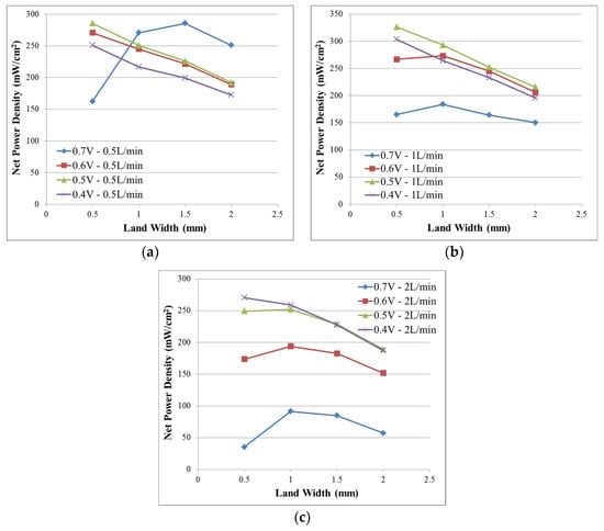
Figure 6.
Comparison of net power densities that include the pumping power at different land widths: (a) Inlet flow rate = 0.5 L/min; (b) inlet flow rate = 1 L/min; (c) inlet flow rate = 2 L/min.
Table 3.
Optimal land width in single serpentine flow fields at different inlet flow rates and different cell potentials when the pumping power is considered.
4. Conclusions
Four single serpentine flow fields with different land widths and three inlet flow rates are used in the experiment to study the effect of land width on fuel cell performance. Fuel cell performance for different land widths was evaluated both with and without the consideration of the pumping power. The following conclusions can be made based on the experimental results:
- (1)
- For all the cases with different land width, high inlet flow rate (i.e., 2 L/min) always resulted in high fuel cell performance when the pumping power was not considered, whereas the medium inlet flow rate (i.e., 1 L/min) generally provided the highest fuel cell performance when the pumping power was included.
- (2)
- As the land width decreases, the fuel cell performance without considering the pumping power at 0.6 V cell potential or lower always increases, due to the increase of the under-land cross-flow rate and decrease of the mass transfer loss.
- (3)
- When the pumping power was included, the improvement of fuel cell performance caused by the decrease of the land width only occurred at a lower cell potential at a higher inlet flow rate.
- (4)
- The effects of the land width and inlet flow rate on fuel cell performance when considering the pumping power are very different from that without considering the pumping power.
- (5)
- Without considering the pumping power, the improvement of performance caused by optimizing the land width can be over-estimated, and the inlet flow rate cannot be optimized properly.
Author Contributions
Conceptualization, X.Z. (Xuyang Zhang) and H.L.; methodology, A.H.; experiment and data collection, A.H. and X.Z. (Xuyang Zhang); data analysis, X.Z. (Xuyang Zhang); investigation, X.Z. (Xuyang Zhang) and X.Z. (Xu Zhang); resources, H.L.; writing—original draft preparation, X.Z. (Xuyang Zhang); writing—review and editing, X.Z. (Xuyang Zhang), X.Z. (Xu Zhang) and H.L.; project administration, H.L.
Funding
This research received no external funding.
Conflicts of Interest
The authors declare no conflict of interest.
References
- O’hayre, R.; Cha, S.-W.; Prinz, F.B.; Colella, W. Fuel Cell Fundamentals; John Wiley & Sons: Hoboken, NJ, USA, 2016. [Google Scholar]
- Laramie, J.; Dicks, A. Fuel Cell Systems Explained; John Wiley and Sons: New York, NY, USA, 2003. [Google Scholar]
- Wilberforce, T.; El-Hassan, Z.; Khatib, F.N.; Al Makky, A.; Baroutaji, A.; Carton, J.G.; Olabi, A.G. Developments of electric cars and fuel cell hydrogen electric cars. Int. J. Hydrog. Energy 2017, 42, 25695–25734. [Google Scholar] [CrossRef]
- Zhang, S.; Yuan, X.-Z.; Hin, J.N.C.; Wang, H.; Friedrich, K.A.; Schulze, M. A review of platinum-based catalyst layer degradation in proton exchange membrane fuel cells. J. Power Sources 2009, 194, 588–600. [Google Scholar] [CrossRef]
- Zhang, S.; Yuan, X.; Wang, H.; Merida, W.; Zhu, H.; Shen, J.; Wu, S.; Zhang, J. A review of accelerated stress tests of MEA durability in PEM fuel cells. Int. J. Hydrog. Energy 2009, 34, 388–404. [Google Scholar] [CrossRef]
- Li, X.; Sabir, I. Review of bipolar plates in PEM fuel cells: Flow-field designs. Int. J. Hydrog. Energy 2005, 30, 359–371. [Google Scholar] [CrossRef]
- Tawfik, H.; Hung, Y.; Mahajan, D. Metal bipolar plates for PEM fuel cell—A review. J. Power Sources 2007, 163, 755–767. [Google Scholar] [CrossRef]
- Jung, A.; Kong, I.M.; Baik, K.D.; Kim, M.S. Crossover effects of the land/channel width ratio of bipolar plates in polymer electrolyte membrane fuel cells. Int. J. Hydrog. Energy 2014, 39, 21588–21594. [Google Scholar] [CrossRef]
- Ijaodola, O.; Ogungbemi, E.; Khatib, F.N.; Wilberforce, T.; Ramadan, M.; Hassan, Z.E.; Thompson, J.; Olabi, A.G. Evaluating the Effect of Metal Bipolar Plate Coating on the Performance of Proton Exchange Membrane Fuel Cells. Energies 2018, 11, 3203. [Google Scholar] [CrossRef]
- Kahraman, H.; Orhan, M.F. Flow field bipolar plates in a proton exchange membrane fuel cell: Analysis & modeling. Energy Convers. Manag. 2017, 133, 363–384. [Google Scholar]
- Vinh, N.; Kim, H.-M. Comparison of Numerical and Experimental Studies for Flow-Field Optimization Based on Under-Rib Convection in Polymer Electrolyte Membrane Fuel Cells. Energies 2016, 9, 844. [Google Scholar] [CrossRef]
- Owejan, J.; Trabold, T.; Jacobson, D.; Arif, M.; Kandlikar, S. Effects of flow field and diffusion layer properties on water accumulation in a PEM fuel cell. Int. J. Hydrog. Energy 2007, 32, 4489–4502. [Google Scholar] [CrossRef]
- Wang, X.-D.; Duan, Y.-Y.; Yan, W.-M.; Lee, D.-J.; Su, A.; Chi, P.-H. Channel aspect ratio effect for serpentine proton exchange membrane fuel cell: Role of sub-rib convection. J. Power Sources 2009, 193, 684–690. [Google Scholar] [CrossRef]
- Nam, J.H.; Lee, K.-J.; Sohn, S.; Kim, C.-J. Multi-pass serpentine flow-fields to enhance under-rib convection in polymer electrolyte membrane fuel cells: Design and geometrical characterization. J. Power Sources 2009, 188, 14–23. [Google Scholar] [CrossRef]
- Shimpalee, S.; Greenway, S.; Van Zee, J.W. The impact of channel path length on PEMFC flow-field design. J. Power Sources 2006, 160, 398–406. [Google Scholar] [CrossRef]
- Suresh, P.V.; Jayanti, S.; Deshpande, A.P.; Haridoss, P. An improved serpentine flow field with enhanced cross-flow for fuel cell applications. Int. J. Hydrog. Energy 2011, 36, 6067–6072. [Google Scholar] [CrossRef]
- Zhang, G.; Fan, L.; Sun, J.; Jiao, K. A 3D model of PEMFC considering detailed multiphase flow and anisotropic transport properties. Int. J. Heat Mass Transf. 2017, 115, 714–724. [Google Scholar] [CrossRef]
- Hu, X.; Wang, X.; Chen, J.; Yang, Q.; Jin, D.; Qiu, X. Numerical Investigations of the Combined Effects of Flow Rate and Methanol Concentration on DMFC Performance. Energies 2017, 10, 1094. [Google Scholar] [CrossRef]
- Wilberforce, T.; El-Hassan, Z.; Khatib, F.N.; Al Makky, A.; Baroutaji, A.; Carton, J.G.; Thompson, J.; Olabi, A.G. Modelling and simulation of Proton Exchange Membrane fuel cell with serpentine bipolar plate using MATLAB. Int. J. Hydrog. Energy 2017, 42, 25639–25662. [Google Scholar] [CrossRef]
- Higier, A.; Liu, H. Direct measurement of current density under the land and channel in a PEM fuel cell with serpentine flow fields. J. Power Sources 2009, 193, 639–648. [Google Scholar] [CrossRef]
- Wilberforce, T.; El-Hassan, Z.; Khatib, F.N.; Al Makky, A.; Mooney, J.; Barouaji, A.; Carton, J.G.; Olabi, A.-G. Development of Bi-polar plate design of PEM fuel cell using CFD techniques. Int. J. Hydrog. Energy 2017, 42, 25663–25685. [Google Scholar] [CrossRef]
- Manso, A.P.; Marzo, F.F.; Barranco, J.; Garikano, X.; Garmendia Mujika, M. Influence of geometric parameters of the flow fields on the performance of a PEM fuel cell. A review. Int. J. Hydrog. Energy 2012, 37, 15256–15287. [Google Scholar] [CrossRef]
- Yoon, Y.-G.; Lee, W.-Y.; Park, G.-G.; Yang, T.-H.; Kim, C.-S. Effects of channel configurations of flow field plates on the performance of a PEMFC. Electrochim. Acta 2004, 50, 709–712. [Google Scholar] [CrossRef]
- Akhtar, N.; Kerkhof, P.J.A.M. Effect of channel and rib width on transport phenomena within the cathode of a proton exchange membrane fuel cell. Int. J. Hydrog. Energy 2011, 36, 5536–5549. [Google Scholar] [CrossRef]
- Cooper, N.J.; Smith, T.; Santamaria, A.D.; Park, J.W. Experimental optimization of parallel and interdigitated PEMFC flow-field channel geometry. Int. J. Hydrog. Energy 2016, 41, 1213–1223. [Google Scholar] [CrossRef]
- Liu, H.; Li, P.; Wang, K. Optimization of PEM fuel cell flow channel dimensions—Mathematic modeling analysis and experimental verification. Int. J. Hydrog. Energy 2013, 38, 9835–9846. [Google Scholar] [CrossRef]
- Wang, Y.; Wang, C.-Y.; Chen, K.S. Elucidating differences between carbon paper and carbon cloth in polymer electrolyte fuel cells. Electrochim. Acta 2007, 52, 3965–3975. [Google Scholar] [CrossRef]
- Jiao, K.; Park, J.; Li, X. Experimental investigations on liquid water removal from the gas diffusion layer by reactant flow in a PEM fuel cell. Appl. Energy 2010, 87, 2770–2777. [Google Scholar] [CrossRef]
© 2019 by the authors. Licensee MDPI, Basel, Switzerland. This article is an open access article distributed under the terms and conditions of the Creative Commons Attribution (CC BY) license (http://creativecommons.org/licenses/by/4.0/).