Article

Design of a Single-Phase BLDC Motor for a Cordless Vacuum Cleaner Considering the Efficiency of Airflow

1
Department of Electrical and Computer Engineering, Pusan National University, Busan 46241, Korea
2
Department of Electrical Engineering, Kyungnam University, Changwon 51767, Korea
3
Department of Mechatronics Engineering, Kyungsung University, Busan 48434, Korea
*
Author to whom correspondence should be addressed.
Energies 2019, 12(3), 465; https://doi.org/10.3390/en12030465
Submission received: 27 December 2018 / Revised: 24 January 2019 / Accepted: 28 January 2019 / Published: 1 February 2019
(This article belongs to the Section F: Electrical Engineering)

Abstract

:
This paper discusses an inverter-driven single-phase brushless direct-current (BLDC) motor assembled by a housing for a cordless vacuum cleaner. Air gap in the single-phase BLDC motor is asymmetrically designed to satisfy starting and continuous torque by considering voltage fluctuation in a battery. By varying both advance and conduction angles in response to the change of battery voltage, the proposed single-phase BLDC motor with asymmetric air gap is able to maintain sufficient output power. The system efficiency of a vacuum cleaner driven by the proposed motor assembly is estimated by means of fluid dynamics in air watt, and it is also verified experimentally. From the results of the condition of 100,020 r/min, it was confirmed that the motor efficiency was in good agreement with the estimated efficiency, and air flow efficiency of 45.7% and system efficiency of 41.8% were achieved.

1. Introduction

Consumer electronics markets are rapidly changing from conventional to premium home appliances, with superior performance, convenience, and better design. In line with this, competition among premium products is accelerated in cordless vacuum cleaner applications. A universal motor has been used in a conventional vacuum cleaner, but it is not suitable for a premium cleaner requiring high efficiency with high speed [1]. For this reason, attention is paid to a brushless direct-current (BLDC) motor, but there is a lack of literature and research to support this trend. The BLDC motor uses an electrical commutating mechanism instead of a combination of mechanical commutators and brushes of the universal motor. Hence, it is more widely used in high-speed applications than the universal motor, due to absence of carbon dust output and no required maintenance on brush wear. A single-phase motor is suitable for cordless vacuum cleaners that require smaller size and lighter weight, due to its simple structure compared to a three-phase motor [2,3]. Since a cordless vacuum cleaner is battery powered, it is necessary to analyze the system efficiency, including electric and airflow performance, to get the longer duration of usage. However, most studies focus only on improving the electrical performance [4,5] or flow performance [6,7] of a single-phase BLDC motor for fan applications.
In this study, a single-phase BLDC motor for cordless vacuum cleaners is designed to satisfy starting and continuous torque by considering voltage fluctuation in a battery by means of asymmetric air gap. In contrast with the existing study of single-phase BLDC motors in fan applications [8,9], the variation of DC battery voltage in cordless vacuum cleaners has to be correlated with the ratio of maximum to minimum air gap in a non-uniform stator pole surface. The air gap is asymmetrically designed, and a computational fluid dynamics (CFD) analysis is performed to confirm the system efficiency of the proposed single-phase BLDC motor, including its inverter and fan.

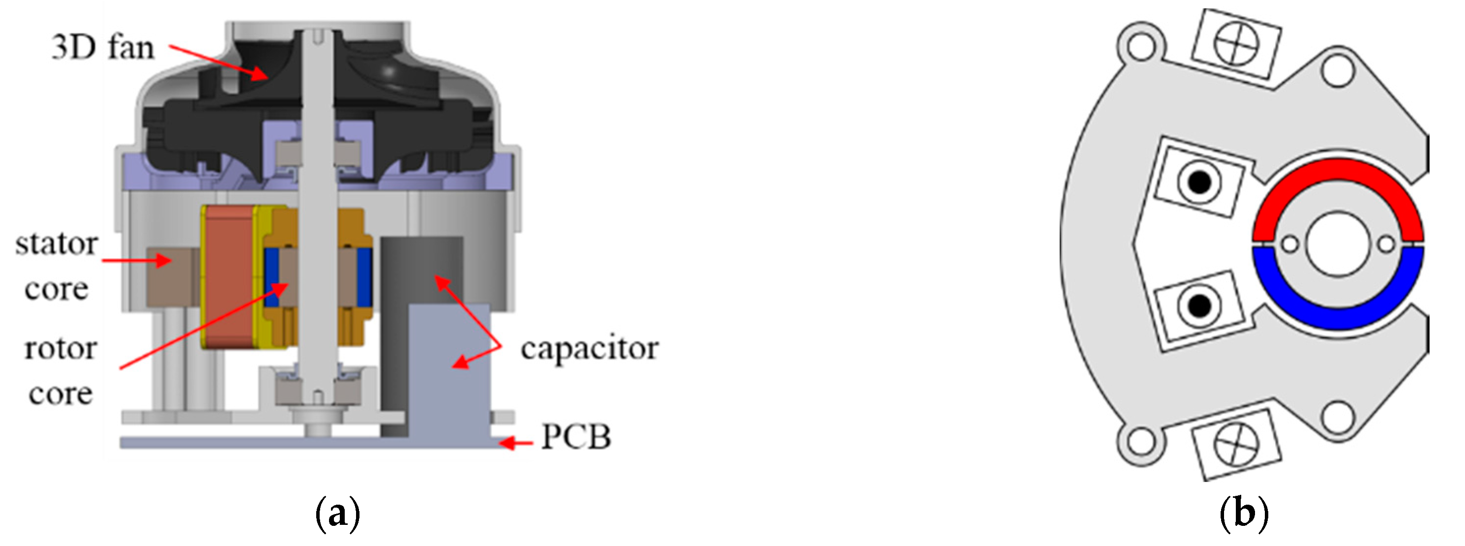
2. Inverter-Driven Single-Phase BLDC Motor

A cordless vacuum cleaner has limited space inside, since a fan, a battery, a filter, a dust collector, an electric motor, and an inverter are assembled under the all-in-one condition. It is very important to reduce the size and weight of a cordless vacuum cleaner in order to improve user convenience and reduce fatigue. Due to a motor driven by an inverter in this paper, miniaturization can be realized by integrating the two components. Figure 1 shows the cross-sectional view of an inverter-driven single-phase BLDC motor unit and the electromagnetic structure of the motor proposed in this paper. Compared to a three-phase BLDC motor having three sets of symmetric windings, a single-phase BLDC motor is more advantageous for space utilization because there is only one set of windings. By applying a single-phase BLDC motor in a cordless vacuum cleaner, a capacitor has to be placed inside the housing together with the motor, as shown in Figure 1a, thereby reducing the overall length of the assembly to achieve miniaturization. In this paper, a single-phase BLDC motor, as shown in Figure 1b, is designed considering starting torque, continuous torque, and battery voltage fluctuation by means of an asymmetric air gap, and the efficiency of air flow is estimated through fluid dynamics at 100,000 r/min speed to confirm system efficiency.

3. Analysis of Proposed Single-Phase BLDC Motor

3.1. Torque Production of a Single-Phase BLDC Motor

Unlike a three-phase BLDC motor having one rotating magnetic field in either clockwise or counterclockwise direction, a single-phase BLDC motor generates two rotating magnetic fields at the same time. The two simultaneous fields spin in rotating directions opposite to each other with respect to time. Therefore, an electromagnetic structure capable of stable starting torque at all rotor positions is indispensable to the design of a single-phase BLDC motor, and hence, asymmetric air gap is generally applied to a single-phase BLDC motor [10,11]. Its electromagnetic torque is the sum of two components, which are cogging and mutual torque generated by a permanent magnet and two magnetic fields, respectively. The two fields are separately created by a permanent magnet and current in stator windings. Electromagnetic total torque is expressed as
T t o t a l = T m u + T c o g
where T m u and T c o g are mutual and cogging torque described by the following equations, respectively.
T m u = i d λ m d θ = i λ ^ m sin ( θ β )
T c o g = 1 2 ϕ m 2 d R d θ = T ^ c o g sin { 2 ( θ γ ) }
where i , λ m , ϕ m , R are current, flux linkage, flux, and reluctance, respectively. Also, θ , β , γ are rotor position, phase angle in mutual torque, and cogging torque, respectively. From Equations (2) and (3), the rotor point at which the mutual and cogging torque is zero should be determined by the phase angle of β and γ at each corresponding torque, respectively.
Figure 2a shows the sum of mutual and cogging torque in a single-phase BLDC motor with symmetric air gap. In this case, phase angles β and γ are synchronized so that zero mutual and zero cogging torque happen at the same time. As a result, there is a dead point in every cycle of total torque, and this situation causes starting failure. Asymmetric air gap should be adopted in a single-phase BLDC motor [10,11].
As given in Figure 2b, the use of asymmetric air gap changing reluctance causes larger variation in the phase angle of γ than the phase angle of β . The reason for this is that the phase angle of γ is more proportional to the rate of change of reluctance with the rotor position, as shown in Equation (3). The variation of phase angle γ and phase angle β causes a phase shift between mutual and cogging torque, as shown in Figure 2b, but there is still negative torque at low levels of current, like in i 2 . In order to generate positive torque at all rotor positions, it is necessary to increase mutual torque by exciting greater amounts of current, like in i 1 . Hence, asymmetry air gap is one of the important design factors to guarantee stable starting torque, continuous torque, and motor efficiency.

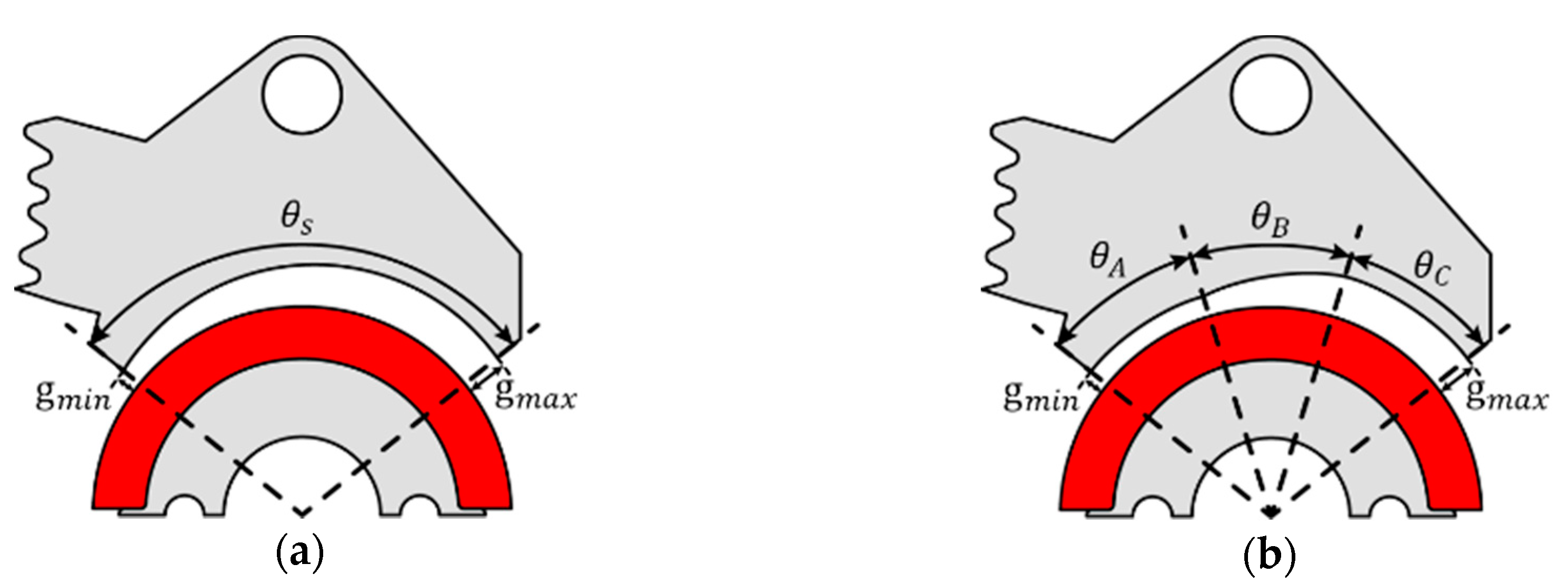
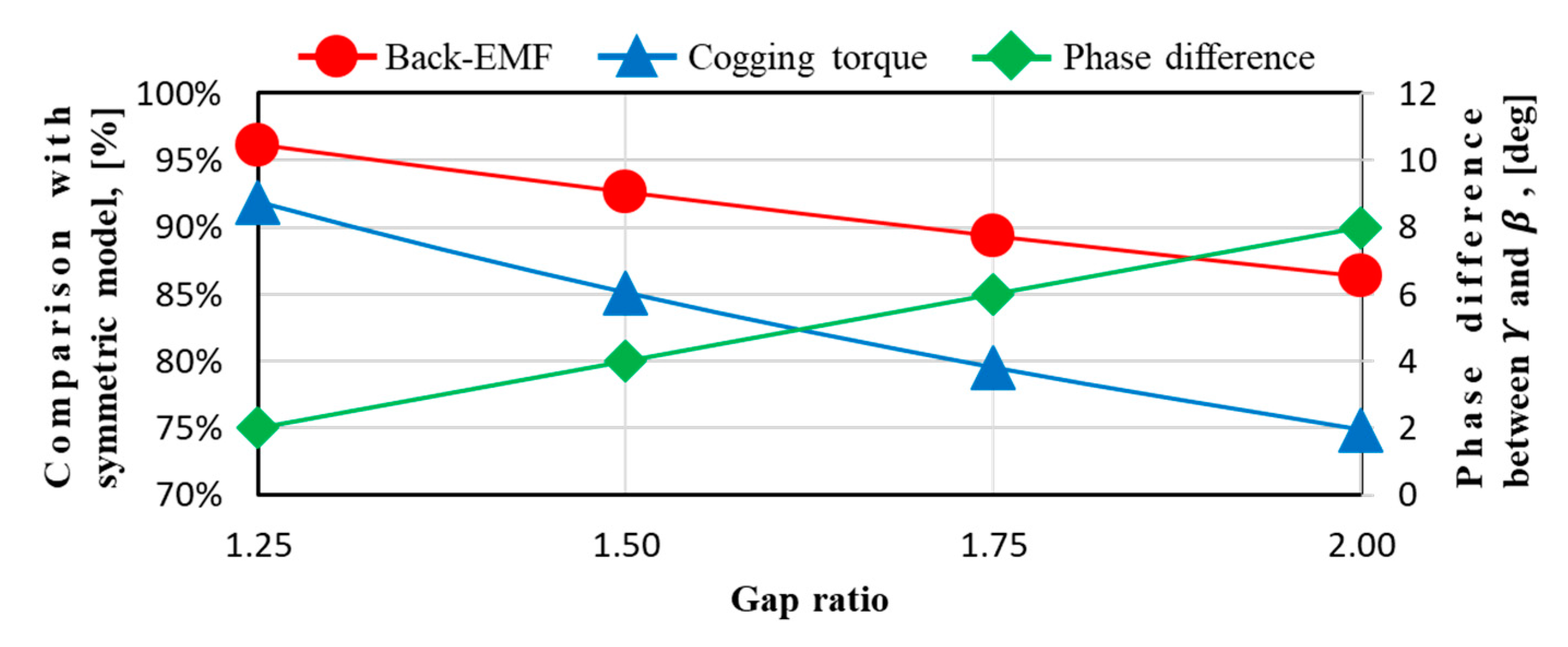
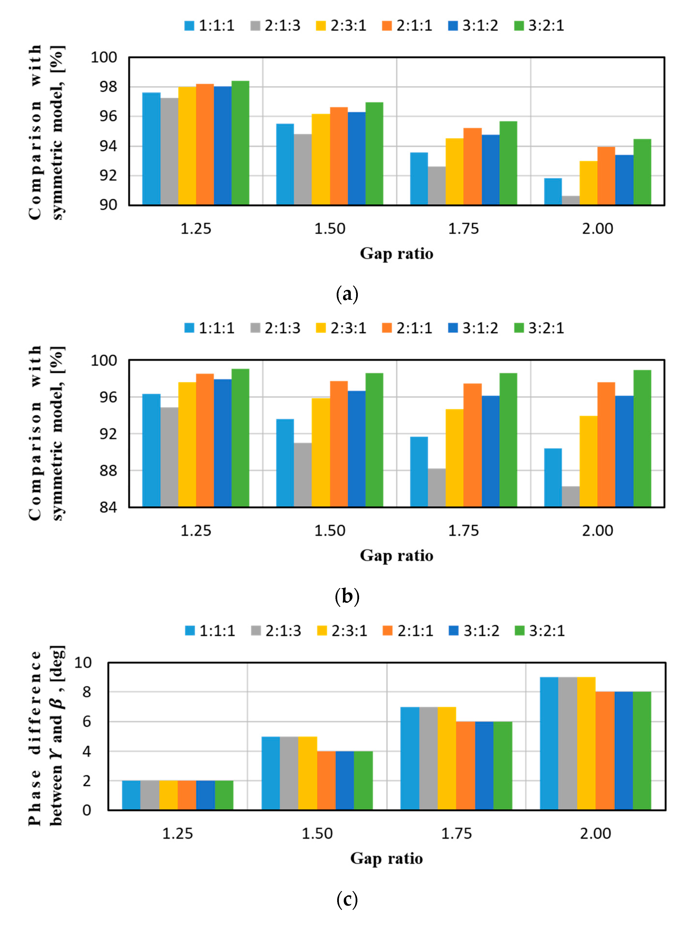
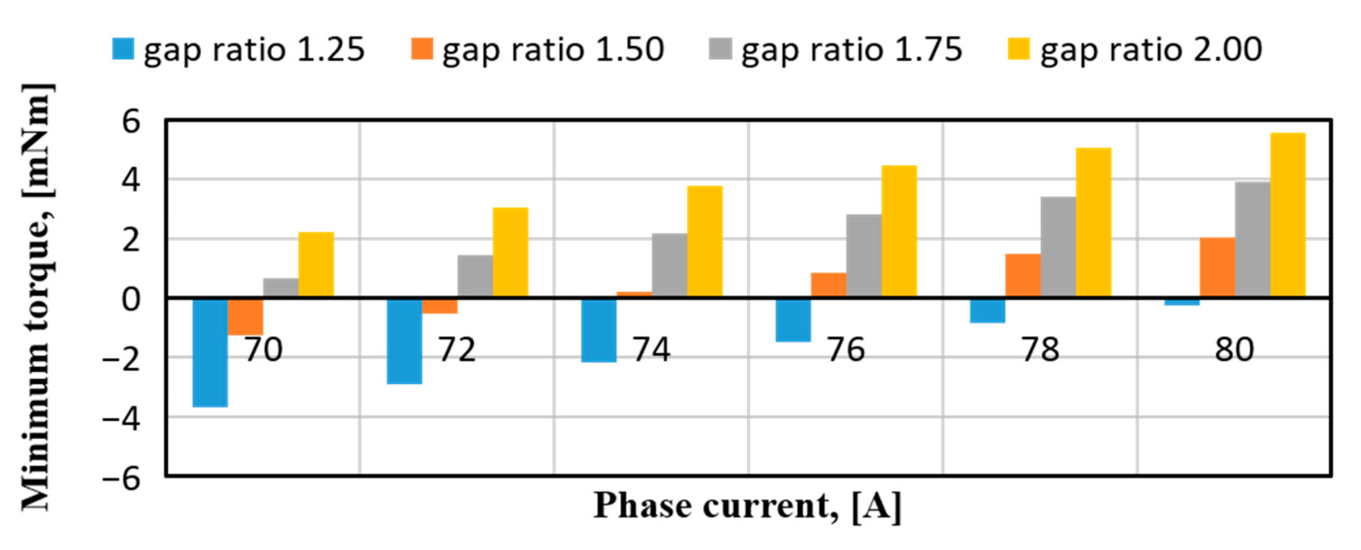
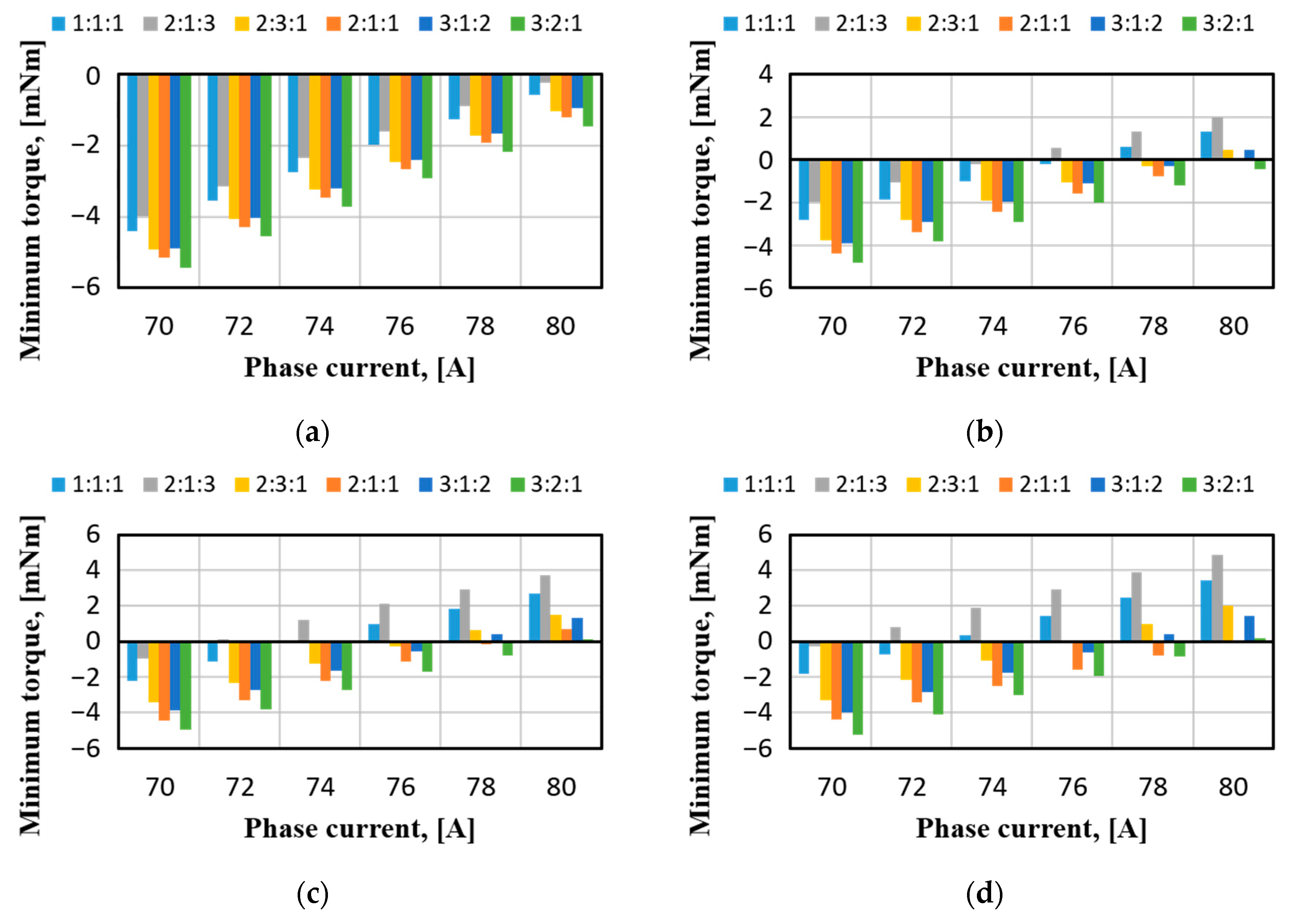
3.2. Design of Asymmetric Air Gap

As given in Figure 3a,b, tapered and stepped types of asymmetric air gap are selected to design a single-phase BLDC motor. In Figure 3a, stator pole surfaces are tapered by using one arc with gradual changes in the length of air gap; in other words, the ratio of minimum to maximum length in air gap is varied. In Figure 3b, stepped air gap has the same ratio of minimum to maximum length as the tapered type, but there are three separate sections of air gap as θ A , θ B , and θ C , illustrated in Figure 3b.
In order to investigate the performance of a single-phase BLDC motor by changing the asymmetry of air gap, four ratios of 1.25, 1.50, 1.75, and 2.00 between minimum and maximum length are chosen and applied to both tapered and stepped structures. In the case of the stepped air gap, three angular portions of θ A , θ B , and θ C are changed in terms of their fraction, and six combinations with respect to θ A , θ B , and θ C are presented in Table 1.
No load performance is compared in tapered and stepped air gap, as shown in Figure 4 and Figure 5, respectively, by employing the ratio of minimum to maximum length from 1.25 up to 2.00. Regardless of type of air gap, the increase of length ratio in air gap reduces back electromotive force (EMF) and cogging torque at the same time, but it increases the phase difference between back-EMF and cogging torque. It is seen that the back-EMF and cogging torque of stepped air gap are larger than those of tapered air gap, since more flux is generated in the stepped structure in direct proportion to average reluctance in air gap.
In Figure 5a,b, the performance of stepped air gap is estimated in terms of ratio of length and angle in the case of no load. By increasing the region of θ A and decreasing the region of θ C compared to θ B , back-EMF and cogging torque is improved, since the fraction of minimum air gap is proportional to average reluctance in its magnetic circuit. Figure 5c shows that phase angle between back-EMF and cogging torque is increasingly shifted as the angle of θ A gets smaller, regardless of angles θ B and θ C , as given in Table 1. This is because cogging torque becomes zero at a point of minimum reluctance.
The characteristics of continuous and starting torque are evaluated in two types of asymmetric air gap by examining minimum torque compared to total torque under the condition of DC current limited from 70 A up to 80 A, considering maximum allowable current of switching devices. Simulation results of tapped and stepped air gap are shown in Figure 6 and Figure 7, respectively.
In the case of tapered air gap, phase difference between back-EMF and cogging torque becomes significant at a ratio of minimum to maximum length in air gap, so that continuous torque and starting torque are the best at a length ratio of 2.0. In the case of stepped air gap, continuous torque starts to be generated at a length ratio of 1.5 or more in air gap, and starting torque characteristic peaks at a stator angle ratio of 2:1:3. The models with the best continuous torque and starting torque are finally selected and research is carried out to confirm the output power and efficiency during inverter control. The final models are tapered air gap with length ratio of 2.0 and stepped air gap with length ratio of 2.0 and stator angle ratio of 2:1:3.

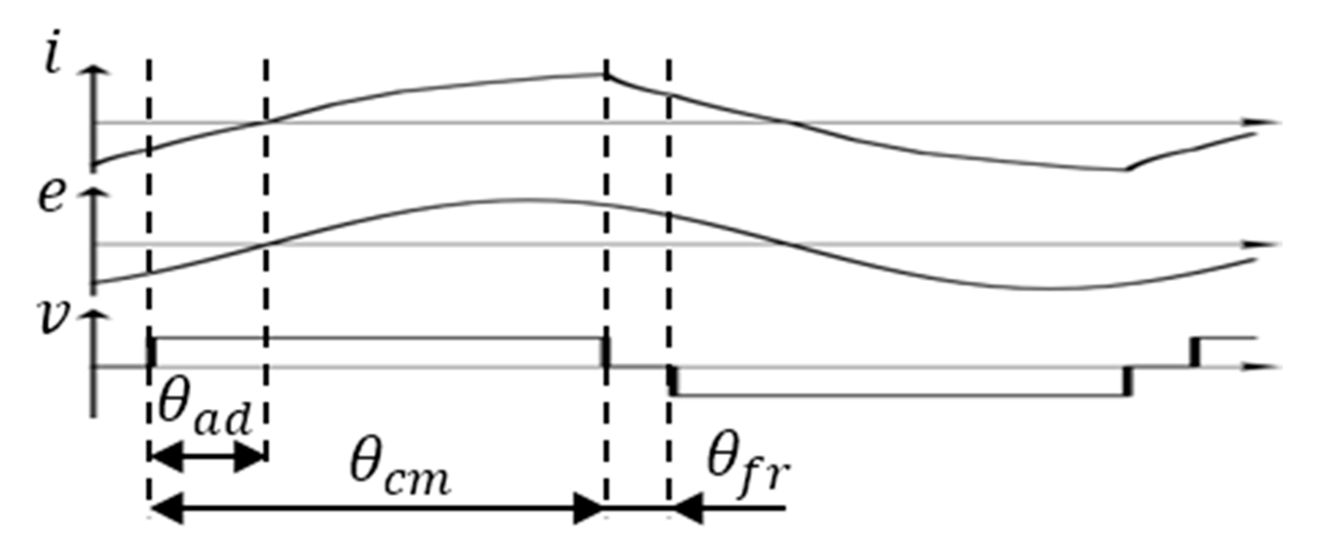
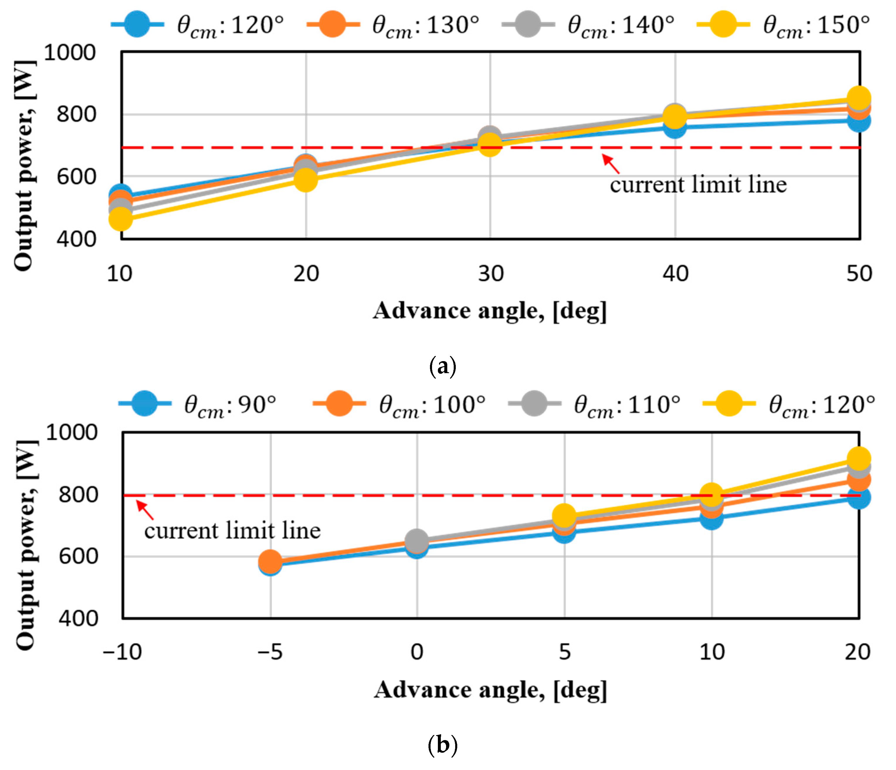
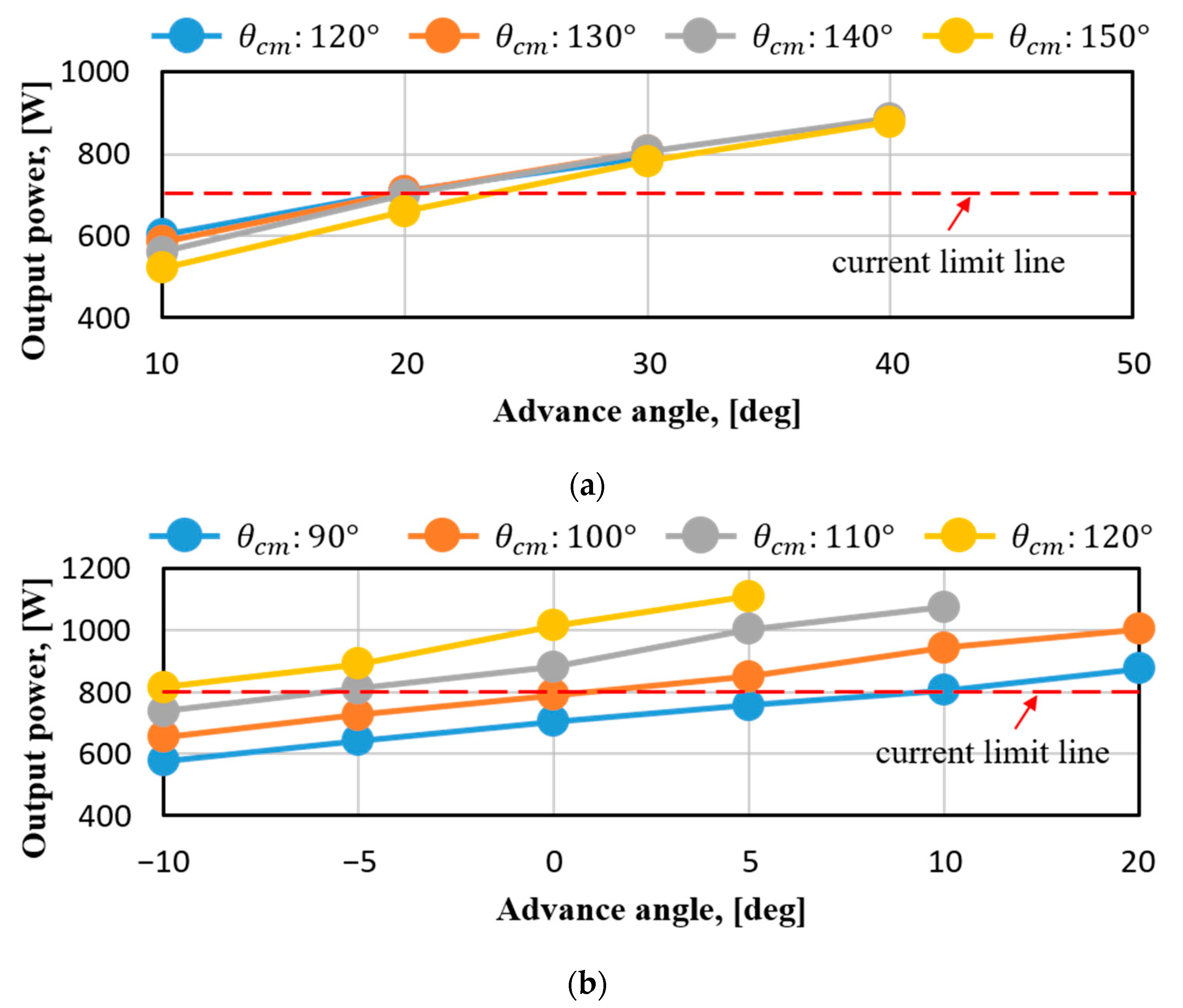
3.3. Control of Single-Phase BLDC Motor

A conventional commutation control with fixed switch on-off angle of a three-phase BLDC motor causes severe current lagging in a cordless vacuum cleaner [12]. The current lagging creates problems of power drop and negative torque generation. Due to the specificity of the cordless design, it is necessary for the controller to maintain constant output power in consideration of battery voltage fluctuation according to the cleaning time. As shown in Figure 8, both advance and conduction angle controls are used to achieve constant power in this paper.
The advance angle and conduction angle technique is to control phase and pulse-width of input voltage. Increasing advance angle θ a d helps the current to rise faster, and thus power is increased. On the other hand, as freewheeling interval θ f r becomes longer by decreasing conduction angle θ c m , power drops. Therefore, it is important to find the combination of advance and conduction angles that correspond to battery voltage fluctuation to maintain the constant output power in a cordless vacuum cleaner.

3.4. Electrical Dynamics of Single-Phase BLDC Motor

Battery voltage is fluctuated between 20 and 26 volts, and output power and efficiency are estimated by varying both advance and conduction angles in response to the change of battery voltage. In terms of minimum and maximum battery voltage, Figure 9 shows output power with respect to advance and conduction angles in the case of tapered air gap with a length ratio of 2.0. The influence of advance angle on output is more dominant than that of conduction angle due to the importance of early rise of current. Considering the maximum current of switching devices, the maximum output is 700 watts and 800 watts in the battery voltage of 20 volts and 26 volts, respectively.
In Figure 10, the output power of stepped air gap is predicted considering the length and angle ratios of air gap are 2.0 and 2:1:3, respectively. Since the output of stepped air gap is same as that of tapered air gap, it is proven that the output of 700 watts is guaranteed in both types of air gap, regardless of battery voltage fluctuation from 20 to 26 volts. The rated condition of a cordless vacuum cleaner is 580 watts at 100,000 r/min, and the performance of the two types of air gap is compared in Table 2 in the case of 20 and 26 volts of battery voltage, respectively. In spite of battery swing, rated torque is maintained in both types of air gap with an approximate efficiency of 94% in the range of 20 and 26 volts. Since continuous and starting torque are relatively better in the tapered air gap, as shown in Figure 6 and Figure 7, in this paper, the tapered air gap is selected for further investigation in a cordless vacuum cleaner.

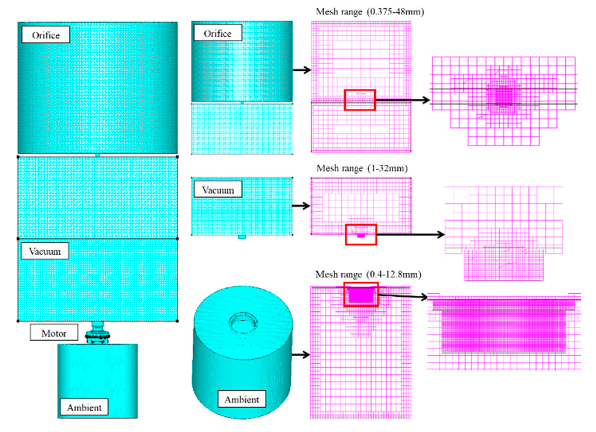
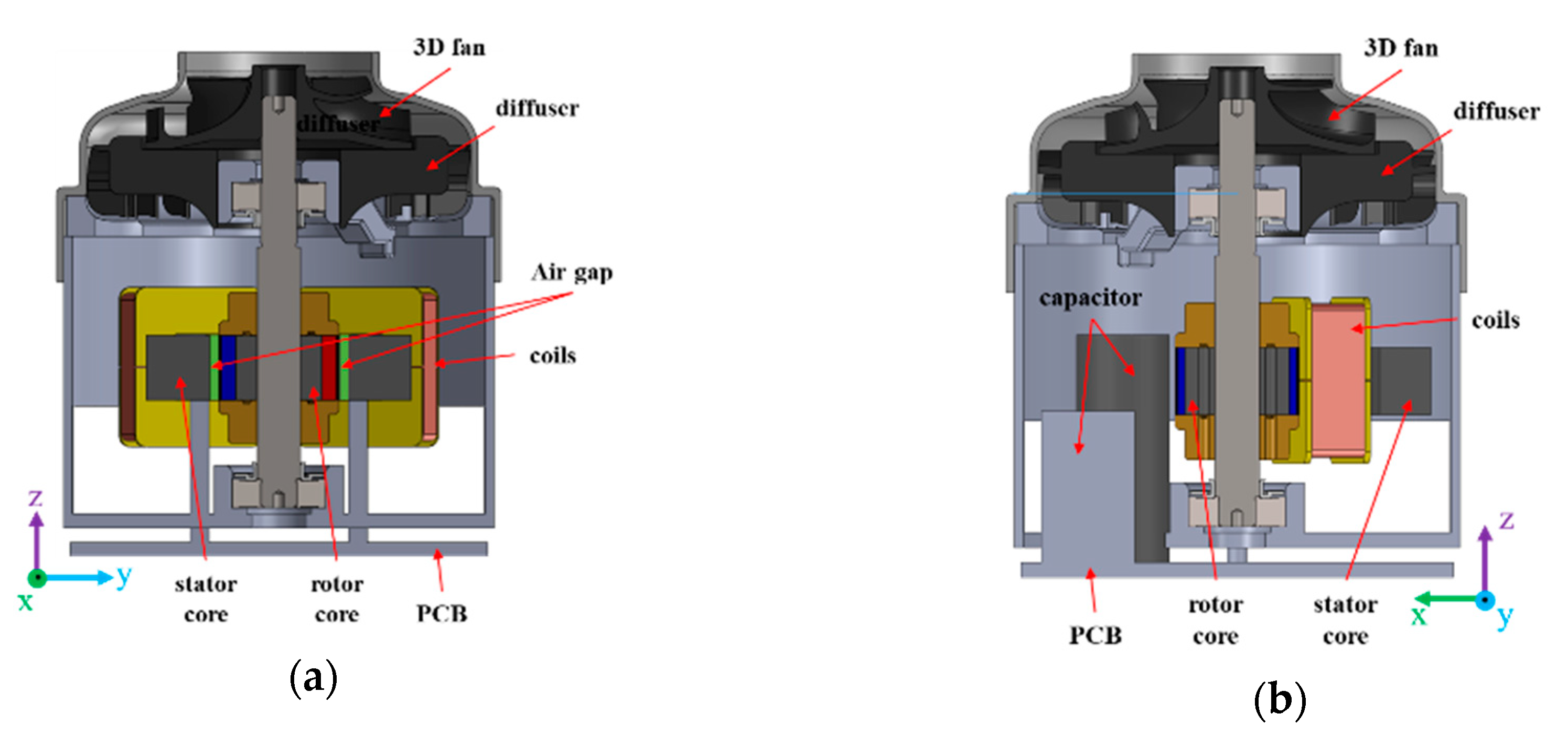
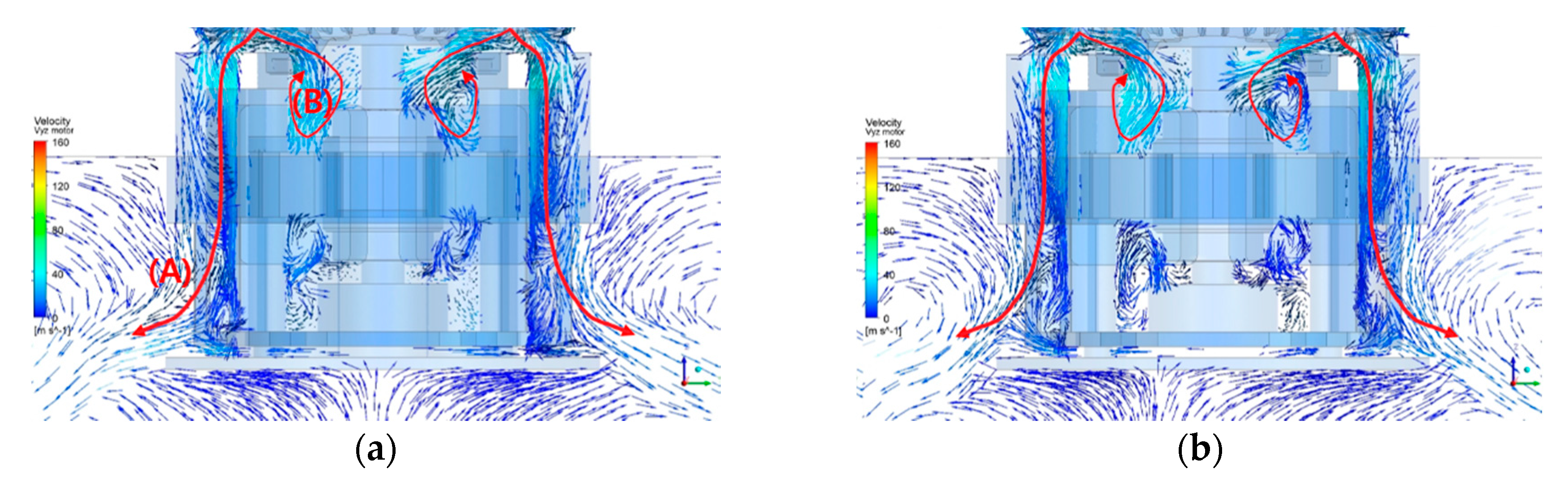
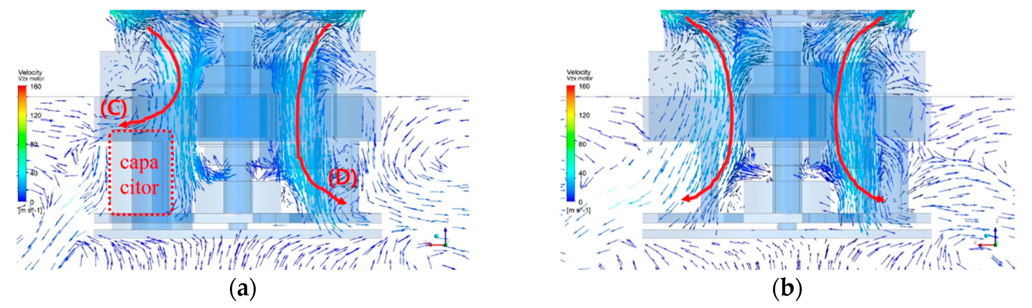
3.5. Fluid Dynamics of Single-Phase BLDC Motor

Figure 11 shows an entire simulation modeling to estimate the fluid dynamics of a single-phase BLDC motor assembled by the housing of Figure 1a inside a vacuum cleaner. The volume of the orifice and vacuum chambers is modeled as a cylinder with a diameter of 500 mm. However, the ambient part is much smaller than the orifice. The dimensions of all regions are set equal to the test conditions of a commercial cordless vacuum cleaner. More detailed simulation conditions for CFD analysis are described in the paper [13]. The efficiency of air flow is determined by the flow rate of air ( Q ) and the average pressure of air on the entire surface of the vacuum (Pa), as given in Equation (4).
η = P a i r [ W ] P s h a f t [ W ] = P a [ Pa ] × Q [ m 3 / s ] T [ Nm ] × ω [ rad / s ]
where P s h a f t , T , ω are the power of shaft, torque, and speed, respectively.
Figure 12 shows the assembly of a single-phase BLDC motor for a cordless vacuum cleaner and its cross-sectional view along the plane of y-z and x-z. In Figure 12b, it is seen that the placement of capacitors makes air flow asymmetric inside the housing. Therefore, in this paper, the effect of capacitors on air flow is calculated in terms of fluid dynamics by comparing CFD results with and without capacitors at the same time.
Figure 13 and Figure 14 show CFD results based on the presence and absence of capacitors in terms of the velocity vectors of air along the plane of y-z and x-z, respectively. In Figure 13a, with capacitors, air leaving from the diffuser is divided into two paths, and the first path of air along the line of (A) goes straight out of the housing. The second path of air is the contour of (B), where the vortex is generated by air colliding with either a rotor assembly, a stator assembly, or coils. Compared to Figure 13a, similar flows of air exist in Figure 13b without capacitors, and it is noted that airflow does not depend on capacitors along the plane of y-z. In Figure 14, on the other hand, airflow is different in terms of whether there are capacitors or not. From Figure 14a,b, there is no distinct difference in the airflow of (D) passing between the diffuser and the stator slot. However, the capacitors below the flow path of (C) in Figure 14a affect airflow, and the efficiency of airflow is changed compared to Figure 14b. Table 3 shows the comparison of the efficiency of airflow with and without capacitors. From the CFD results, the gap in the efficiency of airflow due to the presence and absence of capacitors is 0.2%, which is not significant compared to the efficiency of a motor in Table 2.

3.6. Experimental Verification of Efficiency in Airflow

Figure 15 illustrates the prototype of a single-phase BLDC motor assembled by its housing for a cordless vacuum cleaner proposed in this paper. The prototype assembly has been tested at a speed of 84,468 r/min up to the rated speed of 100,020 r/min, and experimental results are detailed in Table 4.
Due to difficulties in completely matching experimental testing conditions at 100,000 r/min during the initial design of a single-phase BLDC motor, there is a gap between estimation in Table 3 and measurement in Table 4. Because of that, the measured output at 100,020 r/min is 412.2 watts, which is approximately 71% of its rated value given in Table 2. Also, due to the unusual condition of a vacuum cleaner at high speed compared to other home appliances, it is difficult to reproduce the actual operating situation of a vacuum cleaner on a dynamometer bench, and hence, core loss is included in experimental results to end up with system efficiency, as shown in Table 4.
As shown in Table 4, the experimental results show that motor efficiency goes down slightly as speed increases, and in spite of less output compared to simulation in Table 2, it is noted that the performance of a single-phase BLDC motor designed in this paper has been sufficiently verified by experiments. Since pressure and air flow are linearly proportional to speed in the range of 80,000 up to 100,000 r/min [10], measured airflow efficiency is approximately 46%. The single-phase BLDC motor assembly proposed for a cordless vacuum cleaner has been tested to show system efficiency of 41.8%, in which motor, inverter, and airflow efficiencies are taken into account together.

4. Conclusions

This paper discusses the design of a single-phase BLDC motor unit for cordless vacuum cleaners and analysis of system efficiency using the CFD analysis. For this, motor design, inverter control, and flow path analysis were performed, and a prototype was fabricated and tested. Two asymmetric air gaps—tapered type and stepped type—were compared to meet the generation of starting torque and continuous torque in a single-phase BLDC motor. In the motor efficiency, both the asymmetric air gaps showed a high efficiency of 94%, and the tapered type performed better in terms of torque ripple and was selected as the final model in this paper. Considering voltage fluctuation in a battery of cordless vacuum cleaners, it was confirmed that the same level of efficiency was maintained by controlling both the advance angle and conduction angle regardless of the voltage fluctuation. The CFD analysis was carried out and the difference in air flow efficiency due to the capacitors inside the motor housing was confirmed to be 0.2%. The final model was fabricated and tested under operating conditions ranging from 84,068 r/min to 100,020 r/min. From the results of the condition of 100,020 r/min, it was confirmed that the motor efficiency was in good agreement with the estimated efficiency, and air flow efficiency of 45.7% and system efficiency of 41.8% were achieved. Because the efficiency of the single-phase BLDC motor and the inverter drive shows a satisfactory level of efficiency, it is necessary to improve air flow efficiency to obtain a high system efficiency. The goal of future research is to improve air flow efficiency through optimum design, considering both the motor core and the housing structure. This study will be used as a reference literature in the design of a single-phase BLDC motor for cordless vacuum cleaners in terms of both motor and system efficiency under the condition of voltage fluctuation in a battery.

Author Contributions

Conceptualization, H.H. and C.L.; software, J.C. and S.H.; formal analysis, H.H. and J.Y.C.; investigation, J.C. and S.H.; data curation, H.H. and J.Y.C.; writing—original draft preparation, H.H.; writing—review and editing, C.L.; project administration, C.L.

Funding

This research received no external funding.

Acknowledgments

This research was supported in part by Basic Science Research Program through the National Research Foundation of Korea funded by the Ministry of Education under Grant NRF-2018R1D1A1B07049717, and in part by the Basic Research Laboratory through the National Research Foundations of Korea funded by the Ministry of Science, ICT and Future Planning under Grant NRF-2015R1A4A1041584.

Conflicts of Interest

The authors declare no conflict of interest.

References

  1. Jang, K.B.; Won, S.H.; Kim, T.H.; Lee, J. Starting and high-speed driving of single-phase flux-reversal motor for vacuum cleaner. IEEE Trans. Magn. 2005, 41, 3967–3969. [Google Scholar] [CrossRef]
  2. Bentouati, S.; Zhu, Z.Q.; Howe, D. Permanent magnet brushless DC motors for consumer products. In Proceedings of the Ninth International Conference on Electrical Machines and Drives, Canterbury, UK, 1–3 September 1999; Volume 468, pp. 118–122. [Google Scholar]
  3. Sashidhar, S.; Fernandes, B.G. Comparison of a ferrite based single, three-phase spoke and surface permanent magnet BLDC motor for a PV submersible water pump. In Proceedings of the IEEE International Conference on Industrial Technology, Seville, Spain, 17–19 March 2015; pp. 671–676. [Google Scholar]
  4. Chiu, C.-L.; Chen, Y.-T.; Liang, Y.-L.; Liang, R.-H. Optimal driving efficiency design for the single-phase brushless DC fan motor. IEEE Trans. Magn. 2010, 46, 1123–1130. [Google Scholar] [CrossRef]
  5. Fazil, M.; Rajagopal, K.R. A novel air-gap profile of single-phase permanent-magnet brushless DC motor for starting torque improvement and cogging torque reduction. IEEE Trans. Magn. 2010, 46, 3928–3932. [Google Scholar] [CrossRef]
  6. Kale, P.P.L.; Patil, M.B.; Korade, D.N.; Jagtap, K.R. Experimental and CFD analysis of vacuum cleaner exhaust muffler. J. Mech. Civ. Eng. 2016, 13, 21–27. [Google Scholar]
  7. Li, H. Fluid flow analysis of a single-stage centrifugal fan with a ported diffuser. Eng. Appl. Comput. Fluid Mech. 2009, 2, 147–163. [Google Scholar] [CrossRef]
  8. Park, Y.-U.; Cho, J.-H.; Kim, D.-K. Cogging torque reduction of single-phase brushless DC motor with a tapered air-gap using optimizing notch size and position. IEEE Trans. Ind. Appl. 2015, 51, 4455–4463. [Google Scholar] [CrossRef]
  9. Dunkl, S.; Muetze, A.; Schoener, G. Design constraints of small single-phase permanent magnet brushless DC drives for fan applications. IEEE Trans. Ind. Appl. 2015, 51, 3178–3186. [Google Scholar] [CrossRef]
  10. Kimr, H.-C.; Han, J.-H.; Jung, T.-U. Analysis of torque characteristic according to the asymmetrical airgap of the BLDC motor for cooling-fan. In Proceedings of the International Conference on Electrical Machines and Systems, Busan, Korea, 26–29 October 2013; pp. 1277–1280. [Google Scholar]
  11. Bentouati, S.; Zhu, Z.Q.; Howe, D. Influence of design parameters on the starting torque of a single-phase PM brushless DC motor. IEEE Trans. Magn. 2000, 36, 3533–3536. [Google Scholar] [CrossRef] [Green Version]
  12. Zhu, Z.Q.; Bentouati, S.; Howe, D. Control of single-phase permanent magnet brushless dc drives for high-speed applications. In Proceedings of the 8th International Conference on Power Electronics and Variable Speed Drives, London, UK, 18–19 September 2000; pp. 327–332. [Google Scholar]
  13. Son, I.-H.; Noh, Y.; Choi, E.-H.; Choi, J.Y.; Ji, Y.J.; Lim, K. Optimization of the flow path efficiency in a vacuum cleaner fan. J. Mech. Eng. 2018, 64, 258–268. [Google Scholar]
Figure 1. Research prototype of an inverter-driven single-phase brushless direct-current motor unit: (a) system profiles; (b) electromagnetic field structure of a single-phase BLDC motor.
Energies 12 00465 g001
Figure 2. Torque production of a single-phase BLDC motor in terms of air gap type: (a) symmetric air gap; (b) asymmetric air gap.
Energies 12 00465 g002
Figure 3. Two types of asymmetric air gap: (a) tapered air gap; (b) stepped air gap.
Energies 12 00465 g003
Figure 4. No load performance of tapered air gap according to length ratio.
Energies 12 00465 g004
Figure 5. No load performance of stepped air gap according to ratio of length and angle: (a) back-electromotive force; (b) cogging torque; (c) phase difference between back-EMF and cogging torque.
Energies 12 00465 g005
Figure 6. Minimum torque of tapered air gap with respect to length ratio and DC current.
Energies 12 00465 g006
Figure 7. Minimum torque of stepped air gap with respect to DC current and angle ratio: (a) 1.25; (b) 1.50; (c) 1.75; (d) 2.00.
Energies 12 00465 g007
Figure 8. Advance angle and conduction angle controls.
Energies 12 00465 g008
Figure 9. Output power of tapered air gap with respect to switching angles in the case of battery voltage: (a) 20 V; (b) 26 V.
Energies 12 00465 g009
Figure 10. Output power of stepped air gap with respect to switching angles in case of battery voltage: (a) 20 V; (b) 26 V.
Energies 12 00465 g010
Figure 11. Simulation modeling to estimate the fluid dynamics of single-phase BLDC motor inside vacuum cleaner.
Energies 12 00465 g011
Figure 12. Cross-sectional view of motor assembly: (a) plane of y-z; (b) plane of x-z.
Energies 12 00465 g012
Figure 13. Computational fluid dynamic results of plane of y-z: (a) with capacitors; (b) without capacitors.
Energies 12 00465 g013
Figure 14. Computational fluid dynamic results of plane of x-z: (a) with capacitors; (b) without capacitors.
Energies 12 00465 g014
Figure 15. Prototype of single-phase BLDC motor for cordless vacuum cleaner: (a) stator and rotor assembly; (b) housing structure; (c) their assembly.
Energies 12 00465 g015
Table 1. In the case of stepped air gap, angular ratio of three portion of θ A , θ B , and θ C in degrees.
Angular Ratio θ A : θ B : θ C
1:1:12:1:32:3:12:1:13:1:23:2:1
θ A 34.034.034.051.051.051.0
θ B 34.017.051.025.517.034.0
θ C 34.051.017.025.534.017.0
Table 2. Summary of electrical dynamic performance.
ParametersTapered Air GapStepped Air Gap
stack lengthmm9.09.0
gap ratio-2.02.0
turns/poleturns2624
resistanceohm0.0200.017
rotor speedr/min100,000100,000
batteryvolts20262026
torquemNm56.255.555.855.1
currentArms41.740.343.443.2
copper losswatts34.332.028.931.0
core losswatts5.65.85.46.0
outputwatts588.1581.0584.7577.2
efficiency%93.793.994.194.0
torque ripple%168.0240.4182.9254.5
Table 3. Estimation of efficiency in airflow with and without capacitors.
ParametersWith CapacitorsStepped Air Gap
Pressure, Pa12,71412,717
Q i n , L/s12.212.2
T, mNm30.130.0
P a i r , W160.4155.1
P s h a f t , W283.7282.7
Efficiency, %54.754.9
Table 4. Experiment results of the prototype.
ParametersSpeed of Operation, r/min
84,46897,542100,020
input powerwatts283.0420.2451.2
air flow m 3 /min0.6480.7380.753
vacuumkPa151.0196.0204.0
suction powerwatts120.0176.9188.4
currentArms20.327.028.6
copper losswatts9.016.018.0
core losswatts6.06.06.0
motor outputwatts258.5384.1412.2
motor efficiency%95.594.694.5
inverter efficiency%96.796.796.7
airflow efficiency%46.446.145.7
system efficiency%42.442.141.8

