A Rare-Earth Free Magnetically Geared Generator for Direct-Drive Wind Turbines


Abstract
1. Introduction
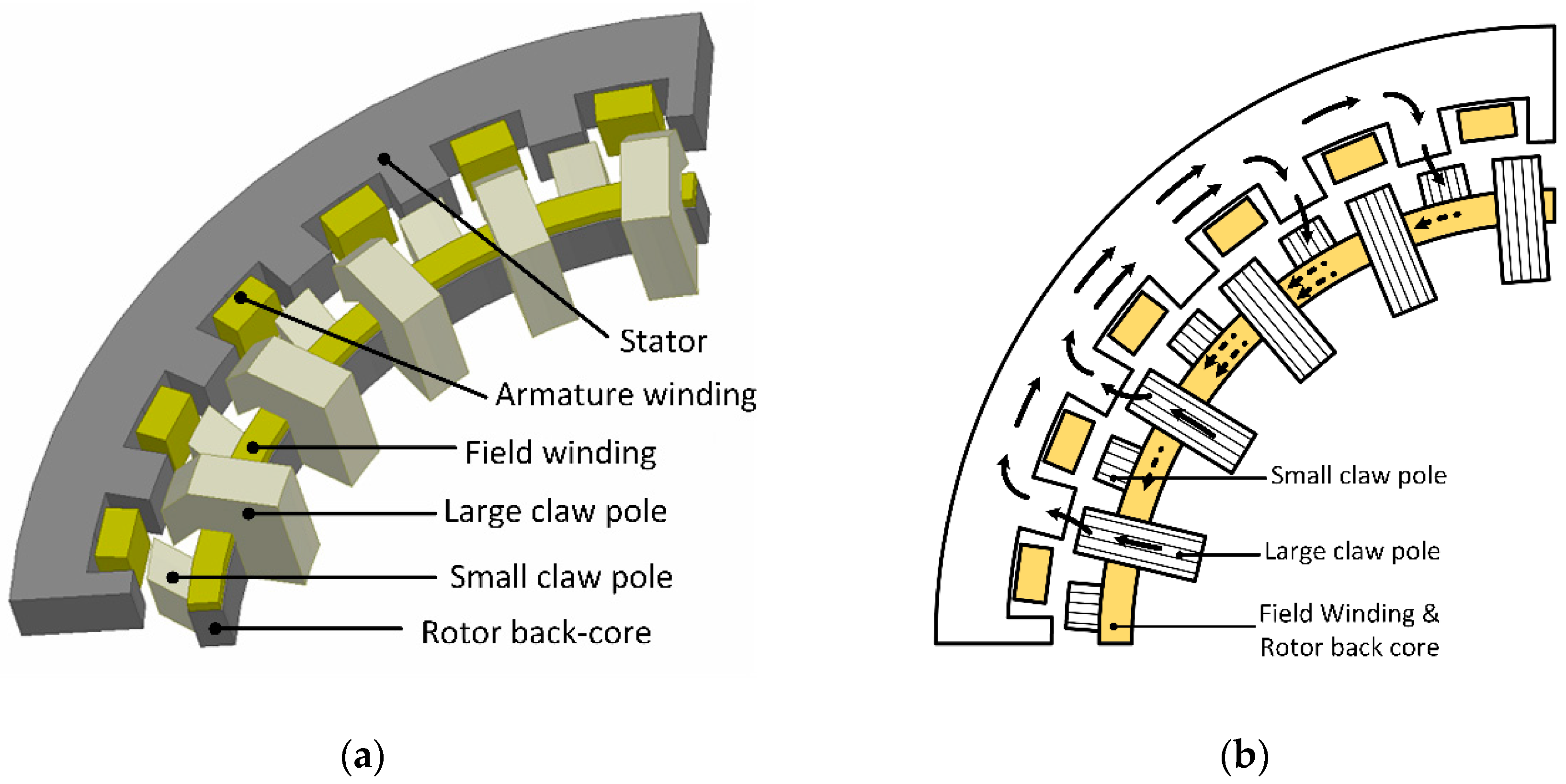
2. Topology and Operation Principle
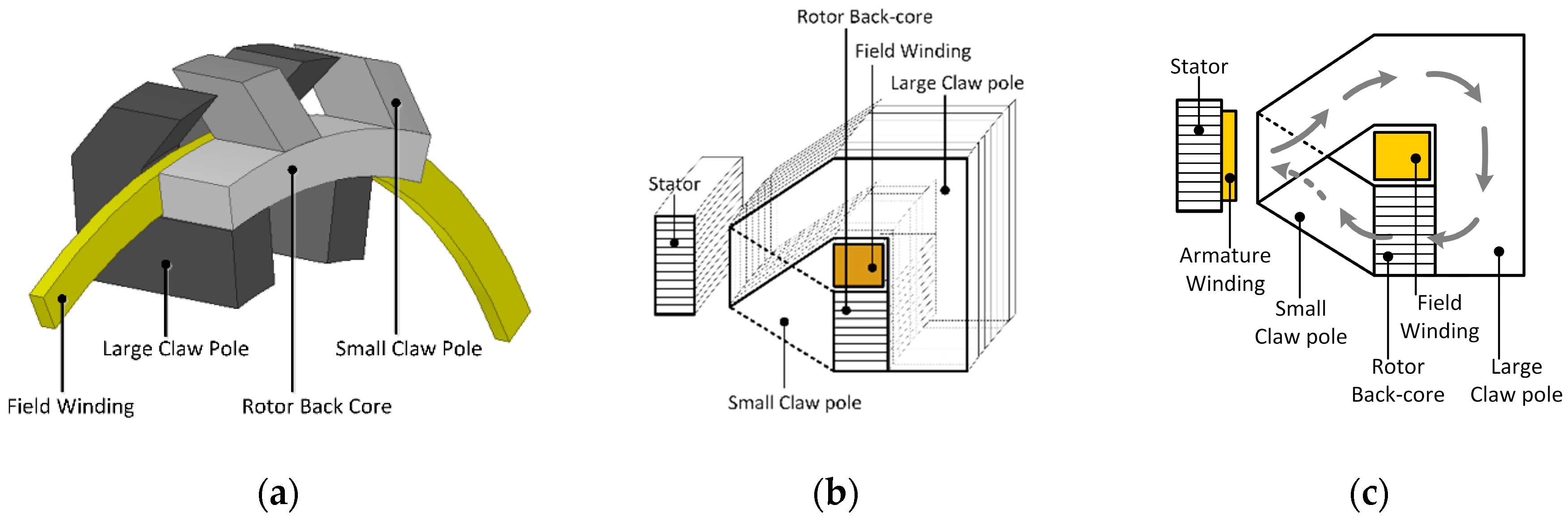
2.1. Generator Topology
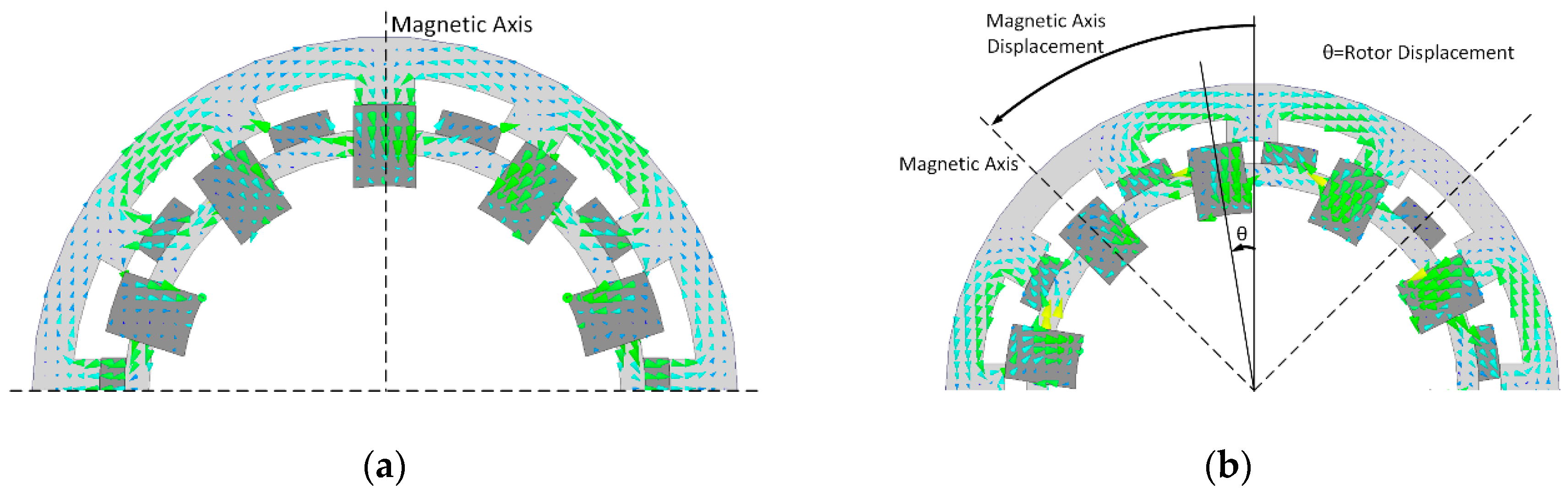
2.2. Operation Principle
3. Design Procedure of EECPV Generator
- Choose an initial value for axial length, Lstk.
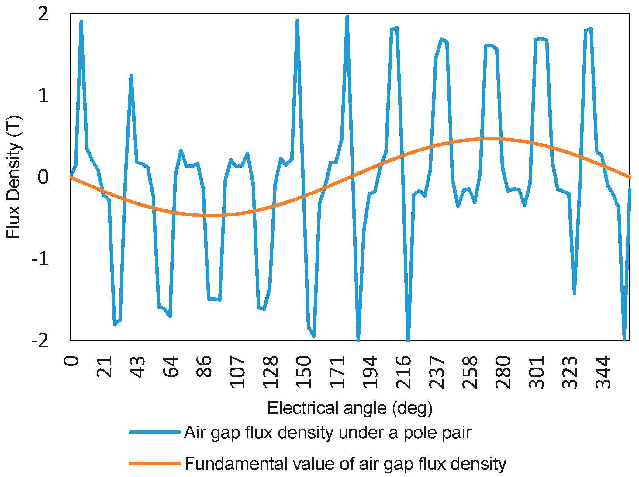
- Establish the primary 3D FE model and obtain Bg
- Calculate values of hsbc and hrbc (shown in Figure 5) analytically using (9) in the terms of estimated Bg and the design vector
- Calculate number of turns per phase using (10).
- Calculate Lstk using (5) for a desired torque.
- Repeat this procedure until Lstk is converged.
4. EECPV Generator for Large Direct-Drive Wind Turbines
4.1. Determination of the Optimum Design Vector
4.2. Designed EECPV Generator
4.3. Structural Mass Optimization
4.4. Comparison
5. Conclusions
Author Contributions
Funding
Conflicts of Interest
References
- Global Wind Energy Council. Global Wind Report 2015—Annual Market Update; Global Wind Energy Council: Brussels, Belgium, 2016; Available online: http://wwwgwec.netlwpcontent/uploads/vip/GWEC-Global-Wind-20 (accessed on 15 December 2018).
- Bilgili, M.; Yasar, A.; Simsek, E. Offshore wind power development in Europe and its comparison with onshore counterpart. Renew. Sustain. Energy Rev. 2011, 15, 905–915. [Google Scholar] [CrossRef]
- Tavner, P. Offshore Wind Turbines Reliability, Availability and Maintenance; The Institution of Engineering and Technology: London, UK, 2012. [Google Scholar] [CrossRef]
- Spinato, F.; Tavner, P.J.; Bussel, G.J.W.V.; Koutoulakos, E. Reliability of wind turbine subassemblies. IET Renew. Power Gener. 2009, 3, 387–401. [Google Scholar] [CrossRef]
- Semken, R.S.; Polikarpova, M.; Roytta, P.; Alexandrova, J.; Pyrhonen, J.; Nerg, J.; Mikkola, A.; Backman, J. Direct-drive permanent magnet generators for high-power wind turbines: benefits and limiting factors. IET Renew. Power Gener. 2012, 6, 1–8. [Google Scholar] [CrossRef]
- Spooner, E.; Williamson, A.C. Direct coupled, permanent magnet generators for wind turbine applications. IEE Proc. Electric Power Appl. 1996, 143, 1–8. [Google Scholar] [CrossRef]
- Yicheng, C.; Pillay, P.; Khan, A. PM wind generator topologies. IEEE Trans. Ind. Appl. 2005, 41, 1619–1626. [Google Scholar] [CrossRef]
- Atallah, K.; Rens, J.; Mezani, S.; Howe, D. A Novel “Pseudo”; Direct-Drive Brushless Permanent Magnet Machine. IEEE Trans. Magn. 2008, 44, 4349–4352. [Google Scholar] [CrossRef]
- Li, H.; Chen, Z. Overview of different wind generator systems and their comparisons. IET Renew. Power Gener. 2008, 2, 123–138. [Google Scholar] [CrossRef]
- Bang, D.J. Design of Transverse Flux Permanent Magnet Machines for Large Direct-Drive Wind Turbines. Ph.D. Thesis, Delft University of Technology, Delft, The Netherlands, 2010. [Google Scholar]
- Zhang, J.; Chen, Z.; Cheng, M. Design and comparison of a novel stator interior permanent magnet generator for direct-drive wind turbines. IET Renew. Power Gener. 2007, 1, 203–210. [Google Scholar] [CrossRef]
- Husain, T.; Hasan, I.; Sozer, Y.; Husain, I.; Muljadi, E. Design considerations of a transverse flux machine for direct-drive wind turbine applications. IEEE Trans. Ind. Appl. 2018, 54, 3604–3615. [Google Scholar] [CrossRef]
- Liu, W.; Lipo, T.A. Analysis of Consequent Pole Spoke Type Vernier Permanent Magnet Machine With Alternating Flux Barrier Design. IEEE Trans. Ind. Appl. 2018, 54, 5918–5929. [Google Scholar] [CrossRef]
- Riba, J.R.; López-Torres, C.; Romeral, L.; Garcia, A. Rare-earth-free propulsion motors for electric vehicles: A technology review. Renew. Sustain. Energy Rev. 2016, 57, 367–379. [Google Scholar] [CrossRef]
- Toba, A.; Lipo, T.A. Generic torque-maximizing design methodology of surface permanent-magnet vernier machine. IEEE Trans. Ind. Appl. 2000, 36, 1539–1546. [Google Scholar]
- Shuangxia, N.; Ho, S.L.; Fu, W.N. A Novel Stator and Rotor Dual PM Vernier Motor With Space Vector Pulse Width Modulation. IEEE Trans. Magn. 2014, 50, 805–808. [Google Scholar]
- Li, D.; Qu, R.; Lipo, T.A. High-Power-Factor Vernier Permanent-Magnet Machines. IEEE Trans. Ind. Appl. 2014, 50, 3664–3674. [Google Scholar] [CrossRef]
- Penzkofer, A.; Atallah, K. Scaling of Pseudo Direct Drives for Wind Turbine Application. IEEE Trans. Magn. 2016, 52, 1–5. [Google Scholar] [CrossRef]
- Liu, C.; Yu, H.; Hu, M.; Liu, Q.; Zhou, S.; Huang, L. Research on a permanent magnet tubular linear generator for direct drive wave energy conversion. IET Renew. Power Gener. 2014, 8, 281–288. [Google Scholar] [CrossRef]
- Penzkofer, A.; Cooke, G.; Odavic, M.; Atallah, K. Coil Excited Pseudo Direct Drive Electrical Machines. IEEE Trans. Mag. 2017, 53, 1–11. [Google Scholar] [CrossRef]
- Liu, C.; Lu, J.; Wang, Y.; Lei, G.; Zhu, J.; Guo, Y. Design Issues for Claw Pole Machines with Soft Magnetic Composite Cores. Energies 2018, 11, 1998. [Google Scholar] [CrossRef]
- Lu, K.; Wu, W. High torque density transverse flux machine without the need to use SMC material for 3-D flux paths. IEEE Trans. Magn. 2015, 51, 1–4. [Google Scholar]
- Gao, Y.; Qu, R.; Li, D.; Li, J.; Zhou, G. Design of a dual-stator LTS vernier machine for direct-drive wind power generation. IEEE Trans. Appl. Supercond. 2016, 26, 1–5. [Google Scholar] [CrossRef]
- Keysan, O.; Mueller, M.A. A transverse flux high-temperature superconducting generator topology for large direct drive wind turbines. Phys. Procedia 2012, 36, 759–764. [Google Scholar] [CrossRef]
- VACUUMSCHMELZE. VacoFlux50. Available online: www.vacuumschmelze.com/index.php?id=126 (accessed on 15 December 2018).
- McDonald, A.; Mueller, M.; Polinder, H. Structural mass in direct-drive permanent magnet electrical generators. IET Renew. Power Gener. 2008, 2, 3–15. [Google Scholar] [CrossRef]
- Bang, D.-J.; Polinder, H.; Ferreira, J.A.; Hong, S.-S. Structural mass minimization of large direct-drive wind generators using a buoyant rotor structure. In Proceedings of the 2010 IEEE Energy Conversion Congress and Exposition (ECCE), Atlanta, GA, USA, 12–16 September 2010; pp. 3561–3568. [Google Scholar]
- Zavvos, A. Structural optimisation of permanent magnet direct drive generators for 5MW wind turbines. Ph.D. Thesis, The University of Edinburgh, Edinburgh, UK, November 2013. [Google Scholar]
- Zavvos, A.; Mcdonald, A.; Mueller, M. Optimisation tools for large permanent magnet generators for direct drive wind turbines. IET Renew. Power Gener. 2013, 7, 163–171. [Google Scholar] [CrossRef]
- Duan, Y.; Harley, R.G. Present and future trends in wind turbine generator designs. In Proceedings of the 2009 IEEE Power Electronics and Machines in Wind Applications, Lincoln, NE, USA, 24–26 June 2009; pp. 1–6. [Google Scholar]
- Snitchler, G. Progress on high temperature superconductor propulsion motors and direct drive wind generators. In Proceedings of the 2010 International Power Electronics Conference—ECCE ASIA, Sapporo, Japan, 21–24 June 2010; pp. 5–10. [Google Scholar]
- Maples, B.; Hand, M.; Musial, W. Comparative Assessment of Direct Drive High Temperature Superconducting Generators in Multi-Megawatt Class Wind Turbines; National Renewable Energy Laboratory (NREL): Golden, CO, USA, 2010.


| Parameter | Definition |
|---|---|
| Ps | Number of pole pairs |
| Fm | Field winding MMF |
| acp | claw-pole arc ratio |
| Dg | Bore diameter |
| g | Air gap length |
| Gr | Gear ratio |
| so | Stator slot opening ratio |
| q | Armature Electric loading |
| Ja | Current Density |
| Parameter | Value |
|---|---|
| Bore diameter, Dg | 7 m |
| Air gap length, g | 5 mm |
| Gear ratio, Gr | 11 |
| Stator slot opening ratio, so | 0.6 |
| Armature Electric loading, q | 70 kA/m |
| Current Density, Ja | 2 A/mm2 |
| Field current density, Jf | 2 A/mm2 |
| Design Parameter | Value |
|---|---|
| Bore diameter, Dg | 7 m |
| Stator axial length, Lstk | 0.36 m |
| Outer diameter | 7.5 m |
| Pole pairs, Ps | 6 |
| Claw-pole arc ratio, acp | 0.65 |
| Tooth width, tw | 122 mm |
| Tooth length, ht | 95 mm |
| Outer stator back core length, hsbc | 116 mm |
| Claw pole length, hcp | 230 mm |
| Claw pole width, wcp | 108 mm |
| Rotor back core length, hrbc | 127 mm |
| Number of turns per phase, Nph | 192 |
| Filed winding turns, Nf | 100 |
| Number of stator teeth | 72 |
| Number of claw pole-pairs | 66 |
| Copper mass | 18.8 t |
| Rotor mass | 33.9 t |
| Stator mass | 11.7 t |
| Total active mass | 64.4 t |
| Performance Parameter | Value |
|---|---|
| Phase current, rms | 1.32 kA |
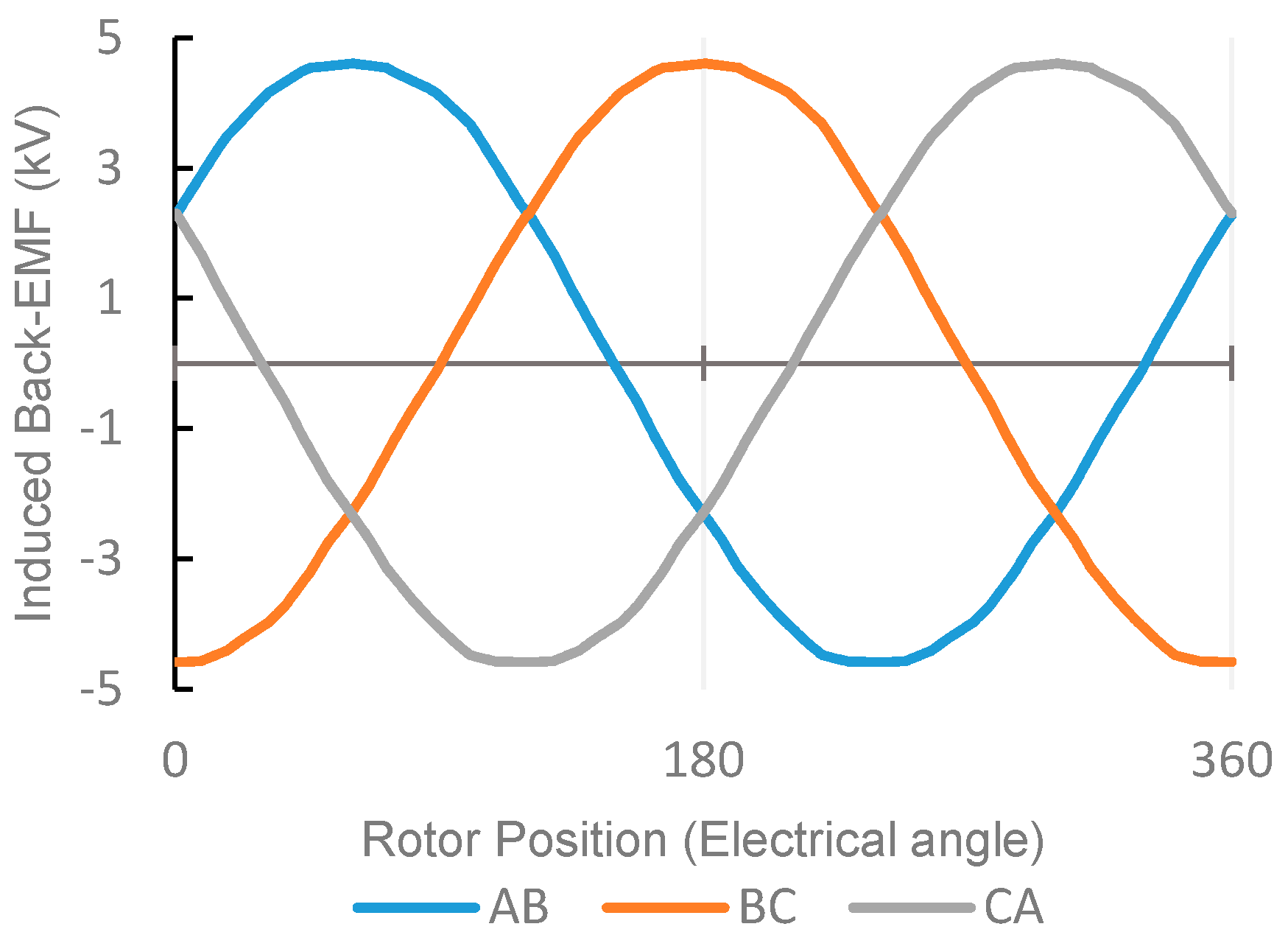
| Line to line Induced EMF, rms | 3.3 kV |
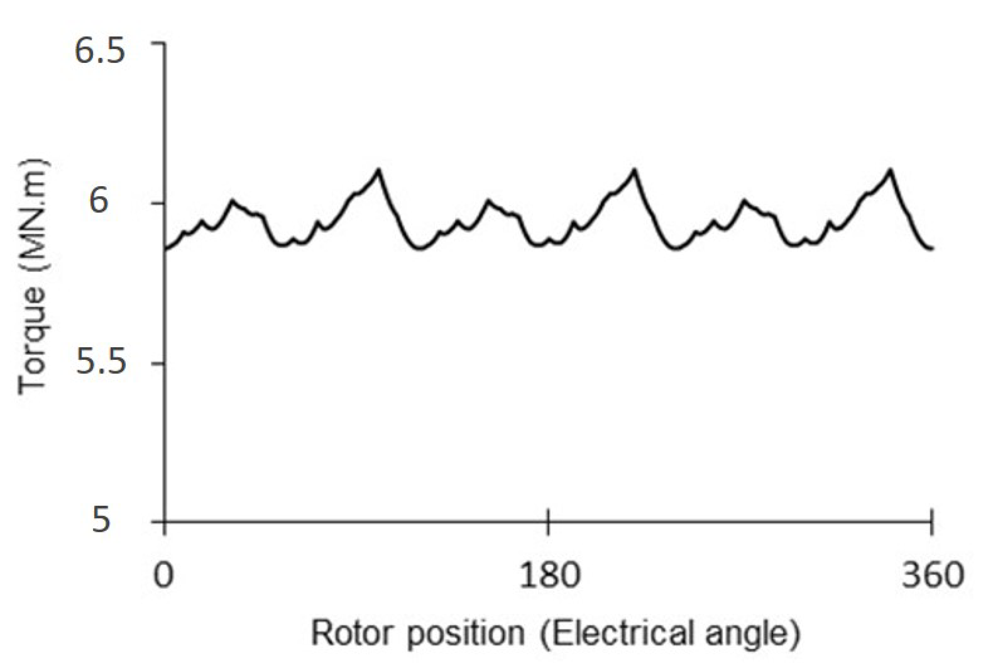
| Torque | 6 MN·m |
| Field winding copper loss | 7.5 kW |
| Armature winding copper loss | 129.7 kW |
| Core losses | 12.5 kW |
| Power factor | 0.61 |
| Efficiency | 98.0% |
| Mass Component | Value | Percentage of Total Mass |
|---|---|---|
| Stator structural mass | 70.8 t | 41% |
| Rotor structural mass | 37.0 t | 21.5% |
| Copper mass | 18.8 t | 11% |
| Stator core mass | 11.7 t | 7% |
| Rotor core mass | 33.9 t | 19.5% |
| Total mass | 172.2 t | 100% |
| Generators | Type | Power (MW) | Speed (rpm) | Torque (MN·m) | Mass (t) | T/Mass (kN·m/t) |
|---|---|---|---|---|---|---|
| Proposed EECPV | EESG * | 7.5 | 12 | 5.97 | 172.2 | 34.7 |
| Enercon E-126 | EESG | 7.5 | 12 | 5.97 | 220 | 27.2 |
| The Switch [30] | PMSG | 3.8 | 21 | 1.73 | 81 | 21.6 |
| NTNU [31] | PMSG | 10 | 13 | 7.35 | 260 | 28.2 |
| NREL-AMSC [32] | PMSG | 6 | 12.3 | 4.66 | 177 | 26.3 |
| NREL-AMSC [32] | PMSG | 10 | 11.5 | 8.3 | 315 | 26.4 |
© 2019 by the authors. Licensee MDPI, Basel, Switzerland. This article is an open access article distributed under the terms and conditions of the Creative Commons Attribution (CC BY) license (http://creativecommons.org/licenses/by/4.0/).
Share and Cite
Zeinali, R.; Keysan, O. A Rare-Earth Free Magnetically Geared Generator for Direct-Drive Wind Turbines. Energies 2019, 12, 447. https://doi.org/10.3390/en12030447
Zeinali R, Keysan O. A Rare-Earth Free Magnetically Geared Generator for Direct-Drive Wind Turbines. Energies. 2019; 12(3):447. https://doi.org/10.3390/en12030447
Chicago/Turabian StyleZeinali, Reza, and Ozan Keysan. 2019. "A Rare-Earth Free Magnetically Geared Generator for Direct-Drive Wind Turbines" Energies 12, no. 3: 447. https://doi.org/10.3390/en12030447
APA StyleZeinali, R., & Keysan, O. (2019). A Rare-Earth Free Magnetically Geared Generator for Direct-Drive Wind Turbines. Energies, 12(3), 447. https://doi.org/10.3390/en12030447