Abstract
In this paper, a real-time energy distribution strategy is designed by a layer-adaptive wavelet transform algorithm and proposed to meet the load power demand while distributing the high-frequency component to supercapacitors and the low-frequency component to batteries in a hybrid energy storage system. In the proposed method, the number of decomposition layers of wavelet transform corresponding to the load power is adaptively determined by dividing the operation zone of supercapacitors into eight cases to respectively distribute the low frequency component to batteries and the remaining high frequency component to supercapacitors. Firstly, since the state of charge of supercapacitors decreases faster as the decomposition layers increases, the state of charge of supercapacitors is divided into eight cases of operation zones. Secondly, since supercapacitors act as the peak power buffer unit, the corresponding number of decomposition layers is finally adaptively determined according to the operation zone of supercapacitors. An experiment testbed is built to verify the effectiveness of the proposed method. Extensive experiment results show that the proposed method provides a better real-time energy sharing between supercapacitors and batteries when compared with the conditional method.
1. Introduction
In recent years, electrical energy has received great attention due to its environmentally friendly and renewable advantages. Electric vehicles (EVs) and urban rail vehicle energy systems are good examples of applications that typically rely on energy sources such as batteries and supercapacitors to store electrical energy [1,2,3,4,5]. Technologies adopted in most electric vehicles are diverse, but they only employ rechargeable batteries. The performance of battery energy management systems relies on the manufacturing technology and the specific application scenarios. Therefore, batteries are highly vulnerable to peak and turbulent energy demand caused by changeable driving road and traffic conditions, which compromise battery life, performance, and battery aging [6].
To address these problems, one solution is to employ batteries and supercapacitors simultaneously to form a hybrid energy storage system (HESS), which profits from supercapacitors as the peak power buffer unit for fluctuating power demand [7]. HESSs have been proposed in many works [8,9,10,11,12]; they combine batteries and supercapacitors and consider their complementary characteristics. Batteries are considered for their high energy storage and supercapacitors are considered for their high power storage in an HESS, which can achieve a higher degree of practicality, such as a longer driving range, and a better performance of acceleration and feedback brake. HESSs route the low-frequency content of power demand into batteries and the high-frequency content into supercapacitors. The separation of power can effectively protect a battery’s life.
In general, an HESS topology can be categorized as three major types: the passive topology, the semi-active topology, and the fully active topology [9]. The passive topology is the simplest and lowest-cost topology. The typical characteristic is the direct connection between batteries and supercapacitors in parallel and directly coupled to a DC bus [10]. Although this topology is easy to implement in EVs, supercapacitors work as a low-pass filter, and the voltage of supercapacitors is limited, which results in their low efficiency. In the semi-active topology, a DC/DC converter is used to connect batteries and supercapacitors [11]. The DC/DC converter permits the voltage of batteries/supercapacitors to be different from that of supercapacitors/batteries. This topology improves the flexibility and performance of the system and can reduce the system cost. The fully active topology employs two DC/DC converters to decouple the batteries and supercapacitors with a DC bus, which meets the required control performance owing to its flexibility of the voltage range in supercapacitors [12]. Nevertheless, this topology demands compromise in terms of cost and efficiency weight volume.
The energy distribution in the hybrid energy system of electric vehicles is a key factor that determines the mileage of electric vehicles [13]. It is particularly important to improve the life cycles of batteries and the overall performance of the HESS. Batteries have a high energy density and a low power density, while supercapacitors have a high power density and a low energy density. Therefore, the energy distribution strategies should distribute the low-frequency power to batteries and the high-frequency to supercapacitors. Many HESS control strategies have been proposed, which are mainly divided into two categories, i.e., off-line approaches and real-time approaches, according to the specific usage in real-time implementation, where the off-line optimization approach is to be used as the benchmark to verify the performance of other methods [14].
Off-line approaches employ advanced optimization algorithms, such as dynamic programming, genetic algorithm, and particle swarm optimization [15,16]. Song et al. [9] adopted a genetic algorithm to solve multi-objective optimization problems, minimizing the total loss of HESSs and battery capacity simultaneously. Choi et al. [15] proposed an convex optimization strategy to achieve the minimization of the magnitude/fluctuation of the current flowing in and out of batteries and the energy loss seen by supercapacitors. Herrera et al. [16] used the genetic algorithm to optimize the energy management system in economic terms, the cost of the energy absorbed from the catenary, and the cost of system operation. However, optimization algorithms are much more complex, which require heavy computation capability and time consumption.
Real-time approaches such as rule-based methods, model predictive control method, and frequency-based methods can achieve real-time energy distribution. A rule-based approach controls the energy flow in the HESS based on rules derived from expert experiences. Trovao et al. [12] proposed a rule-based controller that considers the power demand of the load and the states of charge (SOCs) of batteries and supercapacitors simultaneously. Obviously, the rule-based method does not require any prior knowledge of the road conditions or load. It is developed based on the experience or heuristics of the experts and easily implemented. However, it does not consider the frequency components in the load demand, which is detrimental to battery life. Moreover, these rules are designed based on the initial state of the hybrid energy system and cannot accurately reflect the conditions of the system components after a long period of operation. Wang et al. [13] proposed an average power-based model predictive control to achieve the energy distribution of the vehicle with multiple energy sources without any prior information of the drive cycles. However, model predictive control requires high accuracy of the model. Frequency-based approach methods such as frequency separation method [17] consider high and low frequency components in load power demand, and two filters are used to achieve frequency separation. The cut-off frequency of the filters is switched between three candidate cut-off frequencies to achieve frequency separation. However, the cut-off frequency in the specific case is still fixed, without taking into account the specific changes in load power in specific situations. Li et al. [18] uses three-layer wavelet transform to decompose the load power demand to energy sources. The low frequency components change with the specific load power demand when using wavelet decomposition for frequency separation [19]. Therefore, the wavelet transform can decouple the high and low frequency components in the load demand and change with load demand.
This paper presents a real-time layer-adaptive wavelet transform strategy for the hybrid energy storage system of EVs. The load power demand and the SOC of the batteries and supercapacitors are taken into account to perform the real-time layer-adaptive wavelet transform energy distribution under the role of supercapacitors as the peak power buffer unit in the hybrid energy storage system.
The main contributions are summarized as follows:
(1) A real-time layer-adaptive wavelet transform energy distribution strategy is proposed to meet the load power demand and distribute the load power demand between batteries and supercapacitors. The number of decomposition layers of wavelet transform is determined based on the division of the operation zone of supercapacitors under the role of supercapacitors as the peak power buffer unit in the hybrid energy storage system.
(2) The SOC of supercapacitors is maintained within a predefined range by analyzing the SOCs of batteries and supercapacitors, and the load power demand. Supercapacitors are fully used as the peak power buffer unit to fully satisfy high frequency power.
(3) Extensive experimental results show that the proposed method provides a better real-time energy sharing between supercapacitors and batteries.
This paper is organized as follows. Section 2 introduces the configuration of the hybrid energy management system and models the components in the hybrid energy management system. Section 3 presents the energy distribution strategy proposed in this paper. Verification of experimental results is presented in Section 4. The main conclusions are presented in Section 5.
2. System Configuration and Model
The configuration of the proposed hybrid energy storage system for electric vehicles is shown in Figure 1. According to the high power density of supercapacitors and high energy density of batteries, batteries operate as the primary energy source and supply the low frequency content of power demand, while supercapacitors are considered as the peak power buffer unit that can rapidly offer the high frequency content of power demand. The DC bus voltage should be kept constant in order to transfer power to the load.
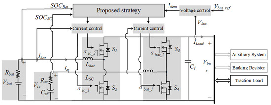
Figure 1.
Configuration of the proposed hybrid energy management system for the electric vehicle (EV).
2.1. The Battery Model
Batteries are characterized by the high energy density and low power density, so it should power the load at a lower rate than supercapacitors. The battery is mainly limited by numbers of its cycle life, hence the proposed strategy should try to avoid batteries facing the charging/discharging power of high frequency components. The battery model in this paper considers a resistor in series with a voltage source [20]. The battery current is , calculated as follows:
where is the input to the battery model, indicating the power absorbed or discharged by the battery. The state of charge is defined as the ratio of the charge in the battery at the i-th moment to its nominal capacity . The SOC of batteries is calculated as follows:
The state of charge is updated as follows:
where is the time step.
The cycle life of batteries depends on its SOC, so the SOC of batteries should be limited to a certain range [21]. When is lower than 20%, the discharge resistance of the battery rapidly increases and the open circuit voltage changes rapidly decrease. Therefore, should be kept above 20%.
2.2. The Supercapacitor Model
Supercapacitors are characterized by high power density and low energy density, so they can respond quickly to high-frequency components in the load, but are limited by its energy. Therefore, supercapacitors act as the peak power buffer unit, outputting power during acceleration and absorbing power during deceleration, respectively. The model considered in this paper for supercapacitors is a capacitor in series with a resistor. The supercapacitor current is calculated as follows:
where , , and represent the charge stored in the supercapacitor, the equivalent capacitance, and the equivalent internal resistance of the supercapacitor, respectively. The charge stored in the supercapacitor is calculated as follows:
where represents the equivalent voltage of the supercapacitor. The state of charge is defined as the ratio of the voltage in the supercapacitor at the i-th moment to its nominal capacity . The SOC of supercapacitor is calculated as follows:
The state of charge is updated as follows:
It is worth noting that the minimum should be maintained above 25%, because the supercapacitor voltage is only half of the nominal voltage and still provides energy [21].
2.3. The DC/DC Converter Model
A fully active topology is adopted in this paper and is comprised of batteries, supercapacitors, and bidirectional DC/DC converters. Compared with semi-active topology, it consumes more energy, but the energy flowing into and out of batteries and supercapacitors can be independently managed and effectively controlled and this topology is therefore more flexible. The bidirectional DC/DC converters boost the low voltage supplied by batteries and supercapacitors to a high DC bus voltage. Assuming that the switching frequency is sufficiently larger than the frequency bandwidth of the circuit, passive elements are invariant and two converters operate in continuous-conduction mode. Based on these assumptions, the average model of the circuit is expressed as follows [22]:
where are control inputs, representing the converter duty ratios for supercapacitors and batteries, respectively. is disturbance. are state vectors, representing the current of supercapacitors and batteries, and the DC bus voltage, respectively. and represent the converter inductance of two DC/DC converters connected in series with batteries and supercapacitors, respectively. represents the DC bus capacity.
2.4. The EV Model
A practical EV model is adopted in this paper with its main characteristics assumed in Table 1 [23]. The Air Resources Board LA92 Dynamometer Driving Schedule (LA92) is selected to estimate the load. LA92 is a representative speed curve that contains a wide range of speeds, including rich high-speed and low-speed conditions, as well as many acceleration and deceleration conditions as shown in Figure 2.

Table 1.
Key characteristics of the EV.
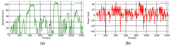
Figure 2.
LA92 dynamometer driving schedule (LA92) used to estimate the load. (a) The speed of LA92; (b) The power of LA92.
The tire rolling resistance is calculated as follows:
The aerodynamic drag is calculated as follows:
The load power includes two conditions, drive power and regenerative power. The load power in the DC bus can then be calculated as follows:
where represents the electrical energy conversion efficiency. represents the kinetic energy feedback efficiency. Their corresponding values are 92% and 80%, respectively. It is worth noting that the energy used by the auxiliary system is considered to be part of the electrical energy conversion efficiency . Excessive regenerative power that can be absorbed beyond energy sources is consumed by the braking resistor.
3. The Proposed Real-Time Layer-Adaptive Wavelet Transform Strategy
The sharp transient components contained in the load can cause significant damage to batteries. Therefore, the key to the energy management strategy is to distribute the high-frequency components of the load to supercapacitors and the low-frequency components to batteries. The bottom level of the strategy shown in Figure 3 is a closed-loop control circuit that includes a voltage feedback outer loop, a battery current closed-loop circuit, and a supercapacitor current closed-loop circuit. The outer voltage loop generates a total reference current that maintains the DC bus voltage stability, and the two inner current loops track the reference currents of batteries and supercapacitors , respectively. The duty ratios of DC/DC converters , ,, and are obtained through current loops. The proposed strategy divides the total reference current into two parts: the high-frequency part and the low-frequency part , which serve as reference currents for the current loops of batteries and supercapacitors, respectively.
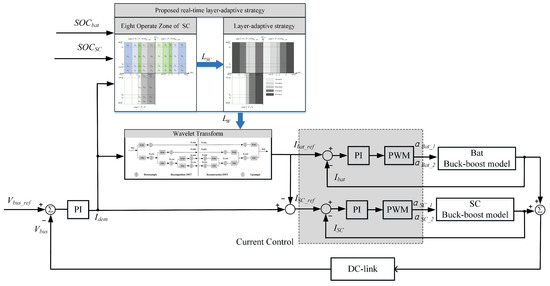
Figure 3.
The proposed energy management system. The proposed strategy obtains the number of layers of wavelet transform and the bottom closed-loop control circuits track the reference current of batteries and supercapacitors.
In this paper, a real-time layer-adaptive wavelet transform strategy is proposed. The wavelet transform is a signal process method that has proven its usefulness in a variety of applications [24]. Wavelet transform can extract characteristics of the transient signal and sharp changes in the load profile [25]. Therefore, wavelet transform is used in this paper to decouple the high-frequency component and the low-frequency component of the load power. As shown in Figure 4, the different frequency components can be achieved by multi-layer filtering. Haar wavelet transform is one of the simplest transformations in wavelet transform. The mother wavelet is Haar wavelet, which is a set of functions composed of a set of piecewise constant functions [26], as shown in Equation (16).
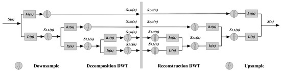
Figure 4.
A schematic diagram of the decomposition and reconstruction process of the three-layer wavelet transform.
The discrete wavelet transform (DWT) is used to decompose a discretized signal into different resolution layers. The DWT can be expressed as follows:
where represents the scale parameter. u represents the position parameter. Wavelet coefficients W is a function of and u. The wavelet with different time-frequency width can be obtained by adjusting the scale parameter and position parameter u to match any position of the original signal to achieve the purpose of time-frequency localization analysis of the signal.
As shown in Figure 4, the frequency in the frequency part obtained by different layers of decomposition is different. The higher the layers of decomposition, the more power included in the high frequency portion. Supercapacitors as the peak power buffer unit have limited energy, so the number of decomposition layers is critical to the SOC of supercapacitors. This proposed strategy firstly compares the current and the SOC of batteries and supercapacitors under the wavelet transform of different decomposition layers on the driving cycle LA92.
3.1. Decomposition Layers for the Wavelet Transform
As shown in Figure 5, when the wavelet transform of different layers is used, the SOC of batteries does not change significantly, while the SOC of supercapacitors has a significant difference. As the number of decomposition layers becomes higher and higher, the SOC of supercapacitors decreases faster, and the current of batteries also becomes smaller at the moment of the transient. Therefore, the higher the number of decomposition layers, the better the battery life, but there is an increase in the SOC consumption of the supercapacitors. Moreover, In order to maintain the SOC of the supercapacitors to cope with future instantaneous power, it makes sense to use different decomposition layers of wavelet transform. The SOC operation zone of supercapacitors is analyzed in the following section.
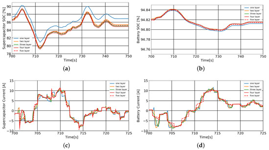
Figure 5.
The results of the wavelet transform of 1–5 layers are performed on the driving cycle LA92. (a) The state of charge (SOC) profiles of the batteries; (b) the SOC profiles of the supercapacitors; (c) the current profiles of the batteries; (d) the current profiles of the supercapacitors.
3.2. Operation Zones of Supercapacitors
The SOC of supercapacitors determines the amount of power they can supply to the load or absorb from the regenerative braking condition. As the peak energy buffer in the hybrid energy management system, supercapacitors should be fully utilized to ensure that supercapacitors respond quickly to power peaks during acceleration or absorb feedback energy in the braking condition. Therefore, the SOC of supercapacitors should always be kept within a preset range so that they can both provide high-frequency energy or absorb energy from regenerative braking at any moment. When the SOC of supercapacitors falls below this range, it should be charged by batteries or the load. When that goes out of range, it needs to be discharged to the preset range.
To keep the SOC of the supercapacitors within the most suitable range and maximize the SOC of the batteries, the SOCs of the supercapacitors and batteries are first analyzed in a two-dimensional coordinate system as shown in Figure 6. The horizontal axis represents the SOC range of the supercapacitors and the vertical axis represents the SOC range of the batteries. SOC represents the discharge capacity in the positive half-axis and the charge capacity in the negative half-axis. and P denote the maximum current of batteries and the load power demand, respectively. According to the rule-based method, the load demand is divided into three cases, namely , , and . The operation zones of supercapacitors was analyzed under these three specific load power demand conditions.
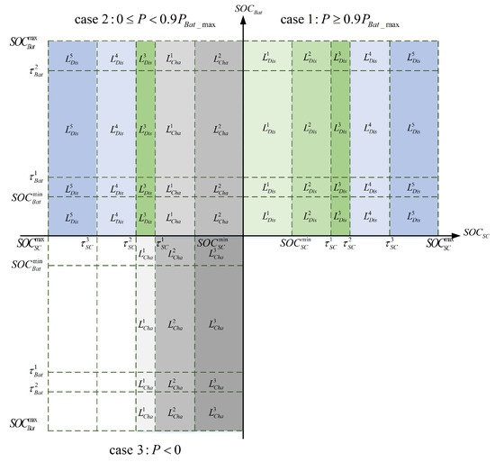
Figure 6.
The SOC combination of batteries and supercapacitors under three load demands, and the operation zone of supercapacitors is divided into eight cases.
The specific values of the nine thresholds , , , , , , , , and for the batteries and supercapacitors in Figure 6 are shown in Table 2. As mentioned in the previous section, the minimum values for the batteries and supercapacitors are 20% and 25%, respectively. The supercapacitor acts as the peak power buffer unit, so its stored energy should be maintained at about half of full power. Therefore, its SOC preset range is 45% to 55% [21]. In most cases, the SOC of batteries is within the two intermediate thresholds, namely and .
Table 2.
The threshold values of the SOCs of batteries and supercapacitors.
3.2.1.
According to Table 2, the SOC combination of batteries and supercapacitors is divided into 20 cases in the first quadrant. Since the load power P is greater than , both batteries and supercapacitors should provide power to the load as much as possible. Therefore, the operation zones of supercapacitors is divided into five power supply situations according to the SOC of supercapacitors, and the power supply capability from the strong to the weak is , , , , and , wherein the power supply capability of the has the highest discharge capability.
3.2.2.
Since in the second quadrant, it is considered that batteries need to supply power to supercapacitors and the load at the same time. Due to the role of supercapacitors as the peak power buffer unit, the SOC of supercapacitors should be maintained in the range [, ]. Therefore, when the SOC of supercapacitors is less than 45%, batteries supply both the load and supercapacitors for future charging and discharging. At this point, there are two cases of operation zones for supercapacitors, and , respectively, and the charging power depends on the batteries and the load. When the SOC of supercapacitors is higher than , supercapacitors and batteries work together to supply the load, and supercapacitors have three kinds of operation zones, namely, , and .
3.2.3.
In the third quadrant, the electric vehicle is in the regenerative braking condition, and the hybrid energy system needs to absorb regenerative energy. The operation zone of supercapacitors is divided into three cases: , , and , in which has the highest charge capability.
Therefore, the operation zone of supercapacitors is divided into eight cases as shown in Figure 6, namely, . Cases , , , , represent the discharge levels of supercapacitors, and cases , , represent the charging levels of supercapacitors.
3.3. Adaptive Determination of the Wavelet Transform with Different Decomposition Layer
In the previous subsection, the operation zones of supercapacitors were divided into eight cases. Combined with the frequency domain distribution of historical power demand of the load, the specific decomposition layer of the load power demand was analyzed. Obviously, different operation zones of supercapacitors correspond to the wavelet transform with different decomposition layers.
It is worth noting that the high-frequency components of signals obtained by the wavelet transform of different frequencies are different even with the same number of decomposition layers. The high-frequency components and low-frequency components obtained by the wavelet transform vary with different driving cycles. Therefore, the use of the wavelet transform has good scalability to different driving cycles.
According to the analysis of the 1–5 layer wavelet transform in Section 3.1, the wavelet transform of different decomposition layers corresponding to the operation zones of supercapacitors under three load power demand conditions is shown in Figure 7. The analysis is as follows.
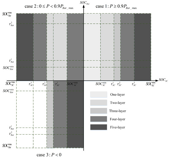
Figure 7.
The correspondence between the number of decomposition layers of wavelet transform and the operation zone of supercapacitors.
3.3.1.
In this case, the operation zones of supercapacitors are , , , , and . When = , the energy of supercapacitors is extremely low, hence the power allocated to supercapacitors should be as low as possible. The high frequency portion should contain as high a frequency as possible and as little energy as possible, thus performing a one-layer decomposition. When = , the supercapacitor is almost fully charged. In order to maintain supercapacitors as the peak power buffer unit, supercapacitors should be consumed as much as possible to the preset SOC range [, ].Therefore, the power allocated to supercapacitors should be as much as possible. The high-frequency part should contain a certain amount of energy, so a five-layer decomposition is performed. Therefore, the operation zones , , , , and correspond to the wavelet transform of the 1–5 decomposition layer, respectively.
3.3.2.
When , the operation zones are , , and , and the corresponding wavelet transform are five-layer, four-layer, and three-layer decomposition, respectively. When , the operation zones of supercapacitors are and . At this time, no wavelet conversion is performed, and supercapacitors are charged by batteries. The power of batteries transferred to supercapacitors is calculated as follows:
The power provided by batteries is the sum of the supercapacitors and the load.
3.3.3.
In the case of braking conditions, supercapacitors should absorb as much regenerative energy as possible. The operation zones of supercapacitors , , and correspond to the wavelet transform of three-layer, four-layer, and five-layer decomposition, respectively.
The layers of wavelet decomposition depend on the SOCs of the energy sources and the current load power demand. After the wavelet decomposition of different layers, the high-frequency component and low-frequency component in the power demand is decomposed, in which the low-frequency component is used as the reference current of the batteries, and the high-frequency component is used as the reference current of the supercapacitors. This strategy achieves a real-time adaptive-layer wavelet transform energy distribution strategy and effectively protects batteries while making full use of supercapacitors. In addition, the computational cost and time consumption of the adaptive-layer wavelet transform strategy is lower than using only a five-layer decomposition of wavelet transform.
4. Discussion
A dedicated scaled-down HESS experimental platform was used to validate the system described in Figure 1 and the effectiveness of the proposed strategy shown in Figure 8 using driving cycles LA92 and NYCC.
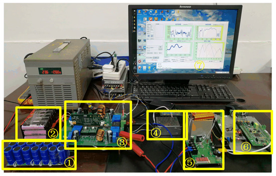
Figure 8.
An HESS physical experimental testbed. The modules are as follows: (1) Supercapacitors, (2) Batteries, (3) Two buck-boost converters, (4) Controllable constant current source, (5) Controllable constant current load, (6) MCU STM32F407, and (7) PC software-Driving cycle.
4.1. Setup of the Driving Environment
The battery pack is configured as four serial and five parallel connections with a commercial battery cell SAMSUNG ICR1865026H_M (2.6 Ah). The supercapacitor pack is configured as seven serial and two parallel connections with a Maxwell100F supercapacitor cell. The sample time applied during the experimental setup is 0.01 s [7]. In the experiment setup, we set the bus reference voltage to 24 V based on the sizing configuration of batteries and supercapacitors. The load power of the driving cycle was scaled down in an equal proportion of 150. It is worth noting that the frequency of the driving cycle provided by U.S. EPA is 1 Hz, which is too small to generate a smooth power profile. Therefore, before the load power was transmitted from the PC software to the MCUSTM32F407 through RS232, the driving cycle was interpolated to 100 Hz with three-spline interpolation.
The Air Resources Board LA92 Dynamometer Driving Schedule and the New York City Cycle (NYCC) selected in this paper are both from the US Environmental Protection Agency, as shown in Figure 9. The NYCC features low-speed stop-and-go traffic conditions, while the driving cycle LA92 has a higher top speed, a higher average speed, and a higher maximum rate of acceleration. These two driving cycles represent different road conditions with rich start, brake, acceleration, high-speed, and low-speed conditions. To better analyze the proposed strategy under a hybrid energy source scenario, a specific section of driving cycles was selected to contain the typical peak power demand in the cycle, i.e., [0–500], as presented in Figure 9a,b. The experimental results are shown in Figure 10 and Figure 11. The changes in current, voltage, and the SOC of the batteries and supercapacitors in the conventional method and the proposed method were analyzed and compared in the partial sections of driving cycles LA92 and NYCC.
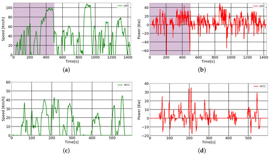
Figure 9.
The velocity profiles and power profiles of representative standard driving cycles LA92 dynamometer driving schedule (LA92) and the New York City Cycle (NYCC). (a) The speed profile of LA92; (b) the power profile of LA92; (c) the speed profile of NYCC; (d) the power profile of NYCC.
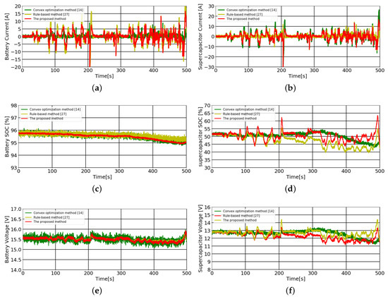
Figure 10.
The proposed method, the real-time frequency-based method [27], and the off-line optimization method [14] on the LA92 dynamometer driving schedule. (a) Current of battery profiles; (b) Current of supercapacitors profiles; (c) SOC of battery profiles; (d) SOC of supercapacitors profiles; (e) Voltage of battery profiles; (f) Voltage of battery profiles.
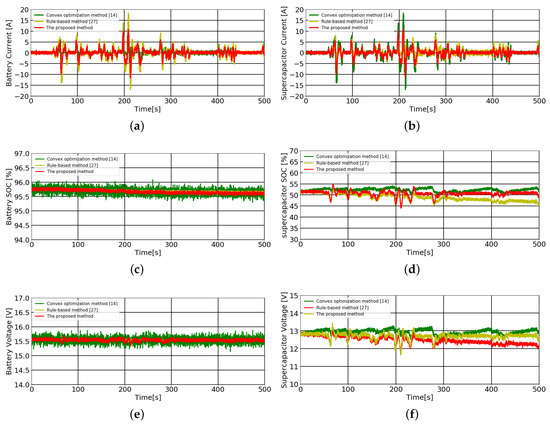
Figure 11.
The proposed method, the real-time frequency-based method [27], and the off-line optimization method [14] on the NYCC dynamometer driving schedule. (a) Current of battery profiles; (b) Current of supercapacitors profiles; (c) SOC of battery profiles; (d) SOC of supercapacitors profiles; (e) Voltage of battery profiles; (f) Voltage of battery profiles.
4.2. Results and Analysis
To verify the performance of the proposed method, a real-time frequency-based method [27] and an off-line optimization method [14] were compared with the proposed method on the driving cycle LA92 and the NYCC, respectively. As shown in Figure 10, the current, voltage, and SOC of the batteries and supercapacitors were compared using the three methods on the driving cycle LA92. Figure 11 depicts the performance of the three methods on the driving cycle NYCC for frequent shut-down and start-up conditions.
It can be seen in Figure 10a, among the three methods, the off-line optimization method obtains the minimum current, the frequency of the current obtained by the proposed method is the lowest, and the battery current of the real-time frequency-based method is the largest. In the proposed method, batteries provide less current and more gradual fluctuations at the peak of the load demand than the real-time frequency-based method. According to the current of supercapacitors in Figure 10b, the current of supercapacitors using the off-line optimization method is the largest. The supercapacitor current distributed by the proposed method is close to 0 where the load demand changes more smoothly, and supercapacitors bear more high-frequency components in the instantaneous change of the load demand than does the real-time frequency-based method. Obviously, supercapacitors act as the peak power buffer unit. When the load demand changes gently, it is mainly powered by batteries. The hybrid energy system is able to prolong the battery lifetime by filtering the high-frequency power demand into the supercapacitor. The waveform of the current assigned to supercapacitors in the proposed strategy is sharper and more frequent. As shown in Figure 10d,f, it can be seen that supercapacitors of the real-time frequency-based method have the fastest SOC and voltage drop. The SOC of the proposed method and the off-line optimization method can be maintained between 45% and 55%. Hence, the proposed method in this paper and the off-line optimization method are both more reasonable and sufficient for the use of supercapacitors, thus more effectively protecting batteries. In general, the proposed method performs better than the real-time frequency-based method, and is close to the performance achieved by the off-line optimization method.
Figure 11 shows the performance of three methods on the driving cycle NYCC in frequent shut-down and start-up conditions. As shown in Figure 11a,b, the batteries of the proposed method and the off-line optimization method have smaller currents, while the supercapacitors have larger currents, which is more conducive to protecting the battery and making full use of the supercapacitor. As shown in Figure 11d,f, the SOC of supercapacitors of the proposed method and the off-line optimization method are stable within the range 45–55%, while the SOC and voltage of supercapacitors using the real-time frequency-based method are slowly decreasing. In the low-speed case of the NYCC, supercapacitors are often used for start–stop and acceleration/deceleration, so it is necessary to keep the SOC of supercapacitors stable within the range of 45–55%. In this way, supercapacitors can absorb the regenerative energy at any time and can provide the instantaneous high-frequency power in the load, which can effectively protect batteries. In general, in the case of meeting the load demand, the off-line optimization method distributes less current to batteries, and supercapacitors have the largest current, which is the optimal energy distribution between batteries and supercapacitors, but the time and calculation costs are high and can only be used in off-line cases. The proposed method in this paper is better than the real-time frequency-based method in the distribution of batteries current, the utilization of supercapacitors, and the stability of the SOC of supercapacitors. Furthermore, the proposed method realizes the energy distribution in real time.
5. Conclusions
We proposed and experimentally verified a real-time layer-adaptive wavelet transform strategy for a hybrid battery–supercapacitor system in this paper. For the effect of wavelet transform with different decomposition layers on the reducing rate of supercapacitors SOC, the operation zones of supercapacitors are divided firstly according to the SOCs of batteries and supercapacitors and the load demand, and the number of decomposition layers is then adaptively obtained under the role of supercapacitors as the peak power buffer unit. Wavelet decomposition is then performed to separate the reference currents of batteries and supercapacitors separately. The experimental results show that batteries and supercapacitors are properly supplied in a specified range by analyzing the SOC of batteries and supercapacitors by a rule-based method and using a specific number of decomposition layers. Batteries mainly meet the part of the power demand that changes slowly, and supercapacitors quickly respond to the probability of abrupt changes. The advantage of our proposed method is to consider the SOC of supercapacitors for specific decomposition operations under wavelet transform. The calculation is simple, and a real-time layer-adaptive wavelet transform for power distribution of HESS is realized while effectively protecting batteries. Future work will focus on optimizing the division of load condition and on the SOC thresholds of batteries and supercapacitors according to other driving cycles using intelligent methods such as genetic algorithms and particle swarm optimization. Considering the simplest Haar function adopted in this paper, different wavelet functions will be investigated for various driving cycles with different characteristics, and will be verified by experiments in the future.
Author Contributions
Data curation, H.L. and Y.W.; Formal analysis, R.W.; Methodology, R.W.; Project administration, Z.H.; Resources, Y.Z.; Supervision, J.P.; Writing—original draft, R.W; Writing—review & editing, H.L.
Funding
This research was funded by the National Natural Science Foundation of China, grant numbers 61772558, 61803394, 61873353 and 61672537.
Conflicts of Interest
The authors declare no conflict of interest.
Abbreviations
The following abbreviations are used in this manuscript:
| HESS | hybrid energy storage system |
| EV | electric vehicle |
| SOC | state of charge |
| WT | wavelet transform |
| NYCC | The New York City Cycle |
| LA92 | The Air Resources Board LA92 Dynamometer Driving Schedule |
References
- Morais, H.; Sousa, T.; Vale, Z.; Faria, P. Evaluation of the electric vehicle impact in the power demand curve in a smart grid environment. Energy Convers. Manag. 2014, 82, 268–282. [Google Scholar] [CrossRef]
- Sousa, T.; Morais, H.; Pinto, T.; Vale, Z. Energy resource management under the influence of the weekend transition considering an intensive use of electric vehicles. In Proceedings of the 2015 Clemson University Power Systems Conference (PSC), Clemson, SC, USA, 10–13 March 2015; pp. 1–16. [Google Scholar]
- Caetano, N.S.; Mata, T.M.; Martins, A.A.; Felgueiras, M.C. New trends in energy production and utilization. Energy Procedia 2007, 107, 7–14. [Google Scholar] [CrossRef]
- Li, H.; Peng, J.; He, J.; Zhou, R.; Huang, Z.; Pan, J. A cooperative charging protocol for onboard supercapacitors of catenary-free trams. IEEE Trans. Control Syst. Technol. 2018, 26, 1219–1232. [Google Scholar] [CrossRef]
- Li, L.; Huang, Z.; Li, H.; Peng, J. A rapid cell voltage balancing scheme for supercapacitor based energy storage systems for urban rail vehicless. Electr. Power Syst. Res. 2017, 142, 329–340. [Google Scholar] [CrossRef]
- Karden, E.; Ploumen, S.; Fricke, B.; Miller, T.; Snyder, K. Energy storage devices for future hybrid electric vehicles. J. Power Sources 2007, 168, 2–11. [Google Scholar] [CrossRef]
- Zhou, Y.; Huang, Z.; Liao, H.; Li, H.; Jiao, Y.; Jun, P. An efficient reference modulation based control strategy for active hybrid energy management of EVs. In Proceedings of the IEEE 2018 Energy Conversion Congress and Exposition (ECCE) Portland, Oregon, USA, Portland, OR, USA, 23–27 September 2018. [Google Scholar]
- Zhou, Y.; Huang, Z.; Li, H.; Peng, J.; Liu, W.; Liao, H. A Generalized Extended State Observer for Supercapacitor State of Energy Estimation with Online Identified Model. IEEE Access 2018, 6, 27706–27716. [Google Scholar] [CrossRef]
- Song, Z.; Li, J.; Han, X.; Xu, L.; Lu, L.; Ouyang, M.; Hofmann, H. Multi-objective optimization of a semi-active battery/supercapacitor energy storage system for electric vehicles. Appl. Energy 2014, 135, 212–224. [Google Scholar] [CrossRef]
- Liu, H.; Wang, Z.; Cheng, J.; Maly, D. Improvement on the cold cranking capacity of commercial vehicle by using supercapacitor and lead-acid battery hybrid. IEEE Trans. Veh. Technol. 2009, 58, 1097–1105. [Google Scholar]
- He, H.; Xiong, R.; Zhao, K.; Liu, Z. Energy management strategy research on a hybrid power system by hardware-in-loop experiments. Appl. Energy 2013, 112, 1311–1317. [Google Scholar] [CrossRef]
- Trovão, J.P.; Pereirinha, P.G.; Jorge, H.M.; Antunes, C.H. A multi-level energy management system for multi-source electric vehicles-an integrated rule-based meta-heuristic approach. Appl. Energy 2013, 105, 304–318. [Google Scholar] [CrossRef]
- Wang, H.; Huang, Y.; Khajepour, A. Cyber-Physical Control for Energy Management of Off-road Vehicles with Hybrid Energy Storage Systems. IEEE/ASME Trans. Mechatron. 2018, 23, 2609–2618. [Google Scholar] [CrossRef]
- Huang, Y.; Wang, H.; Khajepour, A.; Li, B.; Ji, J.; Zhao, K.; Hu, C. A review of power management strategies and component sizing methods for hybrid vehicles. Renew. Sustain. Energy Rev. 2018, 96, 132–144. [Google Scholar] [CrossRef]
- Choi, M.E.; Kim, S.W.; Seo, S.W. Energy Management Optimization in a Battery/Supercapacitor Hybrid Energy Storage System. IEEE Trans. Smart Grid 2012, 3, 463–472. [Google Scholar] [CrossRef]
- Herrera, V.I.; Gaztanaga, H.; Milo, A.; Saez-de-Ibarra, A.; Etxeberria-Otadui, I.; Nieva, T. Optimal Energy Management and Sizing of a Battery–Supercapacitor-Based Light Rail Vehicle With a Multiobjective Approach. IEEE Trans. Ind. Appl. 2016, 52, 3367–3377. [Google Scholar] [CrossRef]
- Florescu, A.; Bacha, S.; Munteanu, I.; Bratcu, A.I.; Rumeau, A. Adaptive frequency-separation-based energy management system for electric vehicles. J. Power Sources 2015, 280, 410–421. [Google Scholar] [CrossRef]
- Li, Q.; Chen, W.; Liu, Z.; Li, M.; Ma, L. Development of energy management system based on a power sharing strategy for a fuel cell-battery-supercapacitor hybrid tramway. J. Power Sources 2015, 279, 267–280. [Google Scholar] [CrossRef]
- Mao, P.L.; Aggarwal, R.K. A novel approach to the classification of the transient phenomena in power transformers using combined wavelet transform and neural network. IEEE Trans. Power Deliv. 2001, 16, 654–660. [Google Scholar] [CrossRef]
- Liang, Z.; Xin, Z.; Yi, T.; Xinn, Z. Intelligent energy management for parallel HEV based on driving cycle identification using SVM. In Proceedings of the International Workshop on IK Formation Security and Application, Qingdao, China, 21–22 November 2009; pp. 457–460. [Google Scholar]
- Herrera, V.I.; Saez-de-Ibarra, A.; Milo, A.; Gaztañaga, H.; Camblong, H. Optimal energy management of a hybrid electric bus with a battery-supercapacitor storage system using genetic algorithm. In Proceedings of the Electrical Systems for Aircraft, Railway, Ship Propulsion and Road Vehicles (ESARS), Aachen, Germany, 3–5 March 2015; pp. 1–6. [Google Scholar]
- Song, Z.; Hofmann, H.; Li, J.; Han, X.; Ouyang, M. Optimization for a hybrid energy storage system in electric vehicles using dynamic programing approach. Appl. Energy 2015, 139, 151–162. [Google Scholar] [CrossRef]
- Elbert, P.; Gisler, H.J. Capacitors vs. Batteries in a serial hybrid electric bus. IFAC Proc. 2010, 43, 252–257. [Google Scholar] [CrossRef]
- Erdinc, O.; Vural, B.; Uzunoglu, M. A wavelet-fuzzy logic based energy management strategy for a fuel cell/battery/ultra-capacitor hybrid vehicular power system. J. Power Sources 2009, 194, 369–380. [Google Scholar] [CrossRef]
- Erdinc, O.; Vural, B.; Uzunoglu, M.; Ates, Y. Modeling and analysis of an FC/UC hybrid vehicular power system using a wavelet-fuzzy logic based load sharing and control algorithm. Int. J. Hydrogen Energy 2009, 34, 5223–5233. [Google Scholar] [CrossRef]
- Zhang, X.; Mi, C.C.; Masrur, A.; Daniszewski, D. Wavelet-transform-based power management of hybrid vehicles with multiple on-board energy sources including fuel cell, battery and ultracapacitor. J. Power Sources 2008, 185, 1533–1543. [Google Scholar] [CrossRef]
- Manandhar, U.; Tummuru, R.; Kumar, S.; Ukil, A.; Beng, G.H. Validation of faster joint control strategy for battery and supercapacitor based energy storage system. IEEE Trans. Ind. Electron. 2017, 65, 3286–3295. [Google Scholar] [CrossRef]


© 2019 by the authors. Licensee MDPI, Basel, Switzerland. This article is an open access article distributed under the terms and conditions of the Creative Commons Attribution (CC BY) license (http://creativecommons.org/licenses/by/4.0/).