Abstract
In order to reduce large deformation failure occurrences in non-pillar longwall mining entries due to roof weighting behaviors, a case study in Halagou coal mine was conducted on optimization and control techniques for entry stability in non-pillar longwall mining. The Universal Discrete Element Code (UDEC) modeling was adopted to study entry stability in non-pillar mining, and the characteristics of deformation and stress and crack propagation were revealed. The large deformation transmission between the entry-immediate roof and the gob-immediate roof could be eliminated by optimizing the entry roof structure through a directional roof-cutting method. The localized tensile stresses generated in the entry-surrounding rock caused the generation of coalescent macroscopic fractures, which resulted in the instability of the entry. The tensile stress state could be inhibited by an active flexible support system through enhancing the confining pressure on the surrounding rock. Serious rotation subsidence occurs in the entry roof due to periodic weighting of the main roof, which could be greatly reduced by a passive rigid support pattern. The numerical and field test results both showed that the roof weighting pressure was offloaded by the technique and that the deformation of the entry surrounding the rock in non-pillar mining was quite small. Thus, the technique can effectively ensure the stability of the gob-side entry, which can provide references for entry stability control in non-pillar longwall mining.
1. Introduction
Coal is one of the most important physical resources of the global economy and for the development of global society, accounting for 30% of the world’s total energy consumption [1]. Underground mining accounts for 60% of the world’s coal production. Underground coal mining mostly adopts the longwall mining method. In this mining method, transportation and ventilation entries need to be excavated on both sides of the mining panel, and a coal pillar needs to be retained between two adjacent mining panels to guarantee the stability of the entry into the next mining panel. However, the size of the abandoned coal pillars is usually large. The loss of the residual coal pillars causes a huge waste of coal resources and economic loss, accounting for approximately 10% to 30% of the total coal production [2].
Non-pillar longwall mining was developed and implemented in the 1930s [3]. Non-pillar coal mining is also known as gob-side entry retaining, which has gradually become a popular and effective way to improve resource recovery. In this method, the entry is artificially retained by constructing a filling wall along the gob-side of the entry, which can be implemented for transportation and ventilation entry deployment in the next working face. This method can effectively decrease coal resource waste and reduce roadway drivage ratios [4]. However, large deformation failure or collapse accidents frequently occur in gob-side entries during the working face extraction, accounting for 76% of mining accidents [5]. These accidents lead to serious personnel casualties, economic loss, and a delay in mining activities. The root cause of these accidents is that roof-weighting behavior is violent during working face extraction [6]. Mining-induced stress impacts the entry-surrounding rock and the filling wall through the integral roof force transfer structure [7], but the capability of the filling wall is often too weak to resist mining-induced stress, which induces large deformation failure in the entry-surrounding rock and the filling wall. Furthermore, the cost of the filling materials is expensive, and the method is time-consuming [2]. These reasons have severely restricted the popularization and application of the non-pillar longwall mining method. Thus, it is necessary to find a universally applicable and economical method to maintain the stability of the gob-side entry in non-pillar longwall mining.
Therefore, for the purpose of maintaining the stability of the entry in non-pillar longwall mining, we first present a roof-cutting method to optimize the entry roof structure in non-pillar longwall mining. Then, the deformation mechanism of the gob-side entry undergoing roof cutting is systematically studied by using numerical modeling. Subsequently, the stability control principles of entry stability in non-pillar longwall mining are proposed, and relevant support techniques are made. Finally, numerical modeling and underground tests were conducted to evaluate the effect of the entry stability control techniques.
2. Engineering Geological Conditions
2.1. Mine Overview
Halagou coal mine is located in Yulin City, Shanxi Province, China (Figure 1a). The depth of longwall panel 12201 varies between 60 and 100 m. The layout of the longwall mining panel is shown in Figure 1b. The detailed stratum column of the surrounding rocks is described in Figure 2. The immediate roof of the panel is composed of siltstone, coal, and fine sandstone. The main roof of the panel is composed of fine sandstone and siltstone. The floor of the panel is composed of fine siltstone and fine sandstone. The mining coal seam is #1 coal, with a height of 1.9 m.
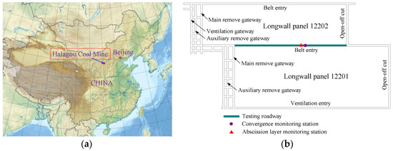
Figure 1.
(a) The location of the Halagou coal mine, Shanxi, China; (b) Plane layout of the mining panel.
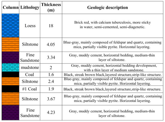
Figure 2.
Stratum column and geological description of the mining panel.
2.2. Rock Mass Parameters
Through sampling experiments with the International Society for Rock Mechanics (ISRM) recommended standard on rock samples obtained from the strata in the mining panel [8], the related physico-mechanical parameters of the intact rock were obtained, as shown in Table 1. The strength of the rock mass was reduced due to the discontinuity (such as joints, cracks, bedding). Thus, it was essential to discount the intact rock parameters. The intact rock strength properties were multiplied by a scale factor of 0.58 to obtain the rock mass strength properties [9]. The elastic modulus in GPa was 0.31 times the rock mass strength value in MPa [10]. The tensile strength of the rock masses was reasonably estimated to be 1/10 of the compressive strength [11].

Table 1.
Intact rock and calculated rock mass physico-mechanical parameters.
3. Optimization Principles of Entry Stability in Non-Pillar Mining
The optimization principle of the gob-side entry stability was to construct a cutting structural plane in the gob-side immediate roof. The movement of the entry roof was constrained by the supporting structure. The gob-side immediate roof fractured and caved along the cutting structural plane after working face mining, as shown in Figure 3. The caved immediate roof formed a new entry rib. The negative impact of the gob-immediate roof caving on the retained entry stability was eliminated by the roof-cutting method. The adverse effect of the periodic weighting-induced main roof rotation subsidence on the entry-surrounding rock was inhibited by the supporting structure.
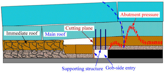
Figure 3.
Structural model cross-section of non-pillar mining.
Roof cutting is considered to make the immediate roof fall smoothly. It is necessary to let the cutting fracture reach the boundary between the immediate roof strata and the main roof strata. The immediate roof was composed of siltstone, coal, and mudstone, with a total height of 6 m, and thus the roof-cutting height was 6 m.
The low-strength coal and mudstone in the immediate roof were easy to cave along the cutting plane. The high-strength siltstone in the immediate roof was difficult to cave along the cutting plane. The smooth caving of the siltstone required the sliding force on the cutting plane to be greater than the frictional resistance. Frictional resistance can be decreased by increasing the cutting angle in the vertical direction [12]. The roof cutting angle could be calculated by the following formulas [13]:
where φ is the frictional angle of the siltstone, φ = 17°; h is the thickness of the siltstone, h = 2.4 m; ΔS is the subsidence of the siltstone, ΔS = 1.9 m; L is the limit span of the siltstone, L = 8 m. Based on the above equation and its relevant parameters, the cutting angle was calculated to be 9.87°. Considering the field construction condition, the cutting angle was inclined by 10° toward the gob side.
4. Numerical Modeling of the Entry Undergoing Roof Cutting
4.1. Model Establishment
Numerical modeling was conducted to investigate the deformation mechanism of the gob-side entry undergoing roof cutting. The Universal Discrete Element Code (UDEC) code is intrinsically capable of modeling large-scale movement, rotation, and complete detachment of the rock strata: Consequently, it could explicitly reproduce the fractured zone and the caved zone, and it could accurately reveal the post-failure area of the rib spalling and roof collapse [14,15]. Therefore, UDEC software was employed to study the deformation mechanism of the gob-side entry undergoing roof cutting. In the discontinuum UDEC code, the computational domain was discretized into bonded blocks by intersecting discontinuities at their boundaries, and the interface between these blocks was viewed as a contact [16].
Based on the geomechanical condition of the 12201 longwall panel, a discrete element model of non-pillar mining was established, as shown in Figure 4. The model was 150 m (width) × 41.6 m (height), and it simulated the cross-section of the longwall panel. The cross-section involved the 12201 longwall face, the belt entry, and the ventilation entry. A 30-m-wide region at both sides of the model was preserved to avoid the boundary effect. According to the measured in situ stress with the stress relief method [17], a horizontal stress of 1.5 MPa and a vertical stress of 3 MPa were applied to the model. The horizontal displacement of the lateral boundaries and the vertical displacement of the bottom boundaries were constrained. A vertical stress of 3 MPa, equivalent to the overburden weight, was applied to the upper boundary of the model. In view of the fracturing and caving behaviors of the rock stratum being mainly dominated by discontinuities in the rock mass, an elastic model and a coulomb slip model were employed for intact rock blocks and the contact, respectively. The initiation, propagation, and coalescence process of the fractures could be directly represented by the sliding or the opening of the contact when the induced contact stress exceeded their tensile or shear strengths [18]. The area of interest around the roadway was discretized into triangular blocks for its unparalleled advantages in effectively simulating the crack evolution pattern [19], while the other strata were divided into rectangular blocks for their capability of simulating the movement of the rock strata. Pre-existing discontinuities, including bedding planes and cross joints, were incorporated into each rock stratum.
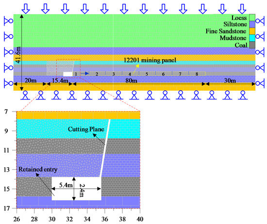
Figure 4.
Numerical model of non-pillar longwall mining.
For the triangular blocks in the coal seam and in the immediate roof, the average edge length was 0.25, which was sufficiently small to reveal the fracture development. For the remainder of the model, the rectangular blocks were progressively graded with increasing edge length (0.3 m × 0.2 m, 0.4 m × 0.24 m, 0.5 m × 0.25 m, 1.36 m × 0.68 m, 1.6 m × 0.8 m, 1.9 m × 0.95 m, 4 m × 2 m, and 4 m × 2.2 m) at a distance from the retained entry to avoid a sudden large increase in block size, which would have decreased modeling accuracy.
4.2. Calibrated Rock Mass Parameters
The physical and mechanical parameters of the rock blocks and contacts used in the UDEC model were calibrated against the rock mass parameters listed in Table 1. This was achieved by conducting a series of unconfined compression tests on the numerical specimens [19]. The calibrated specimens had identical mesh patterns and sizes to the non-pillar longwall mining model. The original rock mass parameters were first estimated based on the rock mass properties and then calibrated iteratively by numerical unconfined compression tests until the targeted Young’s modulus and compressive strength listed in Table 1 were attained, as shown in Figure 5. To ensure that the specimens were fully yielding and entering into the post-failure zone, the number of calculation steps was 104. A loading rate of 0.1 m/s was used in this paper [20]. The optimal axial stress–axial strain curves of the numerical tests are displayed in Figure 5. The calibrated optimal parameters of the UDEC model are illustrated in Table 2. The calibrated Young’s modulus value and the compressive strength value are listed in Table 3. It can be seen that the calibrated Young’s modulus value and the compressive strength value were approximately equal to the targeted value. Therefore, the rock mass parameters listed in Table 2 could be applied to the non-pillar longwall mining model.
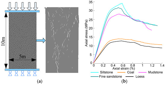
Figure 5.
Simulated unconfined compression tests and obtained optimal axial stress–axial strain curves: (a) Unconfined compression tests; (b) stress–axial strain curves.
Table 2.
Physical and mechanical parameters of rock mass used in the UDEC model.
Table 3.
Calibrated Young’s modulus value and the compressive strength value in the UDEC model.
4.3. Modeling Procedures
The model was first run to equilibrium to form an in situ stress field that was similar to the study site. Then, an entry with a 5.4 m × 2.4 m dimension was excavated. This was achieved by deleting the blocks within the entry cross-section and then gradually decreasing the stresses on the entry surface to realistically simulate the stress-releasing process caused by excavation. After the excavated entry reached a stable state, the cutting plane was constructed in the roof by deleting the relevant rock blocks, and panel 12201 was extracted. The extraction of the 12201 longwall face was divided into eight stages. Each stage involved a 10-m advance from right to left by deleting the blocks within the mining panel, and 30,000 time steps were run in each stage to completely release the mining-induced stresses. The simulation model is shown in Figure 4.
5. Numerical Modeling Results of the Entry Undergoing Roof Cutting
5.1. Deformation Character Analysis
Figure 6 displays the final displacement map in the surrounding rock. After mining of the #1 coal seam, the gob side-immediate roof first caved along the cutting plane. The consistent deformation between the entry-immediate roof and the gob-immediate roof was eliminated. However, serious rotation deformation occurred in the entry roof. The deformation degree gradually decreased from the gob side to the coal rib. Rib spalling occurred in the shallow surrounding rock, and there was no obvious floor heave. The monitored line, with a length of 10 m, was set in the roof and coal rib at a distance of 1.8 m, 3.6 m, and 5.4 m from the coal rib and 0.8 m, 1.3 m, and 1.8 m from the floor, as shown in Figure 7. The maximum roof subsidence was 477 mm, 596 mm, and 697 mm, respectively. The maximum convergence of the coal rib was 77 mm, 119 mm, and 87 mm, respectively. The dramatic change in the curves indicated a serious abscission layer and spalling generation in the entry-surrounding rock.
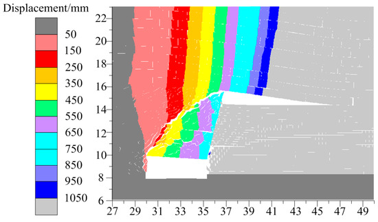
Figure 6.
Simulated displacement map in the entry-surrounding rock.
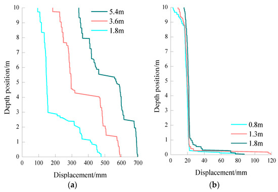
Figure 7.
Simulated displacement curve of the surrounding rock: (a) Roof; (b) coal rib.
5.2. Crack Evolution Analysis
The failure patterns of the gob-side entry are shown in Figure 8a. Heavy macroscopic fractures developed in the entry-surrounding rock. The fragmentation degree was gradually alleviated from the gob side to the coal rib. Coalescent macroscopic fractures caused instability in the entry-surrounding rock [21]. Figure 8b reveals the microcosmic crack evolution pattern of the gob-side entry. Microcosmic shear cracks were mainly generated in the deep coal rib. Microcosmic tensile cracks were generated in the entry roof and shallow coal rib. It can be seen that the evolution of microcosmic tensile cracks caused the generation of heavy macroscopic fractures in the entry-surrounding rock.
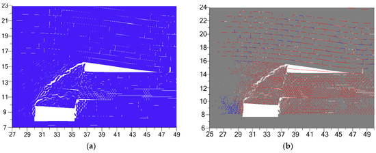
Figure 8.
Simulated failure patterns in the entry-surrounding rock: (a) Macroscopic fracture evolution; (b) microcosmic crack evolution. Tensile and shear cracks are marked by red and blue, respectively.
5.3. Stress Distribution Analysis
From the vertical stress map in Figure 9a, it can be seen that when the roof movement was stable, the entry-surrounding rock was all in the low stress area, and the high abutment pressure area was located in the interior of the coal rib, which exceeded the compressive strength of the coal rib and caused the generation of slight shear cracks. The peak value of the abutment pressure was 12.85 MPa, and the depth of the peak value from the coal rib was 3.39 m. A large tensile stress zone was generated in the immediate roof and coal rib. Tensile stresses dramatically caused the generation and propagation of tensile cracks [22]. A localized distribution map of tensile stress in the surrounding rock is shown in Figure 9b. It can be seen that the tensile stress zone had a similar range to the fractured zone in the entry-surrounding rock.
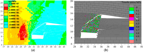
Figure 9.
Simulated stress distribution map in the entry-surrounding rock: (a) Vertical stress; (b) tensile stress.
5.4. Deformation Mechanism and Control Principles of the Gob-Side Entry
After mining of the #1 coal seam, serious rotation deformation occurred in the entry roof. The localized tensile stresses generated in the entry-surrounding rock led to heavy microscopic tensile cracks, which caused the generation of macroscopic fractures in the entry-surrounding rock. Coalescent macroscopic fractures caused the instability of the entry roof and the coal rib. The tensile stress state can be inhibited by increasing the residual tensile strength of the immediate roof and coal rib. This can be achieved by enhancing the confining pressure on the immediate roof and the coal rib [23]. An active flexible support pattern, such as bolts and cables, has proven to be an effective way to enhance the confining pressure by applying sufficient pre-stress on the support structure [24,25]. In addition, the immediate roof could be suspended and compressed into the main roof, which was more resistant to the abscission layer. The rotation deformation in the immediate roof could be alleviated by installing a rigid hydraulic support and I-steel in the entry to form a high-strength-bearing structure. When the movement of the main roof and the immediate roof became stable, the rigid hydraulic support in the entry could be removed.
6. Control Techniques of the Gob-Side Entry Undergoing Roof Cutting
6.1. Support Parameters
The design of the active flexible support parameters in the roadway is shown in Figure 10. The active flexible support scheme was composed of “bolt + cable + steel strip + mesh”, and six Φ 18 mm × 1800 mm threaded steel bolts were installed in the entry roof with a column spacing and row spacing of 900 mm × 1000 mm. Two Φ 20 mm × 1800 mm Fiber Reinforce Plastic(FRP) bolts were installed in the entry rib with plastic mesh. The column spacing and row spacing of the FRP bolts was 1050 mm × 1500 mm. The bolts in the corner were inclined at 10° angles. The pre-stress applied on the bolts was no less than 80 kN. The grid size of the plastic mesh was 40 mm × 40 mm. Three Φ 22 mm × 8000 mm cables were installed in the roof with a column spacing and row spacing of 2000 mm × 2000 mm. The cables were installed with a π-steel strip 4600 mm long × 140 mm wide × 8 mm thick. A list of Φ 22 mm × 8000 mm cables were installed in the roof along the cutting plane with column spacing of 2000 mm. The pre-stress applied on the cables was no less than 280 kN. The cables were installed with steel plates that were 150 mm long × 150 mm wide, a W-steel strip 4600 mm long × 230 wide × 4 mm thick, and steel mesh. The diameter of the steel mesh was Φ 6.5 mm, with a grid size of 100 mm × 100 mm. The passive rigid support scheme was composed of “hydraulic support + π-beam + I-steel + steel mesh”. Five hydraulic supports were installed with a 5000-mm-long π-beam in the entry cross-section. The column spacing of the hydraulic supports is shown in Figure 10. The row spacing of the hydraulic supports was 1000 mm. In addition, #11 I-steel and steel mesh were installed along the cutting plane, with a column spacing of 1000 mm.
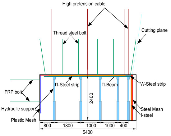
Figure 10.
Support scheme of the gob-side entry.
6.2. Establishment of the Model under a Supporting Condition
The discontinuum UDEC code was used to check the effect of the supporting scheme. The type and parameters of the blocks and the contact were consistent with the previous model. The modeling procedures of the model under a supporting condition were identical to the previous model. A cable element was used to simulate the bolt and cable, a support element was used to simulate the I-steel and hydraulic support, and a structure element was used to simulate the mesh, steel strip, and π-beam.
The parameters of each support element are illustrated in Table 4, Table 5 and Table 6. The supporting model is shown in Figure 11. The model was run to equilibrium to release mining-induced stress after the #1 coal seam was excavated. When the model was equalized, the hydraulic support and the π-beam were removed by the delete command. The model continued to run to final equilibrium.
Table 4.
Properties of the bolt and cable elements used in the UDEC.
Table 5.
Properties of the structure element in the UDEC.
Table 6.
Properties of the support element in the UDEC.
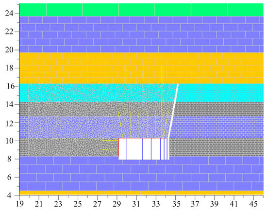
Figure 11.
Numerical model of the gob-side entry in a supporting condition.
6.3. Numerical Modeling Results of the Model under a Supporting Condition
The confining pressure applied by the active flexible support effectively inhibited the tensile stress state, as shown in Figure 12. Consequently, the growth and propagation degrees of the microscopic tensile cracks were reduced significantly (Figure 13). Meanwhile, only slight macroscopic fractures were generated in the immediate roof (Figure 14). The coalescent macroscopic fractures that caused instability in the entry roof and the coal rib disappeared.
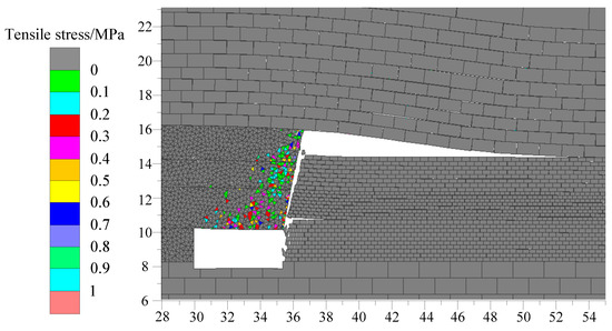
Figure 12.
Simulated localized tensile stress distribution map in the entry-surrounding rock in a supported condition.
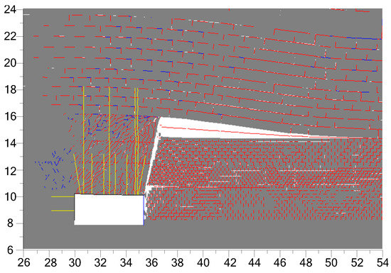
Figure 13.
Simulated microscopic crack evolution in the entry-surrounding rock in a supported condition.
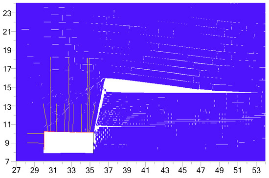
Figure 14.
Simulated failure patterns of the entry in a supported condition.
Figure 15 displays the final displacement map in the surrounding rock of the gob-side entry in a supported condition. The passive rigid support system significantly alleviated the rotation deformation in the immediate roof, and the deformation in the surrounding rock was still small after the hydraulic support and the π-beam were removed, which indicated that the main roof formed a stable voussoir beam structure. The same monitored lines that were described in Section 4.1 were set, as shown in Figure 16. The maximum roof subsidence in the supported condition was 61 mm, 97 mm, and 128 mm, respectively. The reduction rates were 87%, 84%, and 82%. The maximum convergence of the coal rib was 20 mm, 21 mm, and 16 mm, respectively. The reduction rates were 74%, 82%, and 82%. The deformation degree was enormously decreased. The dramatic change in the displacement curves became uniform.
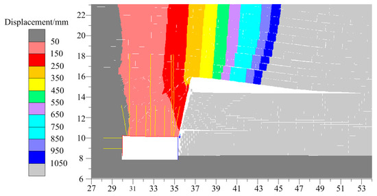
Figure 15.
Simulated displacement map of the entry-surrounding rock in a supported condition.
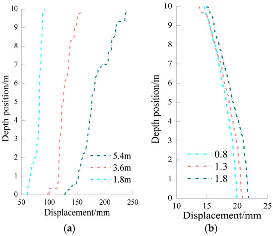
Figure 16.
Simulated displacement curves of the surrounding rock in a supported condition: (a) Roof; (b) rib.
7. Engineering Applications
7.1. The Technique of Entry Roof Cutting in Non-Pillar Mining
A field test was conducted in the 12201 transportation entry. A cutting plane with a height of 6 m and an angle of 10° was formed in the entry roof by bidirectional energy cumulative tension failure blasting technology. The principle of this technique is shown in Figure 17. First, blasting holes were drilled in the pre-split surrounding rock. Then, a cumulative device and explosive were employed to create a uniform compressive stress on the blast hole wall in non-predefined directions and form a cohesive energy flow that was transmitted in pre-split directions. The directional cohesive energy flow produced concentrated tensile stress, which caused the initiation and extension of directional tension failure in the roof-surrounding rock until it propagated into a coalescent fracture plane [26], as shown in Figure 18.
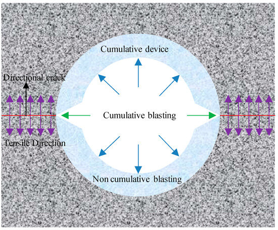
Figure 17.
Principles of the directional roof-cutting technique.
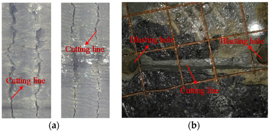
Figure 18.
Cumulative blasting effect: (a) The cutting plane in the immediate roof; (b) the cutting plane on the entry roof surface.
7.2. The Technique of Entry Support in Non-Pillar Mining
Before the mining of the working face, an active flexible support system was installed in the entry, as shown in Figure 19a. Before the cutting-immediate roof collapsed, a passive rigid support system was installed in the entry, as shown in Figure 19b. As the working face progressed, the immediate roof rock in the gob area gradually collapsed, the gob-side caved gangue gradually became compacted, and a gangue rib eventually formed, as shown in Figure 19a.
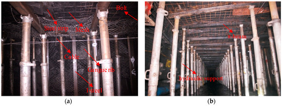
Figure 19.
Support system installation in the entry: (a) Active flexible support system; (b) passive rigid support system.
7.3. Effect of the Entry Stability Control
To verify the feasibility of the entry stability control techniques, the roof and floor convergence and the abscission layer in the immediate roof of the gob-side entry were monitored and analyzed. Monitoring stations were deployed along the gob-side entry. Additionally, real-time monitoring sensors were installed at each monitoring station for convergence and abscission layer data monitoring, as shown in Figure 20.
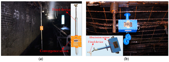
Figure 20.
Real-time monitoring equipment for entry deformation: (a) Abscission sensor; (b) convergence sensor.
The roof and floor convergence monitoring results are shown in Figure 21. The abscission layer monitoring results are shown in Figure 22. Due to the extraction of the coal seam, the immediate roof on the gob side started to cave along the cutting plane, the roof and floor convergence of the entry increased slowly, and there was no abscission layer with the face advance of 0–20 m, which indicated that the caving of the immediate roof in the gob had little impact on the stability of entry, due to the roof cutting. During the face advance of 20–35 m, the convergence curve and the abscission layer curve increased dramatically: This was caused by the fracture and rotation subsidence of the main roof due to periodic weighting of the mining face [27]. The deformation rate reduced significantly at a face advance of 35–60 m, which indicated that the main roof touched the caved gauges of the immediate roof in the gob and formed a stable voussoir beam structure. Furthermore, the caved gauges became compacted under the compression of the main roof. When the working face progress reached approximately 100 m, the convergence curve and the abscission layer curve stabilized at approximately 117 mm and 12 mm, respectively. At this stage, the hydraulic support and the π-beam were removed, as shown in Figure 23. After the hydraulic supports were removed, the roof and floor convergence and the abscission layer value slightly increased. When the working face progress reached approximately 115 m, the convergence curve and the abscission layer curve again stabilized at approximately 124 mm and 13 mm, respectively.
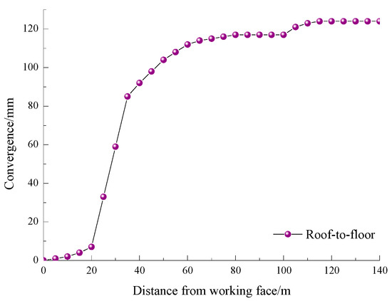
Figure 21.
Real-time monitoring curve of roof and floor convergence.
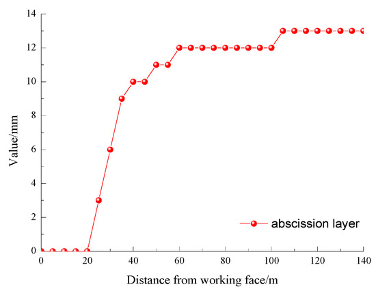
Figure 22.
Real-time monitoring curve of the abscission layer in the immediate roof.
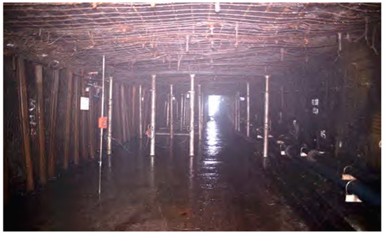
Figure 23.
Effect of the formed roadway after removing the hydraulic support and the π-beam.
The engineering test showed that the directional roof-cutting technique eliminated the impact of gob-immediate roof caving on the entry roof. Additionally, due to the active flexible support system and the passive rigid support system, the impact of the periodic weighting of the mining face on the entry roof was extremely weak. Consequently, the deformation rate and the scale of the roadway-surrounding rock were significantly reduced, which indicated that the stability control techniques were effective (as shown in Figure 23), the roadway was well-formed and the final size of the roadway section met the production requirements for the next panel, and the target of entry stability control in non-pillar mining was achieved.
8. Conclusion
In this paper, entry stability optimization and control techniques in non-pillar mining were studied, and numerical modeling and engineering tests were conducted. The main findings conclude as follows.
The numerical modeling of the entry stability in non-pillar mining showed that the large deformation transmission between the entry-immediate roof and the gob-immediate roof could be eliminated by roof cutting. However, the localized tensile stresses generated in the entry-surrounding rock caused the generation of coalescent macroscopic fractures, which led to the instability of the entry-surrounding rock. An active flexible support pattern could improve the tensile stress state by enhancing the confining pressure on the surrounding rock. A large rotational subsidence in the entry roof due to periodic weighting of the mining face could be significantly alleviated by a passive rigid support pattern.
Key techniques for entry stability control in non-pillar mining include the technique of directional roof cutting, an active flexible support system, and a passive rigid support system. The directional roof-cutting technique optimizes the movement characters of the gob-side roof structure, active flexible support improves the stress state of the surrounding rock, and passive rigid support inhibits large rotational deformation in the entry roof. The engineering applications of entry stability control techniques in non-pillar mining showed that the deformation rate and the degree of the entry-surrounding rock were quite small, which indicated that the stability control techniques are feasible. Thus, these techniques can effectively ensure entry stability in non-pillar mining, which can be widely applied to coal mines globally.
Author Contributions
X.Y. conceived the theme; E.W. designed and performed the numerical simulations. E.W. and H.L. designed and performed the field tests; X.M. and H.L. performed the laboratory experiments; G.Z. and R.H. provided theoretical and technical guidance; E.W. analyzed the data and wrote the paper.
Funding
This research was funded by the National Natural Science Foundation of China, grant number No. 41672347.
Conflicts of Interest
The authors declare no conflict of interest.
References
- Milici, R.C.; Flores, R.M.; Stricker, G.D. Coal resources, reserves and peak coal production in the United States. Int. J. Coal Geol. 2013, 113. [Google Scholar] [CrossRef]
- He, M.C.; Gao, Y.B.; Yang, J.; Gong, W.L. An Innovative Approach for Gob-Side Entry Retaining in Thick Coal Seam Longwall Mining. Energies 2017, 10, 1785. [Google Scholar] [CrossRef]
- Hu, J.; Ustinov, B.; Cui, M.G. Non-Pillar Coal Seam Mining; China Mining University Press: Xuzhou, China, 1991; ISBN 9787810215961. [Google Scholar]
- Zhang, N.; Yuan, L.; Han, C.L.; Xue, J.H.; Kan, J.G. Stability and deformation of surrounding rock in pillarless gob-side entry retaining. Saf. Sci. 2012, 50, 593–599. [Google Scholar] [CrossRef]
- He, M.C.; Zhang, G.F. Research on the key technologies of cutting along the empty roof-floor hat into lane no coal pillaring in coal mine. In Proceedings of the 2011 International Forum on Coal Mine Gas Control and Safety, Hefei, China, 14–16 May 2011; pp. 276–383. [Google Scholar]
- Hou, C.J.; Li, X.H. Stability principle of big and small structures of rock surrounding roadway driven along goaf in fully mechanized top coal caving face. J. China Coal Soc. 2001, 26, 1–7. [Google Scholar] [CrossRef]
- Wang, Q.; He, M.C.; Yang, J.; Gao, H.K.; Jiang, B.; Yu, H.C. Study of a no-pillar mining technique with automatically formed gob-side entry retaining for longwall mining in coal mine. Int. J. Rock Mech. Min. 2018, 110, 1–8. [Google Scholar] [CrossRef]
- Fairhurst, C.E.; Hudson, J.A. Draft ISRM suggested method for the complete stress-strain curve for the intact rock in uniaxial compression. Int. J. Rock Mech. Min. 1999, 36, 279–289. [Google Scholar] [CrossRef]
- Tarrant, G. New Concepts in Tailgate Strata Behaviour and Implications for Support Design. Ph.D. Thesis, University of New South Wales, Sydney, Australia, 2006. [Google Scholar]
- Wilson, A.H. The stability of underground workings in the soft rocks of the Coal Measures. Int. J. Min. Eng. 1983, 1, 91–187. [Google Scholar] [CrossRef]
- McNally, G.H. Estimation of the geomechanical properties of coal measures rocks for numerical modeling. In Proceedings of the Symposium on Geology in Longwall Mining, Sydney, Australia, 12–13 November 1996; pp. 63–72. [Google Scholar]
- Guo, Z.B.; Wang, J.; Cao, T.P.; Chen, L.; Wang, J. Research on key parameters of gob-side entry retaining automatically formed by roof cutting and pressure release in thin coal seam mining. J. China Min. Technol. 2016, 45, 879–885. [Google Scholar] [CrossRef]
- He, M.C.; Ma, X.G.; Niu, F.L.; Wang, J.; Liu, Y.X. Adaptability research and application of rapid gob-side entry retaining formed by roof cutting and pressure releasing with composite roof and medium thick coal seam. Chin. J. Rock Mech. Eng. 2018, 37, 1–14. [Google Scholar] [CrossRef]
- Le, T.D.; Oh, J.; Hebblewhite, B.; Zhang, C.G.; Mitra, R. A discontinuum modelling approach for investigation of Longwall Top Coal Caving mechanisms. Int. J. Rock Mech. Min. 2018, 106, 84–95. [Google Scholar] [CrossRef]
- Gao, F.Q.; Stead, D.; Kang, H.P.; Wu, Y.Z. Discrete element modelling of deformation and damage of a roadway driven along an unstable goaf—A case study. Int. J. Coal. Geol. 2014, 127, 100–110. [Google Scholar] [CrossRef]
- Itasca Consulting Group, Inc. UDEC User Manual; Itasca Consulting Group, Inc.: Minneapolis, MN, USA, 2008. [Google Scholar]
- Yang, X.J.; Pang, J.W.; Lou, H.P.; Fan, L.P. Characteristics of in situ stress field at Qingshui coal mine. Int. J. Min. Sci. Technol. 2015, 25, 497–501. [Google Scholar] [CrossRef]
- Li, X.H.; Ju, M.H.; Yao, Q.L.; Zhou, J.; Chong, Z.H. Numerical Investigation of the Effect of the Location of Critical Rock Block Fracture on Crack Evolution in a Gob-side Filling Wall. Rock Mech. Rock Eng. 2015, 49, 1041–1058. [Google Scholar] [CrossRef]
- Gao, F.Q.; Stead, D. The application of a modified Voronoi logic to brittle fracture modelling at the laboratory and field scale. Int. J. Rock Mech. Min. Sci. 2014, 68, 1–14. [Google Scholar] [CrossRef]
- Bai, Q.S.; Tu, S.H.; Zhang, C. DEM investigation of the fracture mechanism of rock disc containing hole(s) and its influence on tensile strength. Theor. Appl. Fract. Mech. 2016, 86, 197–216. [Google Scholar] [CrossRef]
- Chen, M.; Yang, S.Q.; Pathegama, G.R.; Yang, W.D.; Yin, P.F.; Zhang, Y.C.; Zhang, Q.Y. Fracture Processes of Rock-Like Specimens Containing Nonpersistent Fissures under Uniaxial Compression. Energies 2019, 12, 79. [Google Scholar] [CrossRef]
- Diederichs, M.; Kaiser, P.; Eberhardt, E. Damage initiation and propagation in hard rock during tunnelling and the influence of near-face stress rotation. Int. J. Rock Mech. Min. Sci. 2004, 41, 785–812. [Google Scholar] [CrossRef]
- Gao, F.Q.; Kang, H.P. Effects of pre-existing discontinuities on the residual strength of rock mass–Insight from a discrete element method simulation. J. Struct. Geol. 2016, 85, 40–50. [Google Scholar] [CrossRef]
- Goel, R.K.; Swarup, A.; Sheorey, P.R. Bolt length requirement in underground openings. Int. J. Rock Mech. Min. Sci. 2007, 44, 802–811. [Google Scholar] [CrossRef]
- Yang, X.J.; Wang, E.Y.; Wang, Y.J.; Gao, Y.B.; Wang, P. A Study of the Large Deformation Mechanism and Control Techniques for Deep Soft Rock Roadways. Sustainability 2018, 10, 1100. [Google Scholar] [CrossRef]
- He, M.C.; Zhang, X.H.; Zhao, S. Directional Destress with Tension Blasting in Coal Mines. Procedia Eng. 2017, 191, 89–97. [Google Scholar] [CrossRef]
- Tan, Y.L.; Yu, F.H.; Ning, J.G.; Zhao, T.B. Design and construction of entry retaining wall along a gob side under hard roof stratum. Int. J. Rock Mech. Min. Sci. 2015, 77, 115–121. [Google Scholar] [CrossRef]
© 2019 by the authors. Licensee MDPI, Basel, Switzerland. This article is an open access article distributed under the terms and conditions of the Creative Commons Attribution (CC BY) license (http://creativecommons.org/licenses/by/4.0/).