1. Introduction
In the production process of the steel industry, a large amount of waste heat resources, including sinter sensible heat, is generated. The recycling of sinter waste heat resources is one of the effective ways to reduce energy consumption in the sintering process [
1,
2].
The research on recycling and utilization of sinter waste heat resources has been carried out for a long time, mainly focusing on sinter ring coolers and sinter belt coolers, which have been applied to engineering projects [
3,
4]. Shi et al. [
5] established a one-dimensional unsteady mathematical model to investigate the gas-solid heat transfer process in sinter ring coolers, and studied the influence of the cold air flow rate and trolley movement rate. Zhang et al. [
6] developed a three-dimensional model to investigate the effects of several parameters on the heat transfer process of sinter ring coolers based on porous media theory and the local thermal non-equilibrium model. However, the way of recycling sinter waste heat resources in existing ring cooling machines has some inevitable defects, like the high air leakage rate in the cooling system, low air outlet quality, and low waste heat recovery quantity, resulting in a low efficiency. Therefore, a sinter vertical tank has been put forward as a new way for efficient sinter waste heat recovery [
7,
8,
9,
10].
Different from the unsteady heat transfer process in sinter ring cooling, the gas-solid heat transfer process in a vertical tank is steady. Due to the complexity and instability of gas flow in the sinter bed layer, the analysis of the gas-solid heat transfer process in the sinter vertical tank is still in the theoretical and experimental research stage. Leong et al. [
4] studied the effect of sinter layer porosity distribution on flow and temperature fields in a sinter cooler. Liu et al. [
11] experimentally studied gas flow characteristics in a vertical tank for sinter waste heat recovery. Feng et al. [
12,
13,
14] investigated gas flow characteristics and the modification of Ergun’s correlation in a vertical tank for sinter waste heat recovery experimentally. The influence of various structural parameters and operating parameters on heat transfer and evaluation of the process is lacking in systemic research and analysis. Kong et al. [
15] numerically investigated the heat transfer and flow process in dry quenching furnace by building a one-dimensional mathematical model. The variation of outlet temperatures of circulating gas and coke under different working conditions and different gas-to-material ratios were obtained. To evaluate the recovery performance of waste heat in a system, the quality of waste heat was considered in a recent study. Feng et al. [
16] established a steady gas-solid heat transfer model to numerically analyze the effects of different operating parameters on the cooling air outlet exergy in a sinter vertical tank and optimized parameters by the mixed orthogonal experimental method. In a subsequent study, Gao et al. [
17] focused on investigating the resistance characteristics of the gas stream passing through the waste heat recovery tank bed layer by building a homemade experimental bench, then applied the weighted comprehensive scoring method to optimize parameters by comprehensively evaluating cooling air outlet exergy and sinter bed layer resistance loss.
Liu et al. [
18,
19,
20,
21,
22,
23,
24] proposed the concept of a local exergy destruction rate based on convective heat transfer, obtaining the expression of the local exergy destruction rate, which can be used to represent the irreversible loss in the convective heat transfer process, then applied the exergy destruction minimization as the optimization criterion in the exchanged heat transfer tube.
In this paper, to comprehensively evaluate the waste heat recovery process in the sinter vertical tank from two aspects of heat transfer quantity and heat quality, the theory of exergy destruction minimum is applied based on the two-dimensional steady local thermal non-equilibrium two-equation model and porous medium theory.
To optimize parameters and comprehensively evaluate the flow and heat transfer performance, a multi-objective genetic algorithm [
25,
26,
27,
28,
29] based on the Back Propagation (BP) neural network is applied. The BP neural network is a feedforward neural network trained according to the error back propagation algorithm. Structurally, it has an input layer, a hidden layer, and an output layer. In essence, it adopts the gradient descent method to calculate the minimum value of the square of the network error. In this paper, the BP neural network is used to train the obtained data for the fitting function. In addition, the traditional method for multi-objective optimization, like the weighted comprehensive scoring method, has some defects, because the allocation of each objective weighted value is subjective and there is no standard for it. Therefore, the multi-objective genetic algorithm is applied to the neural network, with the exergy destruction caused by heat transfer and the exergy destruction caused by fluid flow as the two objectives. Then, the most suitable combination of the three parameters is obtained after the iteration and evolution of the population.
2. Numerical Methodology
2.1. Physical Model
Different from the unsteady process of a gas-solid cross flow fixed bed in a sinter ring cooler, the gas-solid heat transfer process in a sinter vertical tank is stable from the gas-solid countercurrent moving bed essentially. In this paper, we concentrate on how to recycle waste heat efficiently, so its focus is the heat transfer enhancement between gas and solids. Considering that this work mainly focuses on the heat transfer mechanism in the vertical tank, a relatively miniaturized physical model is established.
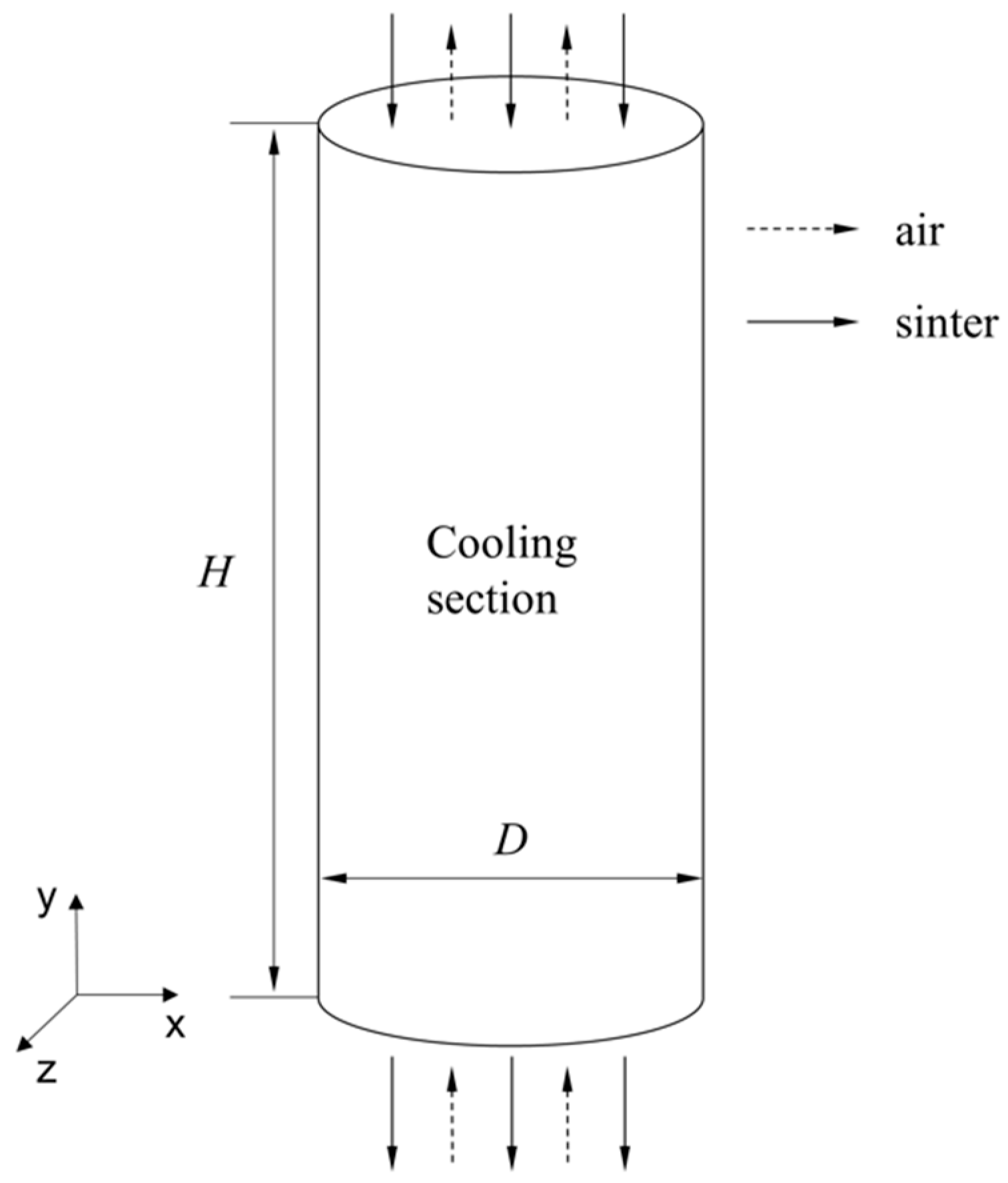
Figure 1 shows the simplified schematic of the computational domain for waste heat recovery in a vertical tank. The inner diameter and height of the cooling section are 1 m and 1.8 m, respectively. The sinter particles with high temperatures fall into the vertical tank from the upper entrance slowly, and then exchange heat with the cooling air from the bottom of the tank. In this way, the high-grade air can be utilized later, such as power generation.
2.2. Mathematical Model and Exergy Destruction Minimization
2.2.1. Mathematical Model
Due to the wide range of sizes and irregular shapes of sinter particles, it is difficult to mathematically describe and numerically investigate the gas solid heat transfer process precisely. In this paper, sinter particles are considered to be spherical particles of equal size and the cooling section of the vertical tank is assumed to be the porous zone. Simultaneously, the radiant heat transfer between/in the sinter particles and the gas is ignored and the wall of the vertical tank is assumed to be insulated. Considering the turbulent flow of the cooling air in the bed layer, the standard turbulent model is adopted. The following equations are employed to describe the gas-solid heat transfer:
The momentum equation of the porous media has additional momentum source terms, which are the momentum loss essentially consisting of two parts, the viscous loss term and the inertial loss term:
The viscous resistance coefficient and inertial resistance coefficient are calculated by the following two equations, respectively [
6]:
Considering the temperatures between the air and the sinter in the vertical tank are different after the heat exchange and this tends to be stable, the local thermal non-equilibrium model is adopted to calculate the heat transfer process. The cooling air as the gas phase and the sinter as the solid phase have independent energy equations. The two energy equations are shown below [
16]:
Solid phase:
where
,
, and
are the density, specific heat, and thermal conductivity, respectively. Their special values are listed in
Table 1. Additionally,
is the volume heat transfer coefficient, which is calculated with the correlation below:
The Nusselt number (
Nu) is calculated as follows by referring to [
16]:
Then, according to the solid phase energy equation, the velocity of the solid is added to the left side of the equation as a source term, which can achieve the slow falling process of sinter particles in the vertical tank and obtain the goal of steady-state gas-solid heat transfer. The source terms in the momentum equation and energy equation are applied into the solution equations through the user-defined functions, as well as the variations of the physical parameters of the air and sinter with temperature.
2.2.2. Exergy Destruction Minimization
As we know, available potential is a state variable, characterizing the ability to do the work of a fluid. The convective heat transfer process can be comprehensively studied from two aspects of heat transfer quantity and heat quality when the available potential is used for the physical analysis of fluid particles. Additionally, exergy is a process variable, representing the change of the available potential and the maximum ability to do the work of a process. It is described as follows [
19]:
where
and
are the enthalpy and entropy in the environmental state, respectively, and
e0 is the available potential of the fluid in the environmental state.
The change of available potential comes from two parts, the heat flow exergy from the outside and the loss generated during the heat transfer. The local destruction rate represents the loss of input exergy during the heat transfer process, thus it is called exergy destruction. The local exergy destruction rate can be expressed as follows [
22]:
where the first item reacts with the irreversible heat loss. The irreversible source is the local temperature gradient. Additionally, it will never be negative, reflecting the irreversibility of the temperature difference heat transfer process. The next item is shown as Equation (13b). In steady-state flow, it is expressed as the product of the velocity and pressure gradient. Liu et al. [
22] considered its physical meaning as the pumping work in the flow process, which includes the change of kinetic energy and viscous loss; that is, mechanical work consumed during the flow. This also meets the understanding in thermodynamics that the mechanical work lost during the flow is all mechanical exergy.
The proposed local exergy destruction rate provides the possibility to quantitatively analyse the irreversibility of each point during the process. The total exergy destruction caused by heat transfer and fluid flow can be synthesized:
According to Equation (14), the total exergy destruction consists of the thermal dissipation owing to a temperature difference and the power consumption owing to a pressure drop, which are adopted to respectively represent the irreversible heat loss and the irreversible pressure loss of the gas-solid heat transfer process.
3. Results and Discussion
3.1. Grid Independence Analysis and Model Validation
3.1.1. Grid independence Analysis
A two-dimensional structured symmetrical grid with hexahedral elements was conducted in CFD software ICEM. The multi-layer encrypted grid is used for the strong heat transfer section of the wall boundary layer. To avoid the effect of the quality of the grid and to improve the accuracy of calculation results, the grid independence should be analyzed. The main parameters and their values are shown in
Table 1. The boundary conditions are the mass-flow-inlet for the gas inlet, the pressure-out for the gas outlet, and the adiabatic-wall for the walls of the computational domain. Combined with the additive source term in the solid energy equation, the solid inlet is set to be the isothermal-wall boundary condition, which can achieve the slow falling process of sinter particles.
According to the results of the grid independence shown in
Table 2, the number of the grid elements varies from 12,000 to 40,000. The calculation using the mesh system with 12,000 grid elements is different to converge unless the relaxation factor of energy is adjusted to a very low level, which will greatly increase the time for calculation convergence. Therefore, the model with 12,000 grid elements was been adopted. The relative errors between the results of 14,400, 18,000, and 28,000 grid elements and the result of 40,000 grid elements are all less than 1%, small enough to achieve the requirement for accuracy. Furthermore, because the calculation time required for grids with 14,400 and 18,000 elements is similar, so the model with 18,000 grid elements is selected for the consecutive numerical calculation.
3.1.2. Model Validation
To validate the accuracy and reliability of the numerical model in this study, some results in [
13,
14] are applied. In [
14], gas-solid heat transfer characteristics were experimentally studied in the sinter vertical tank through a homemade experimental setup, and an experimental correlation for describing the gas-solid heat transfer characteristics was obtained. In [
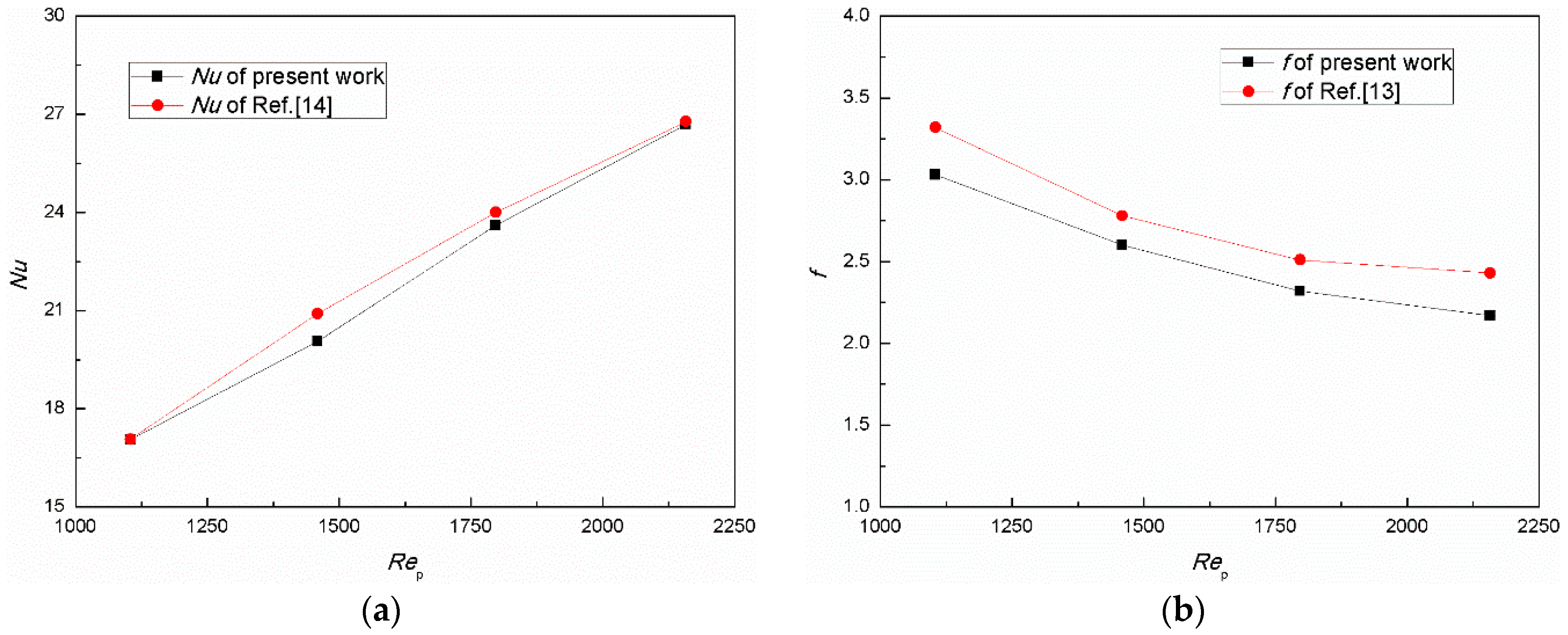
13], the Ergun’s correlation in a vertical tank was experimentally modified. The comparison of the Nusselt number (
Nu) between the numerical study in this paper and the experimental results in [
14] under different
Rep is shown in
Figure 2a. Additionally,
Figure 2b shows the comparison of the fraction factor (
f) obtained in the present work and the experimental results in [
13]. Excluding the air mass flow rate, the other main parameters and their values of the numerical conditions are shown in
Table 1. As can be seen from
Figure 2, the deviations of
Nu between the numerical results and the experimental results are all less than 5% and the maximum is 4.18%, and the maximum error off is 10.69%. Due to the inhomogeneity and irregularity of sinter particles, the uncertainty in the experimental measurement and the idealization of numerical simulation, the deviations are within the acceptable range and the computational model in the present work is certified to be reasonably reliable.
3.2. Analysis of Influencing Parameters
As is known from the previous numerical and experimental studies, the inlet gaseous velocity and the porosity are the main influencing factors on the solid cooling process. Since the sinter particles are assumed to be equal-diameter spherical particles, the porosity of the sinter bed layer is mainly determined by the particle diameter. Therefore, under the specified structure of the sinter vertical tank in this work, the air mass flow rate, sinter mass flow rate, and sinter particle diameter are the three operating parameters to be studied numerically to obtain the impacts on the waste heat recovery efficiency of the gas-solid heat transfer process.
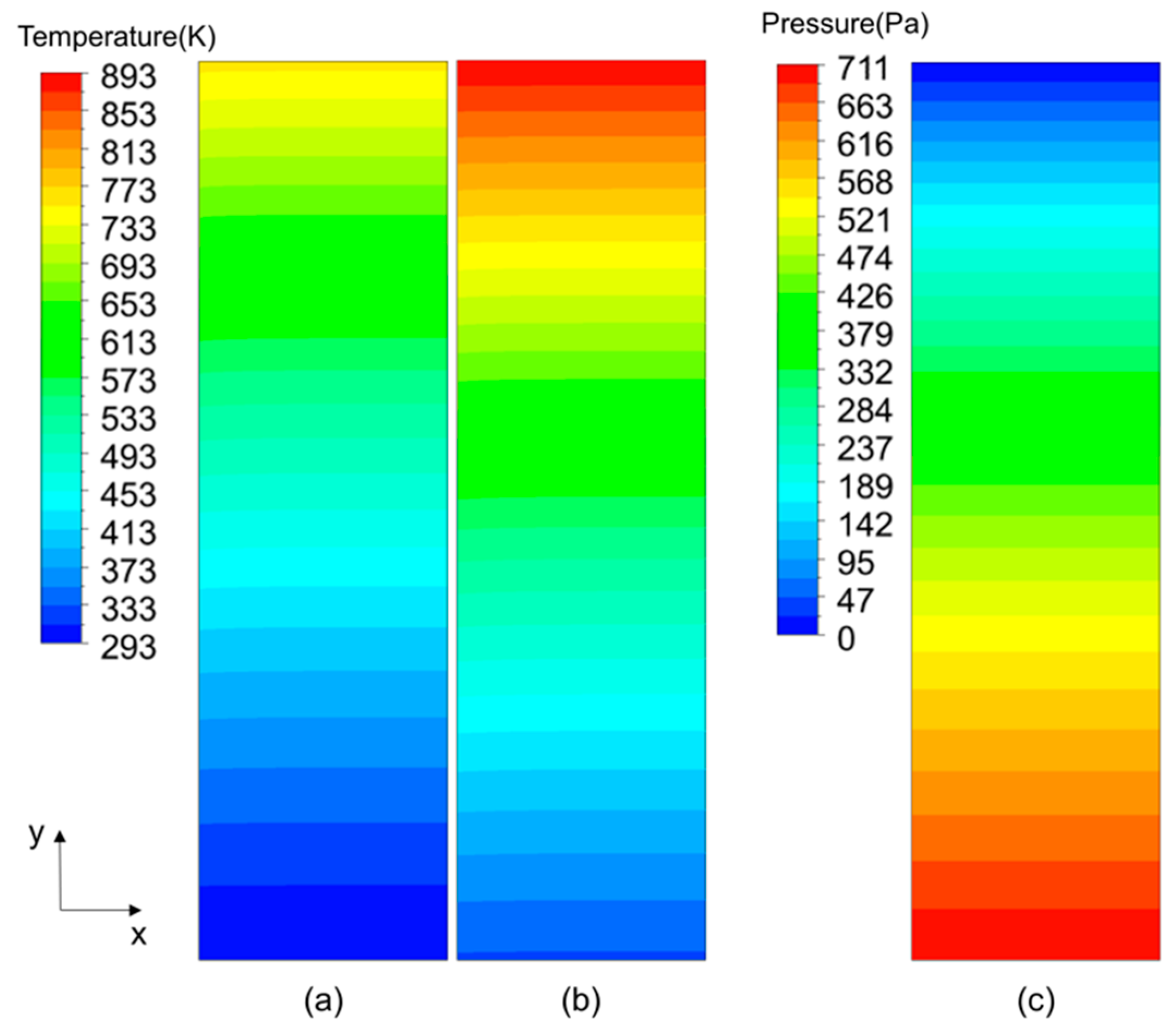
Figure 3 shows the air temperature distribution, sinter temperature distribution, and the pressure distribution in the cooling section when the gas-solid heat exchange is stable. Since the numerical simulation in the present work is based on a two-dimensional axisymmetric model,
Figure 3 only shows half of the computational domain and the y axis is the direction of the gas flow. The settings of the partial parameters are listed in
Table 1. As we can see in
Figure 3, the air temperature in the top of cooling section is obviously higher than in the bottom, which is contrary to the result of the sinter, and the pressure from the bottom to the top is significantly reduced.
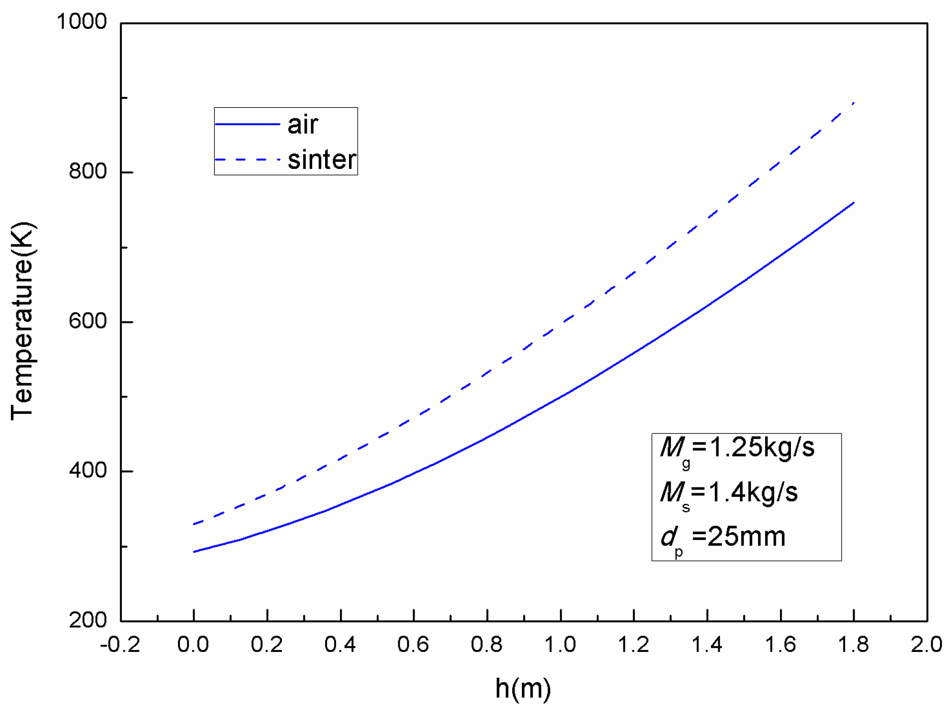
Figure 4 shows the average cross-sectional temperatures of the air and sinter along the height of the sinter bed layer. Additionally, the temperatures of the air and sinter on the same radial cross section are different. However, since the gas-solid heat transfer process in the cooling section is steady, the air outlet temperature only rises to 760 K lower than 893 K and the sinter outlet temperature drops to 330 K higher than 293 K. In addition, the gas-solid temperature differences of different sections along the height of the bed are approximately equal due to the steady heat transfer process.
The influences of a single parameter on the flow and heat transfer performances evaluated by the thermal dissipation and the power consumption were investigated in the model described above by changing one parameter to several different levels while keeping the other parameters fixed. The values of the parameters at the four levels are shown in
Table 3. The ranges of these parameters are set by reference to the homemade experimental setup in [
13,
14] and the considerations of the quality and quantity of waste heat recovery. The results and analysis are as follows.
3.2.1. Influence of Air Flow Rate
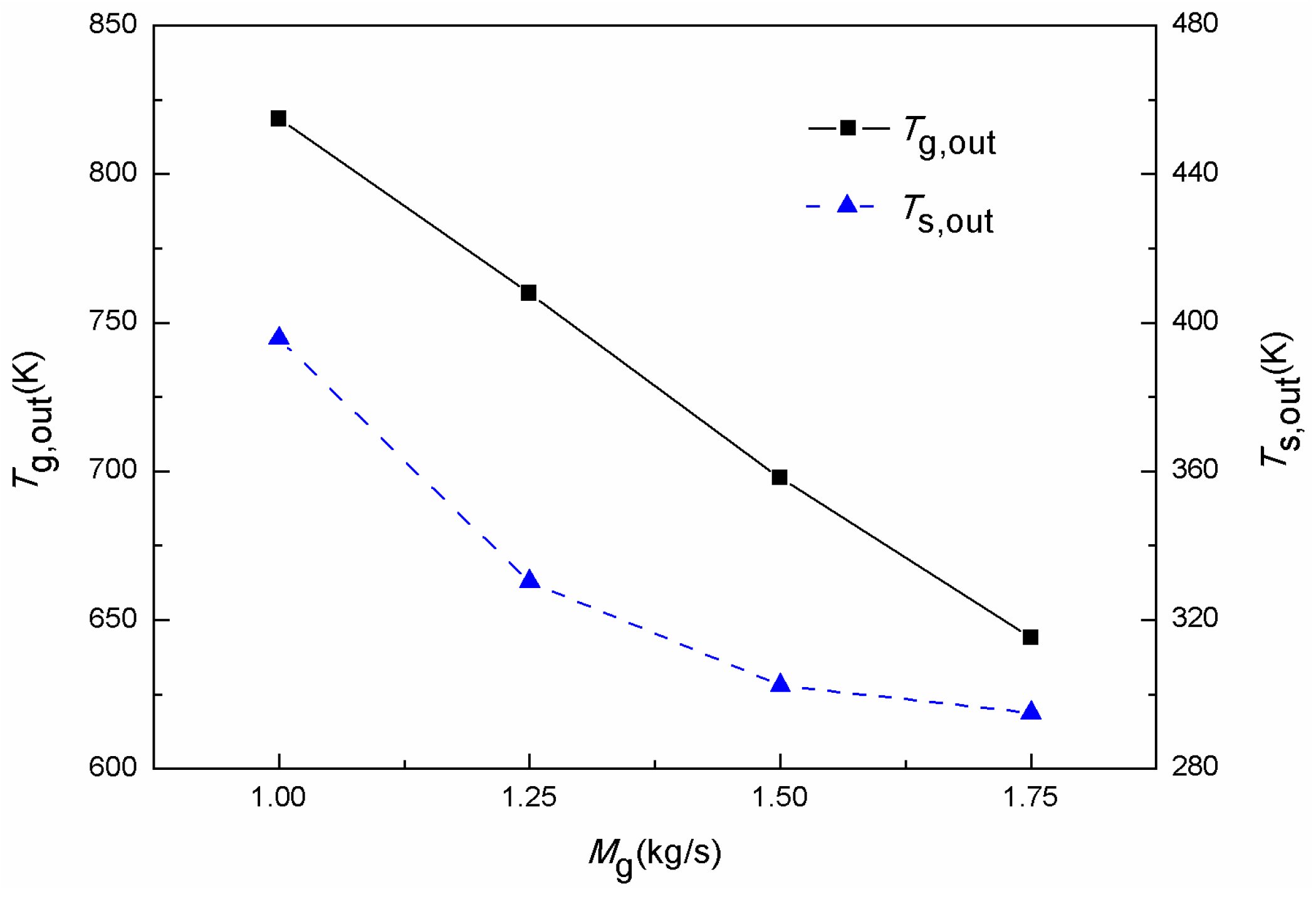
Figure 5 shows the trends of the outlet air temperature and outlet sinter temperature with the increase of air mass flow rate, when the sinter mass flow rate is 1.4 kg/s and sinter particle diameter is 25 mm. As seen from the figure, the outlet air temperature and outlet sinter temperature both decrease while the air flow rate is increasing. According to the energy conservation law, for the given inlet sinter temperature and given sinter falling speed, the outlet air temperature decreases with the increase of the air flow rate. Then, the increase of the air flow rate results in an increase of the inlet air velocity, which is in favor of improving the convective heat transfer coefficient between the air and sinter, and causes an increase of the sinter cooling rate. Therefore, the outlet sinter temperature also decreases gradually. In addition,
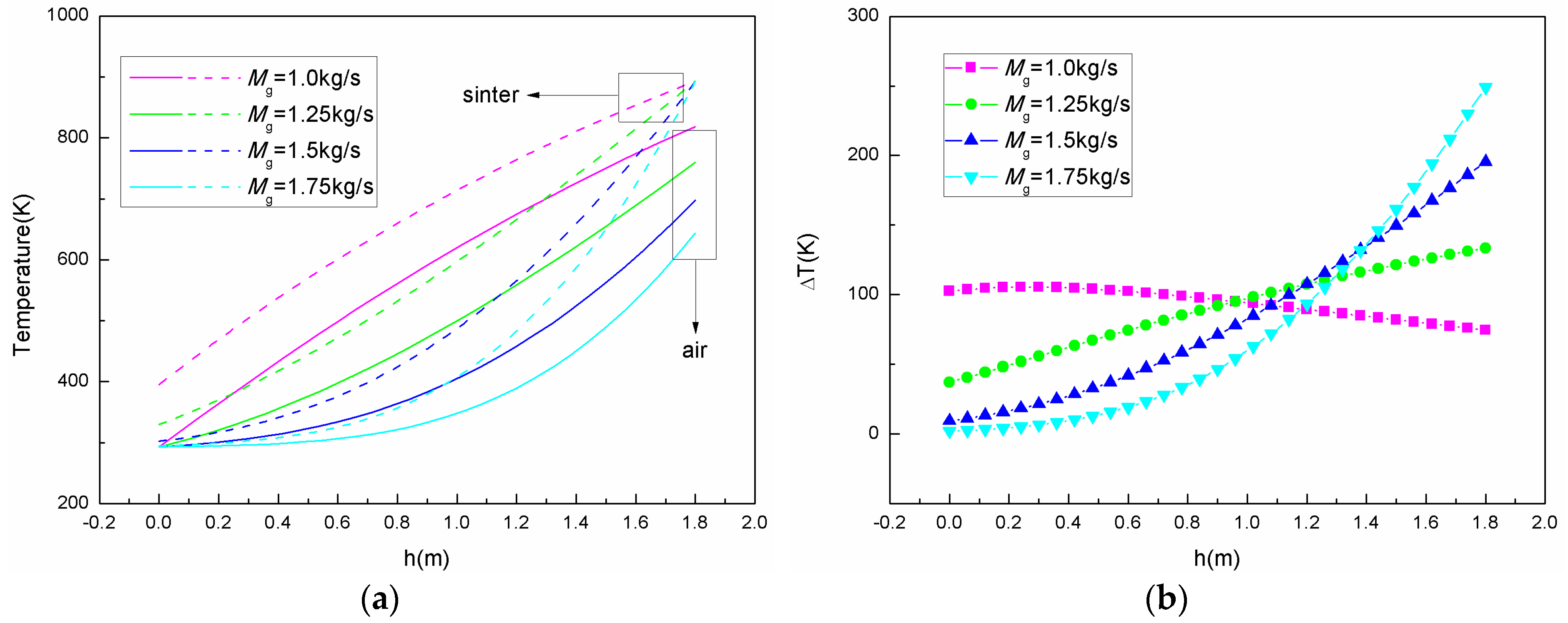
Figure 6a shows the average cross-sectional temperature distribution of the air and sinter along the height of the sinter bed layer for different air mass flow rates.
Figure 6b shows the temperature differences between the sinter and air along the height of the sinter bed layer. For a given air mass flow rate, although the gas-solid temperature difference is not the same at the different heights of the bed, the temperature trends of the gas and solid are the same. This is an embodiment of the gas-solid steady heat transfer process based on the local non-equilibrium model.
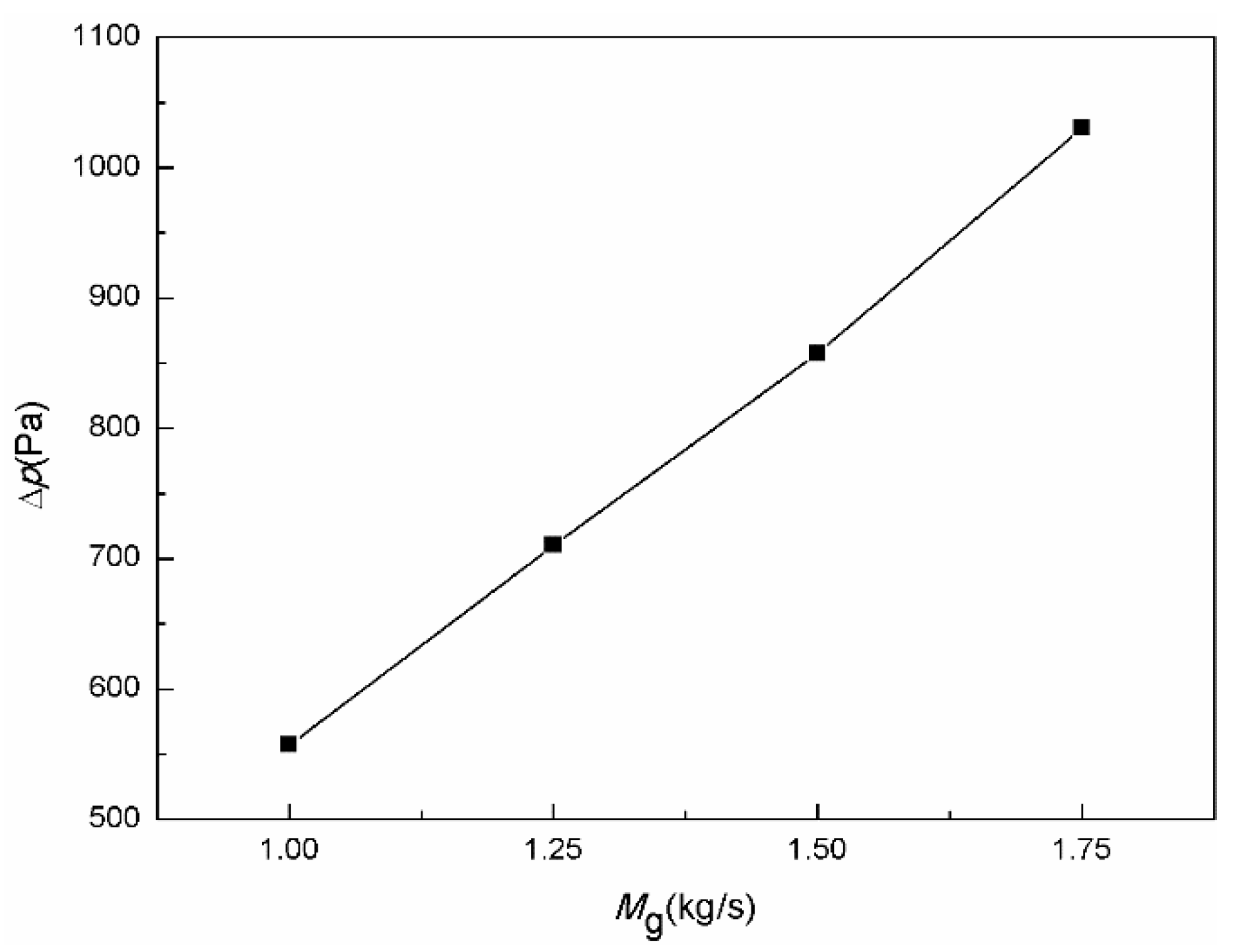
Figure 7 shows the influence of the air flow rate on the pressure drop of the sinter bed layer. As we can see, the pressure drop increases gradually with an increase of the air flow rate. This can be explained as the increased air flow rate leads to increased resistance and then results in an increase of the pressure drop in the vertical tank.
To comprehensively analyze the heat transfer quantity and energy quality of the convective heat transfer process, the influences of the air flow rate on the irreversible heat loss and the irreversible pressure loss were investigated.
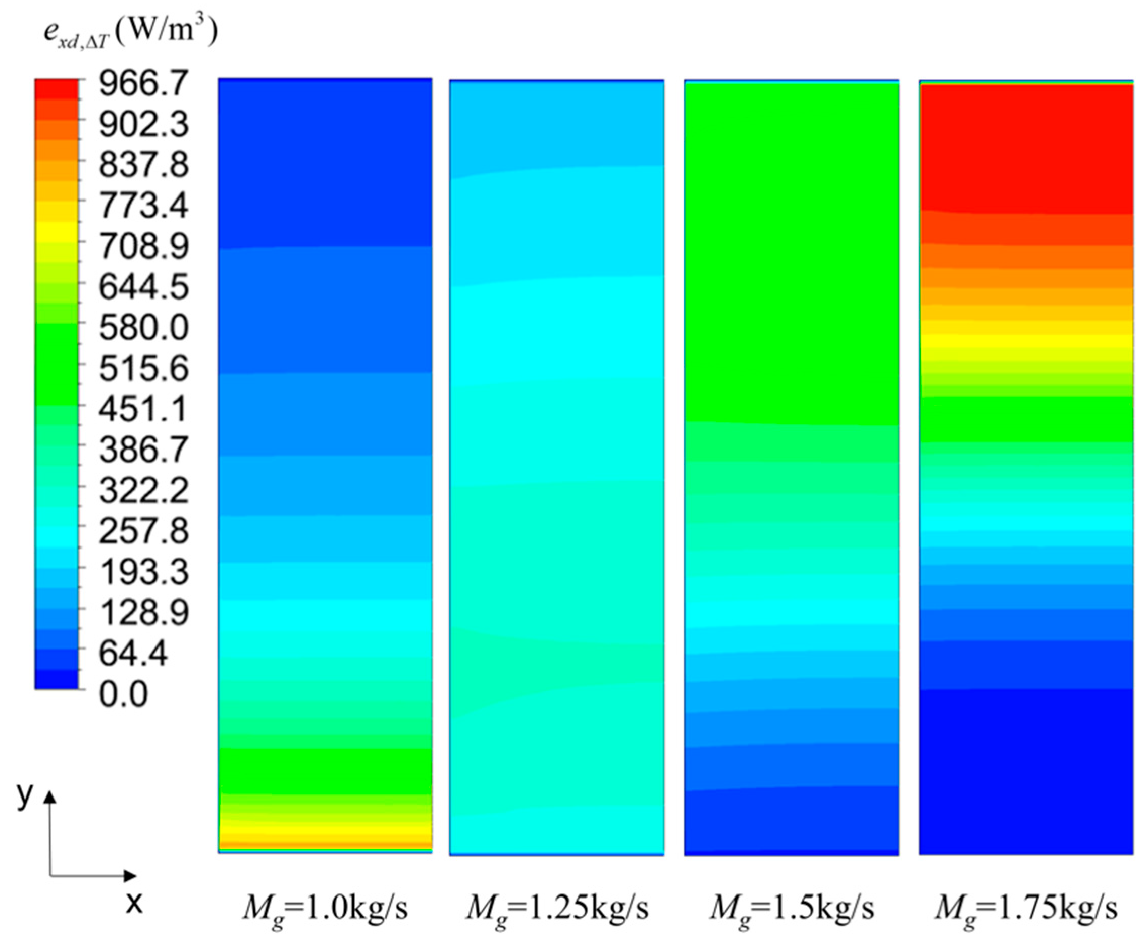
Figure 8 shows the distributions of the local heat transfer exergy destruction rate of the solid domain when the air flow rate is 1.0 kg/s, 1.25 kg/s, 1.5 kg/s, and 1.75 kg/s, respectively. According to Equation (13a), the local heat transfer exergy destruction rate is mainly caused by a temperature difference and it is related to the thermal conductivity. Since the thermal conductivity of sinter is much higher than that of air, for the convenience of the analysis, only the local heat transfer exergy destruction rate of sinter is given here. By analyzing and comparing
Figure 6a and
Figure 8, it can be found that the temperature gradient trends of sinter correspond to the distributions of the local heat transfer exergy distribution rate.
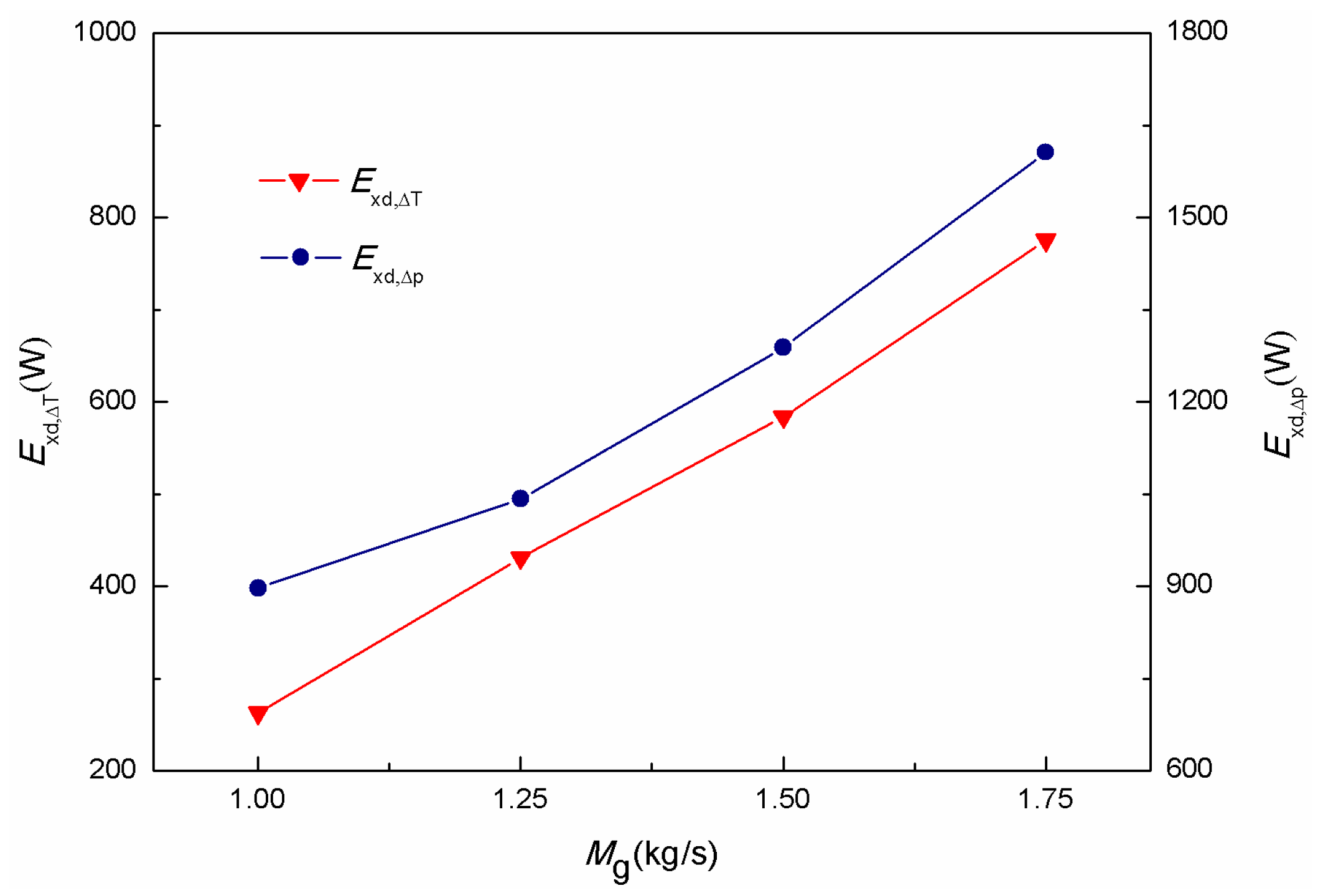
Figure 9 shows the exergy destruction caused by heat transfer and by fluid flow changing with the increase of the air mass flow rate, respectively. The local exergy destruction rate gradually increases when the air flow rate rises from 1.0 kg/s to 1.75 kg/s, as shown in
Figure 8, which corresponds to the result of the exergy destruction caused by heat transfer in the
Figure 9. As for the exergy destruction caused by fluid flow, it can be explained as the increase of the air flow rate leads to an increase of resistance during the flow, and then results in an increase of power consumption. Therefore, the exergy destruction by fluid flow gradually increases with the increase of the air flow rate.
3.2.2. Influence of the Sinter Flow Rate
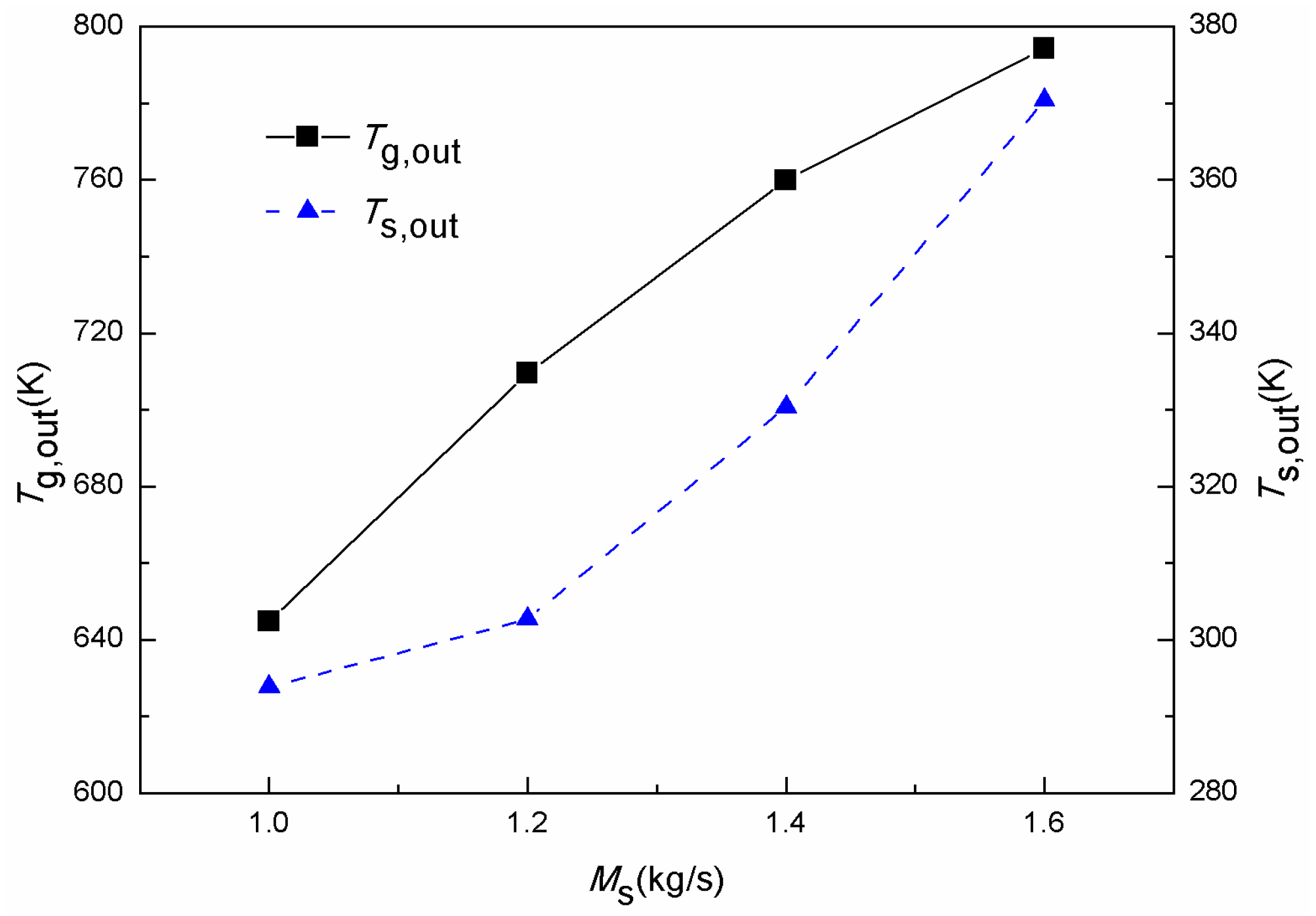
Figure 10 shows the variations of the outlet air temperature and outlet sinter temperature with the sinter mass flow rate, when the air mass flow rate is 1.25 kg/s and the sinter particle diameter is 25 mm. As we can see, with the increasing of the sinter flow rate, the outlet air temperature and outlet sinter temperature all increase. It can be explained as the increase of the sinter flow rate leads to a decrease of the resident time of sinter particles in the vertical tank. The sinter particles have not yet fully exchanged heat with the air and quickly fall to the bottom of the vertical tank. Therefore, the outlet sinter temperature increases with an increase of the sinter flow rate. Then, for a given air flow rate and sinter particle diameter, the outlet air temperature will increase because of the increase of the sinter average temperature. Furthermore,
Figure 11a shows the average cross-sectional temperature distribution of air and sinter along the height of the sinter bed layer for different sinter mass flow rates.
Figure 11b shows the temperature differences between sinter and air along the height of the sinter bed layer.
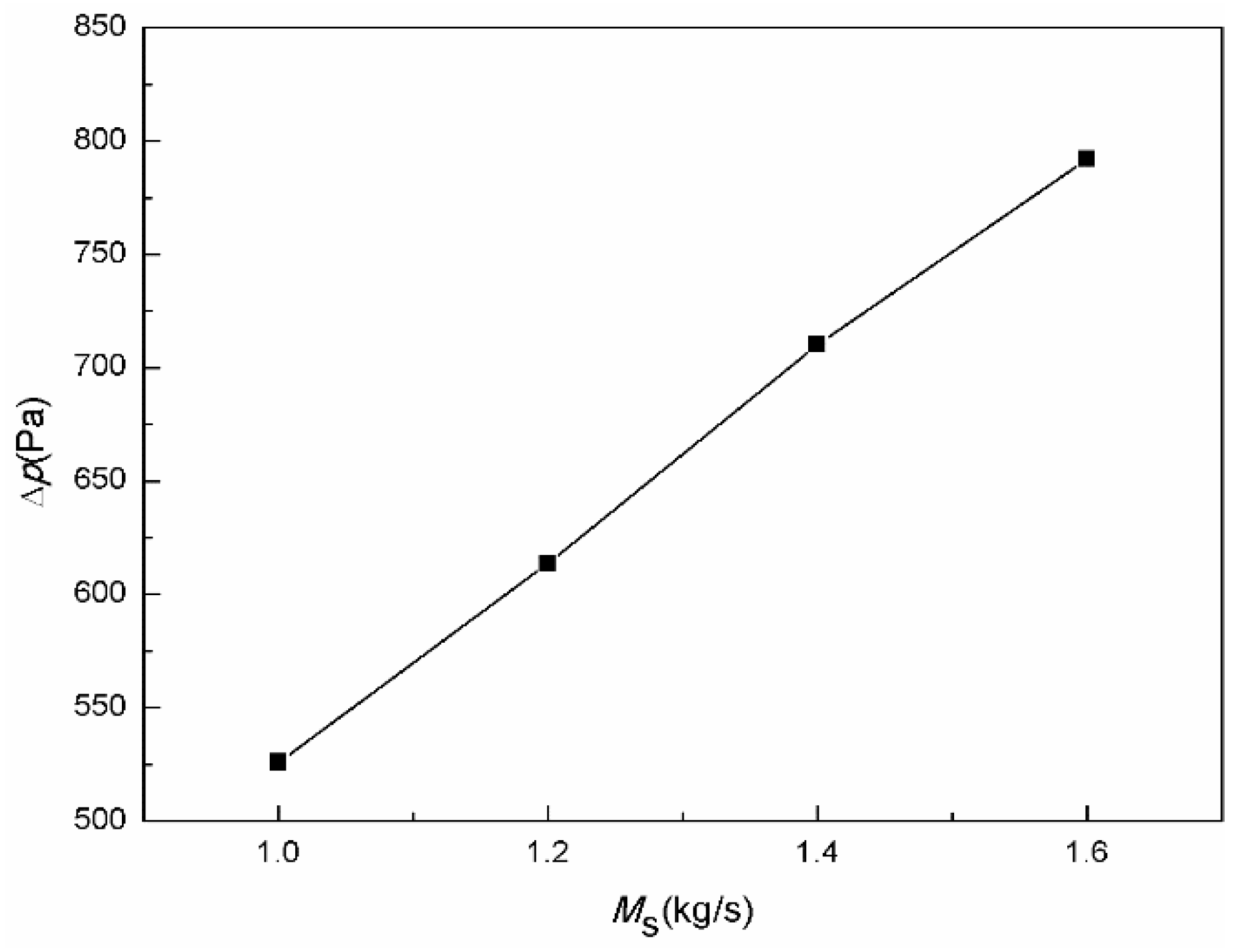
Figure 12 shows the influence of the sinter flow rate on the pressure drop from the bottom of the sinter bed layer to the top. Similar to the result caused by increasing the air flow rate, the pressure drop gradually increases with the increase of the sinter flow rate due to the increased resistance.
Similarly, the influences of the sinter flow rate on thermal consumption and power consumption were investigated in this work.
Figure 13 shows the distributions of the local heat transfer exergy destruction rate of the sinter for different sinter mass flow rates. When the sinter mass flow rate is 1.0 kg/s and 1.2 kg/s, the local heat transfer exergy destruction rate of the sinter increases along the height of the sinter bed layer. This result can be verified from the trend of sinter temperature variation in
Figure 11a. Then, the local exergy destruction rate gradually decreases when the sinter flow rate rises from 1.0 kg/s to 1.6 kg/s, corresponding to the result of the exergy destruction caused by heat transfer in
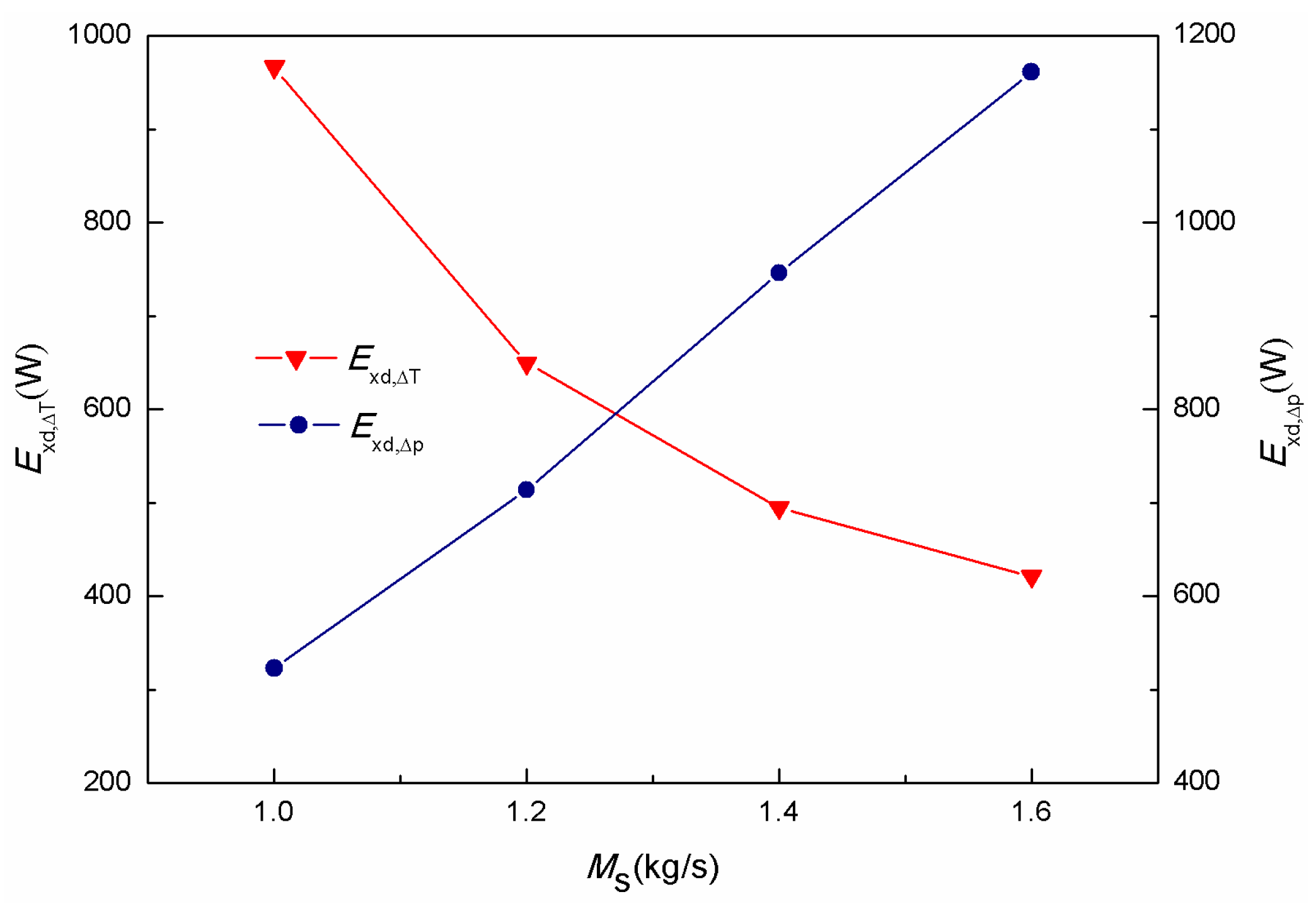
Figure 14. It indicates that the irreversible heat loss of the cooling section in the sinter tank decreases with the increase of the sinter mass flow rate.
Figure 14 also shows the variety of exergy destruction caused by fluid flow with different sinter flow rates. Similar to the effect of the air flow rate, the increase of the sinter flow rate leads to an increase of the resistance during the flow, and then results in an increased power consumption and exergy destruction caused by the fluid flow increasing.
3.2.3. Influence of Sinter Particle Diameter
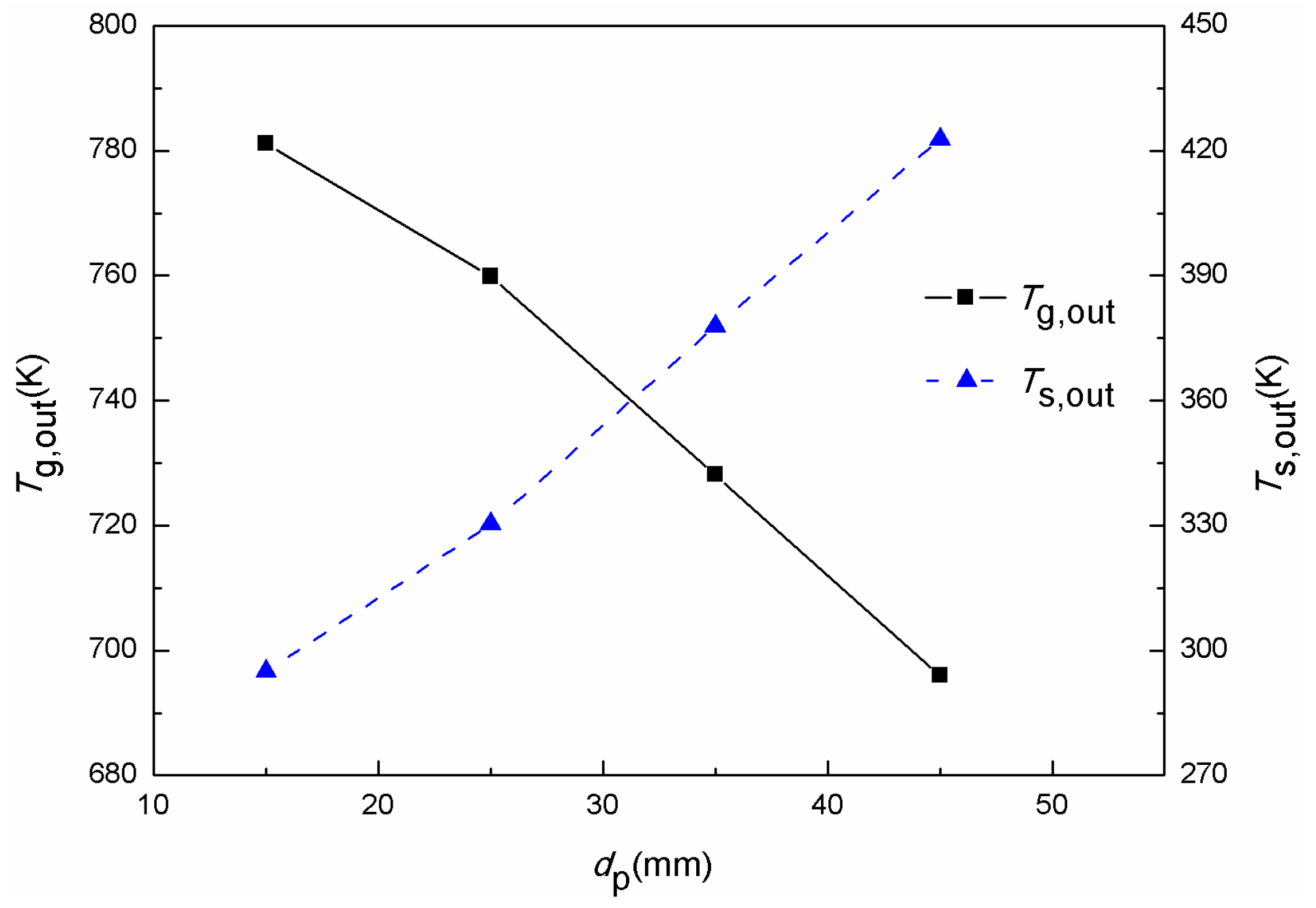
Figure 15 shows the variations of the outlet air temperature and outlet sinter temperature with the sinter particle diameter when air mass flow rate is 1.25 kg/s and sinter mass flow rate is 1.4 kg/s. With the increasing of the sinter particle diameter, the outlet air temperature decreases and the outlet sinter temperature increases. This is because the conduction heat transfer in the sinter particles declines due to the increase of particle thermal resistance caused by the increase of the sinter particle diameter. At the same time, the gas-solid heat transfer area decreases while the sinter particle diameter increases. Therefore, the sinter cooling rate decreases, and results in a decrease of the outlet air temperature and an increase of the outlet sinter temperature. In addition,
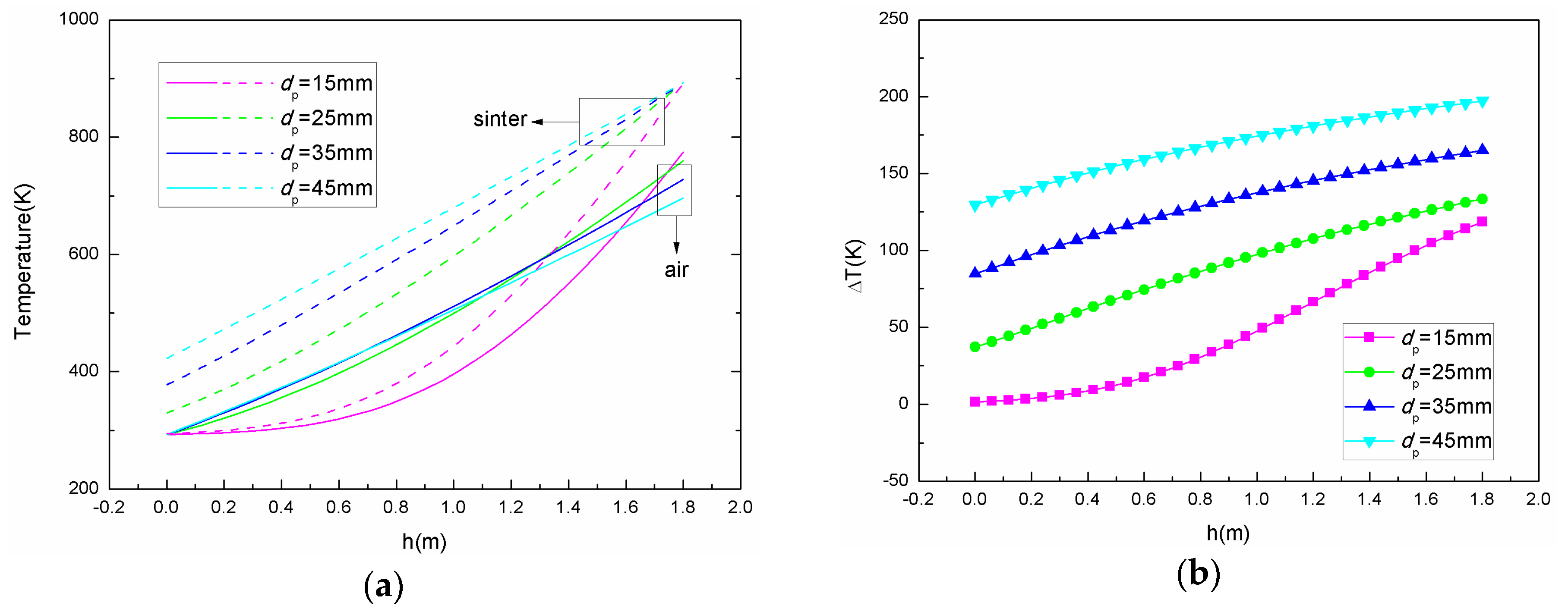
Figure 16a shows the average cross-sectional temperature distribution of air and sinter along the height of the sinter bed layer for different sinter particle diameters.
Figure 16b shows the temperature differences between sinter and air along the height of the sinter bed layer. Different from the condition with a sinter particle diameter of 15 mm, when the sinter particle diameter is 25 mm, 35 mm, and 45 mm, the temperature variation in the vertical tank is similar; the temperature difference between the sinter and air along the sinter bed layer height rises more gently.
Then,
Figure 17 shows the influence of sinter particle diameter on the pressure drop from the bottom of the sinter bed layer to the top. The increase of the sinter particle diameter leads to an increase of the porosity of the sinter bed layer, which reduces the resistance and pressure drop of the air flow.
We also performed exergy destruction analysis.
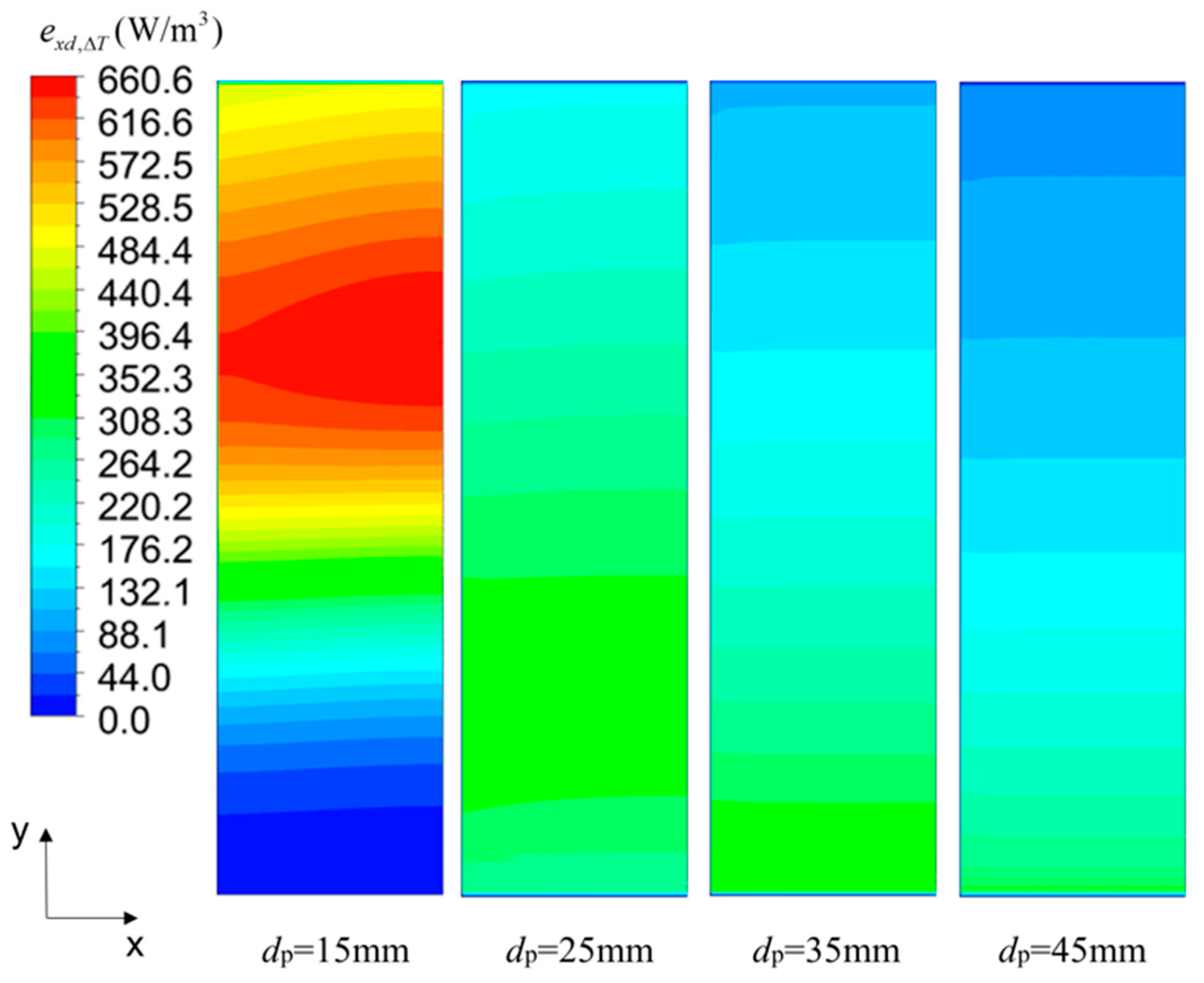
Figure 18 shows the distributions of the local heat transfer exergy destruction rate of sinter when the sinter particle diameter is 15 mm, 25 mm, 35 mm, and 45 mm respectively. Additionally, the influences of sinter particle diameter on exergy destruction caused by heat transfer and caused by fluid flow can be seen in
Figure 19. As we can see, the local exergy destruction rate gradually decreases when the sinter particle diameter rises from 15 mm to 45 mm, corresponding to the result of the exergy destruction caused by heat transfer in
Figure 19.
Figure 19 also shows that the exergy destruction caused by the pressure drop gradually decreases with the sinter diameter increasing due to the increased porosity of the sinter bed layer. It indicates that the smaller the particle diameter, the greater the heat dissipation and power consumption.
4. Parameter Optimization
The results of a single parameter’s influences on the flow and heat transfer performance, respectively representing the irreversible heat loss and irreversible pressure loss of the waste heat recovery process, were obtained. Considering the two objectives are not independent, optimizing one of the goals must be at the expense of the other one during the parameter optimization. To obtain the suitable combination of the air mass flow rate, the sinter mass flow rate, and the sinter particle diameter, a multi-objective genetic algorithm adept in searching globally combined with a BP neural network adept in searching locally was employed in the parameter optimization, which improves the convergence accuracy and rate and reduces the workload greatly.
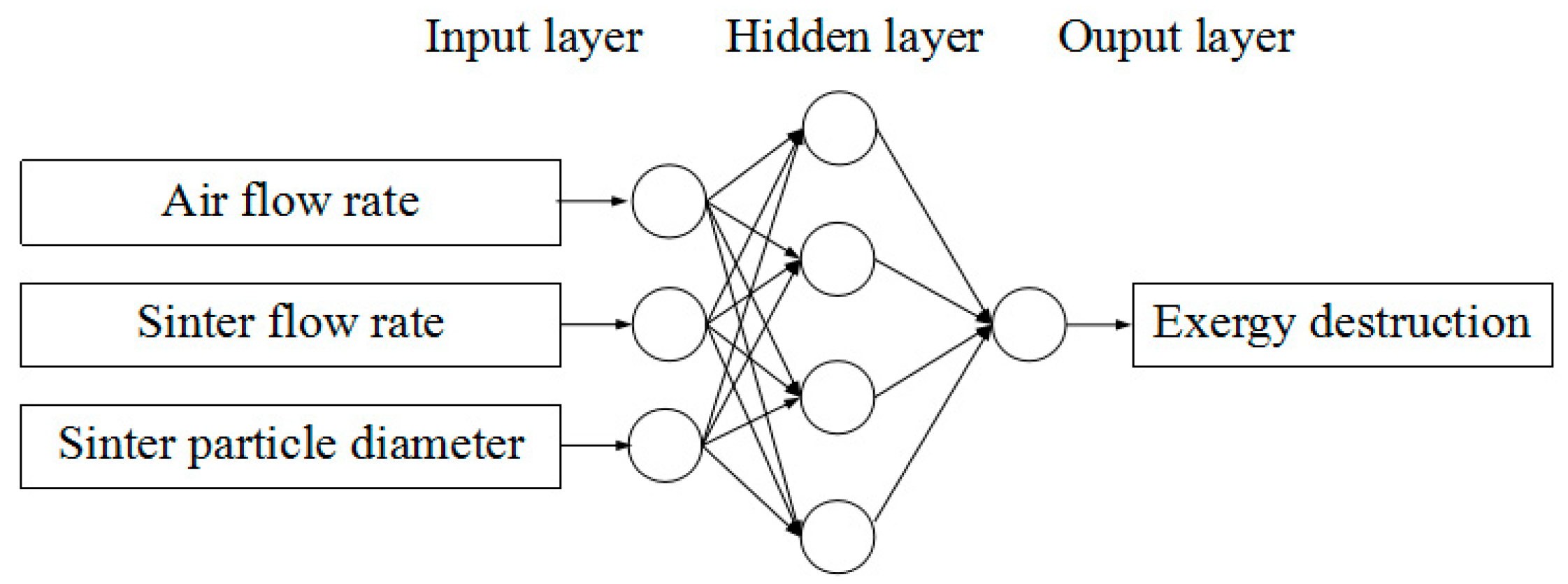
The structure of the BP neural network in the parameter optimization of the gas-solid heat transfer is shown in
Figure 20. Sixty-four sets of samples were selected, of which 51 were used as training samples and 13 were used as test samples in the two neural networks with exergy destruction caused by heat transfer and by fluid flow, respectively. Each set of sample consists of four data, of which the air flow rate, the sinter flow rate, and the sinter particle diameter were used as the input layer neurons and the exergy destruction was used as output layer neurons.
The multi-objective genetic algorithm with the exergy destruction caused by heat transfer and by fluid flow as the objectives sets the population size to 70, the generation to 300, and the convergence criterion to 10
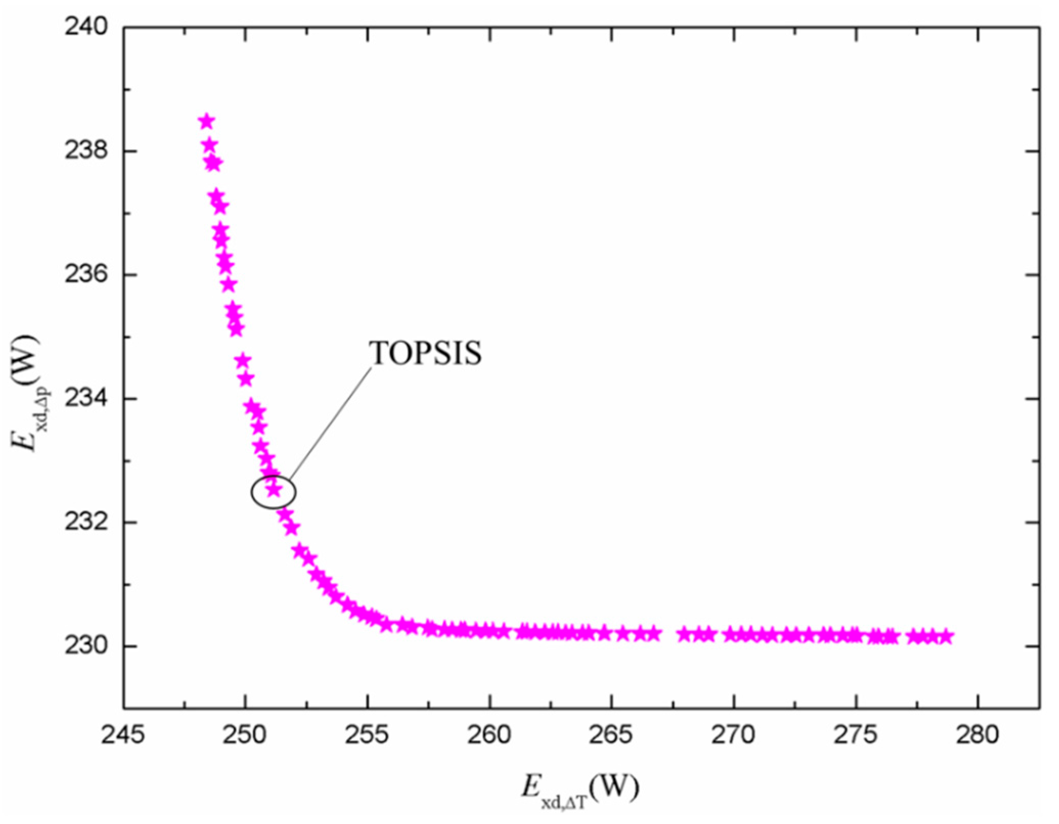
−4. The initial range settings are 0.3 kg/s to 3 kg/s, 0.3 kg/s to 3 kg/s, and 3 mm to 50 mm for the air flow rate, sinter flow rate, and sinter particle diameter, respectively. The Pareto frontier derived from the multi-objective optimization algorithm is shown in
Figure 21. The results show that
of Pareto solutions varies from 248.41 W to 278.67 W, while
varies from 230.16 W to 238.48 W, respectively. However, the best one cannot be chosen from Pareto front based only on the size of the two function values. Then, a decision maker technique, Technique for Order Preference by Similarity to an Ideal Solution (TOPSIS), was applied determine the best solution. The basic principle of TOPSIS is that the chosen one should have the shortest distance from the positive ideal solution and the longest distance from the negative ideal solution [
30]. The results can be seen in
Figure 21. The exergy destruction caused by heat transfer and by fluid flow of the optimal solution are 251.16 W and 232.53 W, respectively, and the corresponding value of the three parameters are 2.99 kg/s, 0.61 kg/s, and 32.8 mm, respectively, with the structural parameters fixed. The optimal solution minimizes the exergy destruction and minimizes the irreversible loss.
5. Conclusions
The goal of this study was to investigate numerically how several operating parameters affect the gas-solid heat transfer process in a vertical tank for sinter waste heat recovery, and then to obtain an optimal combination of these operating parameters of a vertical tank with the given structural parameters through suitable evaluation and an optimization method. The following conclusions were acquired.
(1) The two-dimensional gas-solid heat transfer mathematical model, which was established based on the porous media model, standard turbulence model, and local thermal non-equilibrium model, can be used to investigate the heat recovery of the sinter.
(2) The numerical results show that the outlet air and sinter temperatures increase while decreasing the air flow rate or increasing the sinter flow rate. By increasing the sinter particle diameter, the outlet air temperatures decrease and the outlet sinter temperatures increase. The pressure drops decrease while increasing the air flow rate or the sinter particle diameter and decreasing the sinter flow rate or the sinter initial temperature.
(3) Using the exergy destruction minimization as the evaluation method, the exergy destruction caused by heat transfer and by fluid flow both gradually increase with an increase of the air mass flow rate. Additionally, the increase of the sinter flow rate results in a decrease of the exergy destruction caused by heat transfer and an increase of the exergy destruction caused by fluid flow. In addition, the exergy destruction caused by heat transfer and by fluid flow both gradually decrease with an increase of the sinter particle diameter.
(4) The optimal solution for exergy destruction minimization was obtained through the multi-objective genetic algorithm with a BP neural network. For the given structure of a vertical tank, the optimal operating parameters are 2.99 kg/s, 0.61 kg/s, and 32.8 mm for the air flow rate, sinter flow rate, and sinter diameter, respectively.
Adopting the principle of convective heat transfer enhancement based on exergy destruction minimization could provide a guide to develop new heat transfer techniques in waste heat recovery. For further engineering applications, the optimization methods mentioned in this paper can be used to optimize operating parameters when the structure of a vertical tank is given and can also be applied to obtain the most suitable structural parameters, such as the inner diameter and height of the vertical tank when the output of the sinter or other particulates is fixed. Therefore, the applications of exergy destruction minimization and the genetic algorithm would be helpful for further theoretical research on the enhancement of gas solid heat transfer and engineering applications of particulate waste heat recovery.
Author Contributions
Conceptualization, Z.L.; software, Z.L. and W.L.; methodology, formal analysis, Z.L., C.X. and S.W.; data curation, S.W.; investigation, C.X.; writing—original draft preparation, C.X.; writing—review and editing, C.X.; supervision, Z.L. and W.L.
Funding
This research was funded by the National Key R&D Program of China (No.2017YFB0603501).
Conflicts of Interest
The authors declare no conflict of interest.
Nomenclature
| H | height of cooling section (m) |
| D | inner diameter of cooling section (m) |
| h | area heat transfer coefficient (W/(m2·K)) |
| hV | volume heat transfer coefficient (W/(m3·K)) |
| 1/a | viscous resistance coefficient (–) |
| C2 | inertial resistance coefficient (–) |
| c | specific heat (J/(kg·K)) |
| ε | bed layer voidage (–) |
| dp | sinter particle diameter (m) |
| ρ | Density (kg/m3) |
| μ | dynamic viscosity (kg/(m·s)) |
| λ | thermal conductivity (W/(m·K)) |
| e | the available potential (J) |
| exd | the local exergy destruction rate (W/m3) |
| Exd,ΔT | exergy destruction caused by heat transfer (W) |
| Exd,Δp | exergy destruction caused by pressure drop (W) |
| u | superficial velocity (m/s) |
| Subscripts | |
| g | air |
| s | sinter |
| in | inlet |
| out | outlet |
References
- Cai, J.J.; Wang, J.J.; Chen, C.X.; Lu, Z.W. Waste heat recovery and utilization in iron and steel industry. Iron Steel 2007, 42, 1–7. (In Chinese) [Google Scholar]
- Ammar, Y.; Joyce, S.; Norman, R.; Wang, Y.D.; Roskilly, A.P. Low grade thermal energy sources and uses from the process industry in the UK. Appl. Energy 2012, 9, 3–20. [Google Scholar] [CrossRef]
- Liu, Y.; Yang, J.; Wang, J.; Cheng, Z.L.; Wang, Q.W. Energy and exergy analysis for waste heat cascade utilization in sinter cooling bed. Energy 2014, 67, 370–380. [Google Scholar] [CrossRef]
- Leong, J.C.; Jin, K.W.; Shiau, J.S.; Jeng, T.M.; Tai, C.H. Effect of sinter layer porosity distribution on flow and temperature fields in a sinter cooler. Int. J. Min. Metall. Mater. 2009, 16, 265–272. [Google Scholar] [CrossRef]
- Shi, H.Z.; Wen, Z.; Zhang, X.; Lou, G.F. Numerical simulation and parameter analysis of high temperature sinter gas-solid heat transfer process. Ironmak. Steelmak. 2011, 33, 339–345. [Google Scholar]
- Zhang, X.H.; Chen, Z.; Zhang, J.Y.; Ding, P.X.; Zhou, J.M. Simulation and optimization of waste heat recovery in sinter cooling process. Appl. Therm. Eng. 2013, 54, 7–15. [Google Scholar] [CrossRef]
- Pan, L.S.; Wei, X.L.; Peng, Y.; Ma, Y.J.; Li, B. Theoretical study on the cooling procedure for vertical flow sinters. Appl. Therm. Eng. 2017, 127, 592–601. [Google Scholar] [CrossRef]
- Feng, J.S.; Dong, H.; Gao, J.Y.; Liu, J.Y.; Liang, K. Exergy transfer characteristics of gas-solid heat transfer through sinter bed layer in vertical tank. Energy 2016, 111, 154–164. [Google Scholar] [CrossRef]
- Caputo, A.C.; Cardarelli, G.; Pelagagge, P.M. Analysis of heat recovery in gas solid moving beds using a simulation approach. Appl. Therm. Eng 1996, 16, 89–99. [Google Scholar] [CrossRef]
- Wen, Z.; Shi, H.Z.; Zhang, X.; Lou, G.F.; Liu, X.L.; Dou, R.F.; Su, F.Y. Numerical simulation and parameters optimization on gas-solid heat transfer process of high temperature sinter. Ironmak. Steelmak. 2011, 38, 525–529. [Google Scholar] [CrossRef]
- Liu, Y.; Wang, J.Y.; Cheng, J.L.; Yang, J.; Wang, Q.W. Experimental investigation of fluid flow and heat transfer in a randomly packed bed of sinter particles. Int. J. Heat Mass Transf. 2016, 99, 589–598. [Google Scholar] [CrossRef]
- Feng, J.S.; Dong, H.; Liu, J.Y.; Liang, K.; Gao, J.Y. Experimental study of gas flow characteristics in vertical tank for sinter waste heat recovery. Appl. Therm. Eng. 2015, 91, 73–79. [Google Scholar] [CrossRef]
- Feng, J.S.; Dong, H.; Dong, H.D. Modification of Ergun’s correlation in vertical tank for sinter waste heat recovery. Powder Technol. 2015, 280, 89–93. [Google Scholar] [CrossRef]
- Feng, J.S.; Dong, H.; Gao, J.Y.; Liu, J.Y.; Liang, K. Experimental study of gas–solid overall heat transfer coefficient in vertical tank for sinter waste heat recovery. Appl. Therm. Eng. 2016, 95, 136–142. [Google Scholar] [CrossRef]
- Kong, N.; Wen, Z.; Feng, J.X. Study on Mathematical Model of Flow and Heat Transfer Process in Dry Quenching Furnace. Jin Autom. 2004, 3, 27–30. (In Chinese) [Google Scholar]
- Feng, J.S.; Dong, H.; Gao, J.Y.; Li, H.Z.; Liu, J.Y. Numerical investigation of gas-solid heat transfer process in vertical tank for sinter waste heat recovery. Appl. Therm. Eng. 2016, 107, 135–143. [Google Scholar] [CrossRef]
- Gao, J.Y.; Feng, J.S.; Dong, H. Study of evaluation index for thermal parameters optimization of vertical tank for sinter waste heat recovery. Metall. Energy 2017, 36, 46–49. (In Chinese) [Google Scholar]
- Liu, W.; Liu, Z.; Jia, H.; Fan, A.; Nakayama, A. Entransy expression of the second law of thermodynamics and its application to optimization in heat transfer process. Int. J. Heat Mass Transf. 2011, 54, 3049–3059. [Google Scholar] [CrossRef]
- Jia, H.; Liu, W.; Liu, Z.C. Enhancing convective heat transfer based on minimum power consumption principle. Chem. Eng. Sci. 2012, 69, 225–230. [Google Scholar] [CrossRef]
- Wang, J.; Liu, Z.; Yuan, F.; Liu, W.; Chen, G. Convective heat transfer optimization in a circular tube based on local exergy destruction minimization. Int. J. Heat Mass Transf. 2015, 90, 49–57. [Google Scholar] [CrossRef]
- Wang, J.B.; Liu, W.; Liu, Z.C. The application of exergy destruction minimization in convective heat transfer optimization. Appl. Therm. Eng. 2015, 88, 384–390. [Google Scholar] [CrossRef]
- Wang, J.B.; Liu, Z.C.; Liu, W. Evaluation of convective heat transfer in a tube based on local exergy destruction rate. Sci. China Technol. Sci. 2016, 59, 1494–1506. [Google Scholar] [CrossRef]
- Liu, W.; Liu, P.; Wang, J.B.; Zheng, N.B.; Liu, Z.C. Exergy destruction minimization: A principle to convective heat transfer enhancement. Int. J. Heat Mass Transf. 2018, 122, 11–21. [Google Scholar] [CrossRef]
- Liu, W.; Liu, P.; Dong, Z.M.; Yang, K.; Liu, Z.C. A study on the multi-field synergy principle of convective heat and mass transfer enhancement. Int. J. Heat Mass Transf. 2019. [Google Scholar] [CrossRef]
- Ge, Y.; Liu, Z.C.; Liu, W. Multi-objective genetic optimization of the heat transfer for tube inserted with porous media. Int. J. Heat Mass Transf. 2016, 101, 981–987. [Google Scholar] [CrossRef]
- Ge, Y.; Shan, F.; Liu, Z.; Liu, W. Optimal Structural Design of a Heat Sink With Laminar Single-Phase Flow Using Computational Fluid Dynamics-Based Multi-Objective Genetic Algorithm. J. Heat Transf. 2018, 140, 022803. [Google Scholar] [CrossRef]
- Ge, Y.; Liu, Z.C.; Sun, H.; Liu, W. Optimal design of a segmented thermoelectric generator based on three-dimensional numerical simulation and multi-objective genetic algorithm. Energy 2018, 147, 1060–1069. [Google Scholar] [CrossRef]
- Ge, Y.; Wang, S.C.; Liu, Z.C.; Liu, W. Optimal shape design of a minichannel heat sink applying multi-objective optimization algorithm and three-dimensional numerical method. Appl. Therm. Eng. 2019, 148, 120–128. [Google Scholar] [CrossRef]
- Sun, H.N.; Ge, Y.; Liu, W.; Liu, Z.C. Geometric optimization of two-stage thermoelectric generator using genetic algorithms and thermodynamic analysis. Energy 2019, 171, 37–48. [Google Scholar] [CrossRef]
- Yoon, K.P.; Kim, W.K. The behavioral TOPSIS. Expert Syst. Appl. 2017, 89, 266–272. [Google Scholar] [CrossRef]
Figure 1.
Simplified physical model of the sinter vertical tank.
Figure 1.
Simplified physical model of the sinter vertical tank.
Figure 2.
Comparisons of (a) Nu and (b) f between the numerical and experimental results.
Figure 2.
Comparisons of (a) Nu and (b) f between the numerical and experimental results.
Figure 3.
(a) Air temperature contour; (b) sinter temperature contour; (c) pressure contour.
Figure 3.
(a) Air temperature contour; (b) sinter temperature contour; (c) pressure contour.
Figure 4.
The temperature distributions of air and sinter along the height of the sinter bed layer.
Figure 4.
The temperature distributions of air and sinter along the height of the sinter bed layer.
Figure 5.
Influence of the air flow rate on the outlet air temperature and outlet sinter temperature.
Figure 5.
Influence of the air flow rate on the outlet air temperature and outlet sinter temperature.
Figure 6.
(a) The average cross-sectional temperature distribution of the air and sinter; (b) the temperature differences between the sinter and air along the height of the sinter bed layer for different air flow rates.
Figure 6.
(a) The average cross-sectional temperature distribution of the air and sinter; (b) the temperature differences between the sinter and air along the height of the sinter bed layer for different air flow rates.
Figure 7.
Influence of the air flow rate on the pressure drop.
Figure 7.
Influence of the air flow rate on the pressure drop.
Figure 8.
The distributions of the local heat transfer exergy destruction rate of sinter for different air mass flow rates.
Figure 8.
The distributions of the local heat transfer exergy destruction rate of sinter for different air mass flow rates.
Figure 9.
Influence of the air flow rate on exergy destruction caused by heat transfer and caused by fluid flow.
Figure 9.
Influence of the air flow rate on exergy destruction caused by heat transfer and caused by fluid flow.
Figure 10.
Influence of the sinter flow rate on the outlet air temperature and outlet sinter temperature.
Figure 10.
Influence of the sinter flow rate on the outlet air temperature and outlet sinter temperature.
Figure 11.
(a) The average cross-sectional temperature distribution of air and sinter; (b) the temperature differences between sinter and air along the height of the sinter bed layer of different sinter flow rates.
Figure 11.
(a) The average cross-sectional temperature distribution of air and sinter; (b) the temperature differences between sinter and air along the height of the sinter bed layer of different sinter flow rates.
Figure 12.
Influence of the sinter flow rate on the pressure drop.
Figure 12.
Influence of the sinter flow rate on the pressure drop.
Figure 13.
The distributions of the local heat transfer exergy destruction rate for different sinter mass flow rates.
Figure 13.
The distributions of the local heat transfer exergy destruction rate for different sinter mass flow rates.
Figure 14.
Influence of the sinter flow rate on exergy destruction caused by heat transfer and caused by fluid flow.
Figure 14.
Influence of the sinter flow rate on exergy destruction caused by heat transfer and caused by fluid flow.
Figure 15.
Influence of the sinter particle diameter on the outlet air temperature and outlet sinter temperature.
Figure 15.
Influence of the sinter particle diameter on the outlet air temperature and outlet sinter temperature.
Figure 16.
(a) The average cross-sectional temperature distribution of air and sinter; (b) the temperature differences between sinter and air along the height of the sinter bed layer for different sinter particle diameters.
Figure 16.
(a) The average cross-sectional temperature distribution of air and sinter; (b) the temperature differences between sinter and air along the height of the sinter bed layer for different sinter particle diameters.
Figure 17.
Influence of the sinter particle diameter on pressure drop.
Figure 17.
Influence of the sinter particle diameter on pressure drop.
Figure 18.
The distributions of the local heat transfer exergy destruction rate of sinter for different particle diameters.
Figure 18.
The distributions of the local heat transfer exergy destruction rate of sinter for different particle diameters.
Figure 19.
Influence of the sinter particle diameter on exergy destruction caused by heat transfer and fluid flow.
Figure 19.
Influence of the sinter particle diameter on exergy destruction caused by heat transfer and fluid flow.
Figure 20.
Structure of the back propagation (BP) neural network.
Figure 20.
Structure of the back propagation (BP) neural network.
Table 1.
Main parameters of one condition.
Table 1.
Main parameters of one condition.
| Parameters | Value |
|---|
| Inlet air temperature (K) | 293 |
| Inlet sinter temperature (K) | 893 |
| Air mass flow rate (kg/s) | 1.25 |
| Sinter mass flow rate (kg/s) | 1.40 |
| Sinter particle diameter (mm) | 25 |
| Sinter density (kg/m3) | 3400 |
| Sinter specific heat (J/(kg·K)) | 337.03(Ts − 273)0.152 |
| Sinter thermal conductivity (W/(m·K)) | 2.87 |
Table 2.
Grid independence verification.
Table 2.
Grid independence verification.
| Grid Number | Eex,ΔT(W) | Error (%) | Eex,Δp (W) | Error (%) |
|---|
| 12000 | / | / | / | / |
| 14400 | 492.9 | 0.42 | 944.2 | 0.2 |
| 18000 | 494.7 | 0.06 | 946.0 | 0.01 |
| 28000 | 494.9 | 0.02 | 946.1 | 0 |
| 40000 | 495.0 | / | 946.1 | / |
Table 3.
Parameters of different levels.
Table 3.
Parameters of different levels.
| Parameters | 1 | 2 | 3 | 4 |
|---|
| Air mass flow rate (kg/s) | 1.0 | 1.25 | 1.5 | 1.75 |
| Sinter mass flow rate (kg/s) | 1.0 | 1.2 | 1.4 | 1.6 |
| Sinter particle diameter (mm) | 15 | 25 | 35 | 45 |
© 2019 by the authors. Licensee MDPI, Basel, Switzerland. This article is an open access article distributed under the terms and conditions of the Creative Commons Attribution (CC BY) license (http://creativecommons.org/licenses/by/4.0/).


