Article

A Novel Dual-Structure Parallel Hybrid Excitation Machine for Electric Vehicle Propulsion

1
Shenzhen In Drive Amperex Co. Ltd, Shenzhen 518000, China
2
EE Department, The Hong Kong Polytechnic University, Hong Kong 999077, China
*
Author to whom correspondence should be addressed.
Energies 2019, 12(3), 338; https://doi.org/10.3390/en12030338
Submission received: 19 December 2018 / Revised: 17 January 2019 / Accepted: 17 January 2019 / Published: 22 January 2019

Abstract

:
Magnetic field regulation is a difficult and long-existing issue in surface-mounted permanent magnet synchronous machines (PMSMs). To produce effective and efficient flux regulation for PMSMs, a new topology, named a dual-structure parallel hybrid excitation machine (DS-PHEM), is presented in this paper. In this machine, the rotating permanent magnet (PM) excitation and stationary DC field excitation are artificially arranged and designed at the inner and outer magnetic circuits, respectively. Therefore, a decoupling and parallel feature is obtained between two excitation sources. This machine integrates the merits of a brushless structure and theoretically infinite constant power range, as well as zero risk of demagnetization. In this paper, the machine configuration is introduced, mainly focusing on some important design criteria for electromagnetic integration, and the operating principles of flux control are also analyzed in detail. To further verify the feasibility of the proposed scheme, the overall electromagnetic performance of the proposed DS-PHEM is evaluated by using the time-stepping finite-element method.

1. Introduction

Due to their high torque density and high efficiency, permanent magnet synchronous machines (PMSMs) have been widely investigated in recent decades [1,2,3]. Nevertheless, in many variable speed applications, such as electric vehicle propulsion, good flux weakening capability and wide constant power speed range are usually required. However, for surface-mounted PMSMs, whose saliency ratio is equal to one, the flux weakening capability is very limited [4,5,6,7].
The hybrid excitation machine (HEM), which employs both permanent magnet (PM) excitation and field excitation, has become a potential solution to solve the problem of magnetic field regulation [8,9,10]. Generally speaking, according to the location of the PM source, there are three typical layouts for HEMs. One is at the rotor side, namely, the rotor-PM-excited HEMs; another is at the stator side, namely, the stator-PM-excited HEMs [11,12]; and the third is at both the rotor and stator sides, and thus named the dual-PM-excited HEMs [13,14]. A review of three solutions is presented as follows.
For rotor-PM-excited HEMs, one simple approach to create a hybrid magnetic circuit uses the brush and slip rings to directly employ the field excitation at the rotor side and interact with the rotating PM excitation. Both series and parallel excited structures have been studied in [15] and [16]. This configuration is relatively simple to be realized. However, due to the existence of brush and slip rings, the reliability is reduced. To address this issue, a brushless design is proposed with radial/axial combined three-dimensional magnetic circuit [17], in which a toroidal field coil is placed in the middle part of a segmented stator, thus producing an axial field excitation to interact with rotating PM excitation. In addition, a consequent-pole rotor is used to provide a relatively small reluctance for the field excitation. This design realizes a brushless feature but suffers from a complicated stator structure, severe leakage flux and, thus, sacrificed torque density. Another design to eliminate the brush is to construct a magnetic shunting rotor. In [18,19], the rotor part is artificially extended in the axial direction to create a shunt path for the PM source and to house the DC source. Due to the increase of axial length, this structure also leads to reduced torque density. Meanwhile, the fabrication difficulty and cost burden for a magnetic shunting rotor is also disadvantageous. In general, for rotor-PM-excited HEMs, the realization of the hybrid magnetic circuit is accompanied by either a brush introduction or radial/axial combined magnetic circuit, which results in increased fabrication difficulty and reduced torque density, hence limiting their practical applications.
For stator-PM-excited HEMs, there is no need of brush nor slip rings to regulate the field excitation. Therefore, a variety of hybrid designs have been developed based on different stator-PM-excited machine topologies, including the hybrid excitation doubly salient machine (HEDSM) [20,21], hybrid excitation flux switching machine (HEFSM) [22,23], and so on. However, the PM utilization factor in the stator-PM-excited machine is relatively lower than that in the rotor-PM-excited machine, and this drawback is inherited and even amplified in stator-PM-excited HEMs. To improve their torque density, various double-stator solutions are proposed [24,25], in which a separated excitation stator is embedded into the inner machine space to boost torque density. This complicated design makes the manufacturing cost quite high, which is not suitable for mass production.
The dual-PM-excited machine is a relatively new solution, which integrates consequent-pole PM sources at both stator and rotor to achieve enhanced torque density [26,27]. In addition to benefiting from the controllability of stator PMs, brushless flux weakening operation can be also achieved. Therefore, the hybrid-excited dual-PM-excited machine is an advantageous solution for electrical vehicle propulsion. Due to the co-existence of dual PM sources, the design of the PM layout becomes relatively flexible, especially for the stator PM source. The existing literature usually adopts PMs alternately mounted on stator teeth to form a consequent-pole stator PM source [28,29,30], which results in weak torque generation at the stator side due to its biased flux feature. In addition, the flux weakening mechanism based on controlling stator PMs creates a fundamental contradiction between the flux weakening range and demagnetization risk, especially considering the weak power contribution of the stator PM source.
This paper aims to present a novel dual-structure parallel hybrid excitation machine (DS-PHEM), aiming to provide a new solution for the field adjustment issue in surface-mounted PMSMs. Due to the parallel excitation, this machine integrates the merits of excellent field adjustment ability and zero demagnetization risk. Meanwhile, the machine structure is also simple and compact with high reliability since there are no brush or slip rings needed. In the following section, the machine configuration, some important design criteria for electromagnetic integration, and the operation principle of flux control will be discussed and verified by the finite-element method (FEM).

2. The Proposed DS-PHEM

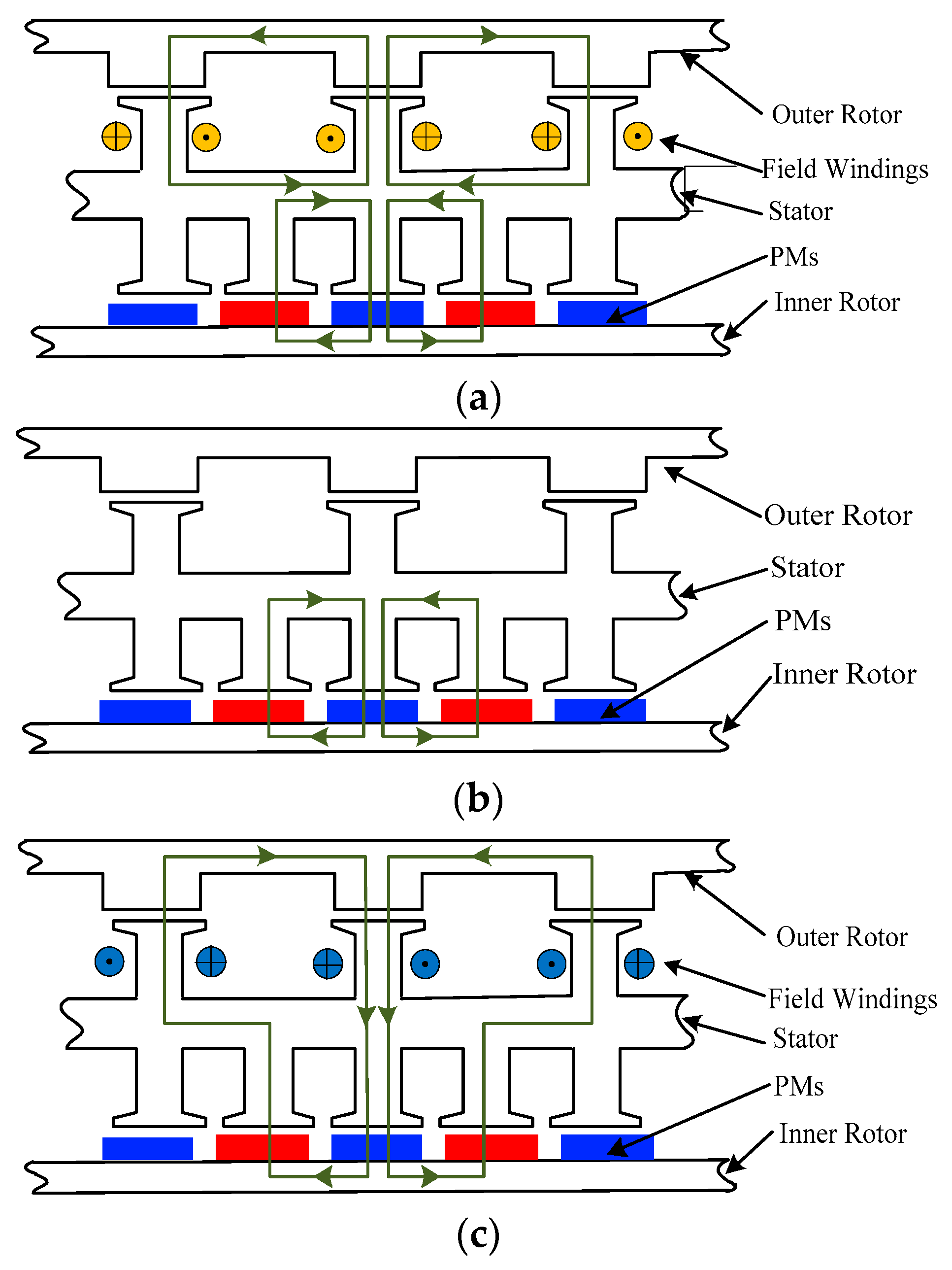
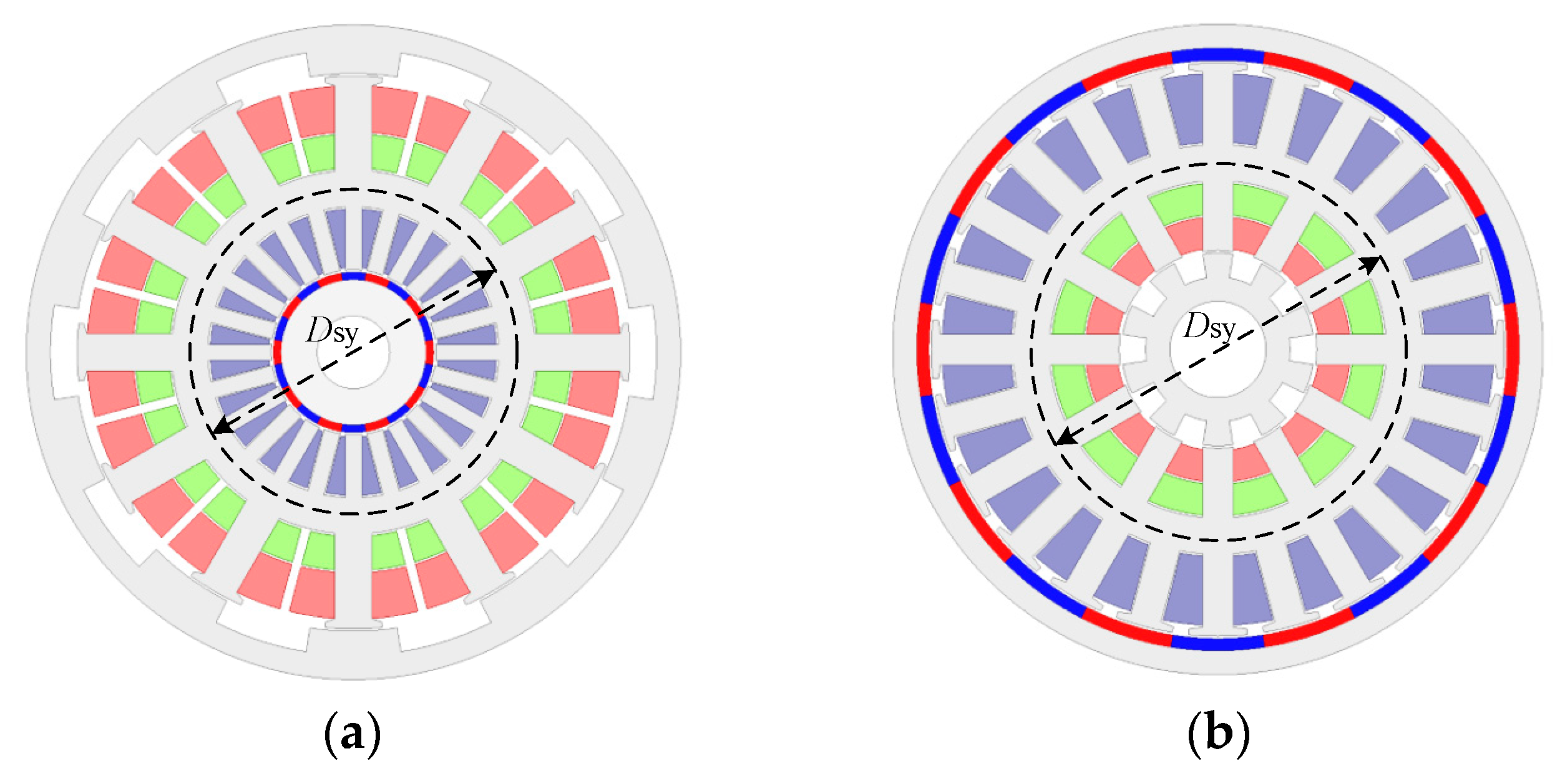
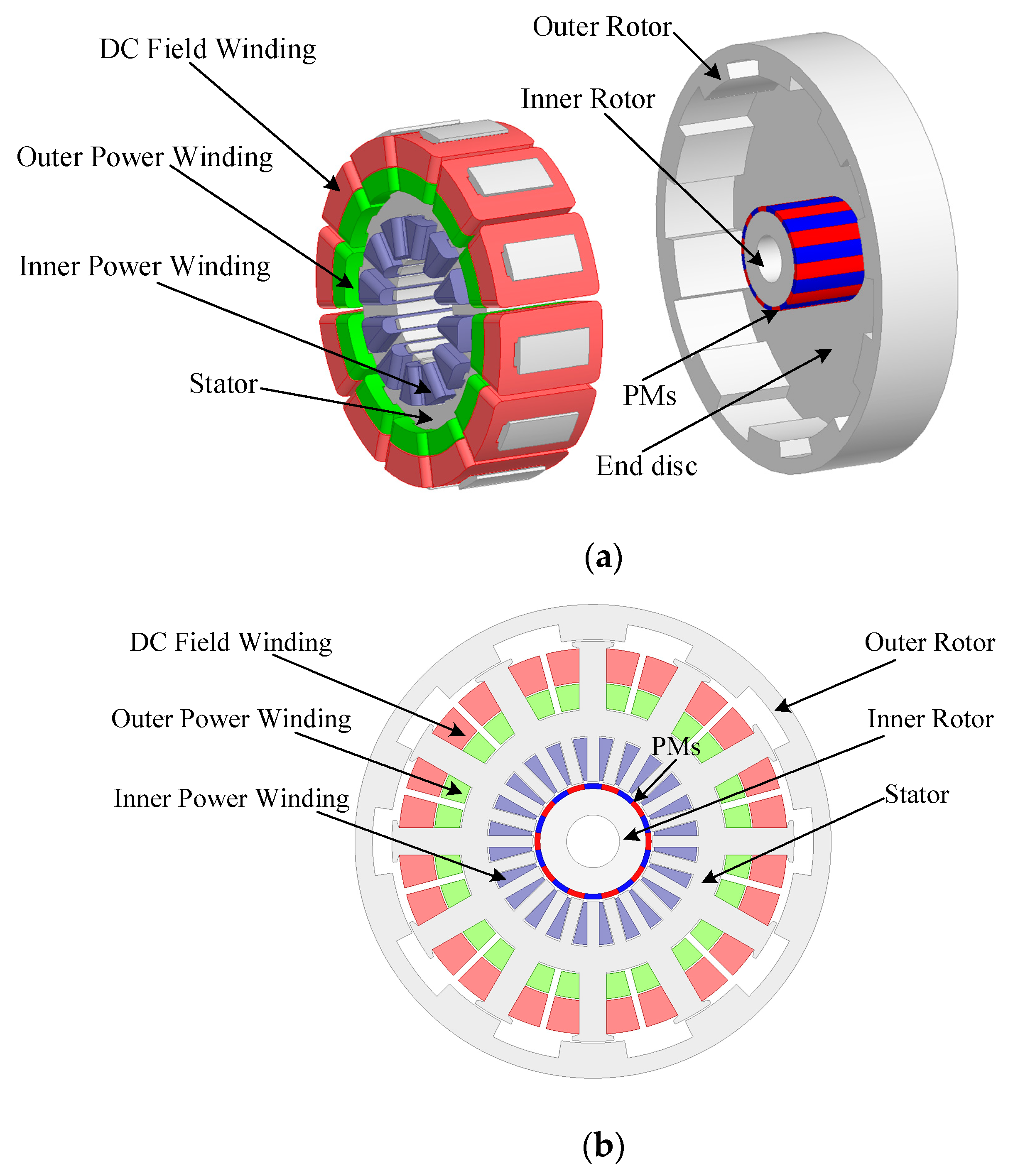
2.1. Machine Structure

The structure of the proposed DS-PHEM is presented in Figure 1. It adopts a double-rotor dual-structure construction, with PMs arranged on the inner rotor, and is mechanically connected with the outer salient-pole rotor by an end disc to form an integral rotor, thus realizing a torque boosting effect and power composition. A middle stator has 12 outer teeth, 24 inner teeth and a common yoke, and is sandwiched between these double rotors. Furthermore, to realize the flux regulation, DC field coils are introduced and identically wound on the stator outer teeth. By such an artificial configuration, two machine structures, a PMSM and a DC-excited doubly salient machine (DC-DSM), can be effectively integrated into a compact structure. Advantages of this design can be listed as:
  • A brushless structure is achieved since DC field winding is located at the stationary body, which ensures simple DC field current regulation and high reliability.
  • Two machine structures are integrated into a compact design, leading to a torque boost effect.
  • Two machine structures share a common stator yoke, which contributes to a decoupled and parallel magnetic circuit, thus, no demagnetization risk exists during DC field current regulation.
  • The power of two machine structures can be flexibly designed and combined, which can provide a theoretically unlimited constant power range at both motor and generator modes.

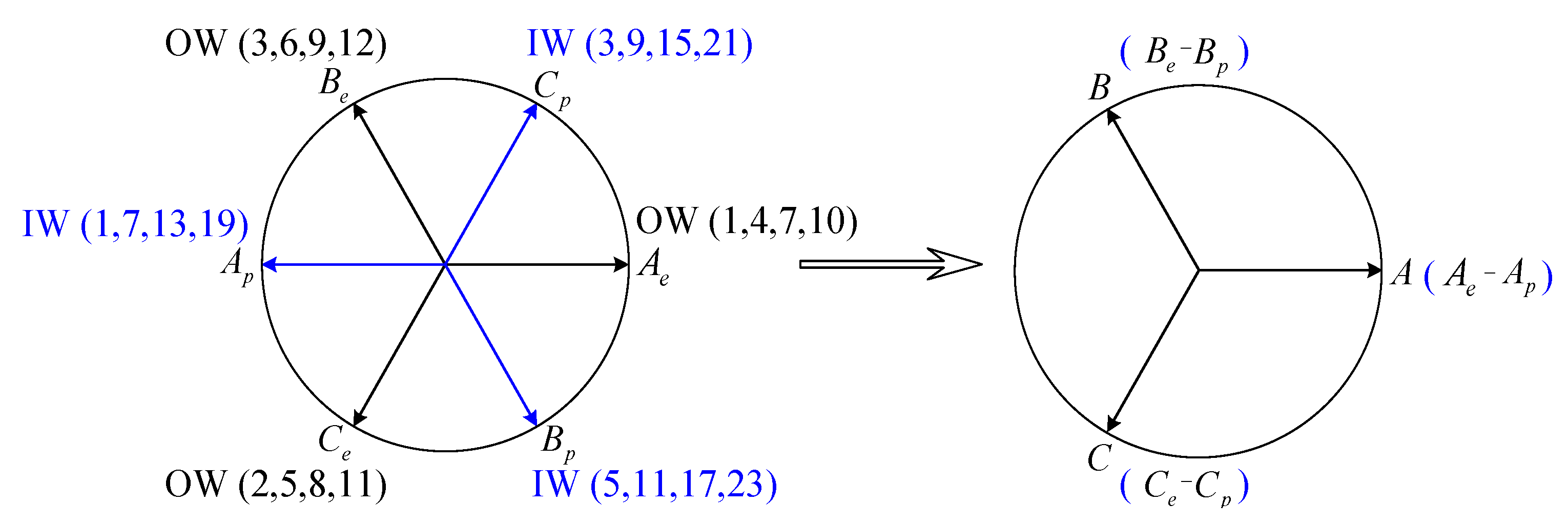
2.2. Electromagnetic Integration of Two Structures

There are two sets of power windings in the proposed machine: one is wound on the stator outer teeth to interact with the stationary DC field excitation, while the other is wound on the stator inner teeth to interact with rotating PM excitation. Furthermore, to realize effective electromagnetic integration, these two sets of power windings should be cascaded together to construct an integrated power winding. Figure 2 shows the corresponding coil phasors and connections of two power windings. To realize this effective cascade connection, the following three conditions should be satisfied.
Firstly, flux linkage of these two sets of power windings should have the same polarity variation. More specifically, both inner and outer flux linkage should be bipolar and sinusoidal, otherwise, if a bipolar armature flux is cascaded with a unipolar one, rich winding harmonics will be produced and thus iron loss will be serious. In the proposed machine, the inner armature winding interacts with a rotating PM magnetic field, and thus PM flux has the inherent bipolar characteristic and is also relatively easy to be sinusoidal. However, as for the outer armature winding, the flux linkage of each coil is usually biased and unipolar due to the stationary feature of DC field excitation. Therefore, in the proposed machine, a symmetrical arrangement of the outer field coils and armature coils is adopted to obtain a bipolar and sinusoidal outer flux linkage by using the effect of harmonic cancellation between complementary armature coils. In fact, distribution of outer power winding and DC field winding in the proposed design is similar to that in the existing variable flux reluctance machine [7], in which its mechanism to achieve bipolar and sinusoidal flux linkage has also been well discussed.
Secondly, flux linkage of inner and outer power windings must be kept in synchronous frequency. Therefore, the number of salient poles in the outer rotor should be equal to the PM pole-pair number of the inner rotor. In the proposed design, 10 rotor salient poles and 12 stator slots are adopted in the outer structure, while 10 pole-pair PMs and 24 stator slots are adopted in the inner structure.
Lastly, the phase angle of the two power windings should be the same or have 180° electrical angle difference. Therefore, the relative mechanical position between double rotors should be designed to meet this requirement. In the proposed machine, the d-axis position of the inner PM rotor is in line with that of the outer salient pole rotor.
Once the effective electromagnetic integration is achieved based on above three conditions, the total flux linkage produced by the proposed DS-PHEM can be simply defined as:
φ DS - PHEM = φ PMSM + φ DC - DSM
where φ PMSM is the flux component produced by the PMSM and φ DC - DSM is the flux component produced by the DC-DSM. Each flux component can be derived as:
φ = 4.44 D L T p h B n k w n
where D is the diameter of air gap circumference, L the stack length, T p h is the turn number of one phase, B n is the flux density of fundamental air gap harmonic, and k w n is winding factor. Further, the synthetic output voltage in DS-PHSM can be derived as:
e DS - PHEM = d dt ( φ PMSM + φ DC - DSM )
It is obvious that the output voltage is also the linear sum of that in the two structures.

2.3. Operation Principle of Flux Control

Figure 3 presents a schematic view of the no-load flux distribution with different DC field currents. To simply explain the operation principle of the proposed DS-PHEM, saturation is neglected in this discussion. As shown in Figure 3a, when a positive DC field current is applied, the stator outer teeth will have the opposite polarities against those of PMs mounted on the inner rotor. Consequently, the no-load flux produced by both structures will gather together and overlap in the common stator yoke, and thus the synthetic flux linkage achieves the maximum rated value. Figure 3b shows the flux path distribution with zero field current; it is apparent that the inner PM rotor is the only active excitation source and the DC field coils make no contribution to flux generation. Hence, the synthetic flux linkage will decrease to half of the rated value. Further, as shown in Figure 3c, when DC field winding is supplied by a negative DC field current, the magnetization polarity of stator outer teeth becomes the same as the aligned PMs, and thus the PM flux is in series with the DC field flux, passing through both the stator inner and outer teeth. In this case, the synthetic flux linkage can be greatly weakened. As discussed above, continuously adjustable flux linkage can be acquired by applying random field current changes between the positive and negative rated value.
It is obvious that the total flux distribution changes distinctly when the DC field current reverses its polarity, especially in the stator yoke part. However, it can be noticed that flux distribution in the stator outer teeth is not affected by the inner PMs, and similarly, DC field excitation also has little influence on the flux distribution in the stator inner teeth. Therefore, the flux linkage of two sets of power windings are decoupled and parallel. Due to this inherent feature, the proposed DS-PHEM essentially has a very wide range of flux adjustment, as well as no risk of PM demagnetization.

2.4. Design Considerations

In the proposed DS-PHEM, dual structures are combined by inner–outer configuration. In this case, an important design consideration is to define the relative location arrangement of two structures. As shown in Figure 4, the PMSM can be arranged at the inner side or outer side. However, considering the relatively poor excitation ability of DC field winding compared to that of PMs, it is recommended to arrange the PMSM at the inner side and the DC-DSM at the outer side, thus achieving a balanced power performance between the two structures. Meanwhile, since the two structures are connected by the common stator yoke, the power ratio of the two structures can be adjusted by tuning the diameter of the stator yoke, which influences both the power density and the flux regulation range. This will be evaluated in the following section.

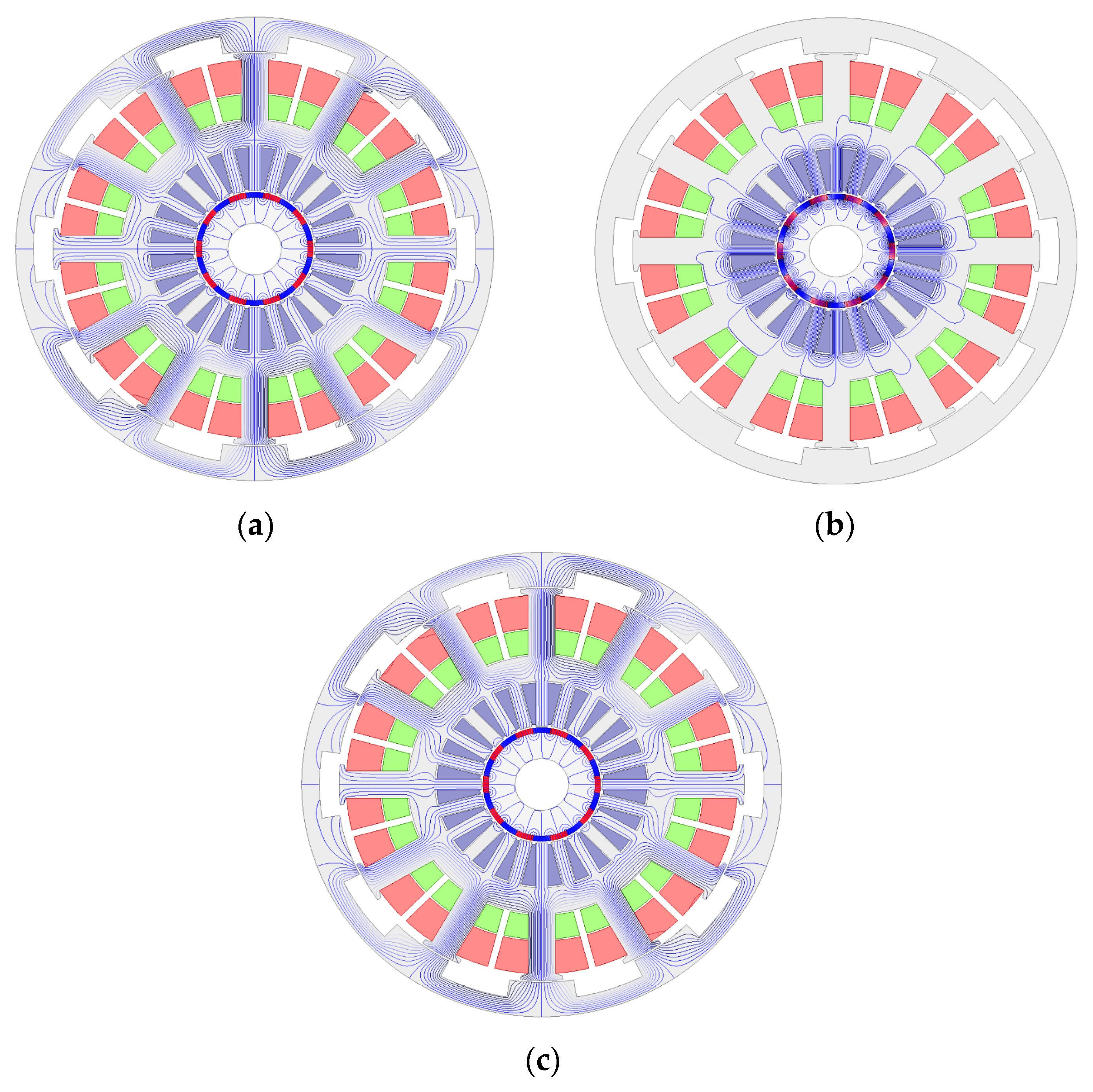
3. Finite Element Analysis

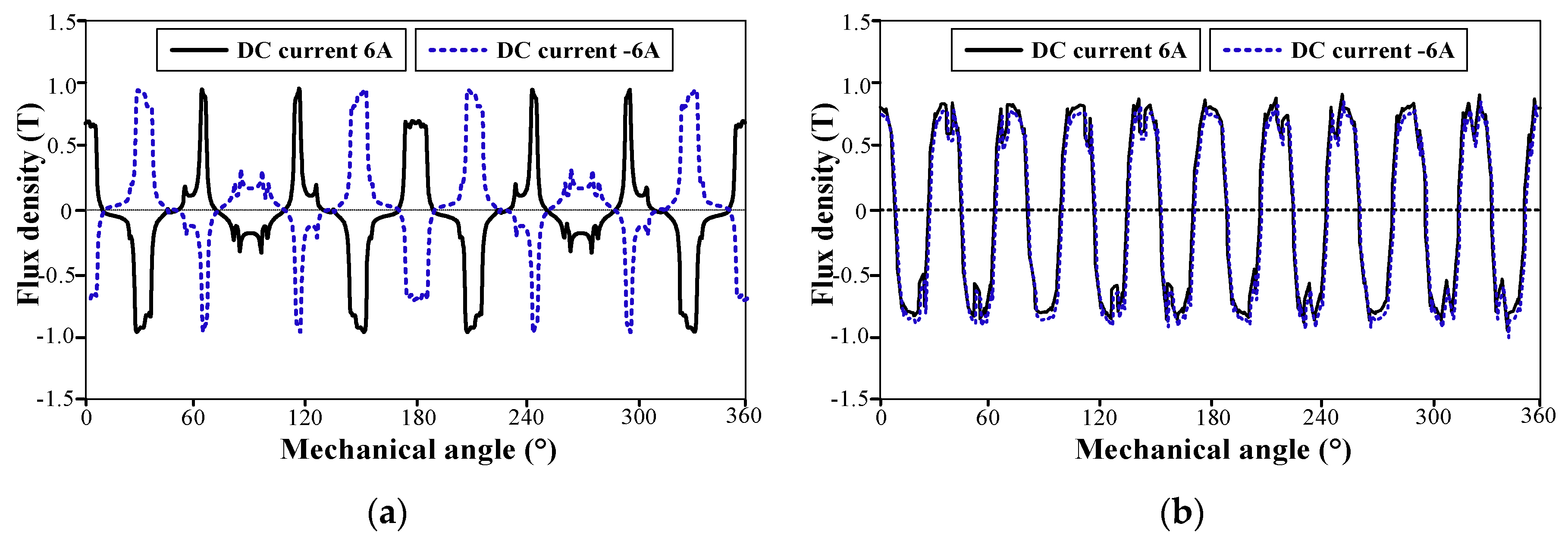
3.1. Flux Distribution

To verify the feasibility of the proposed DS-PHEM, a finite element model was built with the design parameters listed in Table 1. The major materials and specifications are also presented in Table 2. Further, the electromagnetic performance of the proposed DS-PHEM was fully evaluated. Figure 5 shows the no-load flux distribution with different DC field currents. It is shown that the calculated flux distribution is in accordance with the previous analysis in Section 2. The flux density of the outer air gap and inner air gap is further calculated and plotted in Figure 6a,b, respectively. We can see that, with a bipolar field current applied, the flux density in the outer airgap shows a bidirectional and symmetrical variation, while that in the inner airgap almost keeps constant. This agrees with its decoupled and parallel characteristic as discussed previously.

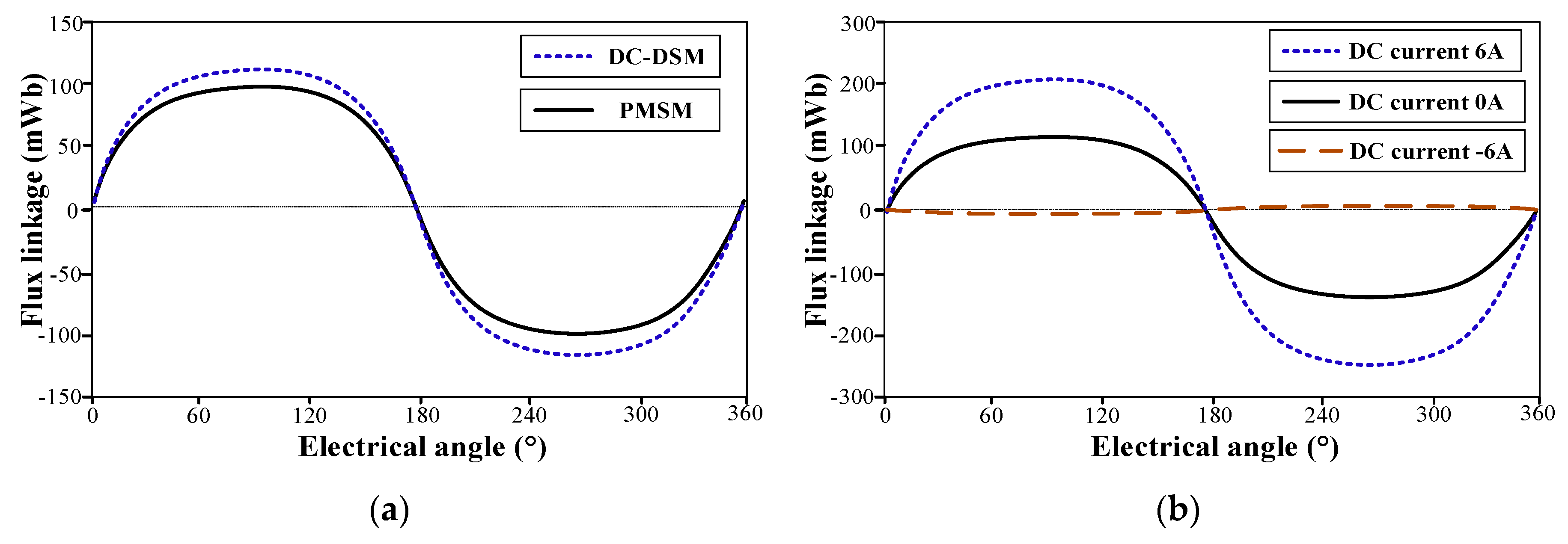
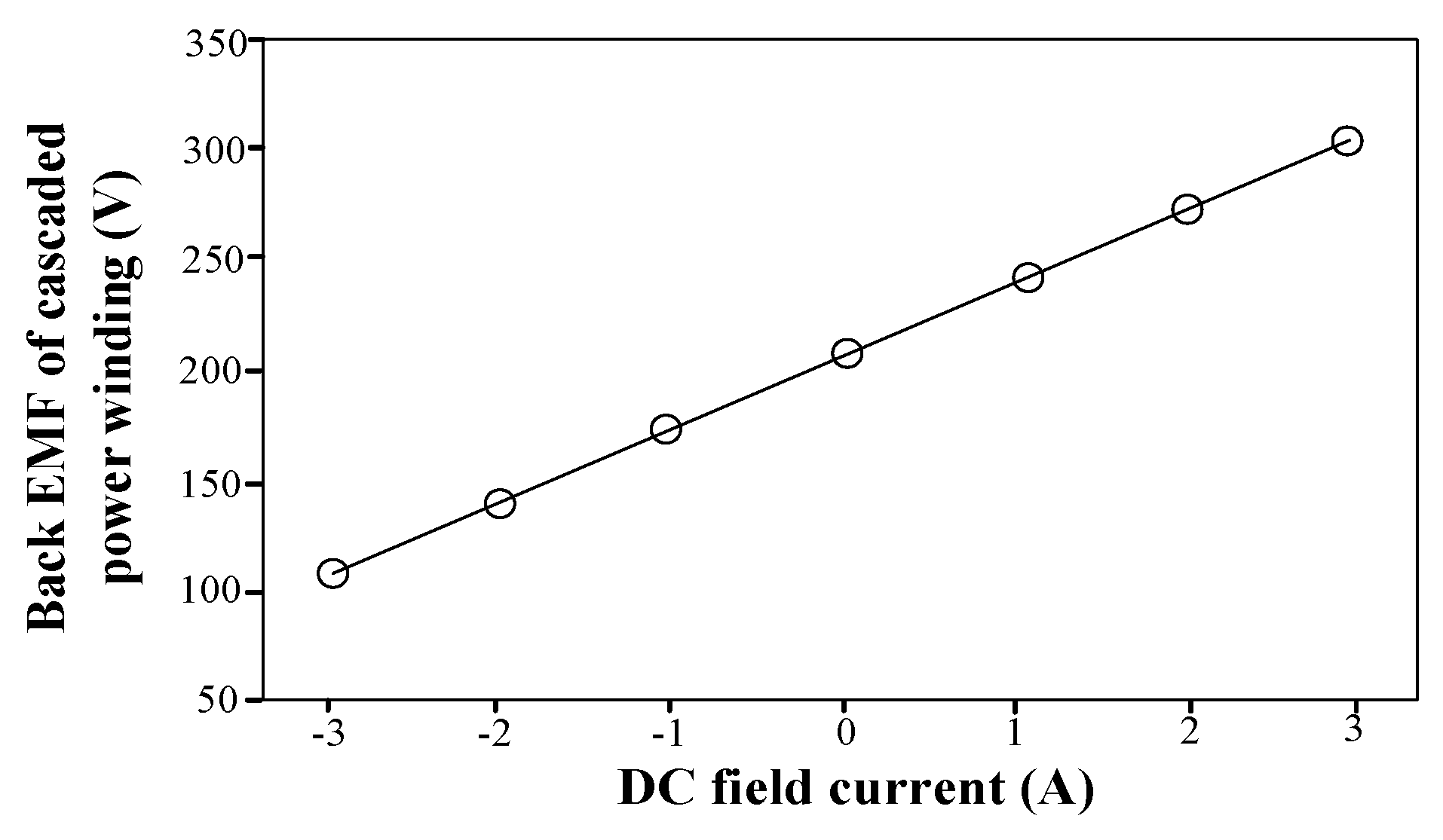
3.2. Flux Linkage and Back EMF

As mentioned above, in the proposed DS-PHEM, two sets of power windings in dual structures are cascaded together to form a single set of output winding. Therefore, to clearly investigate the flux characteristic, the flux linkage of each power winding is calculated and plotted in Figure 7a. It can be seen, with a 5 A positive DC field current applied, the flux linkage in the DC-DSM has the same phase position and a similar amplitude compared to that in the PMSM. Figure 7b shows the synthesis flux linkage of cascaded power winding with different DC field currents. It can be seen that with a 6 A positive DC field current applied, the synthesis flux linkage almost doubles compared to that in the DC-DSM or the PMSM. When the DC field current reverses its polarity and a 6 A negative DC field current is applied, the synthesis flux linkage almost decreases to zero. Therefore, an extremely wide field regulation range is achieved. The back-electromotive force (EMF) curve against different DC field currents is calculated and shown in Figure 8. Again, a wide voltage regulation range is achieved.

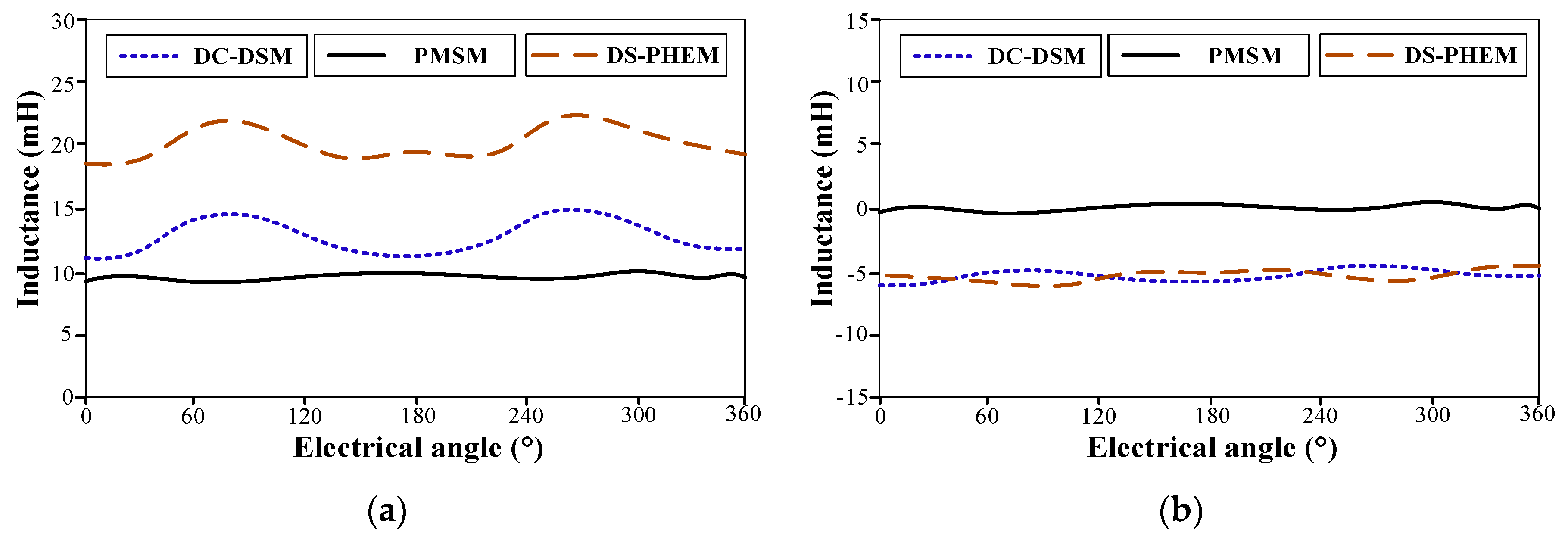
3.3. Inductance Characteristics

Figure 9 shows the inductance characteristic of a single-phase power winding. Due to a smaller equivalent air gap length, the inductance in the DS-DSM shows a larger average value compared to that in the PMSM. In addition, a relatively larger ripple of inductance exists in the DC-DSM caused by its rotor saliency effect. Mutual-inductance is also evaluated. It is shown the mutual inductance in the synthetic power winding is caused by the mutual inductance component in the DS-DSM.

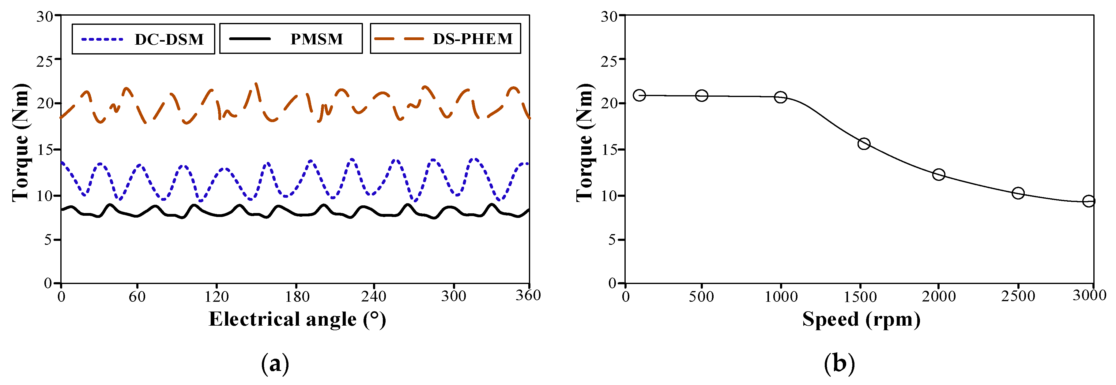
3.4. Torque Performance

Figure 10a presents the calculated steady torque with current density of 6 A/mm2. It can be seen the output torque can be easily regulated by applying different DC field currents and the torque ripple ratio is also acceptable. The torque–speed curve is calculated with the limit of constant DC bus voltage. As plotted in Figure 10b, in the low speed region, the DC field winding should be always be supplied by the maximum 6 A positive field current and this flux strengthening operation can boost the torque density. When the machine runs over 800 rpm, a flux weakening operation can be achieved by simply decreasing the DC field current. It is shown that when the DC field current decreases from positive 6 A to negative 6 A, the machine speed increases from 800 rpm to 3000 rpm, leading to a wide constant power range. It should be mentioned that the calculated constant power range is not infinite as expected and some factors, such as the armature reaction and saturation circumstance, account for this phenomenon.

4. Conclusions

A new brushless DS-PHEM is proposed in this paper. This machine theoretically can achieve a 100% field-weakening operation and corresponding infinite constant power range. The fault-tolerant de-excitation can be also expected from this machine topology when a short circuit occurs. The machine configuration and operating principles are illuminated in detail, with emphasis on some design criteria for effective electromagnetic integration. By using finite element analysis, the overall electromagnetic performance of the proposed machine is fully evaluated, and relevant results show the proposed machine has a wide range of flux control and speed regulation. Therefore, this machine could be a potential alternative for electric vehicle propulsion.

Author Contributions

X.Z. (Xiaodong Zhang) and X.Z. (Xing Zhao) designed the machine, analyzed the results and wrote the paper; S.N. provided the initial idea and helped to improve the manuscript.

Funding

This work was supported in part by the Research Grant Council of the Hong Kong Government under Project PolyU 15250916/16E and in part by the NSFC of China under Project 51707171.

Conflicts of Interest

The authors declare no conflict of interest.

References

  1. Han, K.J.; Cho, D.H.; Jung, H.K. Optimal core shape design for cogging torque reduction of BLDC motor using genetic algorithm. In Proceedings of the International Conference on Electric Machines and Drives, Sapporo, Japan, 9–12 May 1999; pp. 332–333. [Google Scholar]
  2. Zhao, X.; Niu, S. Design of a novel consequent-pole transverse-flux machine with improved permanent magnet utilization. IEEE Trans. Magn. 2017, 53, 1–5. [Google Scholar] [CrossRef]
  3. Potgieter, J.H.J.; Kamper, M.J. Torque and voltage quality in design optimization of low-cost non-overlap single layer winding permanent magnet wind generator. IEEE Trans. Ind. Electron. 2012, 59, 2147–2156. [Google Scholar] [CrossRef]
  4. Song, W.L.; Miller, T.J. Field-weakening performance of brushless synchronous AC motor drives. IEE Proc. Electr. Power Appl. 1994, 141, 331–340. [Google Scholar] [CrossRef]
  5. Zhao, X.; Niu, S. Investigation of a new hybrid excitation machine with auxiliary winding for energy recycling. IEEE Trans. Magn. 2017, 53, 1–5. [Google Scholar] [CrossRef]
  6. Wang, Q.; Niu, S. Overview of flux-controllable machines: Electrically excited machines, hybrid excited machines and memory machines. Renew. Sustain. Energy Rev. 2017, 68, 475–491. [Google Scholar] [CrossRef]
  7. Zhao, X.; Niu, S. Design and optimization of a novel slot-PM-assisted variable flux reluctance generator for hybrid electric vehicles. IEEE Trans. Energy Convers. 2018, 33, 2–11. [Google Scholar]
  8. Nasr, A.; Hlioui, S.; Gabsi, M.; Mairie, M.; Lalevee, D. Design optimization of a hybrid-excited flux-switching machine for aircraft safe DC power generation using a diode bridge rectifier. IEEE Trans. Ind. Electron. 2017, 64, 9896–9904. [Google Scholar] [CrossRef]
  9. Amara, Y.; Vido, L.; Gabsi, M. Hybrid excitation synchronous machines: Energy-efficient solution for vehicles propulsion. IEEE Trans. Veh. Technol. 2009, 58, 2137–2149. [Google Scholar] [CrossRef]
  10. Zhao, X.; Niu., S.; Fu, W. A new modular Relieving-DC-Saturation Vernier reluctance machine excited by zero sequence current for electric vehicle. IEEE Trans. Magn. 2019. [Google Scholar]
  11. Chau, K.T.; Chan, C.C.; Liu, C. Overview of permanent-magnet brushless drives for electric and hybrid electric vehicles. IEEE Trans. Ind. Electron. 2008, 55, 2246–2257. [Google Scholar] [CrossRef]
  12. Cheng, M.; Hua, W.; Zhang, J.; Zhao, W. Overview of stator-permanent magnet brushless machines. IEEE Trans. Ind. Electron. 2011, 58, 5087–5101. [Google Scholar] [CrossRef]
  13. Jian, L.; Shi, Y.; Liu, C.; Xu, G.; Chan, C.C. A novel dual-permanent-magnet-excited machine for low-speed large-torque applications. IEEE Trans. Magn. 2013, 49, 2381–2384. [Google Scholar] [CrossRef]
  14. Niu, S.; Ho, S.L.; Fu, W.N. A novel stator and rotor dual PM Vernier motor with space vector pulse width modulation. IEEE Trans. Magn. 2014, 50, 805–808. [Google Scholar] [CrossRef]
  15. Fodorean, D.; Djerdir, A. A double excited synchronous machine for direct drive application—Design and prototype tests. IEEE Trans. Energy Convers. 2007, 22, 656–665. [Google Scholar] [CrossRef]
  16. FCapponi, G.; de Donato, G.; Borocci, G.; Caricchi, F. Axial-flux hybrid-excitation synchronous machine: analysis design and experimental evaluation. IEEE Trans. Ind. Appl. 2014, 50, 31. [Google Scholar]
  17. Tapia, J.A.; Leonardi, F.; Lipo, T.A. Consequent-pole permanent magnet machine with extended field-weakening capability. IEEE Trans. Ind. Appl. 2003, 39, 1704–1709. [Google Scholar] [CrossRef]
  18. Zhang, Z.; Yan, Y.; Yang, S.; Bo, Z. Principle of operation and feature investigation of a new topology of hybrid excitation synchronous machine. IEEE Trans. Magn. 2008, 44, 2174–2180. [Google Scholar] [CrossRef]
  19. Liu, Y.; Zhang, Z.; Zhang, X. Design and optimization of hybrid excitation synchronous machines with magnetic shunting rotor for electric vehicle traction applications. IEEE Trans. Ind. Appl. 2017, 53, 5252–5261. [Google Scholar] [CrossRef]
  20. Liu, C.; Chau, K.T.; Jiang, J.Z. A permanent-magnet hybrid brushless integrated starter–generator for hybrid electric vehicles. IEEE Trans. Ind. Electron. 2010, 57, 4055–4064. [Google Scholar] [CrossRef]
  21. Zhao, X.; Niu, S. Design of a novel parallel-hybrid-excited Vernier reluctance machine with improved utilization of redundant winding harmonics. IEEE Trans. Ind. Electron. 2018, 65, 9056–9067. [Google Scholar] [CrossRef]
  22. Owen, R.L.; Zhu, Z.Q.; Jewell, G.W. Hybrid-excited flux-switching permanent-magnet machines with iron flux bridges. IEEE Trans. Magn. 2010, 46, 1726–1729. [Google Scholar] [CrossRef]
  23. Zhao, X.; Niu, S.; Ching, T.W. Design and analysis of a new brushless electrically excited claw-pole generator for hybrid electric vehicle. IEEE Trans. Magn. 2018, 54, 1–5. [Google Scholar] [CrossRef]
  24. Hua, H.; Zhu, Z.Q. Novel parallel hybrid excited machines with separate stators. IEEE Trans. Energy Convers. 2016, 31, 1212–1220. [Google Scholar] [CrossRef]
  25. Zhao, X.; Niu, S. Design and optimization of a new magnetic-geared pole-changing hybrid excitation machine. IEEE Trans. Ind. Electron. 2017, 64, 9943–9952. [Google Scholar] [CrossRef]
  26. Jang, D.K.; Chang, J.H. Design of a Vernier machine with PM on both sides of rotor and stator. IEEE Trans. Magn. 2014, 50, 877–880. [Google Scholar] [CrossRef]
  27. Wang, Q.; Niu, S.; Yang, L. Design optimization and comparative study of novel dual-PM excited machines. IEEE Trans. Ind. Electron. 2017, 64, 9924–9933. [Google Scholar] [CrossRef]
  28. Zhao, X.; Niu, S.; Fu, W. Design of a novel parallel-hybrid-excited dual-PM machine based on armature harmonics diversity for electric vehicle propulsion. IEEE Trans. Ind. Electron. 2018. [Google Scholar] [CrossRef]
  29. Wang, Q.; Niu, S. A novel hybrid-excited dual-PM machine with bidirectional flux modulation. IEEE Trans. Energy Convers. 2017, 32, 424–435. [Google Scholar] [CrossRef]
  30. Shi, Y.; Jian, L. A novel dual-permanent-magnet-excited machine with flux strengthening effect for low-speed large-torque applications. Energies 2018, 11, 153. [Google Scholar] [CrossRef]
Figure 1. Configuration of the proposed dual-structure parallel hybrid excitation machine (DS-PHEM): (a) 3D view; (b) 2D sectional view.
Energies 12 00338 g001
Figure 2. Coil phasors for integrating inner power winding and outer power winding. (OW refers to outer power winding, IW refers to inner power winding).
Energies 12 00338 g002
Figure 3. Schematic flux linkage distribution: (a) positive DC field current; (b) zero DC field current; (c) negative DC field current.
Energies 12 00338 g003
Figure 4. Arrangements of dual structures: (a) inner permanent magnet synchronous machine (PMSM) and outer DC-excited doubly salient machine (DC-DSM); (b) inner DC-DSM and outer PMSM.
Energies 12 00338 g004
Figure 5. No load flux distribution with: (a) 6 A positive DC field current; (b) zero DC field current; (c) 6 A negative DC field current.
Energies 12 00338 g005
Figure 6. No-load flux density along the air gap circumference: (a) outer air gap; (b) inner air gap.
Energies 12 00338 g006
Figure 7. No-load flux linkage: (a) single power winding; (b) cascaded power winding.
Energies 12 00338 g007
Figure 8. Back-EMF curve against different DC field currents.
Energies 12 00338 g008
Figure 9. Inductance characteristics: (a) self-inductance; (b) mutual-inductance.
Energies 12 00338 g009
Figure 10. (a) steady torque with 6 A/mm2 current density; (b) torque speed curves.
Energies 12 00338 g010
Table 1. Design parameters of the proposed DS-PHEM.
ParameterUnitValueParameterUnitValue
Outer diameter of outer rotormm270Outer diameter of stator yokemm152
Inner diameter of outer rotormm230Inner diameter of stator yokemm118
Number of rotor salient poles-10Outer diameter of stator inner teethmm68
Arc of rotor salient poles°7Number of stator inner teeth-24
Length of outer air gapmm1Coil number of inner power winding-80
Outer diameter of stator outer teethmm228Length of inner air gapmm1
Number of stator outer teethmm12Outer diameter of inner rotormm66
Coil number of outer power winding-120Inner diameter of inner rotormm30
Coil number of outer field winding-250Number of PM pole pairs-10
Table 2. Major materials and specifications.
PMMaterialNdFeB35
Remanence1.2 T
Coercive force915 kA/m
SteelMaterialMG19_24
Saturated flux density1.8 T
Mass density7650 kg/m3

