Article

Performance Evaluation of an Anti Gas-Channeling System (Asphalt-Rigid Particle-Xanthan Gum) Applied in High-Temperature and High-Salinity Fractured Reservoir

1
College of Chemistry and Chemical Engineering, Southwest Petroleum University, Chengdu 610500, China
2
State Key Laboratory of Molecular Engineering of Polymers, Fudan University, Shanghai 200433, China
3
State Key Laboratory of Oil and Gas Geology and Exploitation of Chengdu University of Technology, Chengdu 610500, China
4
Key Laboratory of Oilfield Chemistry, PetroChina, Beijing 100083, China
*
Author to whom correspondence should be addressed.
Energies 2019, 12(24), 4766; https://doi.org/10.3390/en12244766
Submission received: 15 November 2019 / Revised: 10 December 2019 / Accepted: 11 December 2019 / Published: 13 December 2019
(This article belongs to the Special Issue Enhanced Oil Recovery 2020)

Abstract

:
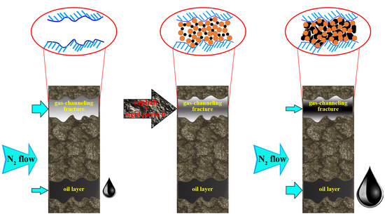
Asphalt and rigid particles have been chosen as the main blocking agent for solving the anti gas-channeling in high-temperature and high-salinity reservoirs. Particle size range and the concentration of suspending agent were firstly determined, and the influence factors on bonding effect between two materials in the high-temperature environment were then studied. An orthogonal experiment involving three factors (the content of rigid particles and asphalt, and softening point) and four levels was designed to investigate the impact order of the three factors on anti gas-channeling performance, and the optimization scheme has been identified. Results showed that the importance sequence of the factors was C rigid particles > C asphalt > softening point. By verifying the optimization scheme, the plugging ratio of this agent can reach more than 86.24% for 2 mm fractured core in high-temperature and high-salinity environments. The system was evenly distributed in the internal fractures, occupied the fractures completely, and had a certain height of accumulation. The micromorphology observations of the optimal scheme showed that the softened asphalt demonstrated its ‘amoeba’ characteristic and bonded with the surrounding rigid particles. The asphalt filled in the pore which was formed by bridging rigid particles to guarantee the blocking layer did not collapse or was carried by high-pressure N2-flow. This approach can potentially solve gas-channeling problems in reservoirs with serious environments.

Graphical Abstract

1. Introduction

Gas injection [1,2,3,4,5] is one of the important measures to enhance oil recovery in oilfields. However, due to the different degrees of heterogeneity in reservoirs caused by natural factors [6,7] and oilfield development later [8,9], and the influence of the adverse mobility ratio between the displacement phase and oil, the gas-channeling phenomenon is prone to occur in a stratum in the gas-injection process. Gas channeling reduces the sweep range of injected gas in a reservoir and causes adverse phenomena, such as low utilization rate of injected gas and even improper circulation, which ultimately influence the stimulation effect of gas flooding [10].
The conventional systems used to seal gas channeling include foam [11,12,13,14,15], polymer gel [16,17,18,19,20] and composite foam–gel systems [21,22,23,24]. To solve the problem of gas channeling and low blocking strength of existing foam systems during the development stage of multi-thermal fluid simulation in the Bohai oilfield, Han et al. [25] have prepared a kind of polymer gel with hydrolyzed polyacrylamide (HPAM) as the polymer agent and phenolic system as cross-linker. Yu et al. [26] adopt a new type of gas plugging agent to solve the problem of gas channeling in the steam stimulation horizontal wells. This low-cost and high-temperature resistant agent is a solution system and does not contain solid particles that use inorganic materials and organic materials as the inducing agent and surfactant as the stabilizer. Zhou et al. [27] combined modified starch strong-gel with ethylenediamine to create a new set of ethylenediamine solution that has water-like initial viscosity and were able to seal the fractures by forming a white solid and yellowish substance after reacting with CO2. Wang et al. [28] developed a preformed particle gel which responsive to CO2 (CO2-responsive gel). However, this new type of anti gas-channeling system still faced challenges including high-pressure gradient and long-term exposure to CO2. At the same time, the swelling times of CO2-responsive gel will decrease while the concentration of NaCl increased, which also reflects the problem of poor salinity-resistance of the gel. Hu [29] screened the formulation of the enhanced foam system with high-temperature and high-salinity resistance by using the Waring blender method. The enhanced foam can increase the flow resistance of the fluid in the matrix and fractures, and has fluidity control ability with the resistance factor of 5.09–38.66. By using starch as the main agent, Shi [30] developed a high-strength gel system which has high-strength and can effectively block the fractures in low-permeability cores. The laboratory fractured core-blocking experiment shows that before sealing, the flow rate of CO2 at the core outlet is 290 mL·min−1. After injecting the anti gas-channeling system into the core, the flow rate of CO2 can be reduced to a minimum of 35 mL·min−1, with a reduction of 87.93%, which expands the sweep region of CO2 flooding. Yang [31] studied the feasibility of three methods to inhibit CO2 gas channeling in microfractures (0.1 mm), namely, alternating water and gas flooding, CO2 flooding after small molecule organic amine plugging, and CO2 flooding after modified starch plugging. The results of laboratory core flow experiments show that the three methods can effectively inhibit CO2 gas channeling, and the time of CO2 gas channeling is delayed in different degrees. Liu [32] studied the effects of different methods of CO2 foam injection on the blocking ability of low-permeability fractured cores. The experimental results showed that CO2 foam can increase the flow resistance of the fluid in the fractured, which can effectively reduce the fluidity of displacement fluid, and the resistance factor is up to 46–80. Additionally, there is startup pressure in the fracture of CO2 foam, which affects the foam flow at the initial stage.
However, with oilfields gradually expanding to high-temperature and high-salinity reservoirs (T > 120 °C, Total salinity > 200 g·L−1), these gas-channeling inhibition agents exist poor chemical stability, which leads to an undesirable long-term anti-channeling performance. Take the polymer gel system as an example, which is one of the most widely used in preventing gas channeling. The main agent of gel used in the most oilfield is still acrylamide-based polymer. In a high-salinity environment, the intramolecular carboxyl charges of acrylamide on the main chain are shielded by metal ions (Na+, K+, Ca2+ and Mg2+, et al.), the polymer chains appear curled, and the salt-sensitivity effect will become more obvious with the increase of temperature. Due to the high shrinkage of molecular chains in high-temperature and high-salinity environments, the number of cross-linking sites exposed by polymer molecular chains has dropped sharply. Not only does the polymer gel have a weak gel strength, but also in the long-term high-temperature and high-salinity environment, the weak cross-linking state of the gel weaken the ability of gel network structure to bind water molecules, leading to the dehydration of the polymer gel, which lost the blocking effect to the channel. Therefore, for anti-channeling operations in a double-high (high-temperature and high-salinity) environment, materials that are immune to harsh conditions and have long-term performance stability should be considered. Asphalt is such an inert substance in which apparent viscosity is not affected by the formation water salinity, and it has a viscous flow state at a certain temperature that can effectively block the thief zone. At present, the profile control effect of asphalt on injection wells has been proved by laboratory experiments [33,34,35,36,37,38,39], and it was first used in Daqing oilfield and achieved good simulation results [33,34,35]. Wang [33] used a numerical simulation method to evaluate the displacement effect of asphalt profile control for well groups in a typical well area of Daqing oilfield and optimized the development mode. The numerical simulation results show that the asphalt profile control agent can effectively block the advantageous seepage channels which cannot be effectively blocked in the process of polymer flooding, expand the sweeping scope of water flooding, improve the development degree of middle and low permeability reservoirs, and realize the effective development of thick oil layers after polymer flooding. Li et al. [38] found that the asphalt profile control system after adjusting particle size and injection content can establish an even resistance in the high-permeability porous medium. For 2000 mD porous medium, when the asphalt content is 0.5% (particle size 0.1–0.3 μm), the residue resistance factor (RRF) was up to approximately 11, and the blocking rate to the core reached 91.57%. Xiao et al. [36] studied the feasibility of applying asphalt particles to block the water channeling layer after polymer flooding in Bohai oilfield. The results of core nuclear magnetic resonance (NMR) experiments show that by injecting asphalt particles into the thief zones, the resistance of the subsequent injected fluid to the high-permeability layer increased, the swept area of injected water increased, and the oil recovery of medium and small pores improved. Through numerical simulation of typical well groups in real reservoirs, the water cut of the reservoir decreased by 9.70%, and the oil production increase reaches 29.1 m3·day−1. Gao [39] simulated the oil layer condition of the P II-2 in the Lamadian oilfield in site construction. After profile control construction, the injection pressure of the injection well increased from 3.80 MPa to 8.16 MPa, rising by 4.36 MPa. After one month of construction, the surrounding connected oil wells were obviously effective, with an average daily increase of 7.60 t in a single well, a decrease of 1.8 m3 in daily fluid production, and a decrease of 5.30% in water cut in the well groups.
At present, the application of asphalt profile control is limited to the blocking of high-permeability zones in medium- and low-temperature reservoirs, and there are few reports on its application in the anti gas-channeling in high-temperature and high-salinity reservoirs, especially in fractured reservoirs with large fracture widths (a millimeter or even centimeter fracture). The anti-channeling system of single asphalt component has poor blocking effect under such conditions. Moreover, in the previous reports, the influence of the softening point and content of the asphalt on blocking effect was not included. Therefore, a new blocking agent (asphalt and rigid particle system) is introduced in this study to block gas channeling fractures in a double-high environment reservoirs. Asphalt and rigid particles are used as the main blocking agent, and a xanthan gum solution is adopted as the suspension to carry the main blocking agent to the target layers. The system takes advantage of the asphalt transformed into a high-viscous fluid in a high-temperature environment and bonded with the dispersed rigid particles into large clumps to block fractures. Under the conditions in this research (T = 130 °C, TDS = 223.07 g·L−1), the optimal anti gas-channeling system can achieve 86.24–91.02% blocking capability for cores with 2 mm network fractures, thus reducing the flux of injected gas in the fractures and promoting the diversion of gas flow. The system reduces the requirement for long-term chemical stability of the thickener in the stratum with a severe environment and only requires that the suspending agents carry the asphalt and rigid particles to the target layer. Moreover, the asphalt and rigid particles used in the system are simple and easy to obtain. The properties of the softening points of asphalt and the particle sizes of the two materials can be adjusted according to the actual stratum temperature and geometry conditions of fractures. The two main blocking materials are minimally affected by the harsh environment of the stratum and possess long-term anti-channeling performance.

2. Experimental Methodology

2.1. Materials and Instruments

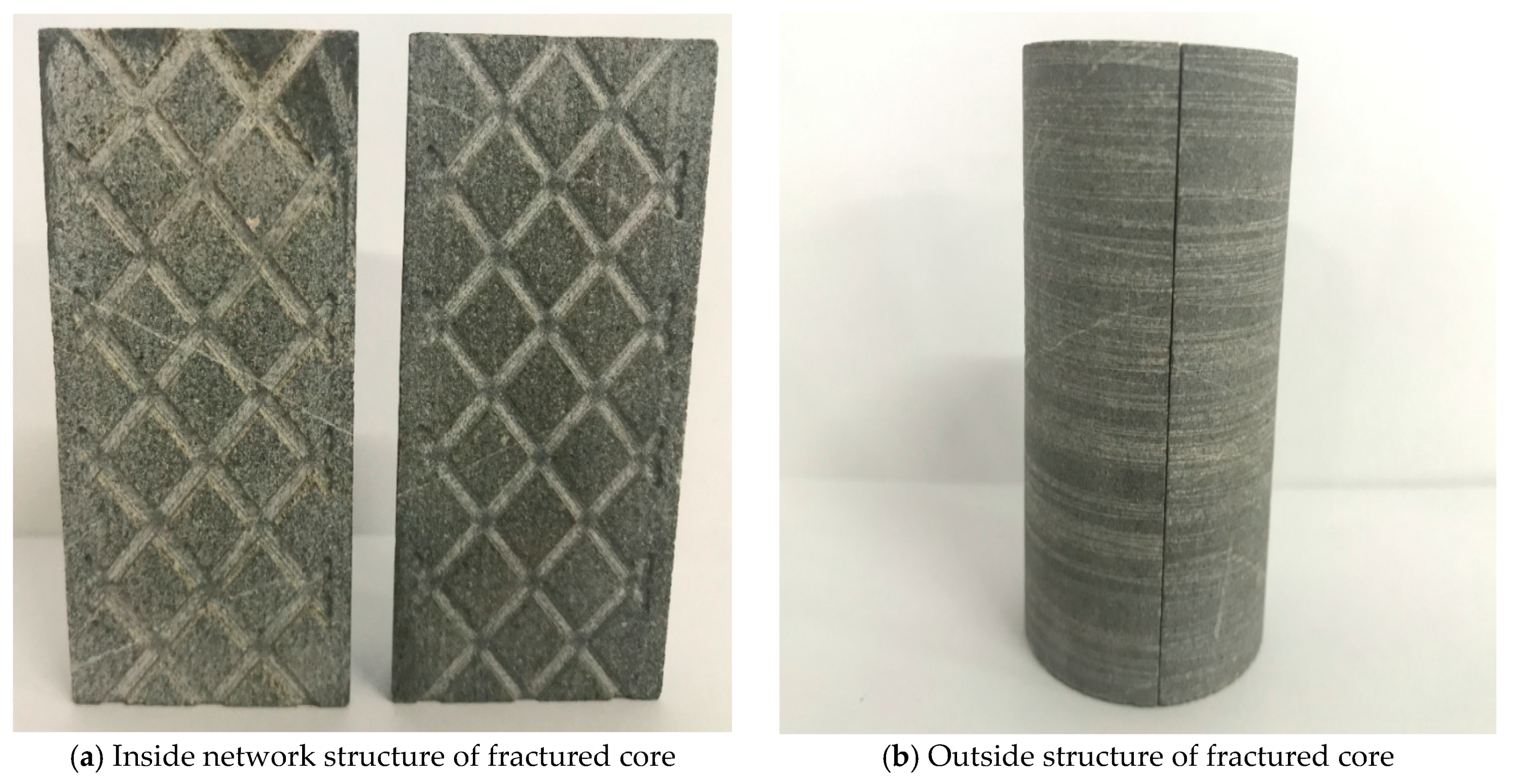
Materials: ① xanthan gum (dry powder), molecular weight 520 × 104, industrial grade, purity 99%, Inner Mongolia Fufeng biotechnology company, Hohhot, China. ② HPAM, molecular weight 2500 × 104, Daqing Refining and Chemical Company, Daqing, China. ③ AP-P4 (hydrophobic associated polymer), molecular weight 1200 × 104, Sichuan Guangya Polymer Chemical Co., Ltd, Chengdu, China. ④ petroleum asphalt: softening point are 60 °C, 90 °C, 105 °C, and 130 °C, Sinopec Qilu Petrochemical Company, the range of actual density is 0.98–1.08 g·cm−3, Zibo, China. ⑤ Rigid particles: ρ = 1.52 g·cm−3, Pmax = 40 MPa, Henan Jiekang environmental protection technology Company, Zhengzhou, China. (The physical map are shown in Figure 1) ⑥ The inorganic salts used to prepare simulated brine were bought from Chengdu Kelong chemical reagents factory, the components of simulated brine are shown in Table 1. The total salinity of brine is 223.07 g·L−1, and the density is 1.15 g·cm−3. ⑦ high-pressure N2. ⑧ simulated core: outcrop carbonate rock, the matrix permeability is very low and N2 does not seepage in it. The length of the core is 7.05 cm, the diameter is 3.81 cm. The core was cut into half, and the vertical section has been etched into network fractures by laser which used to research the distribution uniformity of an anti gas-channeling system in fractures, and the fractures are full symmetry. The width of fractures is 2 mm, the half-depth is 1 mm (total depth is 2 mm, the width was chosen according to the actual stratum fracture). The interval of fractures is 7 mm. The photograph of the simulated core shows in Figure 2, two cores were cemented with epoxy resin before the core-flooding experiment.
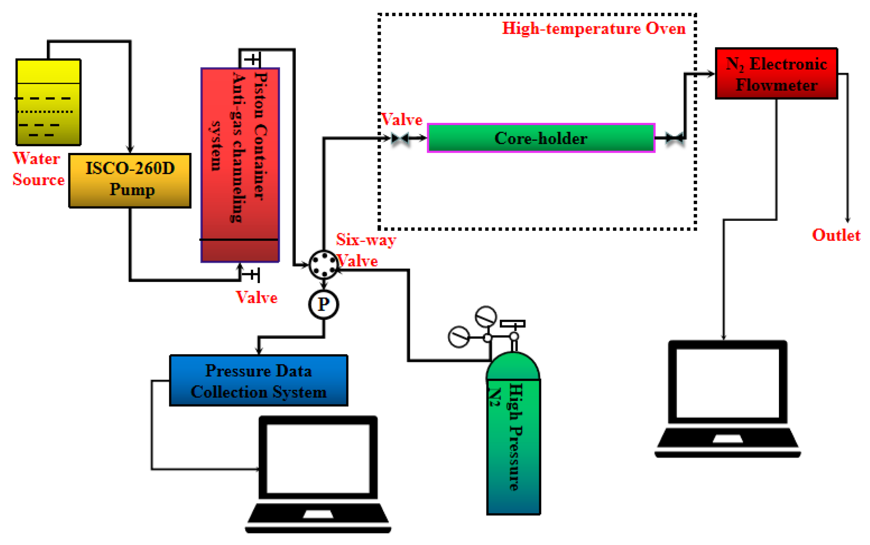
Instruments: Mastersizer 2000 laser granularity analyzer (Malvern Instruments Ltd., Malvern, UK), Brookfield CAP 2000 high-shear cone plate viscometer (AMETE Brookfield, Middleboro, USA), Haake MARS Ⅲ high-temperature and high-pressure rheometer (Thermo Fisher Scientific, Waltham, USA), FEI Quanta 450 environmental scanning electron microscopy (Thermo Fisher Scientific, Waltham, USA), EVOS no-eyepieces inverted fluorescence digital microscope (AMG, Seattle, USA), ISCO 260D syringe pump (0.01–107 mL·min−1, Pmax = 42 MPa, Teledyne ISCO, Lincoln, USA), MF 5712 electronic gas flowmeter (0–200 L·min−1, Siargo Ltd, Silicon Valley, USA), Core-holder (Tmax = 150 °C, Pmax = 15 MPa, D = 3.80 cm, Hai’an Petroleum scientific Research devices Co., Ltd, Hai’an, China), SG 83-1 dual automatic thermostat (Tmax = 300 °C, Hai’an Petroleum scientific Research devices Co., Ltd, Hai’an, China), Hydrothermal reactor (V = 25 mL, Tmax = 200 °C, Pmax = 5 MPa), Pressure sensor (0–5 MPa, accuracy grade 0.1% FS, Wika Ltd, Klingenburg, Germany), RW20 mechanical stirrer (0–1000 rpm, IKA, Baden-Wurttemberg, Germany). The flow chart of core displacement experiment shows in Figure 3.

2.2. Preparation of the Temperature- and Salinity-Resistance Anti Gas-Channeling System

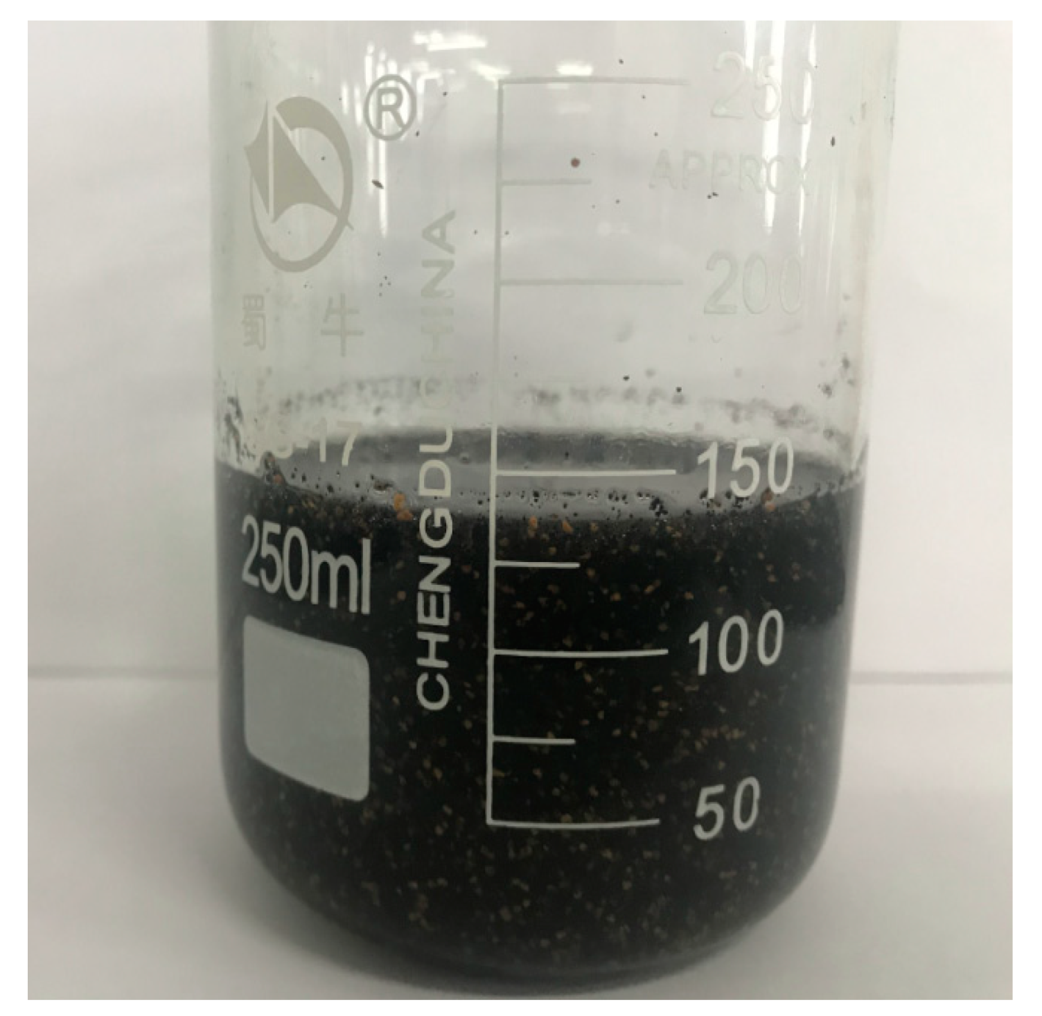
Simulated brine was obtained at a certain volume, and the stirrer was adjusted to 500 rpm. A certain amount of thickener was added to the spiral arm, and a certain amount and mesh of asphalt and rigid particles were added to the solution gradually after the dry powder was dissolved completely (approximately 1 h). After the asphalt and rigid particles were uniformly dispersed in the thickener solution, the temperature- and salinity-resistant anti-channeling system was obtained. Figure 4 presents the anti-channeling system adopted in this work.

2.3. Screening and Determination of Asphalt and Rigid Particle Sizes

According to the “1/3 bridging rules” introduced by Abrams [40,41,42], when the filling particle size (d*) is larger than 1/3 of the average diameter of stratum pore throat (d), the filling particles block at the entrance, and the filtrate invades the rock interior. When 1/7 d < d* < 1/3 d, the blocking system is bridged into the pores and forms a shielding zone. When d* < 1/7 d, the system passes through the pores without plugging. Therefore, assuming that the asphalt and rigid particles are rigid pellets, the particle size should be 1/7–1/3 of fracture d (1–2 mm) for screening. Moreover, the injection problem should be considered. In this work, the minimum size is 1 mm, thus, the range of particle size is approximately 143–333 μm.
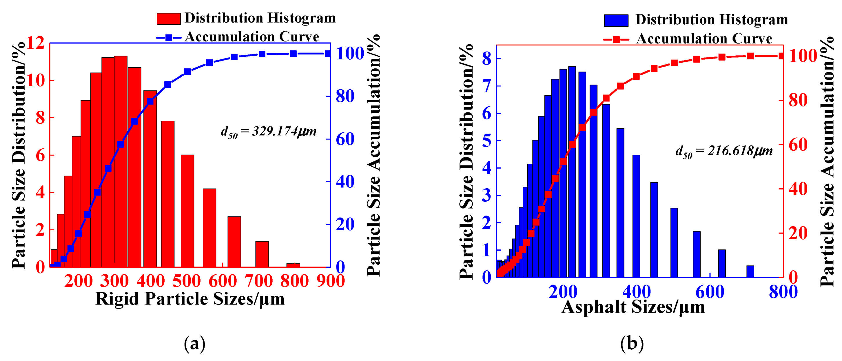
The bridging rigid particles were screened with 55- and 110-mesh sample sieves. Unlike rigid particles, asphalt particles are softened in high-temperature environments and bond with one another, thus exhibiting “amoeba” characteristics and the capability to match the pores automatically. Therefore, the particle size of asphalt just needs to meet the requirements of injectivity. Furthermore, the particle size distribution of asphalt and rigid particles after screening should be determined for quality control. The particle size distribution was measured with a Mastersizer 2000 laser granularity analyzer, and the results are shown in Figure 5. The median particle diameter (d50) of the rigid particles was 329.174 μm, which is close to that of the 1/3 bridging size. The d50 of the asphalt particle was 216.618 μm, which satisfies the injectivity requirement.

2.4. Asphalt Viscosity in High Temperature and Performance of Bonding with Rigid Particles

2.4.1. Apparent Viscosity of Different Softening Points of Asphalts and High-Temperature Aging Properties

A Brookfield CAP2000 high-shear cone plate viscometer was utilized to measure the apparent viscosity of four kinds of petroleum asphalt at 130 °C. The rotation speed of the cone plate was 6 rpm and corresponded to the shear rate of 17.7 s−1. At the same time, the asphalt with four different softening points was placed in an oven at 130 °C. The apparent viscosity was measured at 5 days, 10 days, 15 days, 20 days, 25 days and 30 days, respectively.

2.4.2. Properties of Asphalt-Bonded Rigid Particles

Equal masses of asphalt and rigid particles were mixed (both particle sizes were similar to those in Section 2.3). Then, the mixed particles were added to a high-temperature reactor. After 48 h, the mixed particles were removed from the oven (130 °C), and the performance of the asphalt bonded with rigid particles was observed.
The results show the bonding effect of asphalt and rigid particles in the absence of a dispersion medium. However, the asphalt and rigid particles were dispersed in a xanthan gum solution in a suspension state in the actual injection process. Given the distance between asphalt and rigid particles in the dispersion medium, the bonding performance is expected to change. Therefore, on the basis of the above study on bonding performance, the bonding properties of the two materials in dispersed state under the influence of different factors must be investigated. To further explore the influence of different factors on the bonding effect of particles, this study adopted a laser granularity analyzer to investigate the influence of the content of asphalt and rigid particles and the asphalt softening points on the degree of particle size change before and after bonding. The specific arrangements are as follows:
  • Influence of asphalt content on the bonding effect: The asphalt softening point was 105 °C, the rigid particle content was 8 wt%, and the asphalt contents were 2 wt%, 4 wt%, 6 wt%, and 8 wt%.
  • Influence of rigid particle content on the bonding effect: The asphalt softening point was 105 °C, the asphalt content was 8 wt%, and the rigid particle contents were 2 wt%, 4 wt%, 6 wt% and 8 wt%.
  • Influence of asphalt softening point on the bonding effect: The content of asphalt and rigid particles was 8 wt%, and the asphalt softening points were 60 °C, 90 °C, 105 °C, and 130 °C.
The anti gas-channeling system under the corresponding conditions was prepared according to the experimental arrangement above and the preparation method mentioned in Section 2.2. After preparing the system, the particle size distribution (PSD) was measured with a laser granularity analyzer. Then, the system was added to a 25 mL hydrothermal reactor, and the reactor was placed in an oven at 130 °C for 48 h before being taken out. After cooling to room temperature, PSD was measured again to observe the changes in the particle size of the anti gas-channeling system before and after heating.

2.5. Optimization of Thickener Type and Concentration

2.5.1. Selection of Thickener Types

(1) The solubility of thickener: HPAM is the hydrolyzed product of PAM (polyacrylamide). Due to the Coulomb repulsion, the carboxylic acid groups on the molecular chain of HPAM make the molecular chain stretch in aqueous solution, which increases the hydrodynamic radius of the polymer molecular chains, and makes its thickening property higher than PAM. AP-P4, a hydrophobic associated polymer, is modified by adding a little amount of hydrophobic groups (<1 mol%) on the basis of HPAM. Its temperature- and salinity-resistant properties are significantly improved compared with those of HPAM and have been applied in the oilfield [43,44,45,46]. However, the salinity of the prepared water used in this paper is as high as 223.07 g·L−1, and the hydrophobic groups contained in its molecular structure will affect its solubility. Therefore, before studying the rheology of thickeners, it is necessary to study the solubility of three thickeners in high-salinity brine.
Five 250 mL beakers were taken to add 100 mL simulated brine, and the rotation speed was adjusted to 500 rpm. 0.10 g, 0.20 g, 0.30 g, 0.40 g and 0.50 g of HPAM dry powder were added to the vortex arm of simulated brine, and the HPAM aqueous solution with a concentration of 1000 mg·L−1, 2000 mg·L−1, 3000 mg·L−1, 4000 mg·L−1 and 5000 mg·L−1 was prepared, respectively. The solubility was observed after stirring for 12 h. Aqueous solution of AP-P4 and xanthan gum was prepared as above.
(2) Steady-state rheological property of thickener in high-temperature: after the preliminary screening of the solubility of three thickeners in high-salinity brine, it is necessary to study the thickening properties of thickeners to determine whether they can meet the requirements of carrying asphalt and rigid particles into the target stratum. In this paper, Haake MARS Ⅲ high-temperature and high-pressure rheometers were adopted to study the thickening capability of three thickeners in high-temperature and high-salinity environments. The test concentrations were 1000 mg·L−1, 2000 mg·L−1, 3000 mg·L−1, 4000 mg·L−1 and 5000 mg·L−1. The shear rate was 0.01–100 s−1, the test temperature was 130 °C, and the CCB26 dual-cylinder test system was adopted in this research.
(3) Long-term thickening capability of thickener: the thickener needs to carrying the asphalt and rigid particles to the depth of the stratum to complete the blocking task. Therefore, in addition to meeting the requirements of solubility and thickening, the thickener still needs to meet the performance of viscosity-retention in a high-temperature environment for a certain period. The 50 mL thickener aqueous solution was added to the hydrothermal reactor in an oven at 130 °C, and taken out in 0 days, 2 days, 4 days, 6 days and 8 days. Using Haake MARS Ⅲ high-temperature and high-pressure rheometers determined the apparent viscosity of thickeners, the test concentrations were 1000 mg·L−1, 2000 mg·L−1, 3000 mg·L−1, 4000 mg·L−1 and 5000 mg·L−1. The shear rate was 7.34 s−1, the test system ibid.

2.5.2. Optimization of Suspending Agent Concentration

According to Section 2.1, ρ asphalt < ρ brine < ρ rigid particles, which follows Stocks sedimentation law, that is, the xanthan gum solution can stably suspend asphalt powder. Given that the density of rigid particles is obviously higher than that of simulated brine, the xanthan gum solution can only depend on its viscosity to suspend the rigid particles. The xanthan gum solution was prepared according to Section 2.2 and 2 wt% rigid particles were added to the solution at a concentration range of 0.1–0.6 wt%. The suspension performance at room temperature was observed (T = 25 °C).
The suspension capability at high-temperature was also investigated on the basis of room temperature. A xanthan gum solution with 2 wt% rigid particles was added to the hydrothermal reactor, and aging was performed in an oven (T = 130 °C). Then, the samples were taken out of the reactor at 0 h to 28 h (the time interval was 4 h, and the suspension performance at different times was observed.

2.6. Research on Anti Gas-Channeling Performance of the Asphalt Bonding System

2.6.1. Optimization of Maximum Injection Concentration

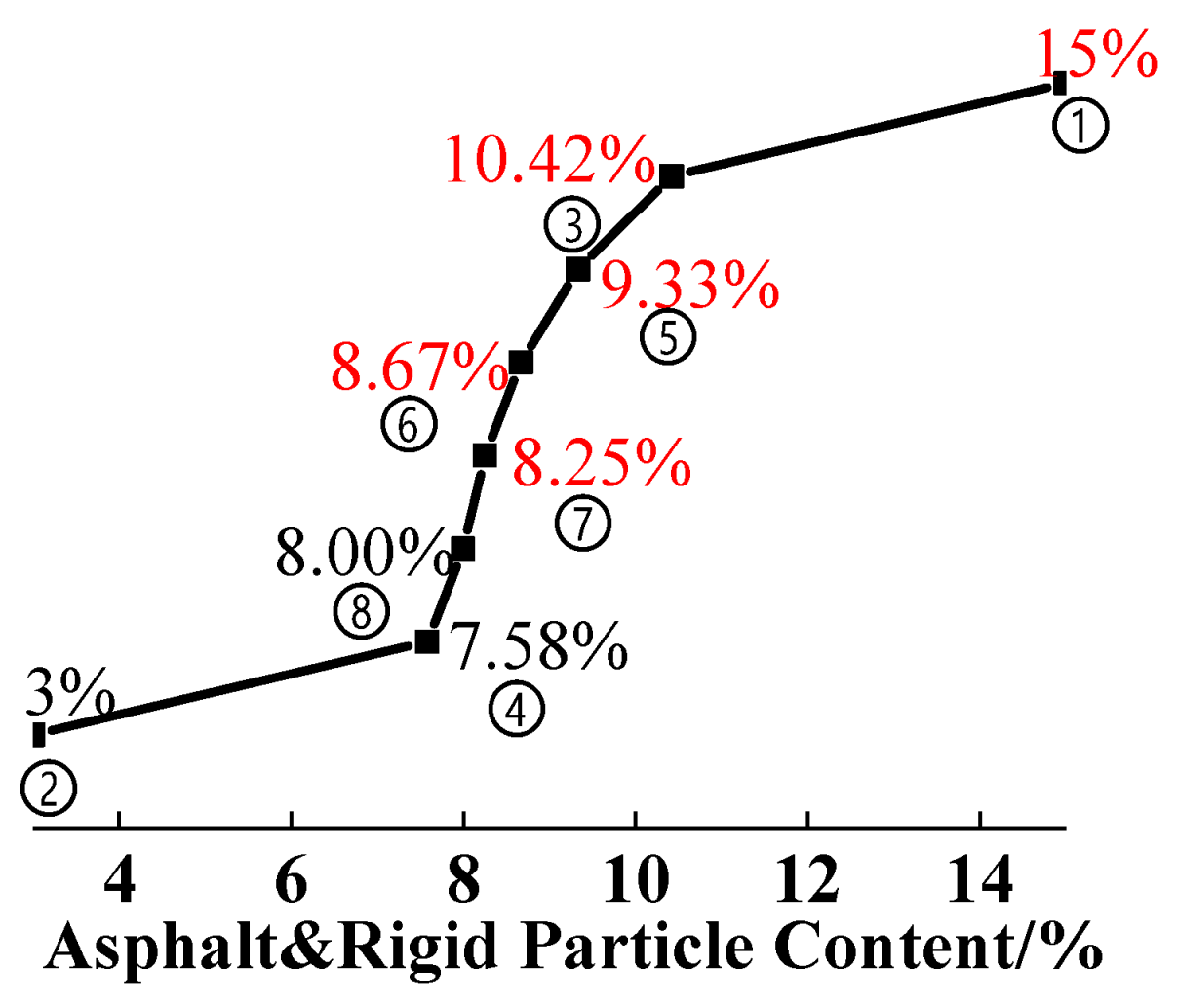
The maximum concentration of asphalt and rigid particles must be determined before investigating the factors that influence the blocking performance of the anti gas-channeling system. This study used the golden section algorithm [47,48,49,50] to solve this problem. Different mass concentrations of asphalt and rigid particles (masphalt:mrigid particles = 1:1) were prepared and core-flooding experiments were performed to study the system injectivity and optimize the maximum injection concentration continuously according to the golden section algorithm. The specific segmentation process was as follows. First, two concentrations, X1 and X2 (X2 > X1), were defined empirically, and the injectivity of the two concentrations was evaluated. If X1 meets the injectivity and X2 does not, then two groups of experimental points, X3 and X4, will be calculated according to the golden section algorithm. The calculation formulas are shown in Equations (1) and (2). Second, the injectivity of X3 and X4 was further tested: the golden section was still used between X3 and X4 to optimize the maximum injection concentration gradually.
X 3 = X 2 ( X 2 X 1 ) ( 5 1 ) 2
X 4 = X 1 + ( X 2 X 1 ) ( 5 1 ) 2

2.6.2. Distribution of Solid Particles in Xanthan Gum Solution

In this study, the state of suspended solid particles in the xanthan gum solution was observed with an EVOS no-eyepiece inverted fluorescence digital microscope. Compared with scanning electron microscopy (SEM), this approach can be used to observe a broader vision field and has an advantage in sample preparation. SEM needs to apply a vacuum sublimate liquid after freezing the sample with liquid N2, which is not conducive to observing the distribution of solid particles in the liquid. An optical microscope can be used to observe the samples in their original state with little influence system properties.

2.6.3. Investigation of Anti Gas-Channeling Performance and the Influencing Factors

The concentrations of rigid particles, asphalt, and its softening point must be optimized after determining the particle size of rigid particles and asphalt. This work adopted the orthogonal experiment method to study the importance sequence of the above three factors of blocking performance and obtain the optimal scheme. The designed factor levels are shown in Table 2, and the experimental grouping is shown in Table 3.
The steps of the core displacement experiment were as follows:
  • Fill the simulated core that has been cemented well to the core-holder and use a hand pump to exert a confining pressure of 5 MPa. High-pressure N2 was used as the air source for displacement, and an electronic flowmeter was utilized to measure the N2 velocity (v0, L·min−1) under different gas-flooding pressures at the tail end of the core-holder. The outlet flow rate of N2 was measured three times and the mean value was calculated, the same below (See the supplementary materials Tables S1 and S2 for detailed data).
  • Inject the anti gas-channeling system at 0.25 mL·min−1 until the tail end of the core-holder flows out of the system. Close the inlet and outlet valves of the core holder, and perform aging at a high-temperature for 48 h.
  • Open the inlet and outlet valves and displace them by N2. Measure the N2 velocity again (v1, L·min−1), and obtain the data on blocking performance.
The core flow experiment was performed in an oven at 130 °C. To investigate the anti-channeling performance in detail, this research used two displacement pressures, namely 0.25 and 1 MPa to measure the blocking performance at different pressures. The blocking ratio (W) was calculated using Equation (3) [51,52,53], which expresses the decrease in gas velocity through the fractured core before (v0) and after blocking (v1).
W = 1 v 1 v 0

2.6.4. Research of Anti Gas-Channeling Performance for Long Term

After obtaining the optimum formulation through the orthogonal experiment, the long-term anti gas-channeling performance of the system should be studied. The experimental flow chart in Figure 2 was also adopted, and the experimental steps were the same as those in Section 2.6.3. The core that has been injected into the anti gas-channeling system is placed in the core-holder and aged in an oven with 130 °C for 30 days. The anti gas-channeling performance of the system was measured at 5 days, 10 days, 15 days, 20 days, 25 days and 30 days.

2.7. Observation of Plugging Zone Micromorphology in the Fracture Interior

After completing the anti gas-channeling experiment of the optimal scheme, the simulated core was cut open, and the asphalt–rigid particles system inside the fracture was taken out. The micromorphology of the plugging zone was observed by environmental scanning electron microscopy (ESEM) to analyze the bonding effect of asphalt on the rigid particles. The acceleration voltage was 20 kV, and the diameter of the electron beam spot was 1~10 nm.

3. Results and Discussion

3.1. Bonding Performance of Asphalt in High Temperature

3.1.1. Apparent Viscosity of Asphalt in High Temperature

The viscosity of each asphalt in different softening points is shown in Figure 6a. The apparent viscosity at 130 °C increased with the petroleum asphalt softening point. When the softening point increased from 60 °C to 105 °C, the viscosity increased from 3019 mPa·s to 8561 mPa·s. The viscosity only increased to 9561 mPa·s when the asphalt softening point rose to 120 °C: the viscosity growth rate was slow in this softening point range. The viscosity of the four kinds of asphalt can meet the requirements of bonded rigid particles. Theoretically, the higher the asphalt viscosity was, the better the bonding effect of rigid particles. However, in the actual blocking process, the asphalt should be firmly bonded to the rigid particles, have a certain fluidity after softening at high temperatures, and show its “amoeba” characteristics to fill the pores in the surroundings formed by bridging particles. The plugging zone must be thickened, and the blocking performance must be enhanced. Hence, the viscosity test cannot be used alone to select the type of asphalt.
Moreover, the change of apparent viscosity of asphalt with different softening points under high-temperature and different aging time is shown in Figure 6b. The apparent viscosity of asphalt with different softening points does not fluctuate significantly under high-temperature conditions. The physical and chemical properties of asphalt at 130 °C are stable, which can guarantee the long-term bonding effect to the rigid particles, and then maintain the blocking strength of the anti gas-channeling system for the fractured channel.

3.1.2. Bonding Performance of Asphalt and its Influencing Factors

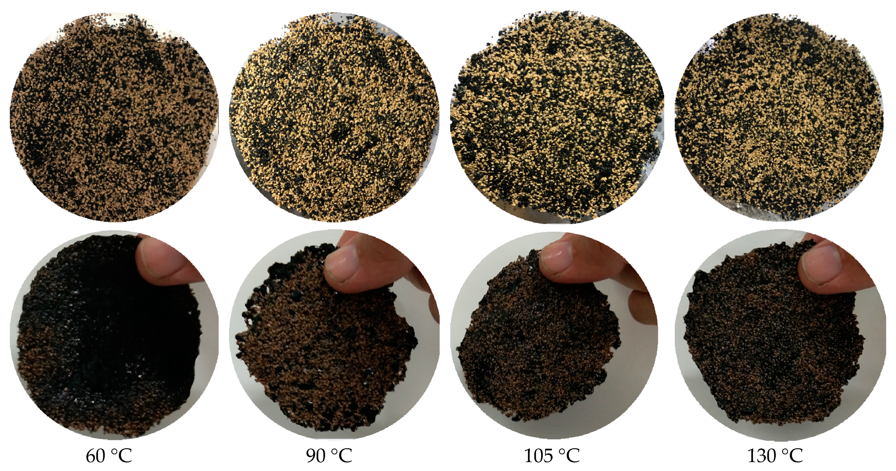
One of the most important properties of asphalt, which is the bonding material in the anti gas-channeling system, is its capacity to bond with rigid particles. In this work, asphalt powder was blended with rigid particles, and the bonding effect of asphalt on the rigid particles was observed. The experimental effect is shown in Figure 7. The comparison of the morphologies before and after bonding indicating that the asphalt and rigid particles before bonding were both in powder form, which could only be observed from a horizontal position (the top image). After bonding by asphalt at a high temperature, the asphalt-rigid particles cake could be placed vertically (the bottom image), and no dropping of asphalt or rigid particles occurred. The asphalt in different softening points showed a good bonding capability with rigid particles.
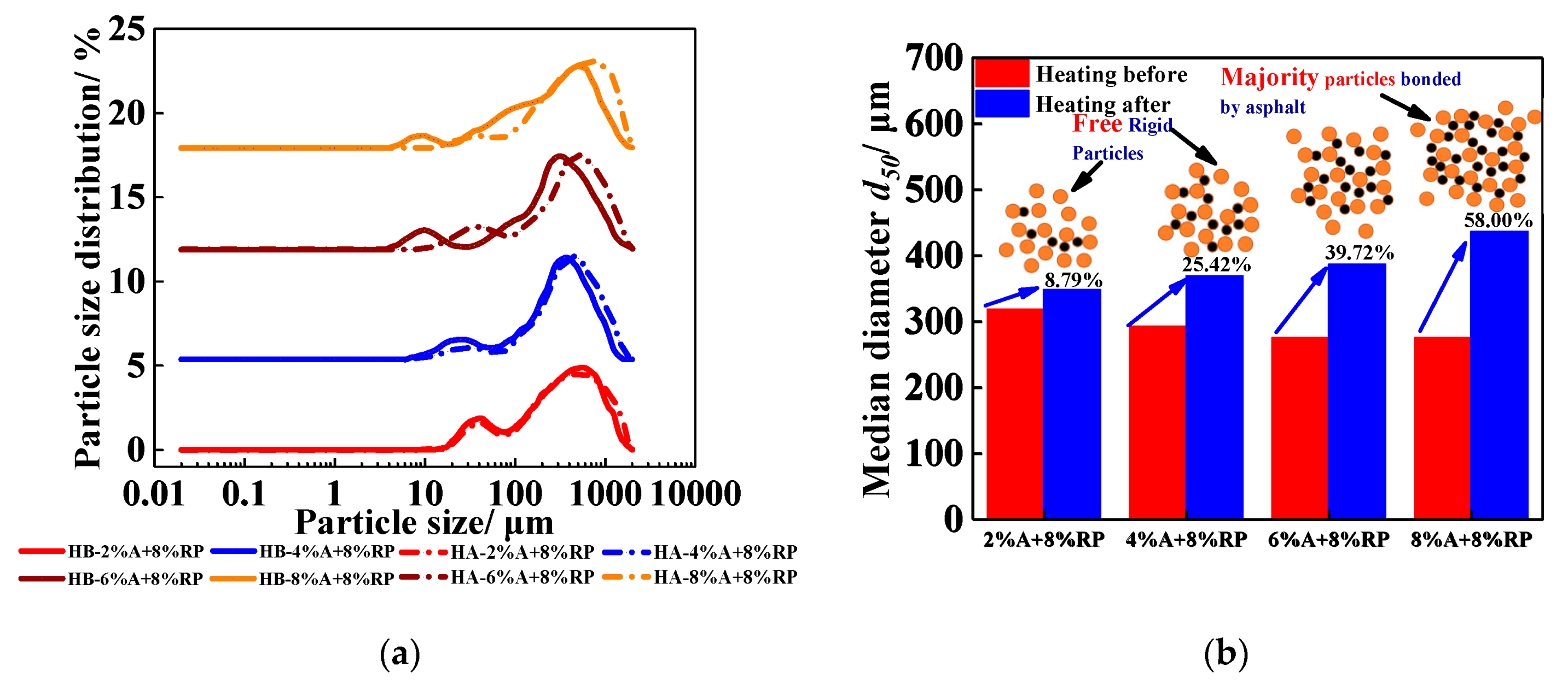
The PSD of asphalt and rigid particles in the dispersion medium (0.4 wt% xanthan gum solution) and the change in median particle size (d50) before and after subjection to high temperature are shown in Figure 8. The d50 of the anti-channeling system under different conditions increased after the high temperature, but the growth rate of d50 varied with different factors. Under different asphalt content conditions, d50 and the growth rate of the bonded system increased significantly with the asphalt content in the system (Figure 8a,b). The PSD curves of all the groups, except for the 2 wt% asphalt group, shifted to the right with different degrees of deviation after the high temperature. When the asphalt content was 2 wt%, the entire PSD curve did not deviate and the distribution value corresponding to the tailing peak of 10–79.621 μm decreased slightly. However, the distribution value of 792.214–2000.00 μm increased slightly, and d50 increased from 319.86 μm to 348 μm, with an increase of only 8.79%. When the asphalt content increased to 4 wt%, under the condition of fixed rigid particle size and content, the asphalt content around a single rigid particle increased, and the amount of asphalt bonding to particles increased. All PSD curves are slightly shifted to the right. The corresponding distribution values in the range of 7.096–63.246 μm were significantly reduced, the particle size of the main peak in the tail peak changed from 25.179 μm to 31.698 μm, the wide peak of the PSD curve increased from 355.656 μm to 447.744 μm, and the corresponding distribution values in the range of 7.096–355.656 μm are reduced. This result indicates that the asphalt in the system bonded with the rigid particles with a small size and grew into particles with a large size under the high-temperature environment. Then, the number of large particles increased (the overall curve moved to the right, and the corresponding distribution value increased in a certain range), and the number of small particles decreased (the distribution value of the trailed peak dropped). d50 increased from 293.85 μm to 368.56 μm, with a growth rate of 25.42%. When the asphalt content increased to 8 wt%, the curve shifted further to the right. The tailing peak moved from 4.477–20 μm to 14.159–63.249 μm, and the particle size of the main peak increased from 502.377 μm to 709.627 μm. The distribution value in the range of 4.477–158.866 μm decreased, and the value in the range of 158.866–2000 μm increased. With the increase in asphalt content, the asphalt bonded with the rigid particles effectively, and the d50 of system increased from 276.26 μm to 436.49 μm with a growth rate of 58%.
At different contents of rigid particles, the growth rate of the particle size of the anti gas-channeling system after heating presented a monotonous upward trend (Figure 9a,b). Within the range of 2 wt% to 6 wt% of particle content, the growth rate of d50 increased rapidly from 25.60% to 53.99%. When the asphalt content increased to 8 wt%, the growth rate decreased (only increasing from 53.99% to 58.00%). When the rigid particle content was only 2 wt%, the PSD curve presented an overall right-shift phenomenon, the tailing peak shifted right from 6.325–63.246 μm to 11.247–56.368 μm, and the corresponding distribution value in the range of 6.325–126.191 μm decreased. Given that the content of rigid particles was significantly lower than that of asphalt, the asphalt could fully cement the rigid particles in the system. The content of particles in the small particle size range decreased, whereas that in the large particle size range increased. The distribution value in the range of 126.191–2000 μm increased significantly. The particle sizes of the main peak in the wide peak were all 447.744 μm. Only the corresponding distribution value increased from 4.21% to 4.65%, and the d50 of the system increased from 235.51 μm to 295.80 μm, with a growth rate of 25.58%. When the particle content was 6 wt%, given that the d50 of the screened rigid particles was higher than that of asphalt, the increase in particle content increased the particle size at the initial condition (before the high temperature). Although the increase in particle content reduced the amount of asphalt around a single particle, the suspended asphalt in the solution was still sufficient to surround the rigid particles effectively. The tailing peak in the range of 6.325–63.426 μm shifted to the right, the particle size of the main peak shifted from 22.44 μm to 35.566 μm, the peak value of distribution decreased from 1.43% to 0.90%, and the value of PSD in the range of 6.325–282.508 μm also decreased to some extent. With the increase in particle size, the number of large particles increased, thereby increasing the distribution value within 282.508–2000 μm. The particle size of the main peak shifted from 502.377 μm to 632.546 μm, and the corresponding distribution value increased from 4.82% to 5.70%. Further bonding of asphalt in the solution to the rigid particles caused a significant change in PSD after heating, that is, d50 increased from 283.47 μm to 436.54 μm, with an increase of 53.99%.
When the particle content increased within a certain range (2 wt% to 6 wt%), as the content of rigid particles increases in the system, enough asphalt surrounded the rigid particles to bond with molten asphalt to form large particles. However, theoretically, the number of rigid particles that can be bonded by asphalt was determined under the condition of fixed asphalt content and rigid particle size. When the particle content exceeded this certain range, since the amount of asphalt surrounding a single rigid particle decreased, and some rigid particles were not surrounded by sufficient asphalt, leading to a poor bonding effect and a decrease in the growth rate of d50. Although the asphalt (8 wt%) dispersed in the xanthan gum solution can completely bond 6 wt% of the rigid particles, the bonding capacity of the asphalt is approaching the limit, in other words, when the content of the rigid particles continues to rise, the asphalt dispersed in the xanthan gum solution is not enough to completely bond the rigid particles. The PSD curve indicates that when the particle content increased to 8 wt%, although the entire curve shifted to the right, the deviation was not obvious compared with that in the 6 wt% particle system. In the wide peak of the PSD curve, the particle size of the main peak shifted from 502.377 μm to 709.627 μm, and the corresponding distribution value only increased from 4.82% to 5.15%. This change indicates that when the particle content increases to 8 wt%, the asphalt in the system can only bond a certain amount (6–8 wt%) of rigid particles, but the remaining particles cannot be bonded. Therefore, the d50 of the 8 wt% particle system only increased from 276.26 μm to 415.16 μm, with a growth rate of 58.00%, which is remarkably slower than that of the 2 wt% to 6 wt% particle systems.
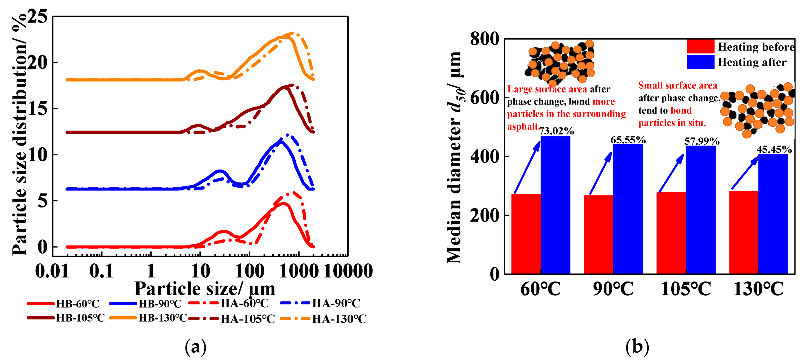
Under the condition of different softening points, the PSD of the anti gas-channeling system before and after heating is shown in Figure 10a,b. When the softening point of the asphalt was 130 °C, the tailing peak in the range of 4.477–31.698 μm shifted to the right to 7.096–50.238 μm, and the corresponding peak value decreased from 0.97% to 0.80% after heating. The particle size of the main peak increased from 502.377 μm to 632.456 μm, and the corresponding distribution value in the range of 502.377–2000 μm increased. Meanwhile, the d50 of the anti gas-channeling system increased from 280.60 μm to 384.67 μm, with an increase of only 45.45%. When the softening point of asphalt dropped to 60 °C, its PSD changed considerably compared with that of the asphalt with the softening point at 130 °C. The range of the tailing peak shifted from 5.637–63.246 μm to 8.934–112.468 μm, the particle size of the main peak in this region rose from 31.698 μm to 44.744 μm, and the corresponding distribution value dropped from 1.68% to 0.77%. The distribution value of the anti gas-channeling system in the range of 5.637–251.785 μm decreased evidently. The particle size of the main peak of the wide peak in the PSD curve increased from 502.377 μm to 796.214 μm, and the corresponding distribution value increased from 4.71% to 5.74%. The degree of deviation to the right was the largest in the four softening points of asphalt.
It can be seen from the change of d50 before and after heating that the growth rate of particle size decreases with the increase of the softening point. Given that asphalt is a mixture with complex components, it has only a melting range with no fixed melting point. Take two kinds of softening point asphalt as an example: 60 °C softening point asphalt and 130 °C softening point asphalt. When they both are at 130 °C, the former can melt completely, while for the latter, this temperature is only the point at which the asphalt starts to become soft. In other words, for asphalt particles of the same size, at the same temperature, the components inside the low softening-point asphalt have been completed melted, completing the phase transition process from solid phase to liquid phase. However, for the high softening-point asphalt, there is still some material inside that has not melted and the phase transition is incomplete. After the phase transition, the asphalt with the low softening point has a larger surface area when it changes to the liquid phase from the solid phase, so it can bond more rigid particles. However, the asphalt with the high softening point cannot be completely molten, its bonding capability cannot be fully utilized (this part of the process can be seen in the schematic diagram), the particle size growth rate of the system after bonding is not as good as that of the system with low softening point. The growth rate of particle size in 130 °C group was significantly different from that in the 60 °C group. d50 increased from 280.60 μm to 408.13 μm, only with a growth rate of 45.45%. While for the 130 °C group, the d50 increased from 270.6 μm to 468.14 μm, with a growth rate of 73.02%.

3.2. Suspension Performance of Rigid Particles

3.2.1. Selection of Thickeners

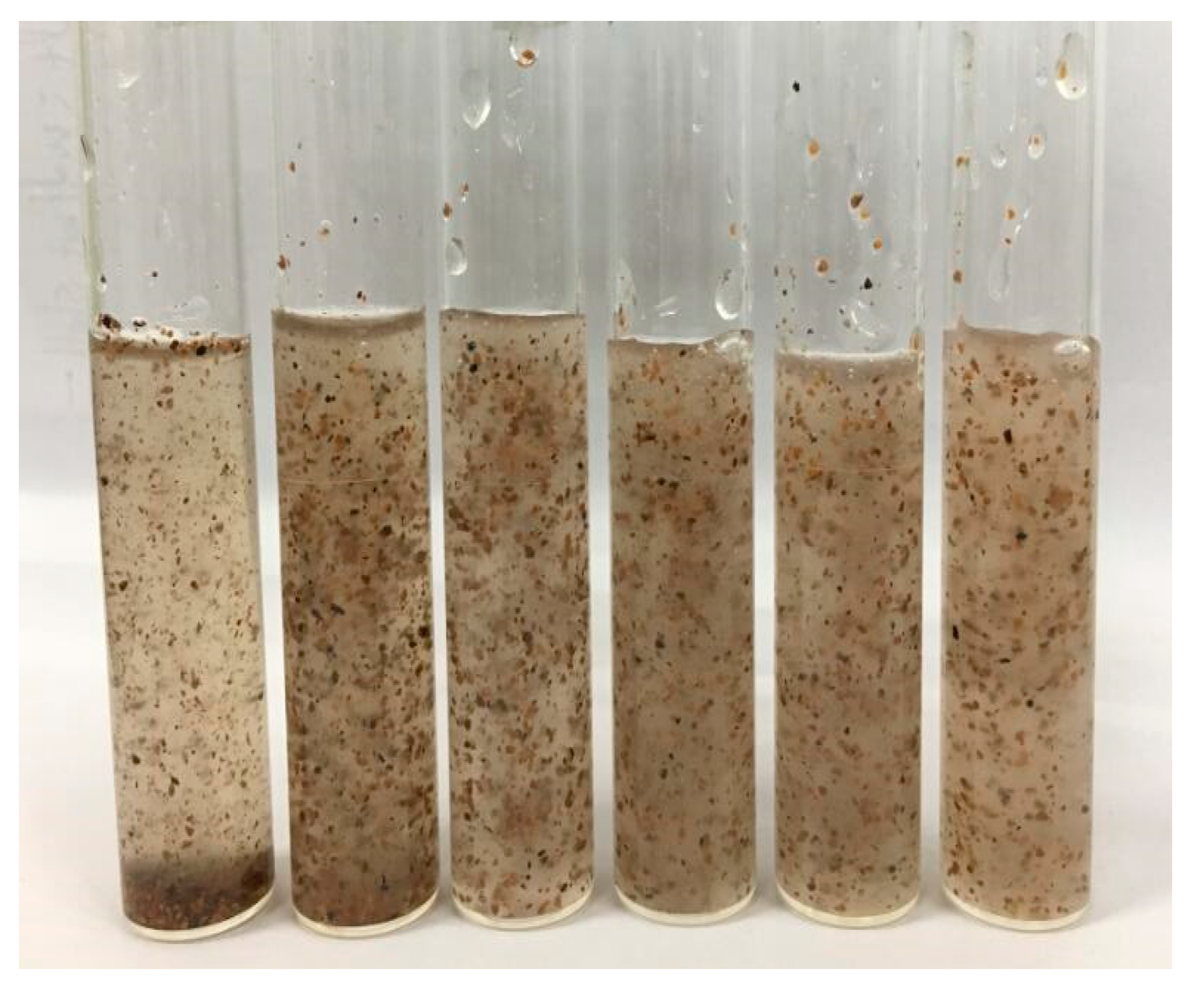
(1) Water-solubility of thickeners: the water-solubility of thickeners in high-salinity brine is shown in Figure 11. Among the three thickeners, HPAM and xanthan gum all formed a homogeneous solution with water, while AP-P4 forms a small amount of white flocculent precipitate (marked by the red box in Figure 11) in high-salinity brine. This is because AP-P4 is introduced by adding a side chain of the non-polar group on HPAM, which lead to the existence of a hydrophobic association force caused by hydrophobic aggregation of hydrophobic side groups between polymer molecules besides the hydrogen bond and van der Waal’s forces. The presence of these forces enhances the interaction between the polymer molecules to escape the polar environment of water and strengthens the cohesion between the AP-P4 molecules. This cohesion is much stronger than the hydrogen bond and van der Waal’s forces, therefore, the diffusion of polymer molecules from bulk to solvent (water) is significantly inhibited during the dissolution process. The increase of cohesion means poor water-solubility at the macro-level, and with the increase of salinity, the polarity of water is enhanced, the cohesion between hydrophobic groups becomes greater, and the solubility turns worse, thus AP-P4 can only swell but not dissolve in high-salinity brine. Therefore, only HPAM and xanthan gum were studied in the follow-up investigation of high-temperature steady-state rheological property and long-term viscosity retention performance.
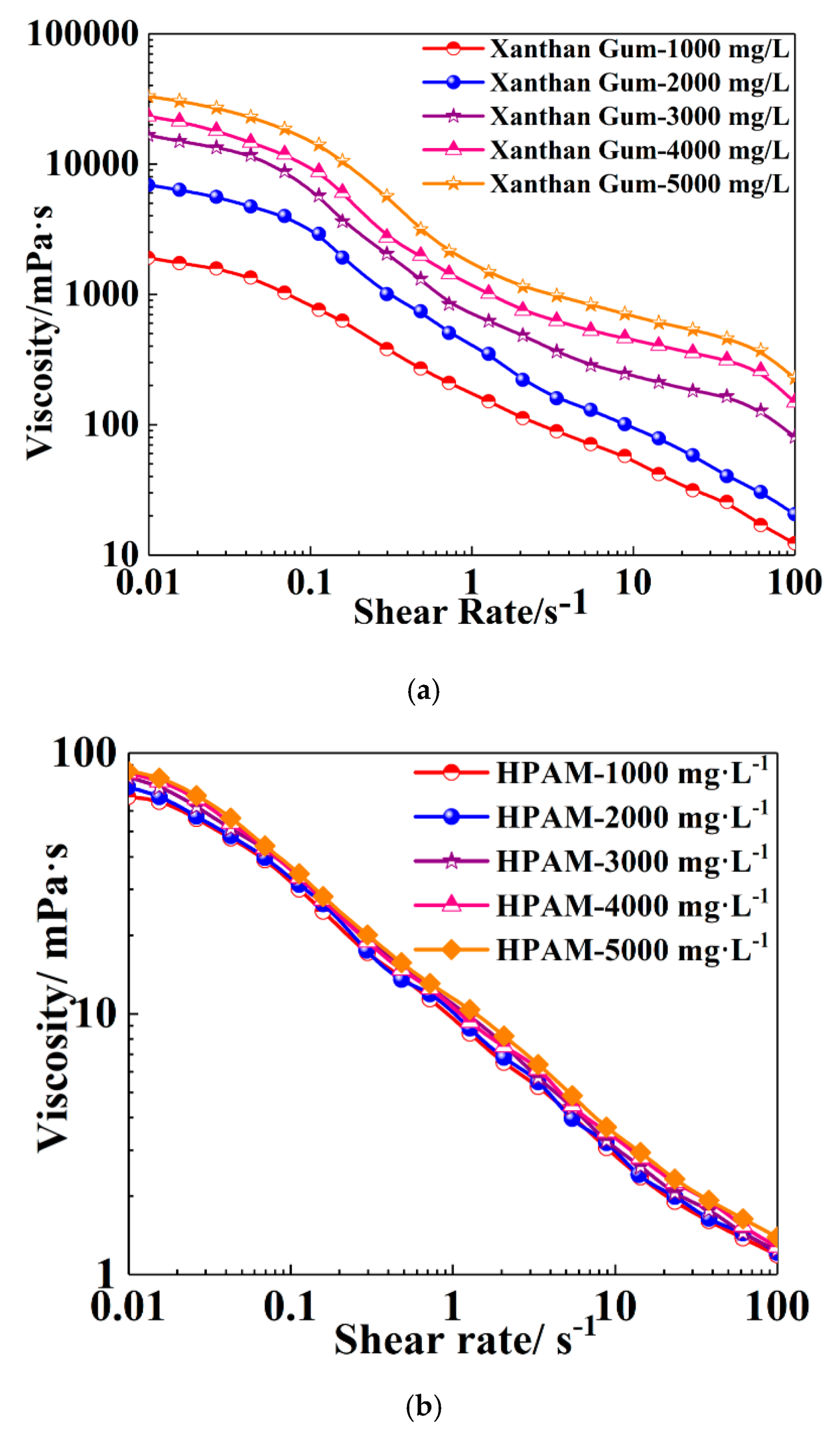
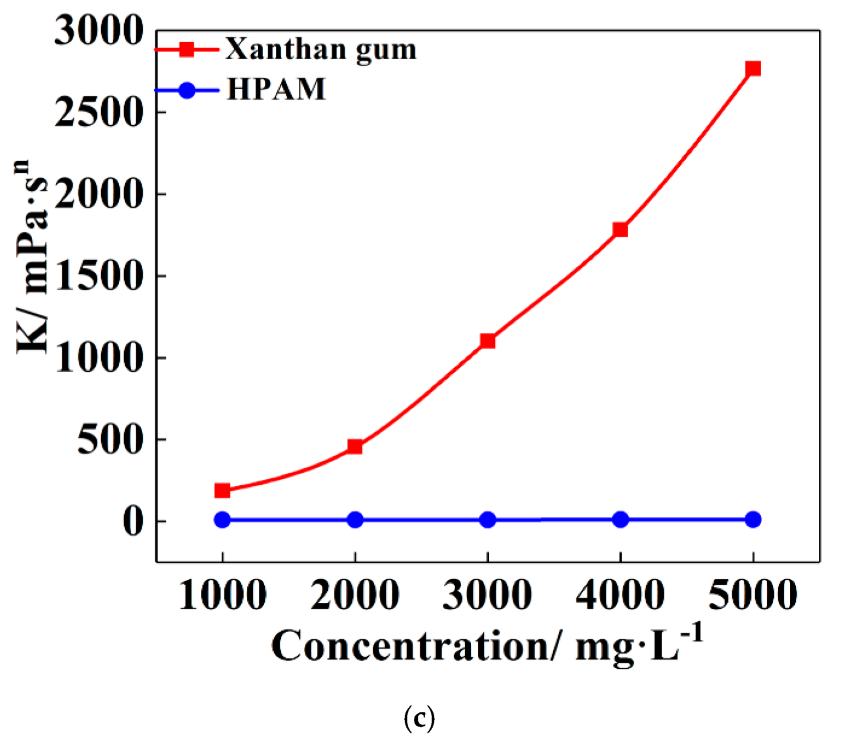
(2) Steady-state rheological property of thickeners at high-temperature: the steady-state rheological curves of HPAM and xanthan gum are shown in Figure 12a,b (the power-law function was used to fitting the steady-state rheological curves, and its correlation coefficient R2 were all higher than 0.98), and the change of consistency factor (K) with concentration is shown in Figure 12c. For the xanthan gum solution, the Newtonian region appeared in the γ range of 0.01–0.043 s−1 and 2.069–14.38 s−1 when the concentration is 3000-5000 mg·L−1, and is only distributed in low γ range (0.01–0.026 s−1) at concentrations of 1000 and 2000 mg·L−1. In the first Newtonian region, the external forces unwrap the tangles of polymer molecular chains and stretch them further, hence, the polymer chains exposed more groups and increased the degree of interaction among one another, resulting in maintaining the solution viscosity. For HPAM, due to electrostatic attraction between carboxaylic acid groups on its molecular chain and the existence of a large amount of metal ions such as Na+, Ca2+ and Mg2+, has a shielding effect, which causes the molecular chain change from a stretch state in pure water to a curl state in high-salinity brine, and this shielding effect is enhanced with the increase of temperature. It can be seen that when the concentration increases from 1000 mg·L−1 to 5000 mg·L−1, the steady-state rheological curves barely changed, and the increase of K only increased from 9.46 to 11.32. At the same time, the K of xanthan gum increased from 186.94 to 2765.8, and its thickening ability was remarkably improved compared with that of HPAM. Therefore, in the follow-up studies on long-term aging performance, only the long-term viscosity-retention performance of xanthan gum was studied.
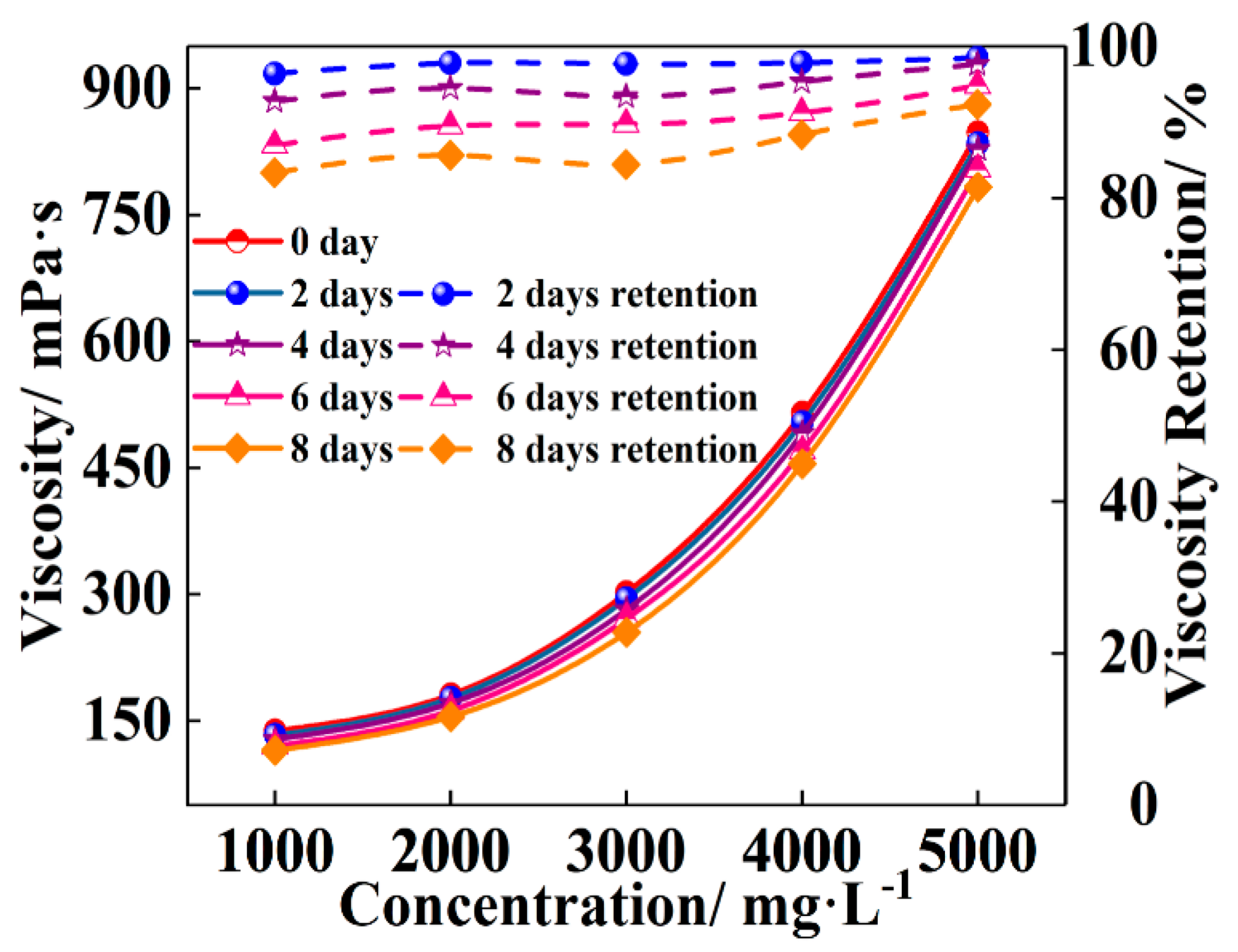
(3) Long-term viscosity-retention performance of thickener: the apparent viscosity and retention of xanthan gum at different aging times are shown in Figure 13. It can be seen that along with the aging time, the apparent viscosity of xanthan gum at different concentrations decreased, and the viscosity retention degree dropped with the extension of time, but the decrease degree was not big. After 8 days of high-temperature aging, the apparent viscosity retention of xanthan gum was as high as 83.33% (1000 mg·L−1) to 92.33% (5000 mg·L−1). Xanthan gum can still maintain high viscosity in the long-term high-temperature and high-salinity environment, which indicates an excellent performance of xanthan gum with carrying asphalt and rigid particles to the deep stratum to finish blocking tasks.

3.2.2. Suspension Properties of Xanthan Gum

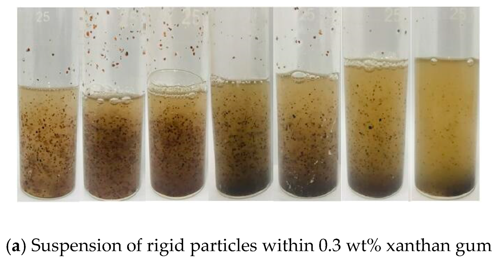
Figure 14 shows that the rigid particles were distributed in the solution unevenly, and most were deposited at the bottom of the tube when the xanthan gum concentration was lower than 0.3 wt%. The xanthan gum solution could suspend the rigid particles steadily and disperse them in the solution uniformly when the concentration increased to 0.3 wt%. However, due to the actual stirring process, especially in field construction, a small amount of air is inevitably mixed, and xanthan gum is prone to thermal oxygen degradation in high-temperature environments [54]. Then, the suspension capability to rigid particles is reduced or even lost, and the deep blocking task cannot be completed. Therefore, the xanthan gum concentration was further optimized through the high-temperature suspension performance. Given that the xanthan gum solution was only for carrying asphalt and rigid particles to the target zone, it only needed the minimum concentration to satisfy the requirements of suspension time. In this work, the high-temperature suspension performance of the 0.3–0.5 wt% xanthan gum solution was studied.
The suspension capability of xanthan gum at a high temperature is shown in Figure 15. For the 0.3 wt% xanthan gum, the suspension properties of the rigid particles in the solution were not affected by the high-temperature environment for 12 h. However, deposition occurred at the bottom of the tube when the aging time was 16 h. After 24 h, the xanthan gum solution basically lost its suspension capability for rigid particles, and all of the rigid particles carried by the solution were deposited at the bottom of the tube. For the 0.4 wt% xanthan gum, the performance of the suspended rigid particles was barely affected by the high temperature in the first 20 h. Although part of the rigid particles experienced deposition at 24 and 28 h, the solution could suspend most of them (a certain amount of rigid particles was suspended in the middle of the solution). When the xanthan gum concentration increased to 0.5 wt%, obvious deposition rigid particles began to occur at the bottom of the tube at 130 °C during the first 24 h, but the solution could still suspend most of the rigid particles. At 28 h, only a small amount of rigid particles could be suspended in the middle of the xanthan gum solution, and the deposition at the bottom of the tube was similar to that at 0.4 wt%.
In summary, the xanthan gum concentration of 0.5 wt% did not significantly improve the suspension performance of the rigid particles at high temperature compared with the 0.4 wt% concentration, and the xanthan gum solution only functioned as a suspension agent for carrying the rigid particles to the target layer. Increasing the xanthan gum concentration could cause injectivity problems. Additionally, in consideration of economic cost, the xanthan gum concentration was determined to be 0.4 wt%.

3.3. Study of the Anti Gas-Channeling Capability of the Asphalt Bonding System and Its Influencing Factors

3.3.1. Determination of the Maximum Injected Concentration of the Anti Gas-Channeling System

The optimized result of the maximum injected concentration of the anti gas-channeling system through the golden section algorithm is shown in Figure 16. The injectivity of the corresponding concentration groups was examined according to the experimental order of ① to ⑧. The value marked in red represents the experimental group with poor injectivity, that is, the asphalt and rigid particles blocked the entrance of the core during the injection process. Conversely, the values marked in black represent the experimental group without blockage of the injection port during the injection process. The pressure was relatively stable and did not increase in the experiment. According to the experimental results, for the core with a network fracture (2 mm width), the maximum concentration of the injected anti gas-channeling system was 8 wt% (C asphalt = C rigid particles = 8 wt%).

3.3.2. Dispersion of the Blocking Channeling System

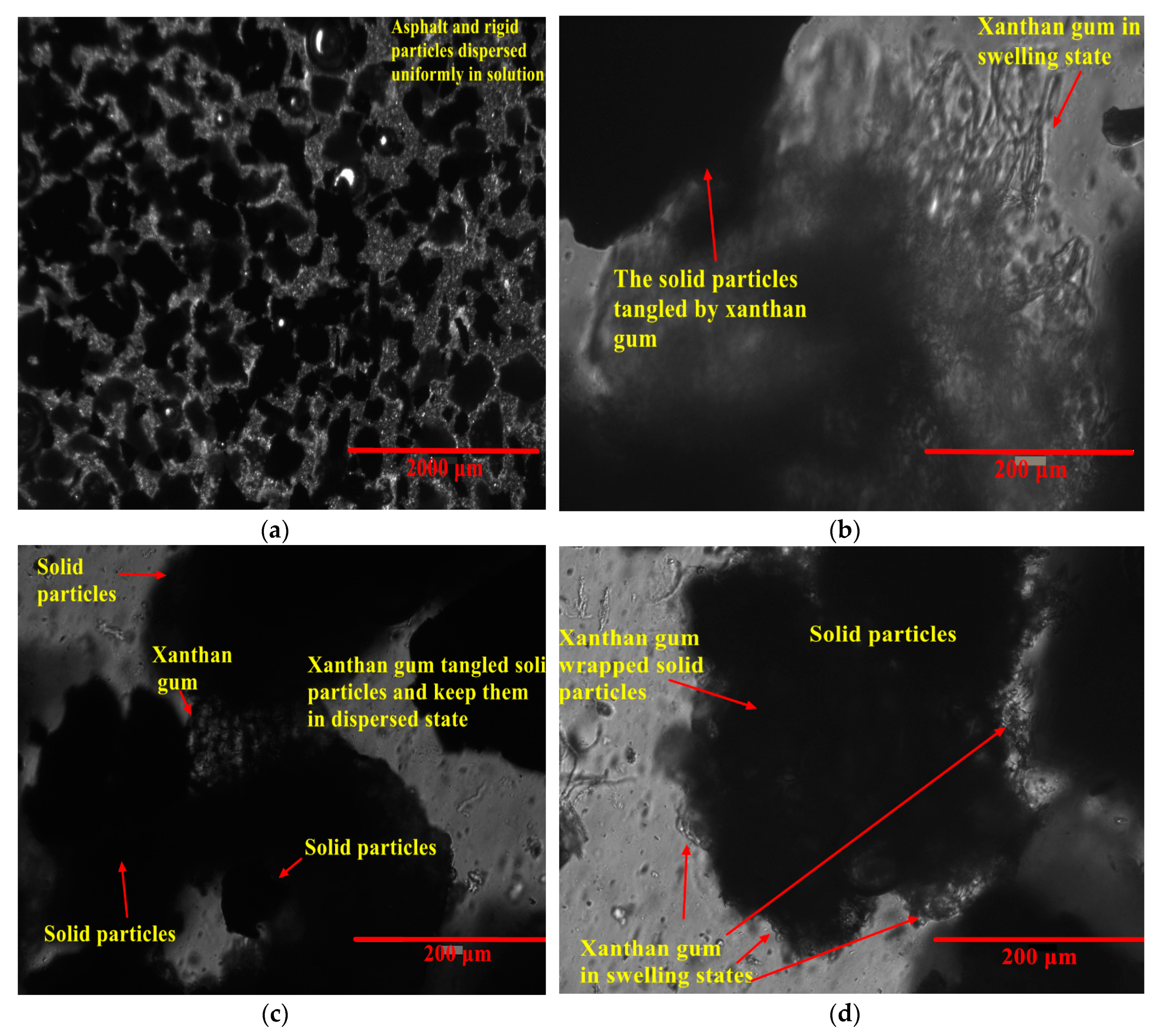
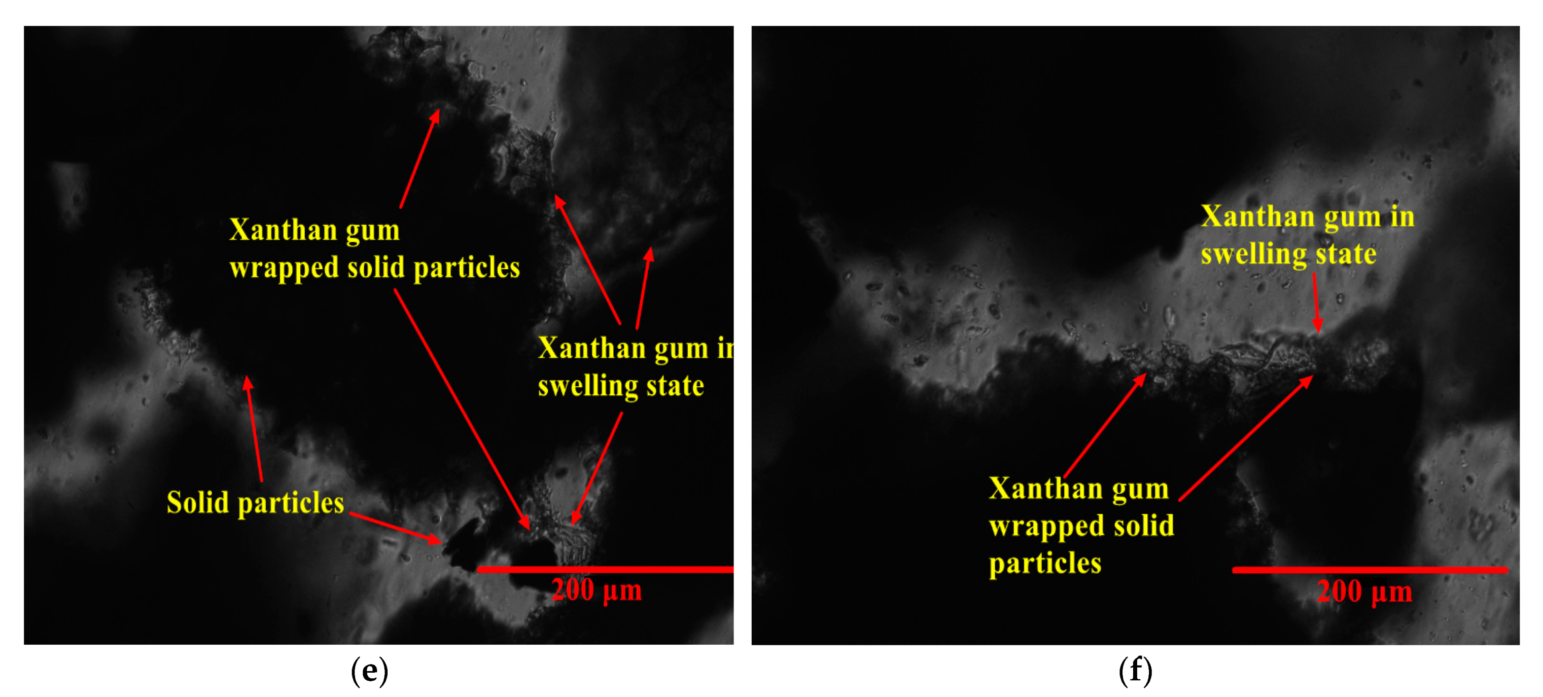
The blocking system was observed using the EVOS no-eyepiece inverted fluorescence microscope, and the results are shown in Figure 17. Given the roughly similar size of the two kinds of opaque solid particles, with both appearing as black solid blocks, the results obtained by optical microscopy could not discriminate between the asphalt and rigid particles. However, Figure 17a indicates that the rigid and asphalt particles were dispersed in the 0.4 wt% xanthan gum solution evenly. Meanwhile, the concentration of rigid particles and asphalt reached 8 wt%, and the solid particles in the solution were densely distributed. For 2 mm fractures, an injection port blockage will occur if the solid particle concentration continues to increase.
Although microimaging cannot differentiate solid particles efficiently, it can clearly distinguish between xanthan gum in the swelling state (transparent) and the solid particles (Figure 17b). Xanthan gum macromolecules can be coated on the surface of solid particles and bond with one another around them after swelling, thus forming a certain gap to ensure that the solid particles do not aggregate with each other so as to maintain the dispersion state of the system and facilitate the injection of the system. In addition, the wrapping of xanthan gum in swelling state to the rigid particles prevents asphalt from prematurely bonding with the rigid particles at high temperatures which leads to the anti gas-channeling system being unable to block the fractures in the deep formation, and even causing blocking near the wellbore.

3.3.3. Orthogonal Experiment Results and Analysis of Anti Gas-Channeling Performance

According to the orthogonal experiment scheme designed in Section 2.6.3, the results of the core-flooding experiments are shown in Table 4 in detail (the data in Table 4 are the mean values of the three measurements, see supplementary material Tables S1 and S2 for detailed single measurement data and standard error), and the measurement results after an intuitive analysis of the experimental results are shown in Table 5.
The data in Table 4 show that W0.25 MPa is always higher than W1 MPa. According to the theory of Li et al. [55], the boundary layer between the fluid (including gas) and the pipe wall has a certain thickness. However, the interaction force between gas molecules is much smaller than that between liquid molecules. Thus, the mobility of the boundary layer that is formed when the gas flows in the pore channels is stronger than that of the liquid molecules. According to Moody’s chart (see supplementary materials, Figure S1), the friction coefficient (λ) decreases linearly with the increase in Reynolds number (Re). As the fluid velocity increases, the boundary layer becomes thinner. The schematic representation is shown in Figure 18.
This thinning of the boundary layer occurs when the gas velocity increases because the airflow can drive more gas molecules in the boundary layer to move together, that is, the escape phenomenon generated by molecular thermal movement and collision leads to the thinning of the boundary layer and a large flow space. The intermolecular forces of gas are weakened, and the boundary layer becomes prone to thinning. Consequently, more gas molecules flow out together at a high pressure. The escape of gas molecules in the boundary layer can increase the gas velocity at the outlet to a certain extent, resulting in a significantly lower reduction rate of gas velocity at high pressure than at low pressure.
According to the results of range calculation, the influence sequence of the above three factors on the anti gas-channeling capability of the asphalt bonding system was C rigid particles > C asphalt > asphalt softening point. Moreover, the influence degree of rigid particle content on the anti gas-channeling effect was much higher than that of the asphalt content and its softening point. As bridging particles, the d50 of rigid particles was approximately 330 μm and served as a function of the blocking bridge formed in the fractures. If no rigid particles fill the channel space and serve as a bridge in the channeling fracture, then the asphalt will have no bonding site and cannot realize blocking. Thus, the content of rigid particles is the factor that exerts the most influence on the anti gas-channeling effect. Furthermore, Section 2.1 indicates that all kinds of asphalt can bond with rigid particles very well, with little difference in bonding performance. Thus, asphalt has the least impact on the blocking effect of the anti gas-channeling system. In addition, the asphalt content determines the compaction degree of the anti gas-channeling system’s bonding in the fracture and influences the flow of N2 through the blocking zone remarkably. However, without the pre-bridging of rigid particles in the fracture channel, asphalt cannot impose its bonding effect. Therefore, the influence degree of C asphalt is less than that of C rigid particles, but different contents of asphalt can bond with different contents of rigid particles. Therefore, the sensitivity of anti gas-channeling performance to the change in asphalt content is still higher than its softening point.
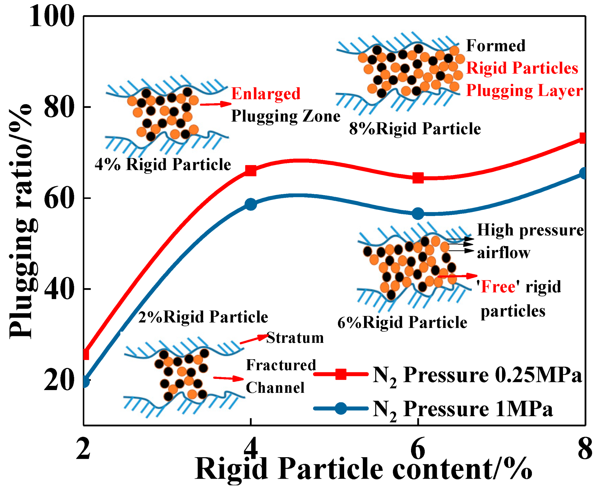
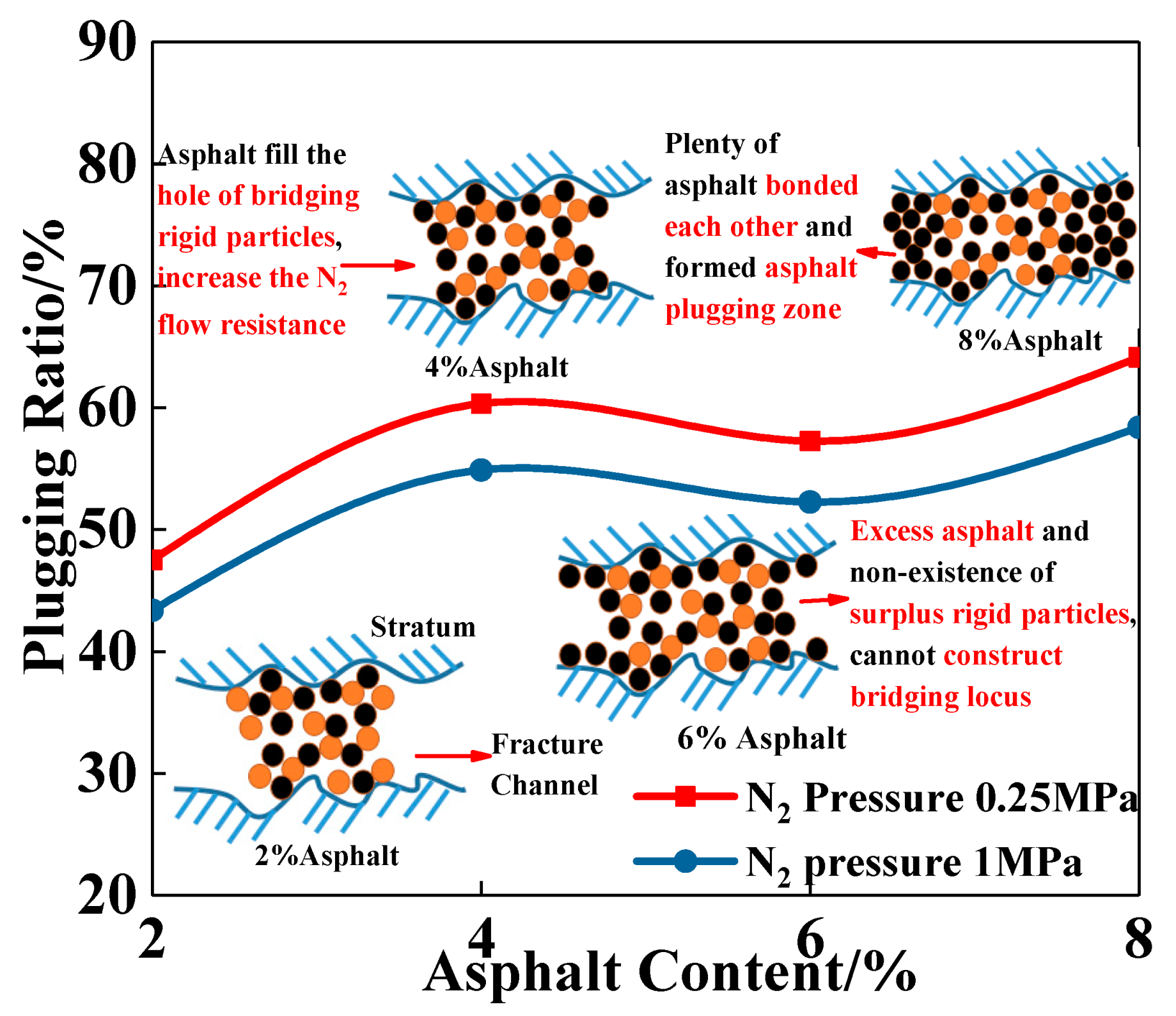
The level trend of C rigid particles is shown in Figure 19. With the increasing content of rigid particles, the plugging ratio exhibited an increasing trend first then decreased slightly and finally increased. The analysis suggests that while the content of rigid particles increased from 2 wt% to 4 wt%, the space of the fracture occupied by the rigid particles increased significantly, and the blocking capability of the system for the gas channeling fractures was strengthened obviously. Nevertheless, when the content of asphalt in the system was constant, the content of rigid particles that can be bonded by asphalt was also fixed. With increasing content of rigid particles (4 wt% → 6 wt%), the rigid particles occupied more of the system volume, further dispersing the asphalt distribution in the anti gas-channeling system and significantly decreasing the amount of asphalt around the single rigid particles. The number of unbound rigid particles increased and formed “free” solid particles. The blocking zone filled by “free” rigid particles could be easily washed away or even carried by the high-pressure N2 flow, thereby reducing the plugging ratio. However, as the rigid particle content continued to increase (6 wt% → 8 wt%), the rigid particles formed a “blocking layer” with a certain thickness and high mechanical blocking strength in the channeling fracture, which enhanced the blocking effect again.
The level trend of C asphalt is shown in Figure 20. With the content of asphalt rising from 2 wt% to 4 wt%, the amount of asphalt that bonded the rigid particles in the system increased to a certain extent, the pores formed by the accumulation of rigid particles were further filled by asphalt, the resistance of N2 flow through the blocking zone was enhanced, and the plugging ratio increased. Meanwhile, the capability of bridging and the occupied area of rigid particles in the channeling fracture were determined when the content of rigid particles in the system was constant. With the further increase in asphalt content (4 wt% → 6 wt%), most of the rigid particles in the system had already bonded with asphalt, and the small rigid particles could not construct a sufficient bridging locus. The excess asphalt transformed into a high-viscous liquid from a solid form, but the liquid form could not bridge or fill the fracture channel effectively, thereby decreasing the plugging ratio slightly with the increase in asphalt content. When the asphalt content increased from 6 wt% to 8 wt%, the excess asphalt increased continually. At this concentration level, the asphalt could also serve as bridging particles. The asphalt particles bonded with each other through their high viscosity to improve the degree of compaction and then increased the flow resistance of N2 through the fracture. Consequently, the plugging ratio increased in this asphalt content range.
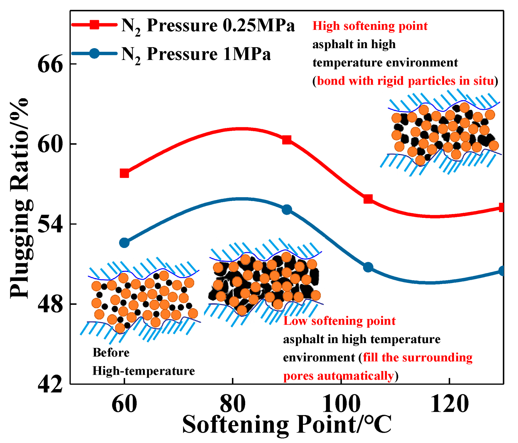
The level trend of the asphalt softening point is shown in Figure 21. With the increase in the softening point, the plugging ratio exhibited an increasing trend first and a decreasing trend later. The analysis suggests that when the softening point increased in a certain range (60 °C → 90 °C), the increase in viscosity helped strengthen the bonding performance between the asphalt and rigid particles, making the blocking layer difficult to shatter or wash away by high-pressure N2 flow and then improving the blocking capability. Furthermore, the softening point 90 °C of asphalt has good liquidity. After the asphalt transformed into a highly viscous liquid from the solid phase in the high-temperature environment, because the liquid phase volume is higher than solid phase, the asphalt could automatically fill the surroundings pores formed by solid bridging particles (rigid particles) through its ‘amoeba’ characteristic. Hence, the N2 flow passage was further reduced, and the flow resistance was increased. With the continuous increase in the asphalt softening point (90 °C → 130 °C), its apparent viscosity increased obviously, and the fluidity changes were poor in this environment. Given that asphalt is a compound with a complex composition, at high temperatures, many of its parts remain unconverted into the liquid phase completely and show a minimal change in volume in the phase transition process. Asphalt with a high softening point tends to soften in situ rather than migrate and fill the pores formed by the accumulation of rigid particles, leading to a decrease in anti gas-channeling performance. The variation trend of this experimental result is partially consistent with the change tendency of the growth rate of particle size before and after heating (Section 3.1.2, Figure 10). In other words, within a certain softening point range (90 °C–130 °C), with the increase of asphalt softening point, the growth rate of d50 and its blocking ratio of anti gas-channeling system both gradually decrease. At the same temperature, some of the substances with a high melting point in the high softening-point asphalt were not converted into liquid phase. At this time, although the viscosity of the asphalt was higher than that of the low softening-point asphalt, the poor fluidity also led to the fact that the asphalt could not completely exert its bonding ability and the number of rigid particles bonded is lower than that of the low softening-point asphalt. Asphalt with low softening point has good fluidity (e. g., the asphalt with softening point at 60 °C) and can bond more rigid particles. However, due to its low viscosity, it has poor bonding to rigid particles and poor anti gas-channeling performance. When choosing the softening point of asphalt in practical application, the fluidity of the asphalt, the bonding of rigid particles and the blocking of fractures should be considered comprehensively.
The optimal scheme (A4B4C2) obtained from the orthogonal experiment was subsequently verified. The experimental result is shown in Table 6. The plugging ratios of the optimal scheme reached 91.02% (P = 0.25 MPa) and 86.24% (P = 1 MPa), which are significantly enhanced compared with those of optimal group 15# (Table 4, W 0.25MPa = 84.90%, W 1MPa = 79.90%) in the orthogonal experiment.

3.3.4. The Long-Term Performance of Anti Gas-Channeling of Asphalt Bonding System

The long-term performance of anti gas-channeling of asphalt bonding system was shown in Figure 22 (see supplementary materials Tables S3 and S4 for detailed N2 flow rate measurement data). It can be seen that in the 30-day aging period, the system still has a high blocking capability for the fracture channel under the gas-flooding pressure of 0.25 MPa and 1 MPa, and the blocking rate is basically maintained at about 90% (0.25 MPa) and 86% (1 MPa). The long-term high-temperature environment had almost no effect to the blocking strength of the system. Given that asphalt and rigid particles are inert to the harsh conditions, high-temperature will not affect the mechanical strength, chemical composition and other physical and chemical properties of the two substances. In Section 3.1.1, the viscosity of asphalt at each softening point is basically unchanged at 130 °C, which enables the ability of asphalt to maintaining the bonding to the rigid particles and then guarantee the blocking strength of the system to the fracture channel.

3.4. Distribution of the Anti Gas-Channeling System in Network Fractures

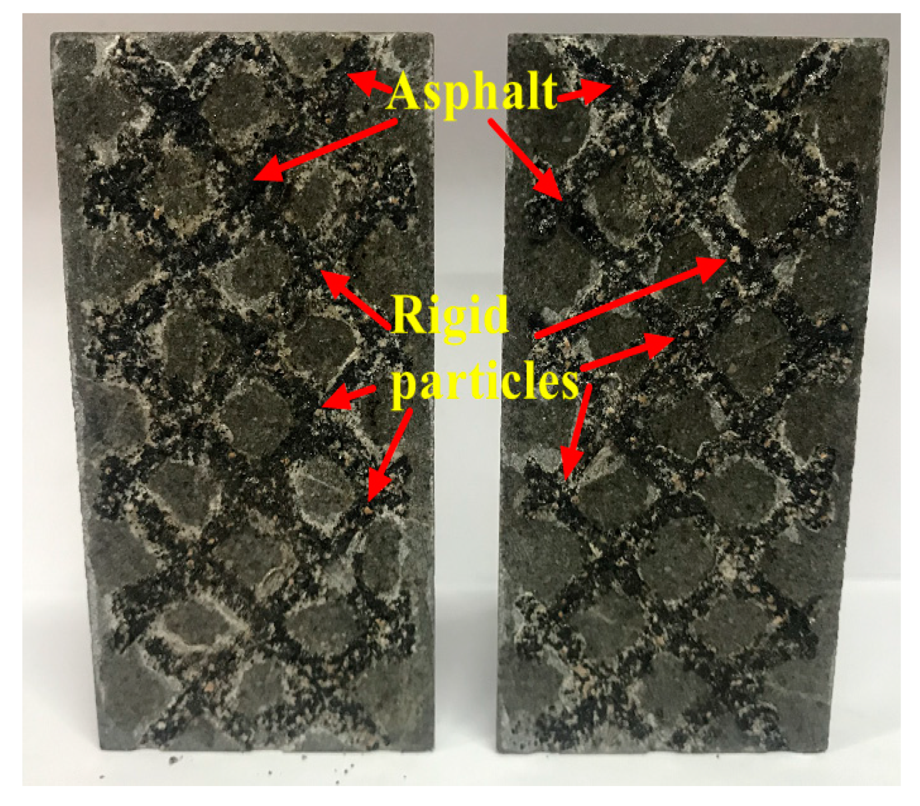
Xanthan gum carries the main blocking agent and establishes the blocking layer in the core fracture by the action of gravity sedimentation. In actual reservoirs, the gas-channeling paths are composed of multiple fractures, and whether the main blocking agent can settle evenly in the fracture is the key factor that affects the blocking effect of anti gas-channeling system. Therefore, by contrast with the single fracture channel cores used in other reports [29,30,31,32,56], this research adopts the network fracture cores to investigate the blocking performance of the anti gas-channeling system. After testing the anti gas-channeling performance of the optimal scheme, the simulated core was cut open to observe the distribution of the anti gas-channeling system in the network fracture. The internal distribution is shown in Figure 23.
The black solid inside the fractures is asphalt, and the rigid particles are colored brown. The figure shows that the anti gas-channeling system can settle evenly at the corner of each fracture and can be distributed uniformly throughout the internal network fractures, which is conducive to the establishment of uniform resistance in the fractures of the system. Furthermore, the system could produce a certain height of accumulation in the fractures and occupy the channel completely. In this high-temperature environment, the asphalt in the system could bond with the rigid particles through its high-viscosity characteristics and then reduce the radius of N2 flow passing through the channels, thereby increasing the resistance of N2 flow and further improving the blocking effect of the system.

3.5. Observation of the Micromorphology of the Bonding System inside the Fractures

After the fractured core was cut open, the blocking layer inside the fracture was taken out, and ESEM was used to observe the micromorphology of the bonding system, as shown in Figure 24. The rigid particles presented a loose and porous structure. The smooth surface became flaky asphalt after heating. The following four images show that the asphalt bonded with and coated the rigid particles. Figure 24d indicates that the asphalt bonded and fixed many rigid particles, implying that the asphalt transformed into the highly viscous liquid phase in the high-temperature environment and filled the pores that were formed by the bridging rigid particles. The asphalt demonstrated its “amoeba” characteristic by filling the bridging pores automatically and making the rigid particles in the surroundings bond with each other. The flow resistance through the fractures increased and enhanced the anti gas-channeling effect of the system while ensuring that the blocking area formed by the rigid particles was not carried by the high-temperature N2 flow.

4. Conclusions

(1) The particle size range of asphalt and rigid particles was determined according to classical bridging theory and the actual width of the fracture. The maximum injection concentration of asphalt and rigid particles was 8 wt%.
(2) Xanthan gum has good water-solubility in high-salinity brine, its apparent viscosity is much higher than that of HPAM, and its long-term viscosity is good. The concentration of xanthan gum solution (0.4 wt%) was determined according to the properties of rigid particles suspended at 25 °C and 130 °C.
(3) Asphalt has good bonding performance to rigid particles in high-temperature conditions. By studying the influence of various factors on the growth of particle size after bonding in high-temperature, the maximum particle size after cementation can be achieved through reasonable adjustment of the softening point, the content of asphalt and rigid particles to enhance the capability of anti gas-channeling of the system.
(4) The optimal formulation of the system is 8 wt% asphalt (softening point 90 °C) + 8 wt% rigid particles. The blocking rate of the system for network fractures cores with a width of 2 mm reached 86.24% (1 MPa) and 91.02% (0.25 MPa) under the conditions of high-temperature (T = 130 °C) and high-salinity (TDS = 223.07 g·L−1). The sensitivity order of the three factors to the blocking rate is: C rigid particles > C asphalt > asphalt softening point.
(5) The anti gas-channeling system was evenly distributed in the network fractures, occupied the fracture completely, and had a certain height of accumulation. The long-term high-temperature conditions had almost no effect on the blocking strength of the system. The micromorphology of the system in the fractures showed that asphalt has a good bonding effect on rigid particles in high-temperature environments, preventing the high-pressure N2 flow from breaking down the blocking zone in the subsequent gas-flooding process and improving the anti gas-channeling effect of the system on fractures.

Supplementary Materials

The following are available online at https://www.mdpi.com/1996-1073/12/24/4766/s1, Figure S1: Moody’s chart, Table S1: Measurement data of N2 flow rate (Orthogonal experiment, N2 pressure 0.25 MPa), Table S2: Measurement data of N2 flow rate (Orthogonal experiment, N2 pressure 1 MPa), Table S3: Measurement data of N2 flow rate (Long-term performance, N2 pressure 0.25 MPa), Table S4: Measurement data of N2 flow rate (Long-term performance, N2 pressure 1 MPa).

Author Contributions

Conceptualization, N.L.; methodology, Y.W.; investigation, Y.W., X.W., W.H. and X.L.; resources: N.L.; data curation, Y.W. and C.J.; writing-original draft preparation, Y.W. and D.H.; writing-review and editing, Y.W. and W.H.; supervision, N.L.

Acknowledgments

We gratefully acknowledge financial support from the National Natural Science Foundation of China (51674208), the Science and Technology Project of Nanchong Municipal (NC17SY4017), the Open Fund (K2017-25) of the State Key Laboratory of Molecular Engineering of Polymers (Fudan University), the Open Fund (PLC20180103) of the State Key Laboratory of Oil and Gas Reservoir Geology and Exploitation (Chengdu University of Technology), the PetroChina Innovation Foundation (2018D-5007-0207), the Science and Technology Planning Project of Sichuan Province (2018JY0515), and the Undergraduate Extracurricular Open Experiment of Southwest Petroleum University (KSZ18440, KSZ18442).

Conflicts of Interest

The authors declare that they have no conflict of interest.

References

  1. Abedini, A.; Torabi, F. On the CO2 storage potential injection process for enhanced oil recovery. Fuel 2014, 124, 14–27. [Google Scholar] [CrossRef]
  2. Wei, B.; Gao, H.; Pu, W.; Zhao, F.; Li, Y.; Jin, F.; Sun, L.; Li, K. Interactions and phase behaviors between oleic phase and CO2 from swelling to miscibility in CO2-based enhanced oil recovery (EOR) progress: A comprehensive visualization study. J. Mol. Liq. 2017, 232, 277–284. [Google Scholar] [CrossRef]
  3. Bardon, C.; Corlay, P.; Longeron, D.; Miller, B. CO2 huff ‘n’ puff revives shallow light oil-depleted reservoirs. SPE Reserv. Eng. 1994, 9, 92–100. [Google Scholar] [CrossRef]
  4. Haskin, H.K.; Alston, R.B. An evaluation of CO2 huff ‘n’ puff tests in Texas. J. Pet. Technol. 1989, 41, 177–184. [Google Scholar] [CrossRef]
  5. Wei, Y.; Lashgari, H.R.; Wu, K.; Sepehrnoori, K. CO2 injection for enhanced oil recovery in Bakken tight oil reservoirs. Fuel 2015, 159, 354–363. [Google Scholar]
  6. Yang, F.; Sun, Y.; Shen, Y.; Zhang, L. Using diagenetic facies to analyze heterogeneous reservoir of Donghe sandstone of east slope of Lunnan, Tarim Basin. Pet. Explor. Dev. 2006, 33, 136–140. [Google Scholar]
  7. Zhong, G.; Wu, N. Development lithofacies analysis: A whole new approach to studying diagenetic heterogeneity. Pet. Explor. Dev. 1997, 24, 62–66. [Google Scholar]
  8. Hu, Z.; Ma, K.; Liu, Z.; Huang, K.; Zhang, J. An Research and application of the properties variation regularity of water injection reservoirs in S offshore oilfield. Sci. Technol. Eng. 2014, 14, 164–168. [Google Scholar]
  9. Li, X.; Sun, C.; Zhao, Y. Research on variation rule of reservoir microscopic and features in Lamadian oilfield. Pet. Geol. Oilfield Dev. Daqing 2007, 26, 79–82. [Google Scholar]
  10. Jin, F.; Tian, Y.; Pu, W.; Yuan, C.; Guo, Y.; Liu, Z. An experiment study of gas-channeling blocking by salt precipitation. Nat. Gas Ind. 2013, 33, 74–78. [Google Scholar]
  11. Lin, S.; Peng, W.; Pu, W.; Wang, B.; Wu, Y.; Tan, T. The oil recovery enhancement by nitrogen foam in high-temperature and high-salinity environments. J. Pet. Sci. Eng. 2016, 147, 485–494. [Google Scholar]
  12. Cao, X.; Liu, D.; Zhang, Z.; Wang, S.; Wang, Q.; Xia, D. Steam channeling control in the steam flooding of super heavy oil reservoirs, Shengli Oilfields. Pet. Explor. Dev. 2012, 39, 785–790. [Google Scholar] [CrossRef]
  13. Jones, S.A.; van der Bent, V.; Farajzadeh, R.; Rossen, W.R.; Bonnieu, V. Surfactant screening for foam EOR: Correlation between bulk and core-flood experiments. Colloids Surf. A Physicochem. Eng. Asp. 2016, 500, 166–176. [Google Scholar] [CrossRef]
  14. Jun, Y.; Wang, X.; Peng, X.; Du, Z.; Zeng, F. Experimental studies on CO2 foam performance in the tight cores. J. Pet. Sci. Eng. 2019, 175, 1136–1149. [Google Scholar]
  15. Sun, L.; Bai, B.; Wei, B.; Pu, W.; Wei, P.; Li, D.; Zhang, C. Recent advances of surfactant-stabilized N2/CO2 foams in enhanced oil recovery. Fuel 2019, 241, 83–93. [Google Scholar] [CrossRef]
  16. Hunter, B.L.; Buell, R.S.; Abate, T.A. Application of polymer gel system to control steam breakthrough and channeling. In Proceedings of the SPE Western Regional Meeting, Bakersfield, CA, USA, 30 March–1 April 1992. [Google Scholar]
  17. Eson, R.L.; Cooke, R.W. A successful high-temperature gel system to reduce steam channeling. In Proceedings of the SPE Annual Technical Conference and Exhibition, Washington, DC, USA, 4–7 October 1992. [Google Scholar]
  18. Wang, C.; Liu, H.; Wang, J.; Hong, C.; Dong, X.; Meng, Q.; Liu, Y. A novel high-temperature gel to control the steam channeling in heavy oil reservoir. In Proceedings of the SPE Heavy Oil Conference, Calgary, AB, Canada, 10–12 June 2014. [Google Scholar]
  19. Anzhu, A.X.; Mu, L.; Bo, B.; Shan, F.; Li, X. Development and application of a modified superheated steam flooding assisted by N2 foam and high-temperature resistant gel. In Proceedings of the Abu Dhabi International Petroleum Exhibition & Conference, Abu Dhabi, UAE, 13–16 November 2017. [Google Scholar]
  20. Hou, Y.; Yue, X. Research on a novel composite gel system for CO2 through. Pet. Sci. 2010, 7, 245–250. [Google Scholar] [CrossRef] [Green Version]
  21. Hughes, T.L.; Friedmann, F.; Johnson, D.; Hild, G.P.; Wilson, A.; Davies, S.N. Large-volume foam-gel treatments to improve conformance of the Rangely CO2 flood. SPE Reserv. Eval. Eng. 1999, 2, 14–24. [Google Scholar] [CrossRef]
  22. Romero-Zeron, L.B.; Kanzatzas, A. Flow visualization studies on the effect of foamed gel microstructure on gas-blockage effectiveness and its importance on foamed gel trapping in porous media. In Proceedings of the Canadian International Petroleum Conference, Calgary, AB, Canada, 11–13 June 2002. [Google Scholar]
  23. Kanzatzas, A.; Allsopp, K.; Marentette, D. Utilization of polymer gels polymer enhanced foams and foamed gels for improving reservoir conformance. In Proceedings of the Annual Technical Meeting, Calgary, AB, Canada, 8–11 June 1997. [Google Scholar]
  24. Romero, L.; Kanzatzas, A. The effect of wettability and pore geometry on foamed gel blockage performance in gas and water producing zones. In Proceedings of the SPE/DOE Symposium on Improved Oil Recovery, Tulsa, OK, USA, 17–21 April 2004. [Google Scholar]
  25. Han, X.; Zou, J.; Wang, Q.; Liu, Y.; Meng, X. A study of gel-plugging agents used in gas channels with multi-thermal fluids in offshore oilfields. J. Southwest Pet. Univ. (Sci. Technol. Ed.) 2017, 39, 167–172. [Google Scholar]
  26. Yu, H.; Li, L.; Zheng, J.; Ji, W.; Qin, X.; Fu, X.; Gao, W. New method of steam channeling plugging on horizontal wells of heavy oil stimulation. In Proceedings of the SPE Latin America and Caribbean Heavy and Extra Heavy Oil Conference, Lima, Peru, 19–20 October 2016. [Google Scholar]
  27. Zhou, Y.; Li, Z.; Zhang, L.; Jing, C.; Zhang, Z.; Li, X. Carbon dioxide flooding channeling blocking technology in fractured low permeability reservoirs. Oilfield Chem. 2017, 34, 64–68. [Google Scholar]
  28. Wang, Z.; Bai, B.; Liu, Y.; Wang, L. An investigation of CO2-responsive preformed particles gel for conformance control of CO2 flooding in reservoirs with fractures or fracture-like channels. SPE J. 2019, 24, 2398–2408. [Google Scholar] [CrossRef]
  29. Hu, L.; Zhao, J.; Wei, P.; Zhang, Y. Experimental study on enhanced foam anti-gas channeling in the Yumen H low permeability fractured reservoir. J. Southwest Pet. Univ. (Sci. Technol. Ed.) 2019, 41, 96–104. [Google Scholar]
  30. Shi, L.; Dang, H.; Kang, S.; Wang, W.; Wang, Q. Effects of injection pressure on gas channeling during CO2 flooding and a study on sealing of cracks. J. Southwest Pet. Univ. (Sci. Technol. Ed.) 2018, 40, 149–156. [Google Scholar]
  31. Yang, H.; Jiang, S.; Wang, H.; Li, P.; Nan, Y.; Du, X. Research of adaptability of gas channeling controlling methods in CO2 flooding of fractured ultra-low permeability reservoir. J. Xi’an Shiyou Univ. (Nat. Sci. Ed.) 2017, 32, 105–115. [Google Scholar]
  32. Liu, Z.; Li, Z. An experimental study on anti-channeling technology with foam in CO2 flooding. J. Southwest Pet. Univ. (Sci. Technol. Ed.) 2015, 37, 117–122. [Google Scholar]
  33. Wang, F. Numerical simulation research of asphalt profile development mode and mechanism after polymer flooding. Fault-Block Oil Gas Field 2015, 22, 364–368. [Google Scholar]
  34. Gao, B. Bitumen particles profile control technique in Lamadian oilfield. Pet. Geol. Oilfield Dev. Daqing 2006, 25, 96–98. [Google Scholar]
  35. Bai, Y. Parameters Optimization for Asphalt Particle Profile Control in Lamadian Oilfield. Master’s Thesis, Northeast Petroleum University, Daqing, China, 2017. [Google Scholar]
  36. Xiao, K.; Jiang, H.; Wang, Q.; Wang, H.; Zhao, D. Adaptability study on plugging thief zones with asphalt particle in polymer flooding offshore field. In Proceedings of the SPE Energy Resources Conference, Port of Spain, Trinidad and Tobago, 9–11 June 2014. [Google Scholar]
  37. Liu, G.; Jiang, H.; Li, J.; Wang, M.; Chen, F.; Ding, S.; Lu, X. Evaluation of the performance of polymer gels mixed with asphalt particle as a novel composite profile control system. J. Ind. Eng. Chem. 2015, 26, 309–314. [Google Scholar] [CrossRef]
  38. Li, Y.; Xiang, G.; Wang, Y.; Li, Y.; Li, J. Matching of asphalt particles and formation pores for conformance control treatment in Lamadian oilfield in Daqing. J. China Univ. Pet. (Ed. Nat. Sci.) 2015, 39, 92–96. [Google Scholar]
  39. Cao, G.; Bai, Y.; Li, X.; Zhou, Z.; Ren, C.; Li, Z.; Li, C. Size optimization of asphalt particles for profile for profile control in Lamadian oilfield P reservoir. In Proceedings of the 5th International Conference on Advanced Engineering Materials and Technology, Guangzhou, China, 22–23 August 2015. [Google Scholar]
  40. Abrams, A. Mud design to minimize rock impairment due to particle invasion. J. Pet. Technol. 1977, 29, 586–592. [Google Scholar] [CrossRef]
  41. Oort, E.V.; Velzen, J.F.G.; Leerlooijer, K. Impairment by suspended solids invasion: Testing and prediction. Spe Prod. Facil. 1993, 8, 178–184. [Google Scholar] [CrossRef]
  42. Zhang, J.; Yan, J. New theory and method for optimizing the particle size distribution of bridging agents in drilling fluids. Acta Pet. Sin. 2004, 25, 88–95. [Google Scholar]
  43. Guo, Y.; Hu, J.; Zhang, X.; Feng, R.; Li, H. Flow behavior through porous media and microdisplacemnet performance of hydrophobically modified partially hydrolyzed polyacrylamide. SPE J. 2016, 21, 688–705. [Google Scholar] [CrossRef]
  44. Gao, J.; Li, Y.; Li, J.; Li, J.; Yin, D.; Wang, H. Experimental study on optimal polymer injection timing in offshore oilfields. In Proceedings of the Offshore Technology Conference Asia, Kuala Lumpur, Malaysia, 25–28 March 2014. [Google Scholar]
  45. Han, M.; Xiang, W.; Zhang, J.; Wei, J.; Sun, F. Application of EOR technology by means of polymer flooding in Bohai oilfields. In Proceedings of the International Oil & Gas Conference and Exhibition, Beijing, China, 5–7 December 2006. [Google Scholar]
  46. Wang, D.; Han, P.; Shao, Z.; Hou, W.; Seright, R.S. Sweep-improvement options for the Daqing oil field. SPE J. 2008, 11, 18–26. [Google Scholar] [CrossRef]
  47. Ohen, H.A.; Blick, E.F. Golden section search method for determining parameters in Robertson-stiff non-Newtonian fluid model. J. Pet. Sci. Eng. 1990, 4, 309–316. [Google Scholar] [CrossRef]
  48. Kheldoun, A.; Bradai, R.; Boukenoui, R.; Mellit, A. A new golden section method-based maximum power point tracking algorithm for photovoltaic systems. Energy Convers. Manag. 2016, 111, 125–136. [Google Scholar] [CrossRef]
  49. Curvas, E.; Enriquez, L.; Zaldivar, D.; Perez-Cisneros, M. A selection method for evolutionary algorithms based on the golden section. Expert Syst. Appl. 2018, 106, 183–196. [Google Scholar]
  50. Li, Y.; Hu, C. Experiment Design and Data Processing; Chemical Industry Press: Beijing, China, 2008; pp. 114–115. [Google Scholar]
  51. Zhao, F.; Zhang, L.; Hou, J.; Cao, S. Profile improvement during CO2 flooding in ultra-low permeability reservoirs. Pet. Sci. 2014, 11, 279–284. [Google Scholar] [CrossRef] [Green Version]
  52. Jiang, S.; Wang, W.; Huang, C.; Yang, H.; Yu, H. Application of modified starch gel system to prevent CO2 breakthrough. Spec. Oil Gas Reserv. 2016, 23, 136–140. [Google Scholar]
  53. Zhang, H.; Cao, Y.; Liu, F.; Zhang, A.; Liu, T.; Yong, Q. Microstructure and formula optimization of CO2 flooding composite gel channeling sealing system. Oilfield Chem. 2017, 34, 64–68. [Google Scholar]
  54. Wei, B.; Romero-Zer, N.L.; Rodrigue, D. Improved viscoelasticity of xanthan gum through self-association with surfactant: β-cyclodextrin inclusion complexes for application in enhanced oil recovery. Polym. Eng. Sci. 2015, 55, 523–532. [Google Scholar] [CrossRef]
  55. Li, C.; Zhu, S.; Liu, D.; Nie, K.; Deng, P. Another discussion on slippage effect. Lithol. Reserv. 2016, 28, 123–129. [Google Scholar]
  56. Wang, J.; Zhou, F.; Fan, F.; Zhang, L.; Yao, E. Study on the influence of CO2 finger-channeling flooding on oil displacement efficiency and anti-channeling method. In Proceedings of the ARMA-CUPB Geothermal International Conference, Beijing, China, 5–8 August 2019. [Google Scholar]
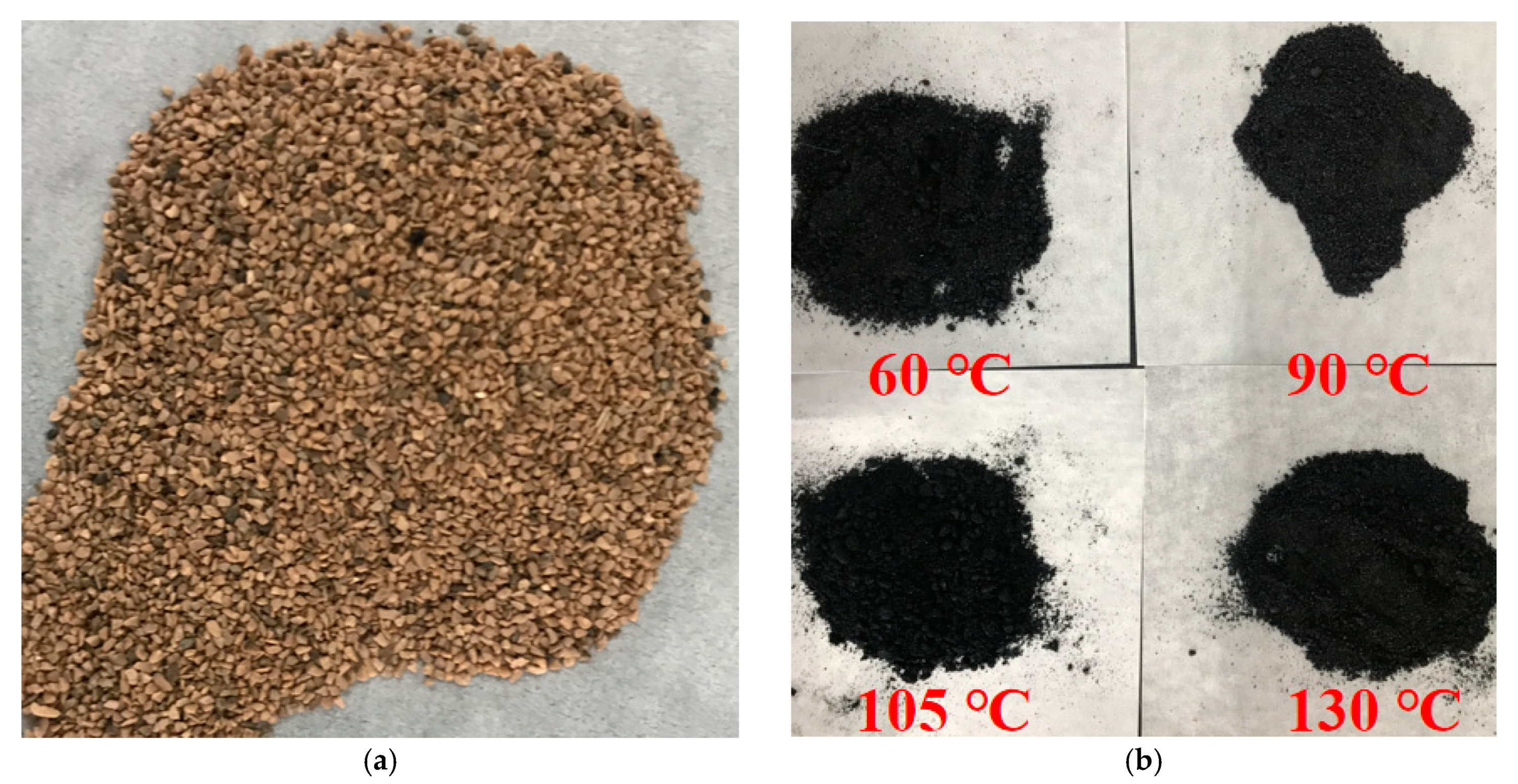
Figure 1. The left is the rigid particle, and the right are the asphalt with different softening points: (a) rigid particle; (b)asphalt with different softening points.
Energies 12 04766 g001
Figure 2. The inside and outside structure of simulated fractured core: (a) Inside network structure of fractured core; (b) Outside structure of fractured core.
Energies 12 04766 g002
Figure 3. Flow chart of core-displacement experiment in high-temperature.
Energies 12 04766 g003
Figure 4. The asphalt-rigid particles system applied to anti gas-channeling in high-temperature and high-salinity environment (here the thickener is xanthan gum).
Energies 12 04766 g004
Figure 5. The particle size distribution of rigid particles and asphalt: (a) Distribution histogram and accumulation curve of rigid particles; (b) Distribution histogram and accumulation curve of asphalt.
Energies 12 04766 g005
Figure 6. The change of asphalt with different softening point and long-term aging property: (a) The relationship between the asphalt softening point and apparent viscosity; (b) The long-term aging performance of asphalt with different softening points.
Energies 12 04766 g006
Figure 7. The bonding performance of asphalt with different softening points on rigid particles, the top is the system before heating, the bottom is the system after heating, and the softening point from left to right is 60 °C, 90 °C, 105 °C and 130 °C.
Energies 12 04766 g007
Figure 8. The change of particle size of the anti-channeling system before and after high-temperature in different asphalt content, taken HA − 2%A + 8%RP as an example, HA represents heating after (on the contrary, HB represents heating before), 2%A + 8%RP means the test group contains 2 wt% asphalt and 8 wt% rigid particles (the same as below): (a) The change of particle size distribution of anti-channeling system before and after heating; (b) The change of d50 of anti-channeling system before and after heating.
Energies 12 04766 g008
Figure 9. The change of particle size of the anti-channeling system before and after high-temperature in different rigid particle content: (a) The change of particle size distribution of anti-channeling system before and after heating; (b) The change of d50 of anti-channeling system before and after heating.
Energies 12 04766 g009
Figure 10. The change of particle size of the anti-channeling system before and after high-temperature in different softening point (taken HA − 60 °C as an example, HA represents heating after (by contrast, HB represents heating before), 60 °C means the softening point of asphalt in test group): (a) The change of particle size distribution of anti-channeling system before and after heating; (b) The change of d50 of anti-channeling system before and after heating.
Energies 12 04766 g010
Figure 11. Thickeners solubility in high-salinity brine, from left to right are: xanthan gum, AP-P4 and hydrolyzed polyacrylamide (HPAM), respectively, concentrations are all 3000 mg·L−1.
Energies 12 04766 g011
Figure 12. (a) and (b) are the steady-state rheological property of HPAM and xanthan gum, respectively. (c) is the relation curve between the concentration of thickener and consistency coefficient.
Energies 12 04766 g012aEnergies 12 04766 g012b
Figure 13. The apparent viscosity and retention of xanthan gum over different aging times.
Energies 12 04766 g013
Figure 14. Xanthan gum-suspended rigid particles (25 °C, the concentration from left to right is 0.1 wt%, 0.2 wt%, 0.3 wt%, 0.4 wt%, 0.5 wt% and 0.6 wt%).
Energies 12 04766 g014
Figure 15. Xanthan gum suspended rigid particles in high-temperature (130 °C, the xanthan gum concentration from top to bottom is 0.3 wt%, 0.4 wt% and 0.5 wt%, the sampling time from left to right is 4 h, 8 h, 12 h, 16 h, 20 h, 24 h and 28 h): (a) Suspension of rigid particles within 0.3 wt% xanthan gum; (b) Suspension of rigid particles within 0.4 wt% xanthan gum; (c) Suspension of rigid particles within 0.5 wt% xanthan gum.
Energies 12 04766 g015aEnergies 12 04766 g015b
Figure 16. Optimized maximum injected concentration by golden section algorithm (this uniaxial image here is only used to show the experimental sequence and results, and has no other meaning).
Energies 12 04766 g016
Figure 17. The distribution of solid particles in 0.4 wt% xanthan gum solution by optical microscope. (af) are the micromorphology of the bonding system before heating under different fields of view.
Energies 12 04766 g017aEnergies 12 04766 g017b
Figure 18. Schematic representation of boundary layer thickness changing with fluid velocity.
Energies 12 04766 g018
Figure 19. Level trend of rigid particles concentration (brown particle is rigid particles and the black particle is asphalt).
Energies 12 04766 g019
Figure 20. Level trend of asphalt concentration (brown particle is rigid particles and the black particle is asphalt).
Energies 12 04766 g020
Figure 21. Level trend of asphalt softening point.
Energies 12 04766 g021
Figure 22. The blocking ratio in different aging time.
Energies 12 04766 g022
Figure 23. The distribution of anti gas-channeling system in network fractures; black solid in the fracture is asphalt, and the rigid particles are colored brown.
Energies 12 04766 g023
Figure 24. Micromorphology observation of blocking zone. (a) and (b) are the micromorphology of the bonding system under different fields of view when the magnification is 300 times; (c) and (d) are the micromorphology of the bonding system under different fields of view when the magnification is 150 times.
Energies 12 04766 g024
Table 1. Components of simulated brine.
ComponentsNaClNa2SO4CaCl2MgCl2·6H2ONaHCO3Total Salinity
g·L−1181.880.2231.229.700.05223.07
Table 2. Orthogonal experimental factors and levels table.
FactorsRigid Particles Content/wt%Asphalt Content/wt%Asphalt Coftening Point/°C
1(A1)2(B1)2(C1)60
2(A2)4(B2)4(C2)90
3(A3)6(B3)6(C3)105
4(A4)8(B4)8(C4)130
Table 3. The grouping of orthogonal experimental.
No.Rigid Particles Content/%Asphalt Content/%Asphalt Softening Point/°CBlocking Ratio/%
1#2260W1
2#2490W2
3#26105W3
4#28130W4
5#4290W5
6#4460W6
7#46130W7
8#48105W8
9#62105W9
10#64130W10
11#6660W11
12#6890W12
13#82130W13
14#84105W14
15#8690W15
16#8860W16
Table 4. The laboratory results of asphalt - rigid particles system anti gas-channeling performance by means of orthogonal design (V0 and V1 are the gas flow rates measured before and after injecting anti gas-channeling system under the conditions of N2 displacement pressure of 0.25 MPa, V0* and V1* are the gas flow rates measured before and after injecting anti gas-channeling system under the conditions of N2 displacement pressure of 1 MPa. Wi and Wi* are the blocking rate under the N2 displacement pressure of 0.25 MPa and 1MPa which was calculated by Equation (3), and i = 1, 2, 3…15, 16).
No.0.25 MPa1 MPa0.25 MPa1 MPa
V0/(L·min−1)V1/(L·min−1)V0*/(L·min−1)V1*/(L·min−1)Wi/%Wi*/%
1#25.8520.3476.7361.6821.3219.61
2#25.1518.7674.9157.5225.4223.21
3#24.3217.7575.6256.9627.0124.67
4#24.6617.5675.1955.4728.7826.23
5#25.1611.8176.0339.3053.0848.31
6#25.335.8675.7723.3376.8769.21
7#26.398.8876.5230.5566.3460.08
8#26.868.6875.1929.1167.6761.29
9#26.5710.2576.2834.0961.4355.31
10#25.737.3075.2326.0871.6465.33
11#26.0413.3376.4042.3648.8244.56
12#24.735.9775.6123.4275.8669.02
13#25.6111.7276.2137.8654.2350.32
14#25.228.2175.3128.7867.4361.79
15#25.013.2875.4415.2584.9079.79
16#25.774.0776.0917.4984.2277.02
Table 5. Evaluating indicators of three factors and four levels (ki refers to the ratio of the sum of the corresponding test results when the number of level on any column is i (i = 1, 2, 3, 4 in this study) to the occurrence times (4 times in this study) of each level on any column (for example, for the Factor B, its k1-0.25MPa = (W1 + W5 + W9 + W13)/4 and k2-0.25MPa = (W2 + W6 + W10 + W14)/4). Range refers to the variation range of the test index within the value range of a factor (the algorithm is max{k1, k2, k3, k4}min{k1, k2, k3, k4}, for example, for the Factor A, its R0.25MPa = k4-0.25MPa − k1-0.25MPa and its R1MPa = k4-1MPa – k1-1MPa).
FactorsABC
kik1-0.25MPa25.63347.51557.807
k1-1MPa19.63543.38852.600
k2-0.25MPa65.99060.34060.315
k2-1MPa58.61754.88555.083
k3-0.25MPa64.43857.26855.885
k3-1MPa56.58052.27550.765
k4-0.25MPa73.19564.13255.247
k4-1MPa65.47258.39050.490
Range R0.25MPa47.56216.6175.068
Range R1MPa45.83715.0024.593
Major-minor sequence123
Optimal schemeA4B4C2
Table 6. Blocking effect of optimal scheme (The meanings of each notations are the same as in Table 4).
0.25 MPa1 MPa0.25 MPa1 MPa
V0/((L·min−1)V1/(L·min−1)V0*/(L·min−1)V1*/(L·min−1)W/%W*/%
25.492.2976.7310.5691.0286.24