A Novel Lithium Battery Equalization Circuit with Any Number of Inductors


Abstract
:
1. Introduction
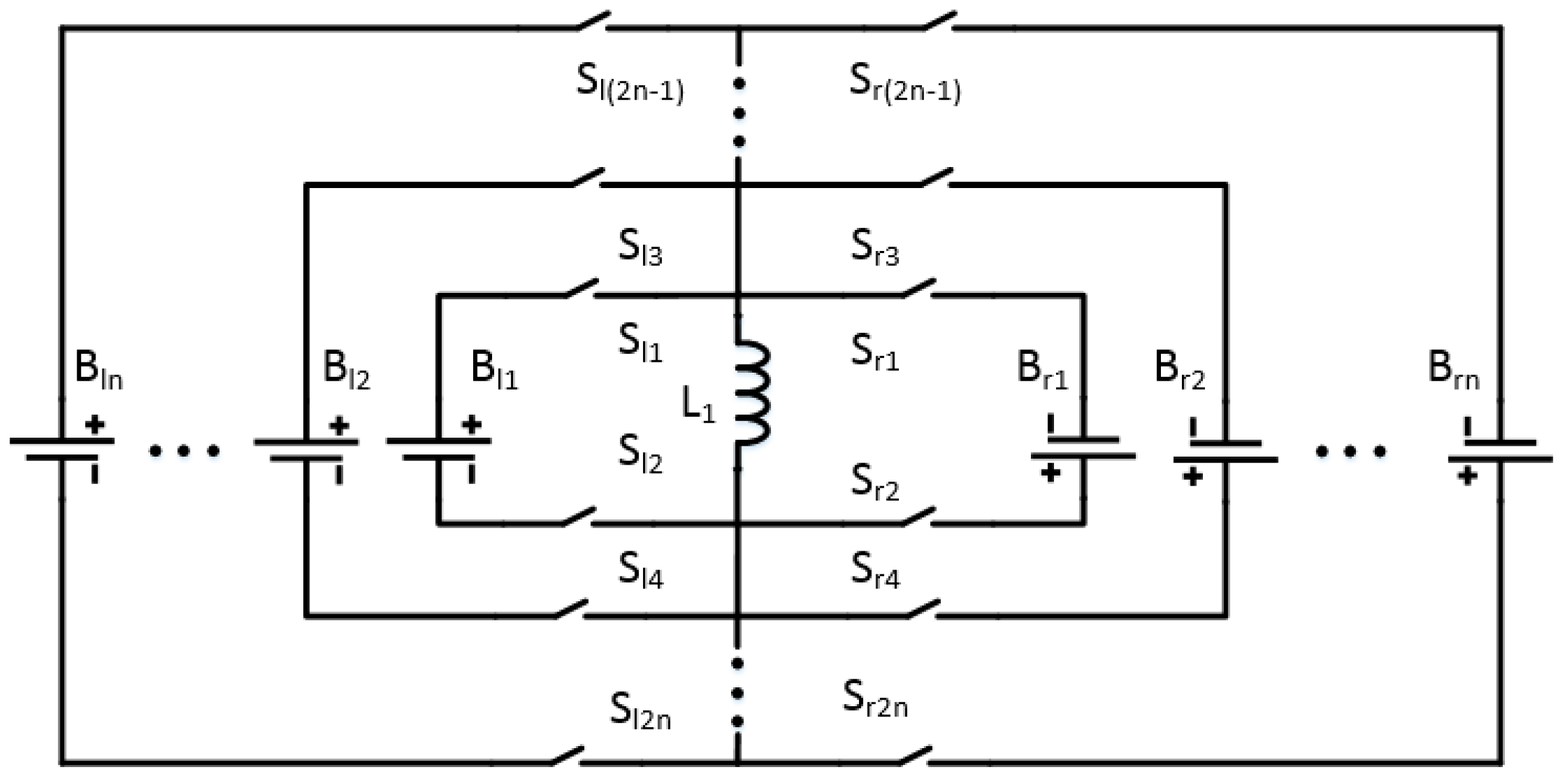
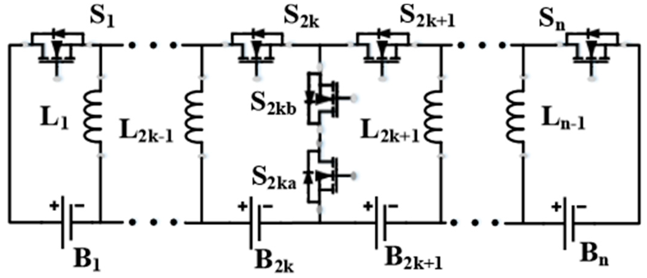
2. The Structure of The ECANI
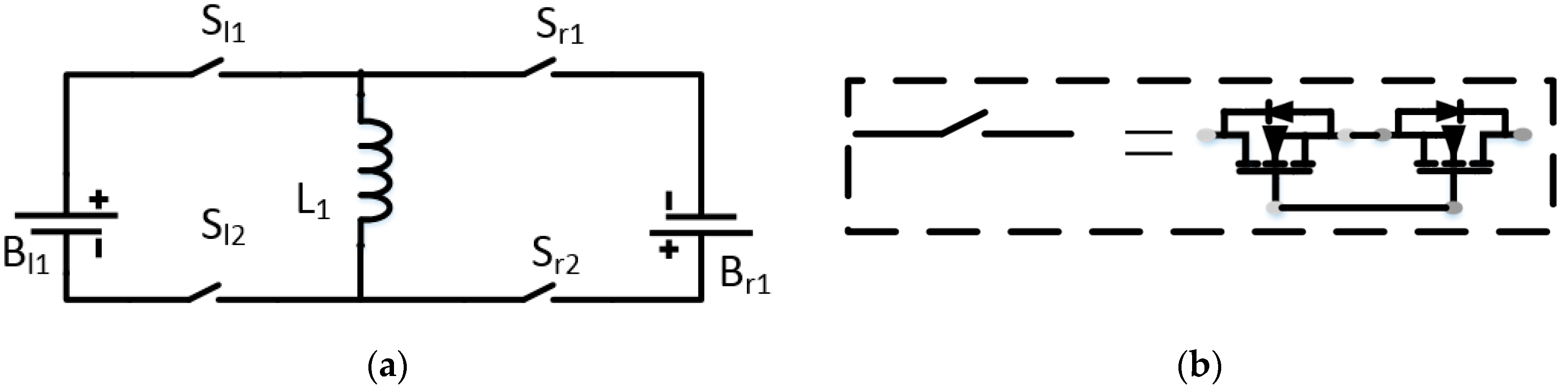
2.1. Two Cells Equalization Circuit
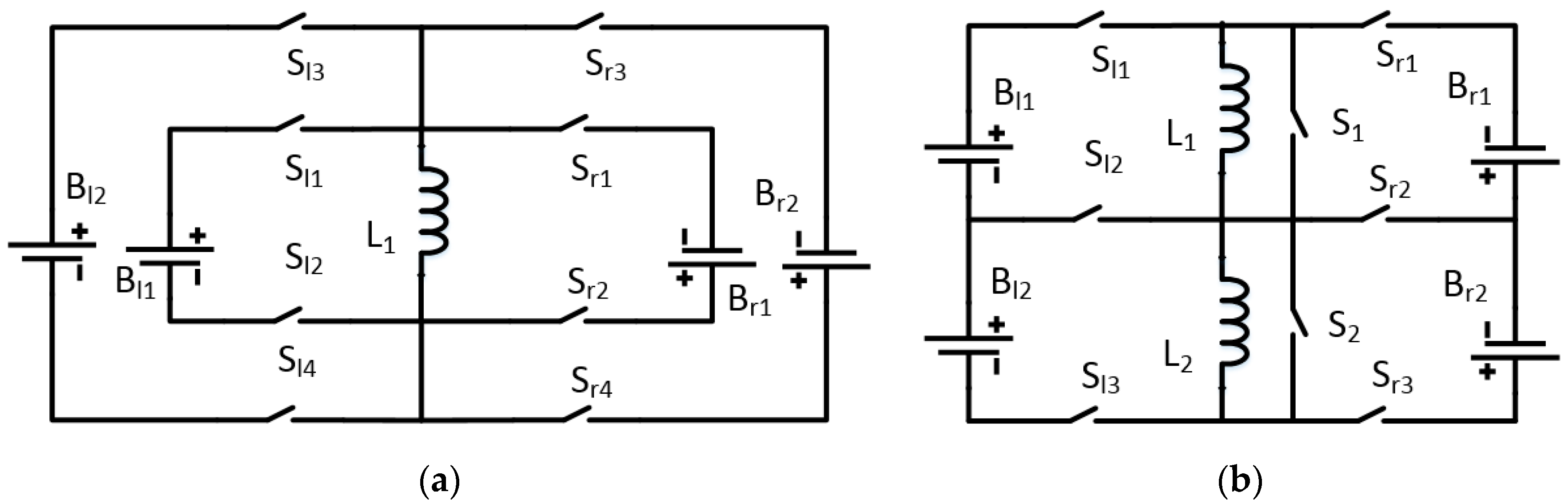
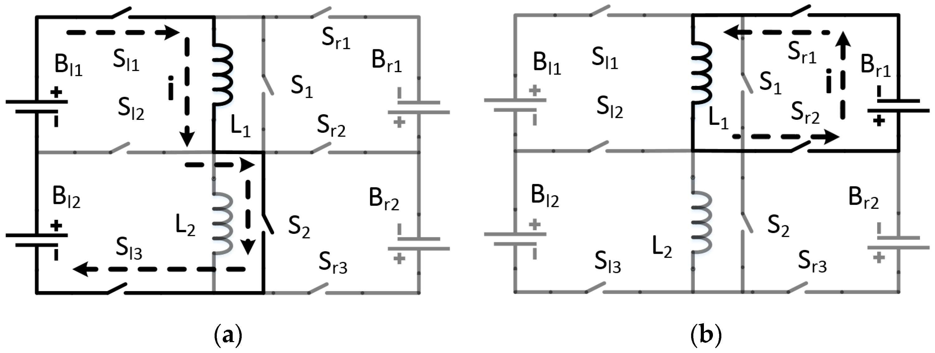
2.2. Four Cells Equalization Circuit
2.3. Eight Cells Equalization Circuit
3. Simulation
3.1. Equalization Simulation with Four Cells
3.2. Equalization Simulation with Eight Cells
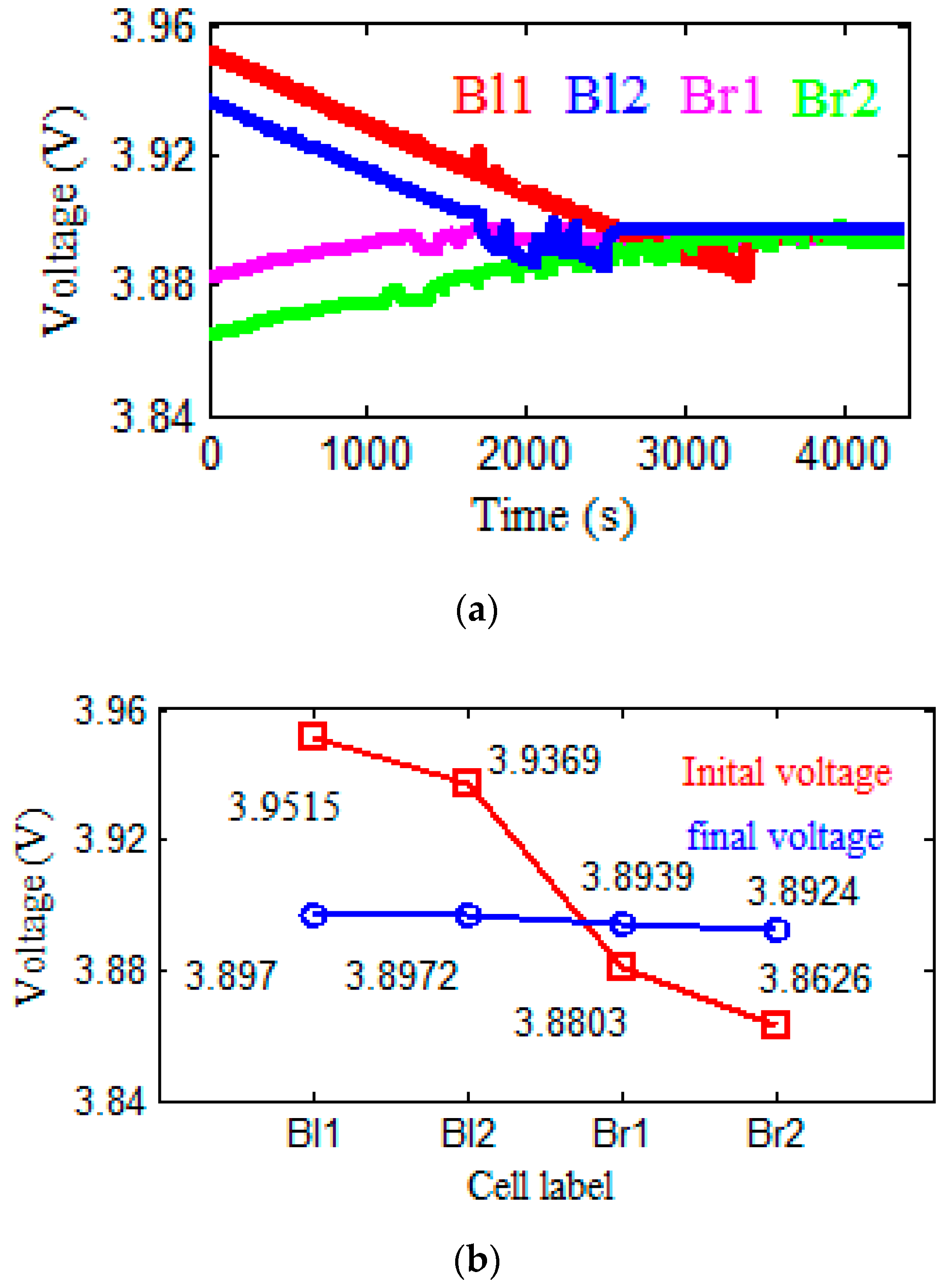
4. Experimental Results and Discussion
5. Conclusions
Author Contributions
Funding
Acknowledgments
Conflicts of Interest
References
- Ye, Y.; Cheng, K.W.E.; Fong, Y.C.; Xue, X.; Lin, J. Topology, Modeling, and Design of Switched-Capacitor-Based Cell Balancing Systems and Their Balancing Exploration. IEEE Trans. Power Electron. 2017, 32, 4444–4454. [Google Scholar] [CrossRef]
- Gallardo-Lozano, J.; Romero-Cadaval, E.; Milanes-Montero, M.I.; Guerrero-Martinez, M.A. Battery equalization active methods. J. Power Sources 2014, 246, 934–949. [Google Scholar] [CrossRef]
- Yuanmao, Y.; Cheng, K.W.E.; Yeung, Y.P.B. Zero-Current Switching Switched-Capacitor Zero-Voltage-Gap Automatic Equalization System for Series Battery String. IEEE Trans. Power Electron. 2012, 27, 3234–3242. [Google Scholar] [CrossRef]
- Lu, C.; Kang, L.; Wang, S.; Wang, Z.; Rao, H. A Novel Inductor-Based Non-Dissipative Equalizer. Energies 2018, 11, 2816. [Google Scholar] [CrossRef] [Green Version]
- Lee, S.; Lee, K.; Choi, Y.; Kang, B. Modularized Design of Active Charge Equalizer for Li-Ion Battery Pack. IEEE Trans. Ind. Electron. 2018, 65, 8697–8706. [Google Scholar] [CrossRef]
- Yarlagadda, S.; Hartley, T.T.; Husain, I. A Battery Management System Using an Active Charge Equalization Technique Based on a DC/DC Converter Topology. IEEE Trans. Ind. Appl. 2013, 49, 2720–2729. [Google Scholar] [CrossRef]
- Zhou, Z.; Shang, Y.; Duan, B.; Zhang, C. An Any-Cell(s)-to-Any-Cell(s) Equalizer Based on Bidirectional Inductor Converters for Series Connected Battery String. In Proceedings of the IEEE 11th Conference on Industrial Electronics and Applications (ICIEA), Hefei, China, 5–7 June 2016; pp. 2511–2515. [Google Scholar]
- Wang, S.; Kang, L.; Guo, X.; Wang, Z.; Liu, M. A Novel Layered Bidirectional Equalizer Based on a Buck-Boost Converter for Series-Connected Battery Strings. Energies 2017, 10, 1011. [Google Scholar] [CrossRef]
- Guo, X.; Kang, L.; Huang, Z.; Yao, Y.; Yang, H. Research on a Novel Power Inductor-Based Bidirectional Lossless Equalization Circuit for Series-Connected Battery Packs. Energies 2015, 8, 5555–5576. [Google Scholar] [CrossRef]
- Shang, Y.; Xia, B.; Zhang, C.; Cui, N.; Yang, J.; Mi, C.C. An Automatic Equalizer Based on Forward–Flyback Converter for Series-Connected Battery Strings. IEEE Trans. Ind. Electron. 2017, 64, 5380–5391. [Google Scholar] [CrossRef]
- Dong, B.; Li, Y.; Han, Y. Parallel Architecture for Battery Charge Equalization. IEEE Trans. Power Electron. 2015, 30, 4906–4913. [Google Scholar] [CrossRef]
- Liu, J.; Xu, M.; Zeng, J.; Wu, J.; Kai Wai Eric, C. Modified voltage equaliser based on Cockcroft–Walton voltage multipliers for series-connected supercapacitors. IET Electr. Syst. Transp. 2018, 8, 44–51. [Google Scholar] [CrossRef]
- Lee, Y.S.; Cheng, G.T. Quasi-Resonant Zero-Current-Switching Bidirectional Converter for Battery Equalization Applications. IEEE Trans. Power Electron. 2006, 21, 1213–1224. [Google Scholar] [CrossRef]
- Kirshenboim, O.; Peretz, M.M.; Zeltser, I. Non-isolated parallel balancing converter for serially connected batteries string. In Proceedings of the 2017 IEEE Applied Power Electronics Conference and Exposition (APEC), Tampa, FL, USA, 26–30 March 2017; pp. 1236–1241. [Google Scholar]
- Zhang, Z.; Gui, H.; Gu, D.; Yang, Y.; Ren, X. A Hierarchical Active Balancing Architecture for Lithium-Ion Batteries. IEEE Trans. Power Electron. 2017, 32, 2757–2768. [Google Scholar] [CrossRef]
- Baughman, A.C.; Ferdowsi, M. Double-Tiered Switched-Capacitor Battery Charge Equalization Technique. IEEE Trans. Power Electron. 2008, 55, 2277–2285. [Google Scholar] [CrossRef]
- Din, E.; Schaef, C.; Moffat, K.; Stauth, J.T. A Scalable Active Battery Management System with Embedded Real-Time Electrochemical Impedance Spectroscopy. IEEE Trans. Power Electron. 2017, 32, 5688–5698. [Google Scholar] [CrossRef]
- Lu, L.; Han, X.; Li, J.; Hua, J.; Ouyang, M. A review on the key issues for lithium-ion battery management in electric vehicles. J. Power Sources 2013, 226, 272–288. [Google Scholar] [CrossRef]
- Rahimi-Eichi, H.; Ojha, U.; Baronti, F.; Chow, M. Battery Management System: An Overview of Its Application in the Smart Grid and Electric Vehicles. IEEE Ind. Electron. Mag. 2013, 7, 4–16. [Google Scholar] [CrossRef]
- Velho, R.; Beirão, M.; Calado, M.; Pombo, J.; Fermeiro, J.; Mariano, S. Management System for Large Li-Ion Battery Packs with a New Adaptive Multistage Charging Method. Energies 2017, 10, 605. [Google Scholar] [CrossRef]
- Hongyu, A.W.; Yupeng, B.Y.; Chuamg, C.M. A Modeling Method of Whole Vehicle Electrical Balance Simulation System Based on Neural Network Training. IFAC-PapersOnLine 2018, 51, 87–91. [Google Scholar] [CrossRef]
- Li, S.; Mi, C.C.; Zhang, M. A High-Efficiency Active Battery-Balancing Circuit Using Multiwinding Transformer. IEEE Trans. Ind. Appl. 2013, 49, 198–207. [Google Scholar] [CrossRef]
- Bi, K.; Sun, L.; An, Q.; Duan, J. Active SOC Balancing Control Strategy for Modular Multilevel Super Capacitor Energy Storage System. IEEE Trans. Power Electron. 2019, 34, 4981–4992. [Google Scholar] [CrossRef]
- Bouchhima, N.; Schnierle, M.; Schulte, S.; Birke, K.P. Active model-based balancing strategy for self-reconfigurable batteries. J. Power Sources 2016, 322, 129–137. [Google Scholar] [CrossRef]
- Yang, Y.; Zhang, Z.; Gu, D.; Cheng, X. In Balancing strategy of lithium-ion batteries based on change rate of SOC. In Proceedings of the 2017 IEEE Applied Power Electronics Conference and Exposition (APEC), Tampa, FL, USA, 26–30 March 2017; pp. 3223–3228. [Google Scholar]
- Gallardo-Lozano, J.; Romero-Cadaval, E.; Milanes-Montero, M.I.; Guerrero-Martinez, M.A. A novel active battery equalization control with on-line unhealthy cell detection and cell change decision. J. Power Sources 2015, 299, 356–370. [Google Scholar] [CrossRef]
- Kuchak, S.V.; Voroshilov, A.N. Charge characteristics of lithium-ion accumulators under different voltages. In Proceedings of the 2016 17th International Conference of Young Specialists on Micro/Nanotechnologies and Electron Devices (EDM), Erlagol, Russia, 30 June–4 July 2016; pp. 484–485. [Google Scholar]


| Structure | Cells | Inductors | Switches |
|---|---|---|---|
| The ECANI 2-1 | 2 | 1 | 4 |
| The ECANI 4-1 | 4 | 1 | 8 |
| The ECANI 4-2 | 4 | 2 | 8 |
| The ECANI 8-1 | 8 | 1 | 16 |
| The ECANI 8-2 | 8 | 2 | 14 |
| The ECANI 8-3 | 8 | 3 | 14 |
| The ECANI 8-4 | 8 | 4 | 14 |
| The ECANI n-m | n | m | (m + n + 1)–2n |
| Platform | Battery | Switching Frequency | Duty Cycle | Inductance | Parasitic Capacitances and Parasitic Inductances |
|---|---|---|---|---|---|
| PSIM (Power Simulation) 9.0 | Substituted by 1 F capacitor | 10 kHz | 20%, 40%, 60% | 100 μH | ignored |
| Cell Label | Bl1 | Bl2 | Br3 | Br4 |
|---|---|---|---|---|
| Voltage | 3.99 | 3.961 | 3.91 | 3.896 |
| Cell Label | Bl1 | Bl2 | Bl3 | Bl4 | Br1 | Br2 | Br3 | Br4 |
|---|---|---|---|---|---|---|---|---|
| Voltage | 3.99 | 3.975 | 3.961 | 3.945 | 3.93 | 3.92 | 3.91 | 3.896 |
| The ECANI 8-1 | The ECANI 8-2 | The ECANI 8-3 | The ECANI 8-4 | |
|---|---|---|---|---|
| Time | 1.2163 | 0.4356 | 0.2753 | 0.2594 |
| Parameters | Component | Label | Value | Value |
|---|---|---|---|---|
| Battery string | Samsung lithium battery | ,,, | 2.2 Ah | - |
| Circuit | MOSFET | –,–,– | IRF3205PBF | |
| - | Inductor | , | 100.1 , 100.5 |
© 2019 by the authors. Licensee MDPI, Basel, Switzerland. This article is an open access article distributed under the terms and conditions of the Creative Commons Attribution (CC BY) license (http://creativecommons.org/licenses/by/4.0/).
Share and Cite
Lu, C.; Kang, L.; Luo, X.; Linghu, J.; Lin, H. A Novel Lithium Battery Equalization Circuit with Any Number of Inductors. Energies 2019, 12, 4764. https://doi.org/10.3390/en12244764
Lu C, Kang L, Luo X, Linghu J, Lin H. A Novel Lithium Battery Equalization Circuit with Any Number of Inductors. Energies. 2019; 12(24):4764. https://doi.org/10.3390/en12244764
Chicago/Turabian StyleLu, Chusheng, Longyun Kang, Xuan Luo, Jinqing Linghu, and Hongye Lin. 2019. "A Novel Lithium Battery Equalization Circuit with Any Number of Inductors" Energies 12, no. 24: 4764. https://doi.org/10.3390/en12244764
APA StyleLu, C., Kang, L., Luo, X., Linghu, J., & Lin, H. (2019). A Novel Lithium Battery Equalization Circuit with Any Number of Inductors. Energies, 12(24), 4764. https://doi.org/10.3390/en12244764