Article

Finite Control Set Model Predictive Control of Six-Phase Asymmetrical Machines—An Overview

Department of Electrical and Computer Engineering, University of Coimbra, and Instituto de Telecomunicações, Pólo 2-Pinhal de Marrocos, P-3030-290 Coimbra, Portugal
*
Author to whom correspondence should be addressed.
Energies 2019, 12(24), 4693; https://doi.org/10.3390/en12244693
Submission received: 29 October 2019 / Revised: 27 November 2019 / Accepted: 5 December 2019 / Published: 10 December 2019
(This article belongs to the Special Issue Advances in Rotating Electric Machines)

Abstract

:
Recently, the control of multiphase electric drives has been a hot research topic due to the advantages of multiphase machines, namely the reduced phase ratings, improved fault tolerance and lesser torque harmonics. Finite control set model predictive control (FCS-MPC) is one of the most promising high performance control strategies due to its good dynamic behaviour and flexibility in the definition of control objectives. Although several FCS-MPC strategies have already been proposed for multiphase drives, a comparative study that assembles all these strategies in a single reference is still missing. Hence, this paper aims to provide an overview and a critical comparison of all available FCS-MPC techniques for electric drives based on six-phase machines, focusing mainly on predictive current control (PCC) and predictive torque control (PTC) strategies. The performance of an asymmetrical six-phase permanent magnet synchronous machine is compared side-by-side for a total of thirteen PCC and five PTC strategies, with the aid of simulation and experimental results. Finally, in order to determine the best and the worst performing control strategies, each strategy is evaluated according to distinct features, such as ease of implementation, minimization of current harmonics, tuning requirements, computational burden, among others.

Graphical Abstract

1. Introduction

Rotating electrical machines with a number of phases higher than three ( n > 3 ) are commonly referred to in the literature as multiphase machines [1]. Multiphase machines were first used in high power generation units during the 1920s due to the current limit of circuit breakers at that time and due to the size of the reactors needed to limit currents in the event of faults [2]. In the 1960s, it was demonstrated that an increase in the number of phases of electrical machines fed by voltage source inverters (VSIs) leads to an increase of the order of torque pulsations ( h = 2 n ) and to a reduction of their magnitude [3]. Additionally, the increase in the number of phases also leads to a lower current or voltage per phase, decreasing the requirements of the power semiconductors ratings [4]. An electric drive with improved reliability based on a multiphase machine was first studied in the 1980s [5], where each phase was connected to an independent power converter and in the event of a fault in one or more phases, the drive could remain in operation with a reduced power rating. Since the decoupled control of flux and torque in multiphase machines only requires the regulation of two independent current components, regardless of the number of phases of the machine [6], multiphase machines provide additional degrees of freedom that can be used for several purposes without affecting the production of flux and torque [7]. The first works taking advantage of the additional degrees of freedom of multiphase machines were published in the 1990s, where the injection of current harmonics was used to enhance the torque developed by machines with concentrated windings [8,9]. Multimotor drives proposed in the 2000s is another application that takes advantage of the additional degrees of freedom, where a single n-phase VSI is able to drive independently up to n 1 / 2 machines if n is odd or up to n 2 / 2 machines if n is even, either connected in series or in parallel [10,11]. More recently, the additional degrees of freedom of multiphase machines are being used to provide: balancing of the dc-link capacitors of series-connected VSIs on the machine side [12]; unequal power sharing [13,14]; full-load test methods [15,16]; integrated battery charging for electric vehicles [17,18,19]; dynamic braking for non-regenerative electric drives [20,21]; and diagnosis of open-phase faults [22,23]. In addition to the reduced current or voltage ratings per phase, lower torque harmonics, improved fault-tolerant capabilities and additional degrees of freedom, multiphase machines also offer other advantages over their three-phase counterparts, namely: improved winding factors, reduced harmonic content in the magnetomotive force (MMF), lower rotor losses and lesser harmonics in the dc-link current [1,24,25,
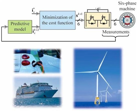
26]. Nowadays, electric drives based on multiphase machines are employed in a wide range of areas, such as aircraft [27,28], electric or hybrid vehicles [29], locomotive traction [30], high-speed elevators [31], ship propulsion [32], spacecraft [33] and wind energy applications [34,35,36].
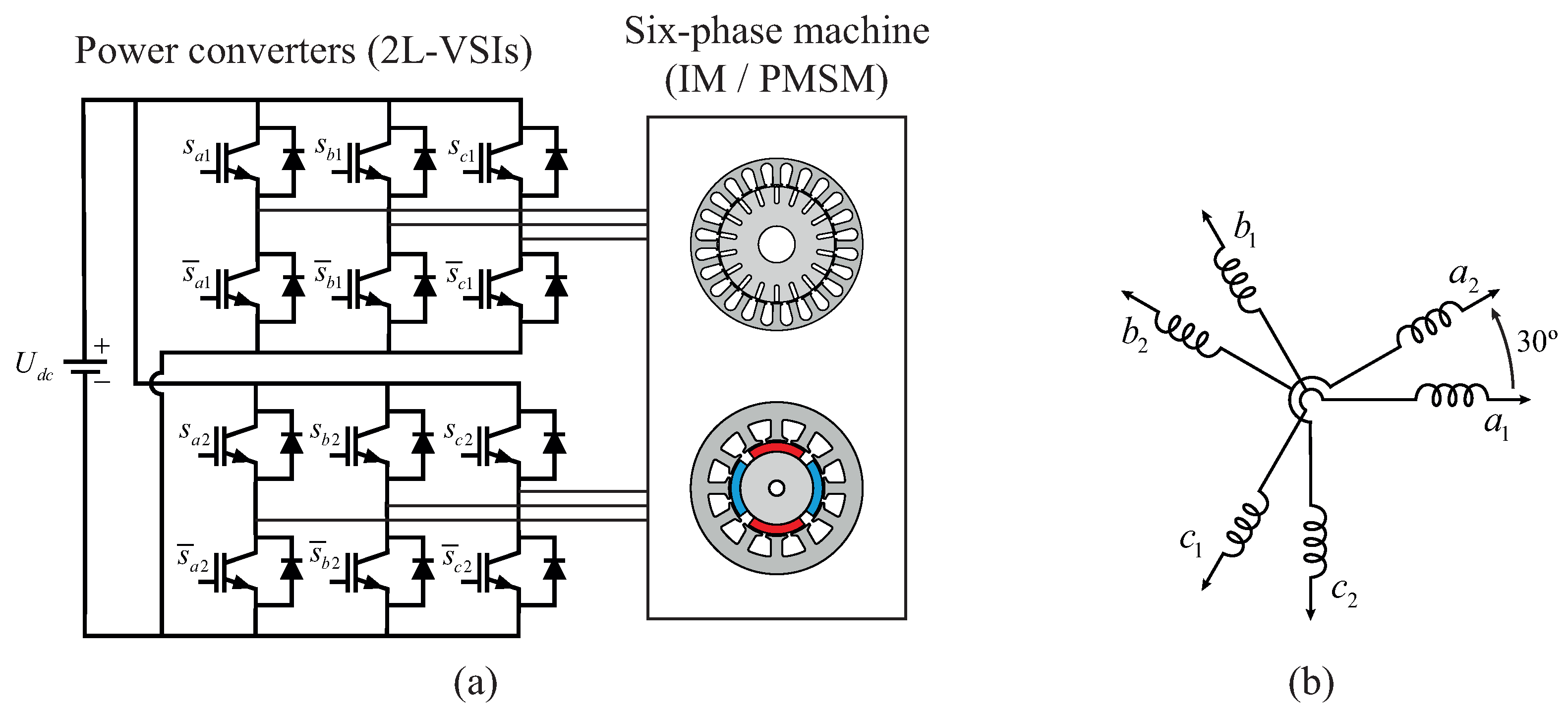
In multiphase electric drives, n-phase machines are typically supplied by a n-phase VSI, whose power semiconductors are commanded by a control strategy in order to achieve variable speed operation [26]. Several control strategies have been reported in the literature over the years for multiphase electric drives, such as scalar or constant V / f control, field oriented control (FOC) and direct torque control (DTC) [25,26]. Scalar control regulates the speed of the machine by imposing a constant ratio between the amplitude and the frequency of the stator voltage [3]. Since the constant V / f control cannot control directly the currents, an unbalance in the machine can lead to the appearance of x-y current components with considerable magnitude [37]. Moreover, the reference voltages generated by scalar control are translated into command signals for the power semiconductors of the VSI using pulse width modulation (PWM) or space vector PWM (SV-PWM) techniques [7]. However, similarly to standard three-phase electric drives, scalar control cannot provide accurate control of the rotor speed of multiphase machines and leads to a poor dynamic performance [25]. On the other hand, both FOC and DTC schemes provide a decoupled control of the flux and torque, improving the control of the machine [38]. Typically, in FOC schemes the flux and torque of the machine are adjusted by regulating two independent current components with proportional-integral (PI) controllers, regardless of the number of phases of the machine, and the VSI control signals are synthesized with PWM or SV-PWM techniques [39,40]. In the case of DTC schemes, the flux and torque are controlled directly with hysteresis controllers and the control actuation is usually selected using a switching table [41,42].
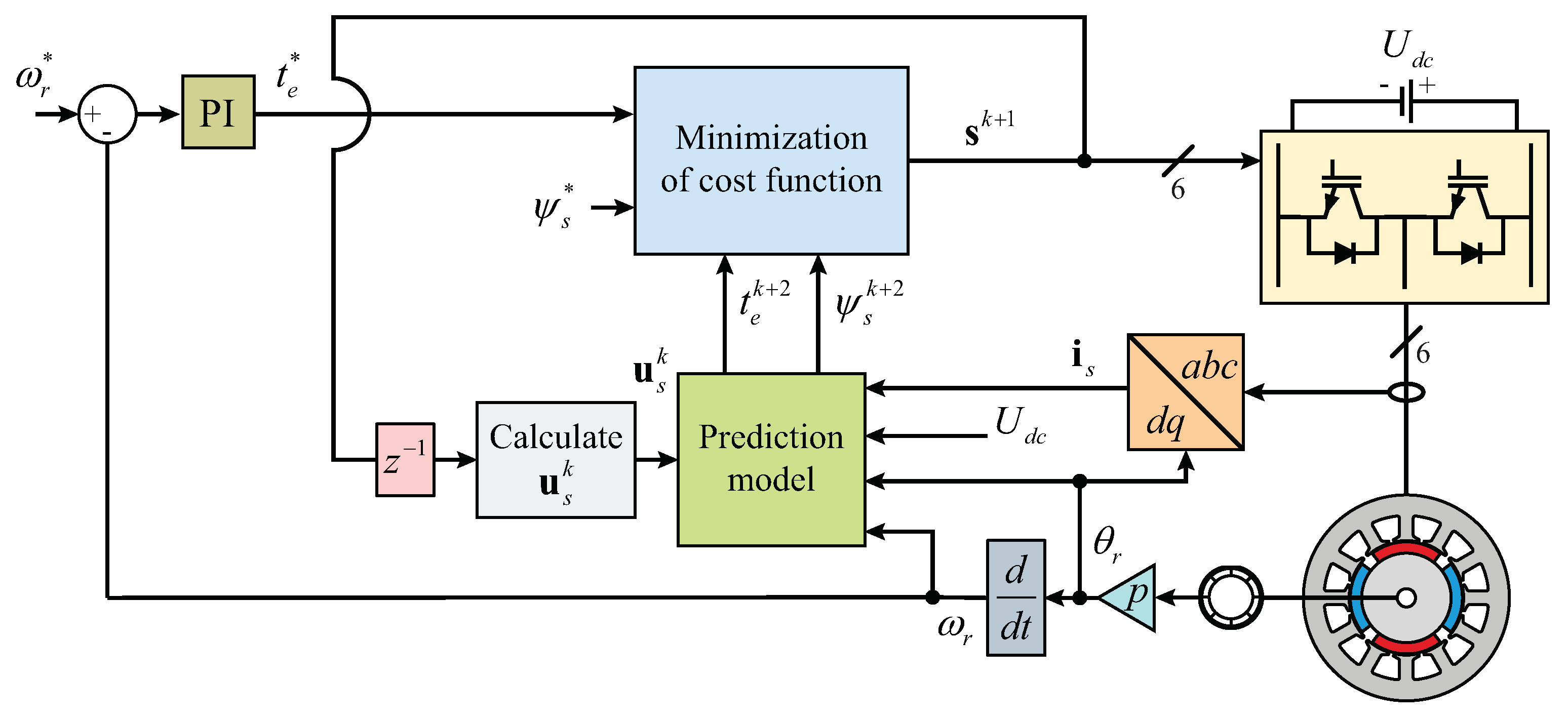
In the last decade, finite control set model predictive control (FCS-MPC), along with control strategies such as FOC and DTC, has been proposed for the control of high-performance electric drives [43,44,45]. The main advantages of FCS-MPC over the classical control strategies are the improved dynamic performance, flexibility in the definition of control objectives and easy inclusion of constraints [46]. Since SV-PWM techniques can be hard to implement in multiphase drives [7], particularly for machines with a high number of phases or when multilevel converters are employed, FCS-MPC is also an attractive solution for multiphase drives since it does not require the use of a modulator [46]. FCS-MPC strategies use a discrete version of the system model to predict the future behavior of the controlled variables, considering a finite set of possible actuations of the power converters [47]. Typically, FCS-MPC strategies can be based on the application of a single switching state during a sampling period, referred to as optical switching vector MPC (OSV-MPC), or as an alternative, consider the application of an optimal switching sequence, known as optimal switching sequence (OSS-MPC) [48]. The control objectives of the FCS-MPC strategies are expressed in the form of a cost function, which evaluates the error between the controlled variables and their reference values. Hence, the optimal actuation is obtained by selecting, among the considered finite set of control actuations the one that leads to the minimum value of the cost function [46,47,48].
The FCS-MPC strategies available in the literature for multiphase drives are commonly classified according to their control objectives, such as predictive current control (PCC), predictive torque control (PTC) or predictive speed control (PSC) [49]. In the case of PCC schemes, the stator currents are the controlled variables, while the flux and torque are usually selected as the controlled variables in PTC strategies [50]. The PSC scheme eliminates the external PI speed loop present in PCC and PTC strategies although it requires the tuning of several weighting factors and depends on the mechanical parameters of the drive to estimate the load torque and predict the rotor speed [51]. Due to these limitations of PSC schemes, applications of both PCC and PTC strategies for multiphase drives are more popular among the research community and can be found in multiple publications [49,50,52,53,54,55].
Although several works have reported implementations of FCS-MPC strategies for electric drives based on multiphase machines in recent years, very few works attempted to review and compare these control strategies [50]. The publications [43,50,56,57] provide an overview of FCS-MPC strategies applied to five and six-phase machines, which are the simplest and the most addressed configurations in the literature [58]. However, these publications do not provide simulation or experimental results and lack a critical comparison among the considered FCS-MPC control strategies. On the other hand, a comparison between several FCS-MPC strategies applied to a six-phase PMSM drive was presented in Reference [49], although only simulation results were provided and the latest contributions in this field are missing.
This paper assembles in a single reference all published FCS-MPC strategies for electric drives based on six-phase machines. It presents a critical comparative study between the different FCS-MPC strategies, highlighting their advantages and drawbacks, being supported by a theoretical framework and by both simulation and experimental results obtained with a six-phase PMSM drive. Additionally, the paper includes a section providing an overview of the different topologies of multiphase electric drives and a section detailing the modeling of six-phase machine drives.
The paper is structured as follows—Section 2 provides an overview of the existing multiphase electric drives, Section 3 discusses the modeling of six-phase drives and Section 4 presents the theory behind the FCS-MPC strategies for the six-phase drives published so far. Moreover, Section 5 presents the simulation results of the reviewed FCS-MPC strategies, while Section 6 presents the experimental results for the same control strategies. Finally, Section 7 contains the main conclusions of this work.

2. Multiphase Electric Drives

Since n-phase machines are supplied by n-phase power converters in multiphase electric drives, the variable n is not restricted by the number of phases of the electric grid and can be selected according to the application [26]. Hence, this section provides an overview of the different types of n-phase machines and n-phase power converters reported in the literature. Since this paper provides an overview of the FCS-MPC strategies for six-phase drives ( n = 6 ) in particular, this topology is analyzed in more detail in Section 2.3.

2.1. Types of Multiphase Electric Machines

The main difference between multiphase and standard three-phase machines is the configuration of the stator windings [58]. In multiphase machines, the stator windings are designed to have n phases and can be of distributed or concentrated type, depending on the number of stator slots per pole per phase [25]. Regarding the machine type in multiphase drives, the majority of the literature published in recent years has been focused on induction machines (IMs) and permanent magnet synchronous machines (PMSMs) [50,59]. In comparison to IMs, PMSMs provide a higher efficiency and power density, higher power factor and enhanced fault tolerance against open-phase faults [58,60].
Multiphase machines are typically classified according to the spatial displacement between phases and are denominated as symmetrical or asymmetrical machines [58]. In the symmetrical configuration, the stator windings of a n-phase machine are designed to have a displacement of 360 / n electrical degrees between consecutive phases [61]. However, if n is an odd and non-prime number or if n is an even number, that is, n = 6 , 9 , 12 , 15 , , the stator windings of a n-phase machine can also be designed to have an asymmetrical configuration. In the asymmetrical configuration, the stator windings are associated in k sets of windings, each one with a phases ( n = a · k ) spaced by 360 / a electrical degrees and the k sets of windings are displaced by α = 180 / n electrical degrees between them [62]. In the symmetrical configuration, the n-phases are usually wye-connected with a single neutral point, whereas in the asymmetrical configuration the a phases within each set of windings are wye-connected with k neutral points, which can be left isolated or connected to each other [59].
The asymmetrical configuration with k isolated neutral points is widely adopted since it restricts the circulation of zero-sequence currents (ZSC) [63] and provides isolation among the k sets of windings [26], although the number of independent currents is reduced to from n 1 to n k in comparison with the single neutral point case [25]. Since the k sets of windings are isolated from each other, the use of coupling inductors is not necessary as in the case of high-power three-phase machines, where several power converters are associated in parallel to achieve high power ratings [60]. In the case of a fault in either the converter or the machine, a simple fault-tolerant control strategy can be adopted for machines with n = a · k phases and k isolated neutrals by simply deactivating the affected set of windings, while the drive is maintained in operation with a reduction in the power rating of 1 / k × 100 % [26]. On the other hand, the asymmetrical configuration with a single neutral configuration has additional k 1 degrees of freedom, resulting in improved performance under fault-tolerant operation [62,64,65].
The majority of multiphase machines with an asymmetrical configuration are designed to have multiple sets of three-phase windings ( a = 3 ) in order to maintain the compatibility with standard three-phase power converters [59,66]. Examples of application of these multiphase machines are the six-phase ( k = 2 ) and twelve-phase generators ( k = 4 ) used in wind energy applications [67], and the nine-phase machine used in high-speed elevators [31]. Although less common, the sets of windings can be arranged with a number of phases different from three, such as the fifteen-phase machine with three sets of five-phase windings ( a = 5 ) reported in Reference [58] for a ship propulsion system.

2.2. Types of Power Converters

The n-phase power converters employed in multiphase drives can be of two types: n-phase VSIs or n-phase current source inverters (CSIs). Nowadays, n-phase VSIs are usually adopted in multiphase drives [58], while CSIs were used in some of the earlier multiphase drives [68,69]. Typically, two-level voltage source inverters (2L-VSIs) are used to drive multiphase machines in industrial applications, although multilevel topologies, such as the neutral-point-clamped (3L-NPC) converter can also be employed [7,70]. Other topologies of multiphase VSIs referred in the literature are the n-phase matrix converter and the n-phase H-bridge converter [26,66].
Multiphase power converters can be associated to supply the machine from one side or from both sides, being usually denominated as single or double-sided supply [7]. The single-sided configuration is the one typically employed in multiphase drives, since the stator windings in multiphase phase machines are commonly wye-connected into one or multiple stars [26]. In the double-sided configuration, the stator windings of the machine are supplied from both sides in an open winding configuration, increasing the number of levels of the phase voltage supplied by the VSIs and improving the fault-tolerant performance of the system [7,58]. However, the double-sided supply configuration requires twice the number of VSIs used in the single-sided configuration, increasing the complexity of the electric drive.
Typically, n-phase machines with multiple sets of a-phase windings ( n = a · k ) are supplied from k VSIs, each one with a phases [59]. These k VSIs can be arranged into three configurations regarding the dc-link side: (i) a single dc-link; (ii) k isolated dc-links; (iii) k series-connected dc-links [58]. In healthy operation, both the single dc-link and the k isolated dc-links provide similar performance, the only difference is in fault-tolerant operation where the single dc-link provides better capabilities [71,72,73]. In spite of elevating the total dc-link voltage, the use of k series-connected dc-links requires a control strategy to guarantee the balance of the voltage of the dc-link capacitors and performs worse than the other configurations in fault-tolerant operation [12].

2.3. Particular Case: Six-Phase Drives

Among multiphase machines with multiple sets of three-phase windings, the asymmetrical six-phase machine with two isolated neutrals (2N) is the simplest and the most studied configuration [1,25,26,50,58,59,74]. In the literature, six-phase machines are also referred to as dual three-phase, dual-stator, double-star, quasi six-phase or split-phase machines [25,38]. The diagram of a typical six-phase drive is presented in Figure 1, where a six-phase machine (either an IM or a PMSM) with an asymmetrical winding configuration is supplied by two 2L-VSIs connected to a single dc-link.
Regarding the configuration of the stator windings of six-phase machines, the asymmetrical configuration is the most reported in the literature, where the two sets of three-phase windings are displaced by thirty electrical degrees ( α = 30 ° ), as shown in Figure 1b [58]. The asymmetrical configuration provides a reduction of the MMF harmonic content and eliminates the torque harmonics of order h = 6 · m , with m being an odd number [37,75,76]. Other values for the displacement between the two sets of windings, such as α = 0 ° and α = 60 ° (symmetrical configuration), do not provide a reduction of the harmonic content of the MMF and torque [25,76,77].
Since in six-phase machines the two sets of windings are typically wye-connected, three neutral configurations are possible: (i) 2N; (ii) single isolated neutral (1N); and (iii) single neutral connected to the middle point of the dc-link bus or to an extra leg of the VSI, being termed as single non-isolated neutral (1NIN) in this paper [62]. The 2N configuration is often used since it provides a better dc-link voltage usage and avoids the circulation of ZSCs, leading to a better performance in steady-state operation, with lesser current harmonics, in comparison to the 1N and 1NIN configurations [58]. On the other hand, the 1N and 1NIN configurations proved to be advantageous in fault-tolerant operation [62,64,65,78], and in the enhancement of torque for the case of the 1NIN configuration [79,80].

3. System Model

This chapter presents the mathematical model of electric drives based on six-phase machines (both IMs and PMSMs) fed by two 2L-VSIs, which is required for the implementation of FCS-MPC strategies.

3.1. Introduction

In the literature, two distinct transformations are reported to model six-phase machines: the double d-q transformation and the variable space decomposition (VSD) transformation [38,50,81]. The double d-q transformation consists in the application of the Park transformation to both sets of windings [75,82] and was widely used in the first FOC and DTC strategies proposed for six-phase machines [25,38]. The VSD transformation is widely used nowadays not only in FCS-MPC but also in FOC and DTC strategies [50,58] since it is able to separate the current, flux linkage and voltage components responsible for the electromechanical energy conversion, mapped into the α - β subspace, from the remaining components, mapped into the x-y subspace, which can be used as additional degrees of freedom [7]. Moreover, the VSD transformation eliminates the coupling terms between the different subspaces in the model of six-phase machines, which are present when the double d-q transformation is used instead [81]. Additionally, the VSD transformation maps the current, flux and voltage harmonics of order h = 12 m ± 1 with m = 1 , 2 , into the α - β subspace, while the harmonics of order h = 6 m ± 1 with m = 1 , 3 , , are mapped into the x-y subspace [83].

3.2. Two-Level Voltage Source Inverters

Considering a six-phase machine with a 2N configuration, the phase voltages depend on the switching state vector s of the 2L-VSIs defined in (1) and are calculated with (2):
s = s a 1 s b 1 s c 1 s a 2 s b 2 s c 2 T ,
u a 1 s u b 1 s u c 1 s u a 2 s u b 2 s u c 2 s = U d c 3 2 1 1 0 0 0 1 2 1 0 0 0 1 1 2 0 0 0 0 0 0 2 1 1 0 0 0 1 2 1 0 0 0 1 1 2 · s ,
where s u = 0 , 1 is the switching state of phase u, with u a 1 , b 1 , c 1 , a 2 , b 2 , c 2 . If s u = 1 , the top insulated gate bipolar transistor (IGBT) of phase u is ON and the bottom IGBT is OFF, while the opposite is true when s u = 0 . By applying the VSD transformation [83] defined in (3) to the phase voltages given by (2), the stator voltage components of the six-phase machine in the α - β , x-y and z 1 - z 2 subspaces are calculated by (4):
T v s d = 1 3 1 cos 2 π 3 cos 4 π 3 cos π 6 cos 5 π 6 cos 9 π 6 0 sin 2 π 3 sin 4 π 3 sin π 6 sin 5 π 6 sin 9 π 6 1 cos 4 π 3 cos 2 π 3 cos π 6 cos 5 π 6 cos 9 π 6 0 sin 4 π 3 sin 2 π 3 sin π 6 sin 5 π 6 sin 9 π 6 1 1 1 0 0 0 0 0 0 1 1 1 ,
u α s u β s u x s u y s u z 1 s u z 2 s T = T v s d · u a 1 s u b 1 s u c 1 s u a 2 s u b 2 s u c 2 s T .
The sixty-four different possibilities for the switching state vector s result in forty-nine distinct voltage vectors mapped into the α - β and x-y subspaces simultaneously, as shown in Figure 2. The projections of the voltage vectors in z 1 - z 2 are not considered in the model of six-phase machines with a 2N configuration since ZSCs cannot circulate [84]. The index of the voltage vectors represented in Figure 2 is obtained by the conversion of the binary number of vector s into a decimal number.

3.3. Six-Phase Induction Machine

In order to obtain the dynamic model of a six-phase IM in an arbitrary reference frame rotating at an angular speed ω a , the following rotation matrix is used along with the VSD transformation:
R ( θ a ) = T r ( θ a ) 0 2 0 2 0 2 T r ( θ a ) 1 0 2 0 2 0 2 I 2 , T r ( θ a ) = cos ( θ a ) sin ( θ a ) sin ( θ a ) cos ( θ a ) ,
where θ a is the electrical angle of the arbitrary reference frame, with the d-axis aligned with the airgap, stator or rotor flux [38]. Matrix R ( θ a ) rotates the α - β components in the counterclockwise direction in order to obtain the d-q components, while the x-y components are rotated in the clockwise direction in order to obtain the x - y components. This direction of rotation of the x-y components is adopted in recent works since it makes easier to control the unbalance of the machine [12,20,84,85].
Considering sinusoidally distributed windings, negligible saturation and symmetry between the different phases, the voltage equations of a six-phase IM in an arbitrary reference frame (rotating at an angular speed ω a ), obtained by the application of the VSD transformation along with (5) are given by [58,86]:
u d s u q s u x s u y s u z 1 s u z 2 s = R s i d s i q s i x s i y s i z 1 s i z 2 s + d dt ψ d s ψ q s ψ x s ψ y s ψ z 1 s ψ z 2 s + ω a 0 1 0 0 0 0 1 0 0 0 0 0 0 0 0 1 0 0 0 0 1 0 0 0 0 0 0 0 0 0 0 0 0 0 0 0 ψ d s ψ q s ψ x s ψ y s ψ z 1 s ψ z 2 s ,
u d r u q r = R r i d r i q r + d dt ψ d r ψ q r + ω a ω r 0 1 1 0 ψ d r ψ q r ,
where R s , R r are the equivalent resistance of the stator and rotor windings, respectively, ω r is the rotor electric angular speed, the symbols u, i, ψ represent the voltage, current and flux linkage and indexes s and r stand for stator and rotor variables. The voltage equations of the six-phase IM can be written in the stationary or stator reference frame for ω a = 0 , in the rotor reference frame for ω a = ω r , or in the synchronous reference frame for ω a = ω s , with ω s being the synchronous angular speed.
Taking into account the effect of the mutual leakage inductance, which is non-negligible in six-phase machines with short-pitched windings [87], the relation between the flux linkage and the current components mapped into the d-q and x - y subspaces is given by [25,38]:
ψ d s ψ q s ψ x s ψ y s ψ z 1 s ψ z 2 s = L s 0 0 0 0 0 0 L s 0 0 0 0 0 0 L l s 0 0 0 0 0 0 L l s 0 0 0 0 0 0 L 0 0 0 0 0 0 0 L 0 i d s i q s i x s i y s i z 1 s i z 2 s + M m 0 0 M m 0 0 0 0 0 0 0 0 i d r i q r ,
ψ d r ψ q r = M m 0 0 0 0 0 0 M m 0 0 0 0 i d s i q s i x s i y s i z 1 s i z 2 s + L r 0 0 L r i d r i q r .
The inductance parameters in (8) and (9) are given by [88]:
L s = L l s + 2 L l m + 3 L m L 0 = L l s + L l m L r = L l r + 3 L m M m = 3 L m ,
where L l s is the self leakage inductance of stator, L l m is the mutual leakage inductance of the stator, L m is the magnetizing inductance and L l r is the self leakage inductance of the rotor. The torque developed by the six-phase IM is computed with [25]:
t e = 3 p ψ d s · i q s ψ q s · i d s = 3 p ψ d r · i q r ψ q r · i d r = 3 p M m i d r · i q s i q r · i d s .
From (8) and (11), it becomes clear that the flux linkage components mapped into the x - y subspace do not contribute to the production of torque and only contribute to the stator leakage flux [87]. Since the equivalent impedance of the machine in the x - y subspace is very low, as it only depends on R s and L l s , it might lead to the circulation of large currents in this subspace, which contributes to the increase of the stator copper losses [89].

3.4. Six-Phase Permanent Magnet Synchronous Machine

Assuming sinusoidally distributed windings, negligible saturation and symmetry between the different phases, the dynamic model of a six-phase PMSM in the rotor reference frame (rotating at ω r ) obtained with the VSD transformation and rotation matrix (5) is defined by [58,76]:
u d s u q s u x s u y s u z 1 s u z 2 s = R s i d s i q s i x s i y s i z 1 s i z 2 s + d dt ψ d s ψ q s ψ x s ψ y s ψ z 1 s ψ z 2 s + ω r 0 1 0 0 0 0 1 0 0 0 0 0 0 0 0 1 0 0 0 0 1 0 0 0 0 0 0 0 0 0 0 0 0 0 0 0 ψ d s ψ q s ψ x s ψ y s ψ z 1 s ψ z 2 s ,
ψ d s ψ q s ψ x s ψ y s ψ z 1 s ψ z 2 s = L d 0 0 0 0 0 0 L q 0 0 0 0 0 0 L x 0 0 0 0 0 0 L y 0 0 0 0 0 0 L 01 0 0 0 0 0 0 L 02 i d s i q s i x s i y s i z 1 s i z 2 s + ψ d s , PM ψ q s , PM ψ x s , PM ψ y s , PM ψ z 1 s , PM ψ z 2 s , PM ,
where L d , L q , L x , L y , L 01 , L 02 are the equivalent inductances of the d, q, x , y′, z 1 and z 2 axis, respectively and ψ v s , PM is the v-component of the stator flux linkage due to permanent magnets (PMs), with v d , q , x , y , z 1 , z 2 . Considering only the fundamental component of the stator flux linkage due to the PMs, the flux components in the d-q, x - y and z1- z 2 subspaces are given by:
ψ d s , PM ψ q s , PM ψ x s , PM ψ y s , PM ψ z 1 s , PM ψ z 2 s , PM T = ψ s , PM 1 0 0 0 0 0 T ,
where ψ PM 1 is the peak value of the fundamental component of the stator flux linkage due to the PMs. The torque of a six-phase PMSM is calculated with (15) [81]:
t e = 3 p ψ s , PM 1 i q s + L d L q i d s i q s .
Considering a six-phase PMSM with surface-mounted PMs (SPMSM), the inductance parameters are given by:
L d = L q = L d q = L l s + 2 L l m + 3 L m L x = L y = L x y = L l s L 01 = L 02 = L 0 = L l s + L l m ,
and the torque expression is reduced to [76]:
t e = 3 p ψ s , PM 1 i q s .
Equations (12)–(17) show that only the d-q current components contribute to the production of torque in six-phase PMSMs with distributed windings and in the case of SPMSMs the torque depends only on the q-axis current component. On the other hand, the x - y current components are only limited by a small equivalent impedance, which can lead to the appearance of large x - y currents in six-phase PMSMs fed by VSIs [58].

4. Finite Control Set Model Predictive Control

Model predictive control (MPC) uses a model of the system to predict the future values of the output variables and selects a control actuation by minimizing a cost function, which defines the control objectives [47]. In the last decade, the increase in the computational power of real-time control platforms has made possible the application of MPC strategies to electric drives [46]. In the literature, MPC strategies are usually divided into two categories: CCS-MPC (continuous control set model predictive control) and FCS-MPC [43,44,57]. The FCS-MPC is usually preferred in the control of electric drives due to the easy inclusion of constraints and non-linearities in the cost function [48]. Due to the flexibility of FCS-MPC strategies, different control objectives can be set in the cost function, such as the reference tracking of current, torque, flux or speed. PCC and PTC are the most reported FCS-MPC variants for six-phase machine drives [50,58]. Although less common PSC was also proposed in Reference [51] to eliminate the speed PI controller present in PCC and PTC, although it requires the tuning of several weighting factors and depends on the mechanical parameters of the drive to estimate the load torque and predict the rotor speed. Hence, this paper is focused only on PCC and PTC variants.

4.1. Standard and Restrained Search Predictive Current Control

The standard predictive current control (S-PCC) strategy for electric drives based on six-phase IMs was introduced in References [90,91]. In order to predict the values of the stator currents for instant k + h , where h is the prediction horizon, the model of the six-phase IM (6)–(9) is discretized with the forward Euler method:
i d s k + h i q s k + h i x s k + h i y s k + h = 1 R s T s σ L s ω r σ + ω k T s 0 0 ω r σ + ω k T s 1 R s T s σ L s 0 0 0 0 1 R s T s L l s ω a T s 0 0 ω a T s 1 R s T s L l s i d s k + h 1 i q s k + h 1 i x s k + h 1 i y s k + h 1 + R r M m T s σ L r L s ω r M m T s σ L s ω r M m T s σ L s R r M m T s σ L r L s 0 0 0 0 i d r k + h 1 i q r k + h 1 + T s σ L s 0 0 0 0 T s σ L s 0 0 0 0 T s L l s 0 0 0 0 T s L l s u d s k + h 1 u q s k + h 1 u x s k + h 1 u y s k + h 1 ,
where σ = 1 M m 2 / L r L s and ω k = ω a ω r . Since the rotor currents cannot be measured, they must be estimated either using an observer, such as the Luenberger observer or a Kalman filter [92,93] or using the past values of the measured variables [91,94]. In order to compensate the delay in the actuation, a prediction horizon of two samples ahead ( h = 2 ) is usually selected in FCS-MPC strategies. Hence, the stator current components are predicted for instant k + 2 using (18) (with h = 2 ), which depend on the rotor current components at instant k + 1 , given by:
i d r k + 1 i q r k + 1 = 1 R r T s σ L r ω a ω r σ T s ω a ω r σ T s 1 R r T s σ L r i d r k i q r k + M m R s T s σ L r L s ω r M m T s σ L r ω r M m T s σ L r M m R s T s σ L r L s i d s k i q s k M m T s σ L r 0 0 M m T s σ L r u d s k u q s k .
Alternatively, if a six-phase PMSM is used instead, the predictions of the stator current for instant k + h are computed with:
i d s k + h i q s k + h i x s k + h i y s k + h = 1 R s T s L d ω r L q T s L d 0 0 ω r L d T s L q 1 R s T s L q 0 0 0 0 1 R s T s L x ω r L y T s L x 0 0 ω r L x T s L y 1 R s T s L y i d s k + h 1 i q s k + h 1 i x s k + h 1 i y s k + h 1 + T s L d 0 0 0 0 T s L q 0 0 0 0 T s L x 0 0 0 0 T s L y u d s k + h 1 u q s k + h 1 u x s k + h 1 u y s k + h 1 0 ω r T s L q ψ s , PM 1 0 0 ,
The cost function of the S-PCC strategy is evaluated for forty-nine different voltage vectors (Figure 2) and is given by:
g c = i d s * i d s k + 2 2 + i q s * i q s k + 2 2 + λ x y i x s * i x s k + 2 2 + i y s * i y s k + 2 2 ,
where λ x y is the weighting factor that adjusts the relative importance of the reference tracking of the x - y current components over the d-q current components. The value of i d s * is regulated to impose rated flux in IMs, while in the case of SPMSMs, the value of i d s * is set to zero since the rated flux is produced by the PMs of the rotor [58]. For the operation above rated speed, the value of i d s * should be reduced in both cases in order to limit the level of the back-electromotive force (EMF), which increases proportionally with the rotor speed [78]. The value of i q s * can be set directly to regulate the torque of the machine or by a PI controller to regulate the speed of the machine. The voltage vector that minimizes the cost function (21) is selected for application during the next sampling period. Besides the last term of (21), which serves as a constraint to minimize the x-y current components, an additional constraint could be used to reduce the switching frequency, although it would require the tuning of a second weighting factor, which increases the complexity of the strategy. Although some PCC strategies consider the use of magnitude errors in the cost function, as in Reference [91], squared errors provide better reference tracking when the cost function has multiple terms, as stated in Reference [95].
In the case of IMs, the PCC strategies available in the literature use the model of the system in the stationary reference frame ( ω a = 0 ) [90,91,92,94], while the PCC strategies for PMSMs use the model of the system in the synchronous reference frame ω a = ω r , with the d-axis aligned with the flux due to the PMs [49,51]. It is important to note that although the control can be performed in both reference frames, using the synchronous reference frame can simplify the model of the system and avoid the extrapolation of current references to instant k + 2 used in (21), since both i d s and i q s are constant quantities during steady-state conditions in this frame [67]. On the other hand, the use of the stationary reference frame reduces the number of rotational transformations required in PCC strategies, decreasing their computational burden.
The general diagram of the S-PCC strategy for a six-phase IM drive, considering a stationary reference frame, is given in Figure 3, where the inverse of T r defined in (5) is used to obtain the current references in the stationary reference frame [90,91]. Vectors i s α β and u s α β are the stator current and voltage vectors in the stationary reference frame, respectively and are defined as:
i s α β = i α s i β s i x s i y s i z 1 s i z 2 s T , u s α β = u α s u β s u x s u y s u z 1 s u z 2 s T .
The general diagram of the S-PCC strategy for six-phase PMSM drives, considering the model of the drive in the synchronous reference frame ω a = ω r is presented in Figure 4 [49]. Vectors i s and u s are the stator current and voltage vectors in the synchronous reference frame rotating at ω a = ω r , respectively and are defined as:
i s = i d s i q s i x s i y s i z 1 s i z 2 s T , u s = u d s u q s u x s u y s u z 1 s u z 2 s T .
The computational burden of the S-PCC strategy can be high for application in real-time platforms, especially if a multilevel VSI is employed [96]. The evaluation of only twelve large vectors in the S-PCC strategy was considered in References [90,91], however it led to the increase of the x - y current harmonics. As an alternative, a restrained search predictive current control (RS-PCC) strategy was proposed in Reference [97], which reduces the number of candidate switching states at each sampling instant. The RS-PCC algorithm imposes the following constraints: (i) the candidate voltage vectors can only generate commutations in two or less VSI legs; and (ii) A VSI leg cannot commute in two consecutive sampling periods. Thus, the RS-PCC algorithm reduces the number of voltage vectors for which the cost function (21) is evaluated from sixty-four to eleven voltage vectors if only two legs were commuted in the previous sampling period or to sixteen voltage vectors if only one leg was commuted [97].

4.2. Predictive Current Control Based on Pulse Width Modulation Schemes

A one-step modulation predictive current control (OSM-PCC) scheme was proposed in Reference [98], which optimizes the length of the voltage vectors in order to improve the performance of six-phase IMs at low speeds. This strategy considers only the twelve large voltage vectors in the α - β subspace and optimizes the length of the optimal vector by minimizing the function:
g c f v a , d a = i d s * d a · i d s , a k + 2 1 d a · i d s , 0 k + 2 2 + i q s * d a · i q s , a k + 2 1 d a · i q s , 0 k + 2 2
where d a is the duty cycle of the optimal voltage vector with d a [ 0 , 1 ] , i d s , 0 k + 2 , i q s , 0 k + 2 are the predicted d-q current components for instant k + 2 due to the application of a zero vector during T s and i d s , a k + 2 , i q s , a k + 2 are the predicted d-q current components for instant k + 2 due to the application of the optimal vector v a during T s . The minimization of (24) is performed by solving:
g c f v a , d a d a = 0 ,
which yields:
d a = i d s * i d s , 0 k + 2 i d s k + 2 i d s , 0 k + 2 + i q s * i q s , 0 k + 2 i q s k + 2 i q s , 0 k + 2 i d s k + 2 i d s , 0 k + 2 2 + i q s k + 2 i q s , 0 k + 2 2 .
In order to minimize the x - y current harmonics and to provide a fixed switching frequency, a PWM-PCC strategy was proposed in Reference [99]. This strategy considers only thirteen voltage vectors (twelve large vectors in the α - β subspace and one zero vector) and since the PWM modulator is able to generate the optimal voltage vector with zero x-y components, the cost function is reduced to:
g c f = i d s * i d s k + 2 2 + i q s * i q s k + 2 2 .
However, it is important to mention that in order to generate zero x-y voltage components over a sampling period in the PWM-PCC strategy, the PWM modulator reduces the amplitude of the voltage vectors in the α - β subspace from 0.644 · U d c to 0.5 · U d c , which is the limit of the linear modulation region [99]. An enhanced PWM-PCC (EPWM-PCC) was proposed in Reference [100], where the main difference in relation to Reference [99] is that the optimal voltage vector is firstly optimized in amplitude with (26), before being synthesized by the PWM modulator with zero voltage x-y components. Moreover, an extended range PWM-PCC (ERPWM-PCC) strategy that combines the EPWM-PCC approach for operation in the linear modulation region and the OSM-PCC method for operation in the overmodulation region was proposed in Reference [101] in order to improve the dc-link usage and the transient performance of six-phase machines.
The modulated PCC (M-PCC) proposed for six-phase IM drives in References [102,103,104,105] integrates a modulation technique in the control algorithm to reduce the x - y current components. This strategy considers that the α - β subspace is divided into forty-eight different sectors, which are defined by adjacent voltage vectors with the same amplitude. In order to calculate the duty cycles of the voltage vectors within each sector, the M-PCC strategy considers that the duty cycles of the zero and active vectors d z , d i , d j are inversely proportional to the value of the cost function (21) for the respective voltage vector, yielding [105]:
d i = g c v z g c v j g c v z g c v i + g c v i g c v j + g c v z g c v j ,
d j = g c v z g c v i g c v z g c v i + g c v i g c v j + g c v z g c v j ,
d z = 1 d i + d j ,
where g c v z , g c v i , g c v j are the values of the cost function (21) due to a zero voltage vector v z and due to the active voltage vectors v i and v j , respectively. The duty cycle d z is equally divided among the two zero vectors v 0 and v 63 , in order to achieve a fixed switching frequency. Finally, the M-PCC strategy determines the optimal sector by evaluating the cost function:
g c m = g c v i d i + g c v j d j ,

4.3. Predictive Current Control Based on Virtual Vectors

An innovative PCC strategy based on virtual vectors (VV-PCC) was proposed in References [106] to mitigate the current harmonics mapped into the x - y subspace of six-phase IM drives. The theory behind virtual vectors was initially introduced for the direct torque control (DTC) of five-phase [107,108] and six-phase [109] machines and consists in the creation of a new set of voltage vectors, denominated virtual vectors or synthetic vectors in the literature [110,111], with zero x-y voltage components. The twelve virtual vectors v v 1 , , v v 12 with an amplitude of 0.598 · U d c shown in Figure 5 are created by the combination of one large and one medium-large vectors with the same phase in the α - β subspace (Figure 2), during a sampling period with the following duty cycles:
d L = 3 1 0.732 , d M L I = 1 d L 0.268 ,
where d L and d M L I are the duty cycles of the large and medium-large vectors, respectively. Additionally, the zero virtual vector v v 0 is obtained by the application of two zero vectors, v 0 and v 63 , with equal duty cycles. The VV-PCC strategy evaluates (27) for thirteen virtual vectors v v 0 , , v v 12 , and selects the virtual vector that minimizes the cost function for application during the next sampling period. The virtual vectors are synthesized with switching patterns centered to the middle of the sampling period as in References [110,111], in order to ease the implementation in digital controllers.
To improve the performance of a six-phase PMSM drive at low speeds, a VV-PCC strategy based on an extended set of twenty-five virtual vectors (EVV-PCC) was proposed in Reference [112]. The extra twelve virtual vectors v v 13 , , v v 24 shown in Figure 5 have an amplitude of 0.345 · U d c and are created by the combination of one medium-large and one small vector, with the same phase in the α - β subspace (Figure 2), during a sampling period with duty cycles given by:
d M L I I = 3 3 0.577 , d S = 1 d M L I I 0.423 ,
where d M L I I and d S are the duty cycles of the medium-large and small vectors, respectively. To maintain a reduced computational burden, the authors of Reference [112] use a deadbeat approach with the aim to reduce the number of candidate virtual vectors from twenty-four to only two.
A PCC strategy based on the optimal amplitude of virtual vectors (OAVV-PCC) was introduced in Reference [113] with the aim to reduce current/torque ripples at low speeds. The OAVV-PCC strategy computes (27) for twelve virtual vectors v v 1 , , v v 12 , selects the vector v v a that provides the minimum value for the cost function and minimizes (34) in order to obtain the duty cycle d a of vector v v a with (35):
g c f v v a , d a = i d s * d a · i d s , a k + 2 1 d a · i d s , 0 k + 2 2 + i q s * d a · i q s , a k + 2 1 d a · i q s , 0 k + 2 2 ,
d a = i d s * i d s , 0 k + 2 i d s , a k + 2 i d s , 0 k + 2 + i q s * i q s , 0 k + 2 i q s , a k + 2 i q s , 0 k + 2 i d s , a k + 2 i d s , 0 k + 2 2 + i q s , a k + 2 i q s , 0 k + 2 2 ,
where d a is bounded to the interval [ 0 , 1 ] and i d s , a k + 2 , i q s , a k + 2 are the predicted d-q current components for instant k + 2 considering the application of v v a during T s . The OAVV-PCC strategy uses a centered switching pattern to apply v v a during d a · T s and v v 0 during 1 d a · T s . Since vector v v 0 is obtained by the application of two zero vectors v 0 and v 63 with equal application times 1 d a · T s / 2 , a fixed switching frequency is obtained [113].
In order to improve the reference tracking of the d-q current components of six-phase machines, a VV-PCC strategy based on the application of two virtual vectors over a sampling period (VV2-PCC) is suggested in Reference [114]. This strategy evaluates the cost function (27) for vectors v v 0 , , v v 12 and selects the two adjacent active virtual vectors or one active and one zero virtual vector v v i , v v j that lead to the smallest values in the cost function. The optimal values for the duty cycles of vectors v v i , v v j are obtained by minimizing:
g c f v v i , d i , v v j , d j = i d s * d i · i d s , i k + 2 d j · i d s , j k + 2 2 + i q s * d i · i q s , i k + 2 d j · i q s , j k + 2 2 ,
where d i , d j are both limited to the interval [ 0 , 1 ] and subjected to d i + d j = 1 . The authors of Reference [114] evaluate (36) for a range of values of d i from 0.5 to 1 with steps of 0.05 and with d j = 1 d i , although an approach similar to that in References [113,115] can also be used to compute the optimal values for d i , d j . Finally, the VV2-PCC strategy has three switching possibilities: (i) application of only one active virtual vector (similarly to VV-PCC); (ii) application of a zero and an active virtual vector (similarly to OAVV-PCC); (iii) application of two active virtual vectors.
A PCC strategy based on virtual vectors with optimal amplitude and phase (OAPVV-PCC) that combines two active and one zero virtual vector during a sampling period is proposed in Reference [116]. This strategy applies an equivalent virtual vector optimized in both amplitude and phase to the machine, thus improving the reference tracking of the d-q current components in comparison to other PCC strategies based on virtual vectors. After selecting the two active virtual vectors v v i , v v j from v v 1 , , v v 12 that provide minimum values for (27), the OAPVV-PCC strategy optimizes first the phase and then the amplitude of the equivalent virtual vector to be applied. Considering that the equivalent virtual vector v v n is defined as:
v v n = v v i · d i + v v j · d j ,
with the duty cycles d i , d j being subjected to the constraint d i + d j = 1 , the minimization of (36) yields:
d i = i d s * i d s , j k + 2 i d s , i k + 2 i d s , j k + 2 + i q s * i q s , j k + 2 i q s , i k + 2 i q s , j k + 2 i d s , i k + 2 i d s , j k + 2 2 + i q s , i k + 2 i q s , j k + 2 2 , d j = 1 d i ,
where d i , d j are both limited to the interval [ 0 , 1 ] . The amplitude of v v n is then optimized by minimizing:
g c f v v n , d n = i d s * d n · i d s , n k + 2 1 d n · i d s , 0 k + 2 2 + i q s * d n · i q s , n k + 2 1 d n · i q s , 0 k + 2 2 ,
which gives the duty cycle d n :
d n = i d s * i d s , 0 k + 2 i d s , n k + 2 i d s , 0 k + 2 + i q s * i q s , 0 k + 2 i q s , n k + 2 i q s , 0 k + 2 i d s , n k + 2 i d s , 0 k + 2 2 + i q s , n k + 2 i q s , 0 k + 2 2 ,
where i d s , n k + 2 , i q s , n k + 2 are the predicted d-q current components for instant k + 2 due to the application of v v n during T s and d n [ 0 , 1 ] . Finally, the equivalent virtual vector with both optimal amplitude and phase is defined as:
v v n = v v i · d i + v v j · d j ,
where the duty cycles d i , d j are given by:
d i = d i · d n , d j = d j · d n ,
with 0 < d i + d j < 1 . The virtual vectors v v i , v v j , v v 0 are synthesized during the next sampling period with the duty cycles d i , d i , d 0 , where d 0 = 1 d i d j , using a centered switching pattern as in Reference [116], leading to a fixed switching frequency.

4.4. Bi-Subspace Predictive Current Control Based on Virtual Vectors

Although virtual vectors impose zero x-y voltage components over a sampling period, x - y currents with considerable magnitude may continue to circulate in the stator windings due to machine asymmetries, deadtime effects in the power switches of the VSIs or, in the case of PMSMs, the back-EMF harmonics due to the non-sinusoidal shape of PMs [117,118,119]. Since the elimination of these current harmonics requires the application of non-zero x-y voltages, the concept of dual virtual vectors was introduced in Reference [120]. In opposition to the standard virtual vectors, the dual virtual vectors only contain x-y voltage components, hence the control of the x - y currents can be performed without disturbing the reference tracking of the d-q current components, which regulate the flux and torque of the machine. The dual virtual vectors are created by the combination of a large and a medium-large vector with the same phase in the x-y subspace and the duty cycles given by (32), resulting in twelve dual virtual vectors with an amplitude of 0.598 · U d c in the x-y subspace (stationary reference frame), as shown in Figure 6.
The bi-subspace PCC strategy based on virtual vectors (BSVV-PCC) presented in Reference [120] aims to provide an accurate current control in both d-q and x - y subspaces. This strategy uses two FCS-MPC stages, where one regulates the d-q current components and the other regulates the x - y current components. The regulation of the d-q current components is performed as in the OAVV-PCC strategy, where the virtual vector v v a that minimizes (27) is optimized in amplitude by computing d a with (35). Regarding the regulation of the x - y current components, the following cost function is evaluated for the twelve dual virtual vectors v dv 1 , , v dv 12 :
g c s = i x s * i x s k + 2 2 + i y s * i y s k + 2 2 ,
where the values of i x s * , i y s * are set to zero in order to minimize the x - y current components. Then, the duty cycle d b of the optimal dual virtual vector v dv b is obtained by minimizing:
g c s v dv b , d b = i x s * d b · i x s , b k + 2 1 d b · i x s , 0 k + 2 2 + i y s * d b · i y s , b k + 2 1 d b · i y s , 0 k + 2 2 ,
which results in:
d b = i x s * i x s , 0 k + 2 i x s , b k + 2 i x s , 0 k + 2 + i y s * i y s , 0 k + 2 i y s , b k + 2 i y s , 0 k + 2 i x s , b k + 2 i x s , 0 k + 2 2 + i y s , b k + 2 i y s , 0 k + 2 2 ,
where d b belongs to the interval [ 0 , 1 ] and i x s , b k + 2 , i y s , b k + 2 are the predicted d-q current components for instant k + 2 considering the application of v dv b during T s . Due to the voltage limitation of 2L-VSIs, the BSVV-PCC strategy imposes the following constraint to d b :
d b = 0 , d b < 0 d b = d b , 0 d b 1 d a d b = 1 d a , d b > 1 d a .
Finally, the vectors v v a , v dv b , v v 0 with duty cycles d a , d b , d 0 are applied to the machine in the next sampling period using centered switching patterns as described in Reference [120], thus leading to a fixed switching frequency.

4.5. Standard Predictive Torque Control

The standard predictive torque control (S-PTC) for six-phase IMs used in electric vehicles was presented in Reference [121]. Since in PTC schemes for IM drives the stator flux and torque are controlled directly in the stationary reference frame ω a = 0 , the stator current and rotor flux components are commonly selected as state variables [52,121]. Hence, from (6)–(9) and using the forward Euler discretization method, the following expressions are obtained:
i d s k + h i q s k + h i x s k + h i y s k + h = 1 T s σ τ s 1 σ T s σ τ r ω a T s 0 0 ω a T s 1 T s σ τ s 1 σ T s σ τ r 0 0 0 0 1 R s T s L l s ω a T s 0 0 ω a T s 1 R s T s L l s i d s k + h 1 i q s k + h 1 i x s k + h 1 i y s k + h 1 + R r M m T s σ L s L r 2 ω r M m T s σ L s L r ω r M m T s σ L s L r R r M m T s σ L s L r 2 0 0 0 0 ψ d r k + h 1 ψ q r k + h 1 + T s σ L s 0 0 0 0 T s σ L s 0 0 0 0 T s L l s 0 0 0 0 T s L l s u d s k + h 1 u q s k + h 1 u x s k + h 1 u y s k + h 1 ,
ψ d r k + h ψ q r k + h = 1 T s τ r ω k T s ω k T s 1 T s τ r ψ d r k + h 1 ψ q r k + h 1 + M m T s τ r 0 0 M m T s τ r i d s k + h 1 i q s k + h 1 ,
where τ s = L s / R s and τ r = L r / R r . The stator flux components are obtained from the stator current and rotor flux components with:
ψ d s k + h ψ q s k + h ψ x s k + h ψ y s k + h = σ L s 0 0 0 0 σ L s 0 0 0 0 L l s 0 0 0 0 L l s i d s k + h i q s k + h i x s k + h i y s k + h + M m L r 0 0 M m L r 0 0 0 0 ψ d r k + h ψ q r k + h ,
In order to select the optimal voltage vector, the S-PTC scheme evaluates the following cost function for forty-nine distinct voltage vectors:
g t = t e * t e k + 2 t n 2 + ψ s * ψ s k + 2 ψ s n 2 + C d q + C x y ,
where ψ s n is the rated stator flux, t n is the rated torque and t e k + 2 is calculated by (11) using the predictions of the current and stator flux components for instant k + 2 . The term ψ s k + 2 is defined as:
ψ s k + 2 = ψ d s k + 2 2 + ψ q s k + 2 2 .
The terms C d q and C x y in (50) are overcurrent constraints that penalize currents above a certain magnitude in both d-q and x - y subspaces:
C d q = 0 , i s , d q k + 2 i s , d q m a x C d q = 10 5 , i s , d q k + 2 > i s , d q m a x , C x y = 0 , i s , x y k + 2 i s , x y m a x C x y = 10 5 , i s , x y k + 2 > i s , x y m a x ,
where i s , d q m a x , i s , x y m a x are the maximum values for the current amplitude in both d-q and x - y subspaces and i s , d q k + 2 , i s , x y k + 2 are defined as:
i s , d q k + 2 = i d s k + 2 2 + i q s k + 2 2 , i s , x y k + 2 = i x s k + 2 2 + i y s k + 2 2 .
Finally, the voltage vector that minimizes (50) is applied to the six-phase IM during the next sampling period. As an example, the general diagram of the S-PTC strategy for six-phase IM drives, considering the model of the drive in the stationary reference frame ω a = 0 is shown in Figure 7 [121].
An S-PTC strategy for six-phase PMSMs is presented in Reference [122], where the stator currents are predicted with (20) considering the synchronous reference frame ( ω a = ω r ) with the d-axis aligned with flux due to the PMs. The stator flux d-q and x - y components are calculated by:
ψ d s k + h ψ q s k + h ψ x s k + h ψ y s k + h = L d 0 0 0 0 L q 0 0 0 0 L x 0 0 0 0 L y i d s k + h i q s k + h i x s k + h i y s k + h + ψ s , PM 1 0 0 0 .
The S-PTC strategy in Reference [122] uses a pre-selection process to reduce the number of candidate voltage vectors from forty-nine to only three, based on the angle of the stator flux in the α - β and x-y subspaces (stationary reference frame) and on the signal of the torque error. The following cost function is evaluated for the three candidate voltage vectors:
g t f = t e * t e k + 2 2 + λ ψ ψ s * ψ s k + 2 2 ,
where λ ψ is a weighting factor. The voltage vector that minimizes (55) is applied to the six-phase PMSM during the next sampling period. The general diagram of the S-PTC strategy for six-phase PMSM drives in the synchronous reference frame ω a = ω r is shown in Figure 8 [122].

4.6. Predictive Torque Control Based on the Duty Cycle Optimization of Voltage Vectors

An approach similar to the S-PTC, baptized as high robustness PTC (HR-PTC), which considers a discrete duty cycle optimization, is proposed in Reference [123]. Instead of considering the application of the optimal voltage vector v a during the entire sampling period, this strategy finds the optimal duty cycle d a of vector v a , with d a 0 , 0.2 , 0.4 , 0.6 , 0.8 , 1 , by minimizing:
g t f = t e * d a · t e , a k + 2 1 d a · t e , 0 k + 2 2 + λ ψ ψ s * d a · ψ s , a k + 2 1 d a · ψ s , 0 k + 2 2
where t e , a k + 2 , ψ s , a k + 2 are the predicted torque and stator flux for instant k + 2 considering the application of vector v a during T s and t e , a k + 2 , ψ s , a k + 2 are the predicted torque and stator flux for instant k + 2 due to the application of a zero vector during T s . The vector v a is selected for application in the next sampling period during d a · T s , where the value of d a is selected from the minimization of (56).
A reduced cost function PTC (RCF-PTC) strategy was presented in Reference [124], where a deadbeat approach is used to determine the sector of the optimal voltage vector, reducing the number of candidates from forty-nine to only three. This strategy uses a model of the six-phase PMSM with stator current and stator flux components as state variables, hence the stator currents are predicted for instant k + h with (20) and the d-q components of the stator flux are predicted for instant k + h with:
ψ d s k + h ψ q s k + h = 1 ω r T s ω r T s 1 ψ d s k + h 1 ψ q s k + h 1 + R s 0 0 R s i d s k + h 1 i q s k + h 1 + 1 0 0 1 u d s k + h 1 u q s k + h 1 .
In the RCF-PTC, the voltage components in the d-q subspace are obtained using a deadbeat approach, that is, considering t e k + 2 = t e * , and their angle in the stationary reference frame ( α - β subspace) is used to select three candidate voltage vectors, one small, one medium-large and one large with the same phase. The amplitude of these three vectors is optimized by computing their duty cycle with:
d a = u α s * 2 + u β s * 2 · u α s k + 1 2 + u β s k + 1 2 · cos θ v u α s k + 1 2 + u β s k + 1 2 ,
where u α s * , u β s * are the α - β components of the stator voltage reference computed by the RCF-PTC strategy, u α s k + 1 , u β s k + 1 are the α - β components of the three candidate vectors and θ v is the angle between the reference and candidate voltage vectors in the stationary reference frame ( α - β subspace). Then, the voltage vector, among the three candidates, that provides minimal x - y current components is selected for application during the next sampling period. Thus, the cost function of the RCF-PTC is defined as [124]:
g f c s = i x s k + 2 + i y s k + 2 2 .

4.7. Predictive Torque Control Based on Virtual Vectors

In order to eliminate the stator flux weighting factor, a flux constrained PTC (FC-PTC) that calculates the stator flux references from the reference torque is presented in Reference [125]. Moreover, the FC-PTC strategy considers the use of virtual vectors v V 0 , , v V 24 (Figure 5), hence the cost function for this strategy is defined as:
g f = ψ d s * ψ d s k + 2 2 + ψ q s * ψ q s k + 2 2 ,
where the reference values of the d-q components of the stator flux ψ d s * , ψ q s * are calculated with (61) considering i d s * = 0 , which corresponds to maximum torque per ampere (MTPA) conditions in SPMSMs:
ψ d s * = ψ s , PM 1 ψ q s * = L q t e * 3 p ψ s , PM 1 .
As the computational burden of FC-PTC can be considerable for implementation in digital controllers, the authors of Reference [125] have used a look-up table in order to reduce the number of candidate virtual vectors from twenty-four to only six.
A multi-vector PTC (MV-PTC) scheme was proposed in Reference [126] with the aim to improve the steady-state operation of a six-phase PMSM drive. This strategy considers only twelve active virtual vectors v V 1 , , v V 12 from Figure 5 and optimizes the amplitude of each one using:
T a = t e * t e k + 1 Δ t e , 0 · T s Δ t e , a Δ t e , 0 ,
where Δ t e , 0 , Δ t e , a are the torque deviation due to the application of a zero and an active virtual vector, respectively and are defined as [126]:
Δ t e , 0 = t e , 0 k + 2 t e k + 1 , Δ t e , a = t e , a k + 2 t e k + 1 .
The MV-PTC strategy evaluates (55) for twelve virtual vectors with optimized amplitude and applies the optimal virtual vector in the next sampling period, combined with a zero virtual vector, leading to a fixed switching frequency.

5. Simulation Results

In order to assess and compare the performance of the different FCS-MPC strategies described in the previous section, several simulations results obtained with a six-phase PMSM drive are presented in this section. The 2L-VSIs were modelled in Matlab/Simulink using the ideal IGBT model from the Simscape Power Systems library and the six-phase PMSM was modeled using (6)–(11) with the parameters given in Table 1, where P s , U s , I s , n n , t n , ψ s n are the rated values of the power, voltage, current, speed, torque and stator flux of the machine designed in Reference [76]. Since both the non-linearities of the power converters and the back-EMF harmonics contribute to the appearance of considerable x - y currents, the simulation model considers a deadtime of t d = 2.2 μ s in the power switches of the 2L-VSIs and also accounts for the 5 th and 7 th harmonics of the no-load flux linkage due to the PMs, whose amplitudes ψ s , PM 5 , ψ s , PM 7 and phases ϕ 5 , ϕ 7 are provided in Table 1.
To measure the performance of the six-phase PMSM drive under the considered FCS-MPC strategies, the following performance indicators are defined to quantify the reference tracking error of the current and stator flux components:
E i , v = 1 N n = 1 N i v s * ( n ) i v s ( n ) 2 × I s × 100 % ,
E ψ , v = 1 N n = 1 N ψ v s * ( n ) ψ v s ( n ) ψ s n × 100 % ,
where v d , q , x , y and N is the number of samples corresponding to a time window of 1 s. Moreover, the current harmonic distortion considering up to the fiftieth current harmonic is computed with:
THD i = 1 6 x = a 1 , , c 2 i x s , 2 2 + + i x s , 50 2 i x s , 1 × 100 % ,
where i x s , h is the h-order harmonic of the x-phase current. In order to account for all harmonic content of currents, the total waveform distortion of current is defined as:
TWD i = 1 6 x = a 1 , , c 2 I x s 2 i x s , 1 2 i x s , 1 × 100 % ,
where I x s is the rms value of the current in phase x. The total waveform ripple of torque is calculated with:
TWR t = T e 2 t ¯ e 2 t ¯ e × 100 % ,
where T e is the torque rms value and t ¯ e is the mean value of torque.
To compare the PCC strategies considered in Section 4, the six-phase drive is simulated in Matlab/Simulink environment for operation at a constant speed of 750 rpm and rated load condition (motoring mode), which is obtained by setting i q s = 4.8 A. Different values of T s were considered in the PCC strategies in order to obtain a mean switching frequency of around 5 kHz. A speed of 750 rpm was selected to show the difference in the performance of the strategies capable of applying multiple voltage vectors or multiple virtual vectors during a sampling period from the remaining, which provide a much better performance at speed levels below the rated value. The simulation results obtained for the steady-state operation of the six-phase PMSM drive under the considered PCC strategies are presented in Figure 9, Figure 10 and Figure 11, while the respective performance indicators are summarized in Table 2.
The simulation results for the S-PCC strategy are presented in Figure 9a. Since the S-PCC only applies one out of sixty-four voltage vectors per sampling period and each voltage vector contains both α - β and x-y components, this strategy cannot completely suppress the x - y currents. Moreover, the value of λ i could be increased to further minimize the x - y currents but this would degrade the reference tracking of the d-q currents, which regulate the flux and torque of the machine. The higher value obtained for the TWD i in comparison to the THD i in the case of the S-PCC ( TWD i = 18.41 % and THD i = 4.23 % ) shows that the observed distortion in the currents is mainly of high frequency and is mostly mapped into the x - y subspace. The RS-PCC strategy provides a reduced mean switching frequency in comparison to the S-PCC by limiting the number of candidate voltage vectors, giving a slightly deteriorated performance even with a smaller value of T s . On the other hand, the OSM-PCC strategy optimizes the length of the applied voltage vector by combining it with two zero vectors ( v 0 and v 63 ) over a sampling period, resulting in a fixed switching frequency of f ¯ s w = 1 / T s . Hence, the value of T s is increased to 200 μ s to obtain a fixed value of f ¯ s w = 5.0 kHz, which worsens the performance of the system in comparison to the S-PCC, as shown in Figure 9c but greatly reduces the computational requirements of digital control platforms for the execution of this control strategy. The use of a PWM technique in the PWM-PCC strategy avoids the injection of x-y voltage components and guarantees a fixed switching frequency, as in the case of the OSM-PCC strategy. Since no x-y voltage components are applied to the machine, the x - y currents components cannot be regulated, that is, they are left in open-loop. This leads to the appearance of low-frequency current harmonics in the x - y subspace, as shown in Figure 9d, caused by the deadtime effect of the power switches and by the back-EMF harmonics. The EPWM-PCC optimizes the amplitude of the applied voltage vector in the α - β subspace, while guaranteeing the application of zero x-y voltage components over a sampling period. Hence, the EPWM-PCC strategy improves the reference tracking of the d-q currents and reduces the value of TWR t in comparison to the S-PCC, OSM-PCC and PWM-PCC strategies. However, as in the case of PWM-PCC, the EPWM-PCC strategy is not able to regulate the x - y currents, giving a high value for the THD i .
The simulation results for the drive operating with the ERPWM-PCC strategy are presented in Figure 10a. The performance of the drive in steady-state conditions for the considered point of operation is very similar to the one obtained with the EPWM-PCC strategy. However, the EPWM-PCC strategy can only apply a voltage vector with an amplitude of up to 0.5 · U d c , which corresponds to the limit of the linear region of the PWM technique used. On the other hand, the ERPWM-PCC strategy is able to operate in both the linear and in the overmodulation regions (for an amplitude of the voltage vectors between 0.5 · U d c and 0.644 · U d c ), which not only improves the dc-link voltage usage but also the transient performance of the drive. The simulation results for a step in i q s * from 2.4 A to 4.8 A at t = 10 ms are shown in Figure 12 and validate the superior performance of the ERPWM-PCC strategy over the EPWM-PCC, obtaining a reduction of the rise time from 4 ms to 1.3 ms. However, when operating in the overmodulation region, the ERPWM-PCC strategy cannot guarantee the injection of zero x-y voltage components, as in the case of the operation in the linear region of modulation. The simulation results for the steady-state operation of the drive under the M-PCC strategy are shown in Figure 10b. Differently from the PWM-PCC, EPWM-PCC and ERPWM-PCC strategies, the M-PCC strategy combines two active vectors and two zeros ( v 0 and v 63 ) over a sampling period, which provides a fixed switching frequency but does not guarantee the application of zero x-y voltage components over a sampling period. The cost function of the M-PCC strategy evaluates the current errors in both subspaces and uses a weighting factor ( λ i ) to determine the relative importance between the tracking of reference currents in both subspaces. Even when λ i = 0.025 is selected, the current errors in the x-y subspace disturb the reference tracking of the d-q current components, as demonstrated by the increase in the values of E i , d and E i , q (Table 2), and a steady-state error is perceptible in both the q-axis current and torque, as shown in Figure 10b. An even smaller value for λ i could be selected to reduce the steady-state errors in i q s and in t e but the amplitude of x-y current components would also increase. The VV-PCC strategy uses twelve active and one zero virtual vectors instead of standard fourty-nine voltage vectors to apply zero x-y voltage components to the machine. The results obtained for the VV-PCC strategy are presented in Figure 10c and are very similar to the ones obtained with the PWM-PCC strategy, however the virtual vectors have an amplitude of 0.598 · U d c , which improves the dc-link voltage usage and the transient performance of the drive. The EVV-PCC strategy provides a decrease in the d-q currents errors and in the torque ripple in comparison to the VV-PCC strategy, as seen in Figure 10d, due to the addition of twelve small active virtual vectors with an amplitude of 0.345 · U d c to the control algorithm. The simulation results for the OAVV-PCC strategy are presented in Figure 10e and show a significant improvement in terms of torque ripple and d-q current errors during steady-state operation over the VV-PCC and EVV-PCC strategies. Since in the OAVV-PCC technique the selected virtual vector is combined with a zero virtual vector over a sampling period, the operation of the drive at low speeds is highly improved while maintaining a fixed switching frequency.
The simulation results for the drive operating under the VV2-PCC strategy are shown in Figure 11a. The obtained results show a performance similar to the one obtained with the OAVV-PCC strategy, however the torque ripple is slightly increased from to 1.18% to 1.33%. Although the VV2-PCC is able to apply one virtual vector and one zero virtual vector or two virtual vectors over a sampling period and in theory should provide lower current errors and lower torque ripple than the OAVV-PCC, this is not verified since the VV2-PCC strategy is only able to apply a finite set of values for the duty cycles of the two vectors, as discussed in Section 4.3. The simulation results for the drive operating under the OAPVV-PCC strategy are presented in Figure 11b and demonstrate a very good performance under steady-state operation in terms of tracking of the reference d-q current components and torque ripple. Since this strategy combines two active and one zero virtual vectors during a sampling period, the resultant voltage vector provides very low d-q current errors and the lowest value of TWR t among the compared PCC strategies. As the PCC strategies based on PWM techniques, such as the EPWM-PCC and ERPWM-PCC, and the strategies based on virtual vectors, such as OAVV-PCC, VV2-PCC and OAPVV-PCC, do not apply x-y voltage components, those techniques cannot compensate the low frequency x - y current harmonics generated by the deadtime effects of the power switches and by the back-EMF harmonics. The simulation results for the BSVV-PCC strategy are presented in Figure 11c and show a significant reduction in the amplitude of the x - y current components. The BSVV-PCC strategy not only provides low current errors in both subspaces and low torque ripple but also provides the lowest values for the THD i and TWD i , among the compared control strategies.
The simulation results for the operation of the six-phase drive under PTC strategies are presented in Figure 13, while the corresponding performance indicators are given in Table 3. In comparison to the S-PCC, the S-PTC strategy provides lower torque ripple although with a higher current harmonic distortion, as seen in Figure 13a. The HR-PTC strategy is similar to the S-PTC but provides an optimization in amplitude of the selected voltage vector, by combining it with two zero vectors ( v 0 and v 63 ). Since, each voltage vector contains both α - β and x-y current components, a large value for T s leads to the appearance of large currents in the x-y subspace, thus a T s = 60 μ s was chosen. From Figure 13b, the HR-PTC strategy provides higher current distortion and higher torque ripple than the S-PTC strategy, even with a higher mean switching frequency ( f s w = 13.26 kHz). The RFC-PTC strategy, whose results are presented in Figure 13c, provides a lower torque ripple in comparison to the S-PTC and HR-PTC strategies, however it gives a higher value for the THD i and leads to a high mean switching frequency ( f s w = 10.0 kHz). The simulation results for the FC-PTC strategy are presented in Figure 13d and show a reduction in the x - y flux errors due to the use of virtual vectors, even with a higher sampling period ( T s = 160 μ s) in comparison to previous PTC strategies. The MV-PTC strategy improves the steady-state operation of the drive by optimizing the amplitude of the selected virtual vector, giving reduced flux errors and a low torque ripple for a fixed switching frequency of 5 kHz.

6. Experimental Results

6.1. Experimental Setup

The experimental results presented in this section were obtained with a six-phase PMSM drive, with the same parameters as the ones given in Table 1 in Section 5. The 4 kW six-phase asymmetrical PMSM is supplied by two 2L-VSIs by Semikron (SKiiP 132 GD 120), which are fed by a dc-bus with a voltage level of 650 V. The speed of the six-phase PMSM is regulated by a mechanically coupled 7.5 kW IM fed by a commercial variable frequency converter. The rotor position of the PMSM is measured with an incremental encoder with 2048 ppr. The PCC and PTC strategies are implemented in a digital control platform dS1103 by dSPACE and a cRIO-9066 by National Instruments is used to generate the switching patterns needed by the control strategies that: (i) optimize the amplitude of voltage vectors; (ii) require PWM techniques or (iii) consider the use of virtual vectors. In those control strategies, at the end of each sampling period, the dS1103 platform writes the six leg duty cycles in a digital port, which is read by the FPGA of the cRIO-9066. At the beginning of the next sampling period, the cRIO-9066 generates the switching signals for the 2L-VSIs with a symmetry to the middle of the sampling period. In order to maintain the processes of both platforms synchronized, an interrupt signal is generated at the beginning of each control cycle in the FPGA of the cRIO-9066, which determines the beginning of a new control cycle in the dS1103 platform. The experimental setup is shown in Figure 14.

6.2. Obtained Results

The experimental results for the steady-state operation of the six-phase PMSM drive under the tested PCC strategies are shown in Figure 15, Figure 16 and Figure 17, while the respective performance indicators are listed in Table 4, where t ¯ exe is the mean execution time for each strategy. It is important to note that the execution times of the strategies that require the generation of custom switching patterns already contain the time required for the communication between the dS1103 and the cRIO-9066 platforms, which is around 15 μ s. From Figure 15, it is shown that the RS-PCC strategy provides a worse performance than the S-PCC strategy in terms of current and torque ripples. However, the RS-PCC requires a lower execution time than the S-PCC strategy, which could be useful in digital control platforms with limited resources. As in the simulation results, both S-PCC and RS-PCC strategies give much higher values for the TWD i , 27.87% and 39.30%, over the THD i , 3.22% and 2.87%, meaning that the majority of the ripple observed in the phase currents is of high-frequency. The OSM-PCC strategy also gives a worse performance over previous strategies, increasing the TWD i to 76.37%, but imposing a fixed switching frequency to the power switches of the inverters, which could ease the process of designing output filters for the six-phase machine. The use of a PWM technique in the PWM-PCC strategy leads to a reduction of the current ripple, mainly in the x - y currents, due to the imposition of mean zero x-y voltage components over a sampling period. However, since the PWM technique generates a fixed switching frequency of f ¯ s w = 1 / T s , the sampling period in the PWM-PCC strategy was set to T s = 200 μ s, which increases the d-q current errors and the torque ripple in comparison to previous strategies. The EPWM-PCC strategy provides a significant reduction in the torque ripple, that is, TWR t decreased from 11.04% to 1.35%, due to the optimization in amplitude of the voltage vectors used by this strategy. Nonetheless, both PWM-PCC and EPWM-PCC strategies do not apply any x-y voltage components to the machine, meaning that the low order current harmonics mapped into the x - y subspace cannot be compensated.
The experimental results for the operation of the six-phase drive under the strategies ERPWM-PCC, M-PCC, VV-PCC, EVV-PCC and OAVV-PCC are shown in Figure 16. In steady-state operation, the ERPWM-PCC strategy gives an equal performance to EPWM-PCC but since it is able to operate outside the linear modulation region (i.e., it can apply voltage vectors with a full amplitude of 0.644 · U d c ), the operation limits of the drive are increased and the performance of the drive during transients is enhanced. The M-PCC strategy integrates a different modulation strategy that combines two adjacent voltage vectors in the α - β subspace and two zero vectors ( v 0 and v 63 ) in order to obtain a fixed switching frequency as with PWM-based PCC strategies. Although the M-PCC reduces the amplitude of the x - y current components, since the cost function of this strategy considers the reference current tracking errors in both subspaces, an optimal tracking of the current references in both subspaces is not possible and a steady-state error is observed in the q-axis current and in torque. In terms of computational requirements, the M-PCC strategy has a mean execution time of 78.0 μ s, being the control strategy with higher computational requirements among the compared PCC techniques. The VV-PCC strategy considers the use of twelve large active and one zero virtual vectors, which avoids the application of x-y voltage components to the machine and presents a similar performance to the PWM-PCC strategy, although it provides higher dc-link voltage usage and leads to a mean switching frequency of 4.88 kHz. The EVV-PCC strategy manages to reduce the d-q current errors and torque ripple in comparison to the VV-PCC strategy, due to the inclusion of small virtual vectors. Although the EVV-PCC strategy is able to apply one out of twenty-five virtual vectors, this strategy uses a deadbeat approach to reduce the number of candidates to only two, thus providing a small execution time ( t ¯ exe = 28.28 μ s). Since in the OAVV-PCC strategy the virtual vectors are optimized in amplitude, the d-q current errors and torque ripple are significantly reduced in comparison to VV-PCC and EVV-PCC strategies.
The experimental results for the operation of the six-phase drive under strategies VV2-PCC, OAPVV-PCC and BSVV-PCC are shown in Figure 17. The VV2-PCC strategy combines two virtual vectors over a sampling period and offers a performance slightly worse than the one obtained with OAVV-PCC. The ripple in the d-q current components is due to a finite set of values that can be selected for the duty cycles of the two virtual vectors, as detailed in Section 4.3. The OAPVV-PCC strategy provides the lowest d-q current errors and torque ripple among the different PCC strategies. However, as in the case of PWM and virtual vector based PCC strategies, the low order harmonics in the x - y current components cannot be suppressed. On the other hand, the BSVV-PCC strategy is able to control both the d-q and x - y current components and provides the lowest x - y current errors and the lowest current harmonic distortion ( TWD i = 6.38 % ) among all tested PCC strategies.
The experimental results for the operation of the six-phase drive under strategies S-PTC, HR-PTC, RFC-PTC, FC-PTC and MV-PTC are shown in Figure 18, while the corresponding performance indicators are given in Table 5. The obtained results show that although the S-PTC strategy provides a higher current harmonic distortion over the S-PCC strategy, 67.17% versus 27.87%, it gives a smaller torque ripple, 1.71% versus 3.10%. The HR-PTC strategy optimizes the amplitude of the optimal voltage vector, which would improve the steady-state performance of the drive. However, since it also increases the number of commutations of the power switches, the sampling period was set to T s = 60 μ s. Even with a higher switching frequency of 12.83 kHz, the HR-PTC gives the worst results in terms of current waveform distortion ( TWD i = 89.36 % ) among the compared PTC strategies. The RFC-PTC strategy leads to a lower torque ripple in comparison to the previous PTC strategies, however it produces a high current distortion ( TWD i = 77.02 % ), even with a high switching frequency of 10 kHz. On the other hand, the FC-PTC strategy reduces the ripple of the phase currents due to the use of virtual vectors. Moreover, the MV-PTC strategy optimizes the amplitude of the selected virtual vector, giving the lowest torque ripple ( TWR t = 0.46 % ) for the compared PTC strategies, while maintaining a fixed switching frequency of 5 kHz.

6.3. Comparison of Tested PCC and PCC Strategies

In order to summarize the merits and demerits of all tested PCC and PTC strategies applied to an electric drive based on a six-phase SPMSM, a comparison between these control strategies is given in Table 6. The following statements are defined to evaluate each control strategy:
  • S1: The concept of the control strategy is simple and of easy implementation.
  • S2: The control strategy produces a fixed switching frequency.
  • S3: The high-frequency content of the phase currents (mapped into the x - y subspace) is minimized due to the use of a PWM technique or virtual vectors.
  • S4: The low-frequency order harmonics of the phase currents (mapped into the x - y subspace) due to deadtime effects and back-EMF harmonics are suppressed by the control strategy.
  • S5: No weighting factors need to be tuned.
  • S6: The computational burden of the control strategy is low.
  • S7: The control strategy gives a good performance at low speeds.
  • S8: The control strategy provides full dc-bus usage, that is, it is able to apply a voltage vector with an amplitude up to 0.644 · U d c in the α - β subspace.
  • S9: A separate and fast digital control platform (e.g. an FPGA) is not required to generate switching patterns for the power switches of the 2L-VSIs.
Each statement listed above is classified in Table 6 with a ’+’, when it is verified for the control strategy and with a ’−’ when the statement is not verified. Additionally, symbol ’0’ is employed in the case when the statement is not completely verified. For instance, control strategy M-PCC is not able to eliminate the high-frequency ripple of phase currents as other strategies based on PWM techniques or virtual vectors but still provides less current waveform distortion than S-PCC, RS-PCC, OSM-PCC, S-PTC, HR-PTC and RFC-PTC strategies. Moreover, in the case of statement S8, the control strategies based on virtual vectors are classified with a symbol ’0’ since the maximum amplitude of virtual vectors in the α - β subspace is 0.598 · U d c , which is 7.14% smaller than the length of the large voltage vectors (Figure 2).
According to Table 6, the BSVV-PCC strategy is the best among the tested PCC and PTC strategies, since it verifies seven out of the nine statements given above. This strategy is simple and intuitive, gives a fixed switching frequency, minimizes both high-frequency and low-frequency harmonics of the x - y currents, does not require the tuning of weighting factors and provides good performance at low speeds. Moreover, the ERPWM-PCC and OAVV-PCC strategies are classified in second place fulfilling six out of nine statements, since they are not capable of suppressing the low-frequency harmonics of x - y currents and the ERPWM-PCC strategy requires a x-y weighting factor for the operation in the overmodulation region. Additionally, the MV-PTC strategy is the best strategy among the PTC strategies, verifying five out of nine statements. This strategy loses to BSVV-PCC in the complexity of the algorithm and in the inability to eliminate low order x - y current harmonics. On the other hand, the control strategies that provided the worst performance were the HR-PTC and RFC-PTC strategies, which did not comply with five out of nine statements given above. When testing these two strategies, lower values for the sampling time were used, giving high values for the mean switching frequency, in order to avoid excessive high-frequency ripple in the phase currents of the machine.

6.4. Parameter Sensitivity

Since FCS-MPC strategies use a machine model to predict the future behavior of the controlled variables, the accuracy of these predictions depends on the equivalent parameters of the machine [127]. As these parameters can vary for different operating conditions, any parameter mismatch will cause an error in the predictions of the FCS-MPC algorithm and will lead to a deteriorated performance of the drive [128,129]. For the case of six-phase IM drives, only Reference [130] has studied the parameter sensitivity of the S-PCC strategy, while the parameter sensitivity of FCS-MPC strategies for six-phase PMSM drives remains uncovered. Hence, the parameter sensitivity of the control strategies BSVV-PCC, OAVV-PCC and MV-PTC to variations of ± 30 % in the values of parameters R s and L d q is analyzed in this section. Additionally, since the BSVV-PCC is able to control the x - y current components, the analysis of this strategy to variations in the parameter L x y is also considered.
The parameter sensitivity of the OAVV-PCC strategy is tested experimentally for variations of ± 30 % in the parameters R s and L d q , for the operation of the six-phase PMSM drive at 750 rpm and rated load (motoring mode) and the obtained performance indicators are given in Table 7. The OAVV-PCC provides a slightly worse performance for errors of ± 30 % in the value of R s , since the current errors, torque ripple and current harmonic distortion are marginally increased. In the case of an error of 30 % in L d q , the OAVV-PCC strategy still provides an acceptable performance, although in the case of a + 30 % error both the d-q current errors and torque ripple are heavily increased.
The performance indicators obtained for the MV-PTC strategy considering variations of ± 30 % in the parameters R s and L d q are given in Table 8. As in the previous case, only an error of + 30 % in the parameter L d q provides a considerable degradation of the drive performance in terms of d-q current errors and torque ripple. Moreover, when an error of 30 % is considered in L d q , the d-axis flux error increases substantially in comparison to the normal case, while the indicators for the remaining cases of Table 8 only change marginally.
Table 9 contains the performance indicators for the BSVV-PCC strategy considering variations of ± 30 % in the parameters R s , L d q and L x y . Similarly to what was observed with the previous strategies, a mismatch in the value of R s has a small impact on the performance of the six-phase drive. On the other hand, an error of + 30 % in L d q negatively influences the performance of the drive, as shown by the high values of the d-q current errors and TWR t . The errors in L x y slightly increase the x-y current errors and consequently give higher values for the current harmonic distortion in comparison to the normal case. It is important to note that errors in L x y do not affect significantly the value of TWR t , since the x-y current components do not contribute to the production of torque.

7. Conclusions

This paper has presented a critical comparative study of the FCS-MPC strategies available in the literature for electric drives based on six-phase asymmetrical machines, including a comprehensive overview of the theoretical background of these FCS-MPC strategies. It also assembles in a single reference the mathematical models of the six-phase drive topology, based on either IMs or PMSMs.
A total of thirteen PCC and five PTC strategies applied to a six-phase PMSM drive were compared side-by-side, with the aid of simulation and experimental results and their merits and shortcomings were discussed. In general, the PCC strategies favor a reduced harmonic content in the phase currents of the machine, while the PTC strategies produce a smaller torque ripple. The control strategies based on virtual vectors provide less high-frequency harmonic content in the x - y currents. Additionally, the control strategies based on virtual vectors optimized in amplitude or optimized in both amplitude and phase provide the lowest current or flux errors in the d-q subspace and improve the performance of the drive at low speeds. The low-frequency components of the x - y currents, due to deadtime effects in the power switches and due to the back-EMF harmonics in the case of six-phase PMSMs, were only suppressed by the BSVV-PCC strategy.
In the authors’ opinion, this paper is useful to introduce FCS-MPC to control engineers or researchers working in the area of control of multiphase electric drives. Additionally, the paper can also help those who are already engaged in this field to select the best FCS-MPC strategy for their application, considering the merits and shortcomings of each strategy.

Author Contributions

Conceptualization, S.C. and P.G.; methodology, P.G. and S.C.; software, P.G.; validation, P.G.; formal analysis, P.G.; investigation, P.G.; resources, S.C. and A.M.; data curation, P.G.; writing—original draft preparation, P.G. and S.C.; writing—review and editing, P.G., S.C., and A.M.; visualization, S.C. and A.M.; supervision, S.C. and A.M.; project administration, P.G. and S.C.; funding acquisition, S.C. and A.M.

Funding

This work is funded by FCT/MEC through national funds and when applicable co-funded by FEDER—PT2020 partnership agreement under the project UID/EEA/50008/2019. P.G. also acknowledges the financial support of the Portuguese Foundation for Science and Technology (FCT) under the scholarship SFRH/BD/129286/2017.

Conflicts of Interest

The authors declare no conflict of interest. The funders had no role in the design of the study; in the collection, analyses, or interpretation of data; in the writing of the manuscript, or in the decision to publish the results.

Abbreviations

1Nsingle isolated neutral
1NINsingle non-isolated neutral
2L-VSItwo-level voltage source inverter
2Ntwo isolated neutrals
3L-NPCthree-level neutral-point-clamped
BSVV-PCCbi-subspace predictive current control based on virtual vectors
CSIcurrent source inverter
CCS-MPCcontinuous control set model predictive control
DTCdirect torque control
EMFelectromotive force
EPWM-PCCenhanced pulse width modulation predictive current control
ERPWM-PCCextended range pulse width modulation predictive current control
EVV-PCCpredictive current control based on a extended set of virtual vectors
FC-PTCflux constrained predictive torque control
FCS-MPCfinite control set model predictive control
FOCfield oriented control
FPGAfield-programmable gate array
HR-PTChigh robustness predictive torque control
IGBTinsulated gate bipolar transistor
IMinduction machine
M-PCCmodulated predictive current control
MMFmagnetomotive force
MPCmodel predictive control
MTPAmaximum torque per ampere
MV-PTCmulti-vector predictive torque control
OAVV-PCCpredictive current control based on virtual vectors with optimal amplitude
OAPVV-PCCpredictive current control based on virtual vectors with optimal amplitude and phase
OSM-PCCone step modulation model predictive control
OSS-MPCoptimal switching sequence model predictive control
OSV-MPCoptimal switching vector model predictive control
PCCpredictive current control
PIproportional-integral
PMpermanent magnet
PMSMpermanent magnet synchronous machine
PSCpredictive speed control
PTCpredictive torque control
PWMpulse width modulation
PWM-PCCpulse width modulation predictive current control
RCF-PTCreduced cost function predictive torque control
RS-PCCrestrained search predictive current control
S-PCCstandard predictive current control
S-PTCstandard predictive torque control
SPMSMpermanent magnet synchronous machine with surface-mounted permanent magnets
SV-PWMspace vector pulse width modulation
THDtotal harmonic distortion
TWDtotal waveform distortion
TWRtotal waveform ripple
VV-PCCpredictive current control based on virtual vectors
VV2-PCCpredictive current control based on the application of two virtual vectors
VSDvariable space decomposition
VSIvoltage source inverter
ZSCzero-sequence current

List of Symbols

General
C d q , C x y overcurrent hard constraints for the d-q and x-y subspaces
d i duty cycles of vectors v i , v v i or v dv i
E i , d , E i , q , E i , x , E i , y ,current error of d, q, x and y-axis components
E ψ , d , E ψ , q , E ψ , x , E ψ , y ,flux linkage error of d, q, x and y-axis components
f ¯ s w mean switching frequency
g c , g c f , g f cost functions for PTC strategies
g t f , g f c s , g c m , g c s cost functions for PCC strategies
i d r , i q r d-q rotor current components
i d s , i q s , i x s , i y s , i z 1 s , i z 2 s d-q, x - y and z 1 - z 2 stator current components
i d s , 0 , i q s , 0 , i x s , 0 , i y s , 0 d-q and x - y stator current components due to a zero vector
i d s , i , i q s , i , i x s , i , i y s , i d-q and x - y stator current components due to vector v i , v v i or v dv i
i s stator current vector in a synchronous reference frame
i s α β stator current vector in a stationary reference frame
i s , d q , i s , x y current amplitude in the d-q and x-y subspaces
L d , L q , L x , L y , L z 1 , L z 2 d, q, x, y, z1 and z2-axis inductances
L d q , L x y , L 0 d-q, x-y and z 1 - z 2 subspace inductances
L l m stator mutual leakage inductance
L l s , L l r stator and rotor self leakage inductances
L s , L r , L m stator, rotor and magnetizing inductances
pnumber of pole-pairs
s switching state vector
s a 1 s , s b 1 s , s c 1 s , s a 2 s , s b 2 s , s c 2 s phase switching states
t e electromagnetic torque
t e , 0 electromagnetic torque due to a vector v v 0
t e , i electromagnetic torque due to a vector v v i
t ¯ e x e mean execution time
T s sampling period
THD i , TWD i current total harmonic distortion and total waveform distortion
TWR r torque waveform ripple
u s stator voltage vector in a synchronous reference frame
u s α β stator voltage vector in a stationary reference frame
u a 1 s , u b 1 s , u c 1 s , u a 2 s , u b 2 s , u c 2 s phase stator voltages
u d r , u q r d-q rotor voltage components
u d s , u q s , u x s , u y s , u z 1 s , u z 2 s d-q, x - y and z 1 - z 2 stator voltage components
u α s , u β s , u x s , u y s α - β , x-y stator voltage components
v i voltage vector with index i
v dv i dual virtual vector with index i
v v i virtual vector with index i
θ rotor electrical position
λ i , λ f weighting factors of current and flux
ψ d r , ψ q r d-q rotor flux linkage components
ψ d s , ψ q s , ψ x s , ψ y s , ψ z 1 s , ψ z 2 s d-q, x - y and z 1 - z 2 stator flux linkage components
ψ d s , PM , ψ q s , PM , ψ x s , PM , ψ y s , PM , ψ z 1 s , PM , ψ z 2 s , PM d-q, x - y and z 1 - z 2 stator flux linkage components due to the PMs
ψ s flux linkage amplitude in the d-q subspace
ψ s , 0 flux linkage amplitude in the d-q subspace due to a zero vector
ψ s , i flux linkage amplitude in the d-q subspace due to a vector v v i
ψ s , PMi i-order harmonic component of the flux linkage due to the PMs
ω a electrical angular speed of an arbitrary reference frame
ω s , ω r stator and rotor electrical angular speeds
R rotation matrix
T v s d VSD transformation
U d c dc-link voltage
Subscripts
d,q, x , y , z 1 , z 2 d, q, x, y, z 1 and z 2 -axis quantities
s , r stator and rotor quantities
nrated value
α , β ,x,yd, q, x, y, z 1 and z 2 -axis quantities
Superscripts
*reference value
k + 2 predicted quantity for instant k + 2
k + h predicted quantity for instant k + h

References

  1. Singh, G. Multi-phase induction machine drive research—A survey. Elect. Power Syst. Res. 2002, 61, 139–147. [Google Scholar] [CrossRef]
  2. Alger, P.L.; Freiburghouse, E.; Chase, D. Double windings for turbine alternators. Trans. Am. Inst. Electr. Eng. 1930, 49, 226–244. [Google Scholar] [CrossRef]
  3. Ward, E.; Harer, H. Preliminary investigation of an invertor-fed 5-phase induction motor. Proc. Inst. Electr. Eng. 1969, 116, 980–984. [Google Scholar] [CrossRef]
  4. Schiferl, R.; Ong, C. Six phase synchronous machine with AC and DC stator connections, Part I: Equivalent circuit representation and steady-state analysis. IEEE Trans. Power App. Syst. 1983, 102, 2685–2693. [Google Scholar] [CrossRef]
  5. Jahns, T.M. Improved reliability in solid-state AC drives by means of multiple independent phase drive units. IEEE Trans. Ind. Appl. 1980, 16, 321–331. [Google Scholar] [CrossRef]
  6. Parsa, L. On advantages of multi-phase machines. In Proceedings of the 31st Annual Conference of IEEE Industrial Electronics Society (IECON), Raleigh, NC, USA, 6–10 November 2005; pp. 1–6. [Google Scholar]
  7. Levi, E. Advances in converter control and innovative exploitation of additional degrees of freedom for multiphase machines. IEEE Trans. Ind. Electron. 2016, 63, 433–448. [Google Scholar] [CrossRef]
  8. Toliyat, H.A.; Lipo, T.A.; White, J.C. Analysis of a concentrated winding induction machine for adjustable speed drive applications. I. Motor analysis. IEEE Trans. Energy Convers. 1991, 6, 679–683. [Google Scholar] [CrossRef]
  9. Toliyat, H.A.; Lipo, T.A.; White, J.C. Analysis of a concentrated winding induction machine for adjustable speed drive applications. II. Motor design and performance. IEEE Trans. Energy Convers. 1991, 6, 684–692. [Google Scholar] [CrossRef]
  10. Gataric, S. A polyphase Cartesian vector approach to control of polyphase AC machines. In Proceedings of the IEEE Industry Application Society (IAS) Annual Meeting, Rome, Italy, 8–12 October 2000; Volume 3, pp. 1648–1654. [Google Scholar]
  11. Jones, M.; Vukosavic, S.N.; Levi, E. Parallel-connected multiphase multidrive systems with single inverter supply. IEEE Trans. Ind. Electron. 2009, 56, 2047–2057. [Google Scholar] [CrossRef]
  12. Che, H.S.; Levi, E.; Jones, M.; Duran, M.J.; Hew, W.P.; Rahim, N.A. Operation of a six-phase induction machine using series-connected machine-side converters. IEEE Trans. Ind. Electron. 2014, 61, 164–176. [Google Scholar] [CrossRef] [Green Version]
  13. Zoric, I.; Jones, M.; Levi, E. Arbitrary power sharing among three-phase winding sets of multiphase machines. IEEE Trans. Ind. Electron. 2018, 65, 1128–1139. [Google Scholar] [CrossRef] [Green Version]
  14. Subotic, I.; Dordevic, O.; Gomm, B.; Levi, E. Active and Reactive Power Sharing Between Three-Phase Winding Sets of a Multiphase Induction Machine. IEEE Trans. Energy Convers. 2019, 34, 1401–1410. [Google Scholar] [CrossRef]
  15. Zabaleta, M.; Levi, E.; Jones, M. A novel synthetic loading method for multiple three-phase winding electric machines. IEEE Trans. Energy Convers. 2019, 34, 70–78. [Google Scholar] [CrossRef]
  16. Abduallah, A.A.; Dordevic, O.; Jones, M.; Levi, E. Regenerative test for multiple three-phase machines with even number of neutral points. IEEE Trans. Ind. Electron. 2020, 67, 1684–1694. [Google Scholar] [CrossRef]
  17. Subotic, I.; Bodo, N.; Levi, E.; Jones, M.; Levi, V. Isolated chargers for EVs incorporating six-phase machines. IEEE Trans. Ind. Electron. 2016, 63, 653–664. [Google Scholar] [CrossRef] [Green Version]
  18. Subotic, I.; Bodo, N.; Levi, E.; Dumnic, B.; Milicevic, D.; Katic, V. Overview of fast on-board integrated battery chargers for electric vehicles based on multiphase machines and power electronics. IET Elect. Power Appl. 2016, 10, 217–229. [Google Scholar] [CrossRef]
  19. Subotic, I.; Bodo, N.; Levi, E. Integration of six-phase EV drivetrains into battery charging process with direct grid connection. IEEE Trans. Energy Convers. 2017, 32, 1012–1022. [Google Scholar] [CrossRef] [Green Version]
  20. Duran, M.J.; Gonzalez-Prieto, I.; Barrero, F.; Levi, E.; Zarri, L.; Mengoni, M. A simple braking method for six-phase induction motor drives with unidirectional power flow in the base-speed region. IEEE Trans. Ind. Electron. 2017, 64, 6032–6041. [Google Scholar] [CrossRef] [Green Version]
  21. Gonzalez-Prieto, I.; Duran, M.J.; Barrero, F.J. Fault-tolerant control of six-phase induction motor drives with variable current injection. IEEE Trans. Power Electron. 2017, 32, 7894–7903. [Google Scholar] [CrossRef]
  22. Duran, M.J.; Gonzalez-Prieto, I.; Rios-Garcia, N.; Barrero, F. A simple, fast, and robust open-phase fault detection technique for six-phase induction motor drives. IEEE Trans. Power Electron. 2018, 33, 547–557. [Google Scholar] [CrossRef]
  23. Gonzalez-Prieto, I.; Duran, M.J.; Rios-Garcia, N.; Barrero, F.; Martin, C. Open-switch fault detection in five-phase induction motor drives using model predictive control. IEEE Trans. Ind. Electron. 2018, 65, 3045–3055. [Google Scholar] [CrossRef]
  24. Williamson, S.; Smith, S. Pulsating torque and losses in multiphase induction machines. IEEE Trans. Ind. Appl. 2003, 39, 986–993. [Google Scholar] [CrossRef]
  25. Levi, E.; Bojoi, R.; Profumo, F.; Toliyat, H.; Williamson, S. Multiphase induction motor drives—A technology status review. IET Elect. Power Appl. 2007, 1, 489–516. [Google Scholar] [CrossRef] [Green Version]
  26. Levi, E. Multiphase electric machines for variable-speed applications. IEEE Trans. Ind. Electron. 2008, 55, 1893–1909. [Google Scholar] [CrossRef]
  27. Cao, W.; Mecrow, B.C.; Atkinson, G.J.; Bennett, J.W.; Atkinson, D.J. Overview of electric motor technologies used for more electric aircraft (MEA). IEEE Trans. Ind. Electron. 2012, 59, 3523–3531. [Google Scholar]
  28. Bojoi, R.; Cavagnino, A.; Tenconi, A.; Vaschetto, S. Control of shaft-line-embedded multiphase starter/generator for aero-engine. IEEE Trans. Ind. Electron. 2016, 63, 641–652. [Google Scholar] [CrossRef]
  29. Bojoi, R.; Rubino, S.; Tenconi, A.; Vaschetto, S. Multiphase electrical machines and drives: A viable solution for energy generation and transportation electrification. In Proceedings of the IEEE International Conference and Exposition on Electrical and Power Engineering (EPE), Iasi, Romania, 20–22 October 2016; pp. 632–639. [Google Scholar]
  30. Bojoi, R.; Cavagnino, A.; Cossale, M.; Tenconi, A. Multiphase starter generator for a 48-V mini-hybrid powertrain: Design and testing. IEEE Trans. Ind. Appl. 2016, 52, 1750–1758. [Google Scholar]
  31. Jung, E.; Yoo, H.; Sul, S.K.; Choi, H.S.; Choi, Y.Y. A nine-phase permanent-magnet motor drive system for an ultrahigh-speed elevator. IEEE Trans. Ind. Appl. 2012, 48, 987–995. [Google Scholar] [CrossRef]
  32. Liu, Z.; Wu, J.; Hao, L. Coordinated and fault-tolerant control of tandem 15-phase induction motors in ship propulsion system. IET Electr. Power Appl. 2017, 12, 91–97. [Google Scholar] [CrossRef]
  33. Moraes, T.D.S.; Nguyen, N.K.; Semail, E.; Meinguet, F.; Guerin, M. Dual-multiphase motor drives for fault-tolerant applications: Power electronic structures and control strategies. IEEE Trans. Power Electron. 2017, 33, 572–580. [Google Scholar] [CrossRef] [Green Version]
  34. Zhu, Z.; Hu, J. Electrical machines and power-electronic systems for high-power wind energy generation applications: Part II–power electronics and control systems. COMPEL Int. J. Comput. Math. Elect. Electron. Eng. 2012, 32, 34–71. [Google Scholar] [CrossRef]
  35. Yaramasu, V.; Wu, B.; Sen, P.C.; Kouro, S.; Narimani, M. High-power wind energy conversion systems: State-of-the-art and emerging technologies. Proc. IEEE 2015, 103, 740–788. [Google Scholar] [CrossRef]
  36. Prieto-Araujo, E.; Junyent-Ferré, A.; Lavernia-Ferrer, D.; Gomis-Bellmunt, O. Decentralized control of a nine-phase permanent magnet generator for offshore wind turbines. IEEE Trans. Energy Convers. 2015, 30, 1103–1112. [Google Scholar] [CrossRef] [Green Version]
  37. Abbas, M.A.; Christen, R.; Jahns, T.M. Six-phase voltage source inverter driven induction motor. IEEE Trans. Ind. Appl. 1984, IA-20, 1251–1259. [Google Scholar] [CrossRef]
  38. Bojoi, R.; Farina, F.; Profumo, F.; Tenconi, A. Dual-three phase induction machine drives control—A survey. IEEJ Trans. Ind. Appl. 2006, 126, 420–429. [Google Scholar] [CrossRef]
  39. Bojoi, R.; Lazzari, M.; Profumo, F.; Tenconi, A. Digital field-oriented control for dual three-phase induction motor drives. IEEE Trans. Ind. Appl. 2003, 39, 752–760. [Google Scholar] [CrossRef]
  40. Singh, G.K.; Nam, K.; Lim, S. A simple indirect field-oriented control scheme for multiphase induction machine. IEEE Trans. Ind. Electron. 2005, 52, 1177–1184. [Google Scholar] [CrossRef]
  41. Bojoi, R.; Farina, F.; Griva, G.; Profumo, F.; Tenconi, A. Direct torque control for dual three-phase induction motor drives. IEEE Trans. Ind. Appl. 2005, 41, 1627–1636. [Google Scholar] [CrossRef] [Green Version]
  42. Hatua, K.; Ranganathan, V. Direct torque control schemes for split-phase induction machine. IEEE Trans. Ind. Appl. 2005, 41, 1243–1254. [Google Scholar] [CrossRef]
  43. Wang, F.; Mei, X.; Rodriguez, J.; Kennel, R. Model predictive control for electrical drive systems-an overview. CES Trans. Elect. Mach. Syst. 2017, 1, 219–230. [Google Scholar]
  44. Liu, C.; Luo, Y. Overview of advanced control strategies for electric machines. Chin. J. Elect. Eng. 2017, 3, 53–61. [Google Scholar]
  45. Wang, F.; Zhang, Z.; Mei, X.; Rodríguez, J.; Kennel, R. Advanced control strategies of induction machine: Field oriented control, direct torque control and model predictive control. Energies 2018, 11, 120. [Google Scholar] [CrossRef] [Green Version]
  46. Kouro, S.; Perez, M.A.; Rodriguez, J.; Llor, A.M.; Young, H.A. Model predictive control: MPC’s role in the evolution of power electronics. IEEE Ind. Electron. Mag. 2015, 9, 8–21. [Google Scholar] [CrossRef]
  47. Bordons, C.; Montero, C. Basic principles of MPC for power converters: Bridging the gap between theory and practice. IEEE Ind. Electron. Mag. 2015, 9, 31–43. [Google Scholar] [CrossRef]
  48. Vazquez, S.; Rodriguez, J.; Rivera, M.; Franquelo, L.G.; Norambuena, M. Model predictive control for power converters and drives: Advances and trends. IEEE Trans. Ind. Electron. 2017, 64, 935–947. [Google Scholar] [CrossRef] [Green Version]
  49. Gonçalves, P.F.; Cruz, S.M.; Mendes, A.M. Comparison of Model Predictive Control Strategies for Six-Phase Permanent Magnet Synchronous Machines. In Proceedings of the 44th Annual Conference of the IEEE Industrial Electronics Society (IECON), Washington, DC, USA, 21–23 October 2018; pp. 5801–5806. [Google Scholar]
  50. Barrero, F.; Duran, M.J. Recent advances in the design, modeling, and control of multiphase machines—Part I. IEEE Trans. Ind. Electron. 2016, 63, 449–458. [Google Scholar] [CrossRef]
  51. Ye, D.; Li, J.; Qu, R.; Lu, H.; Lu, Y. Finite set model predictive mtpa control with vsd method for asymmetric six-phase pmsm. In Proceedings of the IEEE International Electric Machines and Drives Conference (IEMDC), Miami, FL, USA, 21–24 May 2017; pp. 1–7. [Google Scholar]
  52. Riveros, J.A.; Barrero, F.; Levi, E.; Durán, M.J.; Toral, S.; Jones, M. Variable-speed five-phase induction motor drive based on predictive torque control. IEEE Trans. Ind. Electron. 2013, 60, 2957–2968. [Google Scholar] [CrossRef]
  53. Lim, C.S.; Levi, E.; Jones, M.; Rahim, N.A.; Hew, W.P. FCS-MPC-based current control of a five-phase induction motor and its comparison with PI-PWM control. IEEE Trans. Ind. Electron. 2014, 61, 149–163. [Google Scholar] [CrossRef]
  54. Wu, X.; Song, W.; Xue, C. Low-Complexity Model Predictive Torque Control Method Without Weighting Factor for Five-Phase PMSM Based on Hysteresis Comparators. Trans. Emerg. Sel. Top. Power Electron. 2018, 6, 1650–1661. [Google Scholar] [CrossRef]
  55. Prieto, I.G.; Zoric, I.; Duran, M.J.; Levi, E. Constrained Model Predictive Control in Nine-phase Induction Motor Drives. IEEE Trans. Energy Convers. 2019, 34, 1881–1889. [Google Scholar] [CrossRef]
  56. Liu, Z.; Li, Y.; Zheng, Z. A review of drive techniques for multiphase machines. CES Trans. Elect. Mach. Syst. 2018, 2, 243–251. [Google Scholar] [CrossRef]
  57. Tenconi, A.; Rubino, S.; Bojoi, R. Model Predictive Control for Multiphase Motor Drives—A Technology Status Review. In Proceedings of the IEEE International Power Electronic Conference (IPEC), Niigata, Japan, 20–24 May 2018; pp. 732–739. [Google Scholar]
  58. Duran, M.J.; Levi, E.; Barrero, F. Multiphase electric drives: Introduction. In Wiley Encyclopedia of Electrical and Electronics Engineering; Webster, J., Ed.; John Wiley and Sons, Inc.: Hoboken, NJ, USA, 2017; pp. 1–26. [Google Scholar]
  59. Duran, M.J.; Barrero, F. Recent advances in the design, modeling, and control of multiphase machines—Part II. IEEE Trans. Ind. Electron. 2016, 63, 459–468. [Google Scholar] [CrossRef]
  60. Yaramasu, V.; Dekka, A.; Durán, M.J.; Kouro, S.; Wu, B. PMSG-based wind energy conversion systems: Survey on power converters and controls. IET Elect. Power Appl. 2017, 11, 956–968. [Google Scholar] [CrossRef]
  61. Yepes, A.G.; Malvar, J.; Vidal, A.; López, O.; Doval-Gandoy, J. Current harmonics compensation based on multiresonant control in synchronous frames for symmetrical n-phase machines. IEEE Trans. Ind. Electron. 2015, 62, 2708–2720. [Google Scholar] [CrossRef]
  62. Yepes, A.G.; Doval-Gandoy, J.; Baneira, F.; Perez-Estevez, D.; Lopez, O. Current harmonic compensation for n-phase machines with asymmetrical winding arrangement and different neutral configurations. IEEE Trans. Ind. Appl. 2017, 53, 5426–5439. [Google Scholar] [CrossRef]
  63. Betin, F.; Capolino, G.A.; Casadei, D.; Kawkabani, B.; Bojoi, R.I.; Harnefors, L.; Levi, E.; Parsa, L.; Fahimi, B. Trends in electrical machines control: Samples for classical, sensorless, and fault-tolerant techniques. IEEE Ind. Electron. Mag. 2014, 8, 43–55. [Google Scholar] [CrossRef]
  64. Che, H.S.; Duran, M.J.; Levi, E.; Jones, M.; Hew, W.P.; Rahim, N.A. Postfault operation of an asymmetrical six-phase induction machine with single and two isolated neutral points. IEEE Trans. Power Electron. 2014, 29, 5406–5416. [Google Scholar] [CrossRef] [Green Version]
  65. Munim, W.N.W.A.; Duran, M.J.; Che, H.S.; Bermúdez, M.; González-Prieto, I.; Rahim, N.A. A unified analysis of the fault tolerance capability in six-phase induction motor drives. IEEE Trans. Power Electron. 2017, 32, 7824–7836. [Google Scholar] [CrossRef]
  66. Reusser, C. Power Converter Topologies for Multiphase Drive Applications. In Electric Power Conversion; Gaiceanu, M., Ed.; IntechOpen: London, UK, 2018; pp. 1–22. [Google Scholar]
  67. Yaramasu, V.; Wu, B. Model Predictive Control of Wind Energy Conversion Systems; IEEE: Hoboken, NJ, USA, 2017. [Google Scholar]
  68. Andersen, E. 6-phase induction motors for current source inverter drives. In Proceedings of the 16th Annual Meeting IEEE Industry Applications Society, Philadelphia, PA, USA, 5–9 October 1981; pp. 607–618. [Google Scholar]
  69. Gopakumar, K.; Sathiakumar, S.; Biswas, S.; Vithayathil, J. Modified current source inverter fed induction motor drive with reduced torque pulsations. IEE Proc. B 1984, 131, 159–164. [Google Scholar] [CrossRef]
  70. Levi, E.; Bodo, N.; Dordevic, O.; Jones, M. Recent advances in power electronic converter control for multiphase drive systems. In Proceedings of the IEEE Workshop on Electrical Machines Design, Control and Diagnosis (WEMDCD), Paris, France, 11–12 March 2013; pp. 158–167. [Google Scholar]
  71. Duran, M.J.; Prieto, I.G.; Bermudez, M.; Barrero, F.; Guzman, H.; Arahal, M.R. Optimal fault-tolerant control of six-phase induction motor drives with parallel converters. IEEE Trans. Ind. Electron. 2016, 63, 629–640. [Google Scholar] [CrossRef]
  72. Gonzalez-Prieto, I.; Duran, M.J.; Che, H.; Levi, E.; Bermúdez, M.; Barrero, F. Fault-tolerant operation of six-phase energy conversion systems with parallel machine-side converters. IEEE Trans. Power Electron. 2016, 31, 3068–3079. [Google Scholar] [CrossRef]
  73. Gonzalez-Prieto, I.; Duran, M.J.; Barrero, F.; Bermudez, M.; Guzman, H. Impact of postfault flux adaptation on six-phase induction motor drives with parallel converters. IEEE Trans. Power Electron. 2017, 32, 515–528. [Google Scholar] [CrossRef] [Green Version]
  74. Fuchs, E.; Rosenberg, L. Analysis of an alternator with two displaced stator windings. IEEE Trans. Power App. Syst. 1974, 93, 1776–1786. [Google Scholar] [CrossRef]
  75. Nelson, R.; Krause, P. Induction machine analysis for arbitrary displacement between multiple winding sets. IEEE Trans. Power App. Syst. 1974, PAS-93, 841–848. [Google Scholar] [CrossRef]
  76. Gonçalves, P.F.; Cruz, S.M.; Mendes, A.M. Design of a six-phase asymmetrical permanent magnet synchronous generator for wind energy applications. J. Eng. 2019, 2019, 4532–4536. [Google Scholar] [CrossRef]
  77. Eldeeb, H.M.; Abdel-Khalik, A.S.; Kullick, J.; Hackl, C.M. Pre and Post-fault Current Control of Dual Three-Phase Reluctance Synchronous Drives. IEEE Trans. on Ind. Electron. 2019. [Google Scholar] [CrossRef]
  78. Eldeeb, H.M.; Abdel-Khalik, A.S.; Hackl, C.M. Post-Fault Full Torque-Speed Exploitation of Dual Three-Phase IPMSM Drives. IEEE Trans. Ind. Electron. 2019, 66, 6746–6756. [Google Scholar] [CrossRef]
  79. Hu, Y.; Zhu, Z.; Odavic, M. Torque capability enhancement of dual three-phase PMSM drive with fifth and seventh current harmonics injection. IEEE Trans. Ind. Appl. 2017, 53, 4526–4535. [Google Scholar] [CrossRef]
  80. Wang, K. Effects of harmonics into magnet shape and current of dual three-phase permanent magnet machine on output torque capability. IEEE Trans. Ind. Electron. 2018, 65, 8758–8767. [Google Scholar] [CrossRef]
  81. Hu, Y.; Zhu, Z.; Odavic, M. Comparison of two-individual current control and vector space decomposition control for dual three-phase PMSM. IEEE Trans. Ind. Appl. 2017, 53, 4483–4492. [Google Scholar] [CrossRef]
  82. Lipo, T. A d-q model for six phase induction machines. Proc. Int. Conf. Elect. Mach. 1980, 2, 860–867. [Google Scholar]
  83. Zhao, Y.; Lipo, T.A. Space vector PWM control of dual three-phase induction machine using vector space decomposition. IEEE Trans. Ind. Appl. 1995, 31, 1100–1109. [Google Scholar] [CrossRef]
  84. Eldeeb, H.M.; Abdel-Khalik, A.S.; Hackl, C.M. Dynamic modeling of dual three-phase IPMSM drives with different neutral configurations. IEEE Trans. Ind. Electron. 2019, 66, 141–151. [Google Scholar] [CrossRef]
  85. Duran, M.J.; González-Prieto, I.; González-Prieto, A.; Barrero, F. Multiphase energy conversion systems connected to microgrids with unequal power-sharing capability. IEEE Trans. Energy Convers. 2017, 32, 1386–1395. [Google Scholar] [CrossRef]
  86. Che, H.S.; Levi, E.; Jones, M.; Hew, W.P.; Rahim, N.A. Current control methods for an asymmetrical six-phase induction motor drive. IEEE Trans. Power Electron. 2014, 29, 407–417. [Google Scholar] [CrossRef] [Green Version]
  87. Hadiouche, D.; Razik, H.; Rezzoug, A. On the modeling and design of dual-stator windings to minimize circulating harmonic currents for VSI fed AC machines. IEEE Trans. Ind. Appl. 2004, 40, 506–515. [Google Scholar] [CrossRef]
  88. Che, H.S.; Abdel-Khalik, A.S.; Dordevic, O.; Levi, E. Parameter estimation of asymmetrical six-phase induction machines using modified standard tests. IEEE Trans. Ind. Electron. 2017, 64, 6075–6085. [Google Scholar] [CrossRef] [Green Version]
  89. Tessarolo, A.; Bassi, C. Stator harmonic currents in VSI-fed synchronous motors with multiple three-phase armature windings. IEEE Trans. Energy Convers. 2010, 25, 974–982. [Google Scholar] [CrossRef]
  90. Arahal, M.; Barrero, F.; Toral, S.; Duran, M.; Gregor, R. Multi-phase current control using finite-state model-predictive control. Control Eng. Pract. 2009, 17, 579–587. [Google Scholar] [CrossRef]
  91. Barrero, F.; Arahal, M.R.; Gregor, R.; Toral, S.; Durán, M.J. A proof of concept study of predictive current control for VSI-driven asymmetrical dual three-phase AC machines. IEEE Trans. Ind. Electron. 2009, 56, 1937–1954. [Google Scholar] [CrossRef]
  92. Recalde, R.I.G. The asymmetrical dual three-phase induction machine and the mbpc in the speed control. In Induction Motors: Modelling and Control; Araujo, R., Ed.; IntechOpen: London, UK, 2012; pp. 385–400. [Google Scholar]
  93. Rodas, J.; Gregor, R.; Takase, Y.; Moreira, H.; Riveray, M. A comparative study of reduced order estimators applied to the speed control of six-phase generator for a WT applications. In Proceedings of the 39th Annual Conference of the IEEE Industrial Electronics Society, Vienna, Austria, 10–13 November 2013; pp. 5124–5129. [Google Scholar]
  94. Dasika, J.D.; Qin, J.; Saeedifard, M.; Pekarek, S.D. Predictive current control of a six-phase asymmetrical drive system based on parallel-connected back-to-back converters. In Proceedings of the IEEE Energy Conversion Congress and Exposition (ECCE), Raleigh, NC, USA, 15–20 September 2012; pp. 137–141. [Google Scholar]
  95. Rodriguez, J.; Cortes, P. Predictive Control of Power Converters and Electrical Drives; John Wiley & Sons: Hoboken, NJ, USA, 2017. [Google Scholar]
  96. Durán, M.J.; Barrero, F.; Prieto, J.; Toral, S. Predictive current control of dual three-phase drives using restrained search techniques and multi level voltage source inverters. In Proceedings of the IEEE International Symposium on Industrial Electronics (ISIE), Bari, Italy, 4–7 July 2010; pp. 3171–3176. [Google Scholar]
  97. Duran, M.J.; Prieto, J.; Barrero, F.; Toral, S. Predictive current control of dual three-phase drives using restrained search techniques. IEEE Trans. Ind. Electron. 2011, 58, 3253–3263. [Google Scholar] [CrossRef]
  98. Barrero, F.; Arahal, M.R.; Gregor, R.; Toral, S.; Durán, M.J. One-step modulation predictive current control method for the asymmetrical dual three-phase induction machine. IEEE Trans. Ind. Electron. 2009, 56, 1974–1983. [Google Scholar] [CrossRef]
  99. Gregor, R.; Barrero, F.; Toral, S.; Duran, M.; Arahal, M.; Prieto, J.; Mora, J. Predictive-space vector PWM current control method for asymmetrical dual three-phase induction motor drives. IET Elect. Power Appl. 2010, 4, 26–34. [Google Scholar] [CrossRef] [Green Version]
  100. Barrero, F.; Prieto, J.; Levi, E.; Gregor, R.; Toral, S.; Durán, M.J.; Jones, M. An enhanced predictive current control method for asymmetrical six-phase motor drives. IEEE Trans. Ind. Electron. 2011, 58, 3242–3252. [Google Scholar] [CrossRef]
  101. Prieto, J.; Barrero, F.; Lim, C.S.; Levi, E. Predictive current control with modulation in asymmetrical six-phase motor drives. In Proceedings of the International Power Electronics and Motion Control Conference (EPE/PEMC), Novi Sad, Serbia, 4–6 September 2012; pp. 1–8. [Google Scholar]
  102. Ayala, M.; Gonzalez, O.; Rodas, J.; Gregor, R.; Rivera, M. Predictive control at fixed switching frequency for a dual three-phase induction machine with Kalman filter-based rotor estimator. In Proceedings of the IEEE International Conference on Automatica (ICA-ACCA), Curico, Chile, 19–21 October 2016; pp. 1–6. [Google Scholar]
  103. Ayala, M.; Rodas, J.; Gregor, R.; Doval-Gandoy, J.; Gonzalez, O.; Saad, M.; Rivera, M. Comparative study of predictive control strategies at fixed switching frequency for an asymmetrical six-phase induction motor drive. In Proceedings of the IEEE International Electrical Machines and Drives Conference (IEMDC), Miami, FL, USA, 21–24 May 2017. [Google Scholar]
  104. Gonzalez, O.; Ayala, M.; Rodas, J.; Gregor, R.; Rivas, G.; Doval-Gandoy, J. Variable-speed control of a six-phase induction machine using predictive-fixed switching frequency current control techniques. In Proceedings of the IEEE International Symposium on Power Electron. for Distributed Generation Syst. (PEDG), Charlotte, NC, USA, 25–28 June 2018; pp. 1–6. [Google Scholar]
  105. Gonzalez, O.; Ayala, M.; Doval-Gandoy, J.; Rodas, J.; Gregor, R.; Rivera, M. Predictive-Fixed Switching Current Control Strategy Applied to Six-Phase Induction Machine. Energies 2019, 12, 2294. [Google Scholar] [CrossRef] [Green Version]
  106. Gonzalez-Prieto, I.; Duran, M.J.; Aciego, J.J.; Martin, C.; Barrero, F. Model predictive control of six-phase induction motor drives using virtual voltage vectors. IEEE Trans. Ind. Electron. 2018, 65, 27–37. [Google Scholar] [CrossRef]
  107. Gao, L.; Fletcher, J.E.; Zheng, L. Low-speed control improvements for a two-level five-phase inverter-fed induction machine using classic direct torque control. IEEE Trans. Ind. Electron. 2011, 58, 2744–2754. [Google Scholar] [CrossRef]
  108. Zheng, L.; Fletcher, J.E.; Williams, B.W.; He, X. A novel direct torque control scheme for a sensorless five-phase induction motor drive. IEEE Trans. Ind. Electron. 2011, 58, 503–513. [Google Scholar] [CrossRef]
  109. Hoang, K.D.; Ren, Y.; Zhu, Z.Q.; Foster, M. Modified switching-table strategy for reduction of current harmonics in direct torque controlled dual-three-phase permanent magnet synchronous machine drives. IET Elect. Power Appl. 2015, 9, 10–19. [Google Scholar] [CrossRef]
  110. Ren, Y.; Zhu, Z.Q. Reduction of both harmonic current and torque ripple for dual three-phase permanent-magnet synchronous machine using modified switching-table-based direct torque control. IEEE Trans. Ind. Electron. 2015, 62, 6671–6683. [Google Scholar] [CrossRef]
  111. Pandit, J.K.; Aware, M.V.; Nemade, R.V.; Levi, E. Direct torque control scheme for a six-phase induction motor with reduced torque ripple. IEEE Trans. Power Electron. 2017, 32, 7118–7129. [Google Scholar] [CrossRef]
  112. Luo, Y.; Liu, C. Elimination of harmonic currents using a reference voltage vector based-model predictive control for a six-phase PMSM motor. IEEE Trans. Power Electron. 2019, 34, 6960–6972. [Google Scholar] [CrossRef]
  113. Gonçalves, P.; Cruz, S.; Mendes, A. Predictive current control based on variable amplitude virtual vectors for six-phase permanent magnet synchronous machines. In Proceedings of the 20th International Conference on Industrial Technology (ICIT), Melbourne, Australia, 13–15 February 2019; pp. 310–316. [Google Scholar]
  114. Aciego, J.J.; Prieto, I.G.; Duran, M.J. Model predictive control of six-phase induction motor drives using two virtual voltage vectors. Trans. Emerg. Sel. Top. Power Electron. 2019, 7, 321–330. [Google Scholar] [CrossRef]
  115. Gonçalves, P.; Cruz, S.; Mendes, A. Fixed and Variable Amplitude Virtual Vectors for Model Predictive Control of Six-Phase PMSMs with Single Neutral Configuration. In Proceedings of the 20th International Conference on Industrial Technology (ICIT), Melbourne, Australia, 13–15 February 2019; pp. 310–316. [Google Scholar]
  116. Gonçalves, P.; Cruz, S.; Mendes, A. Predictive Current Control of Six-Phase Permanent Magnet Synchronous Machines Based on Virtual Vectors with Optimal Amplitude and Phase. In Proceedings of the 2nd International Conference on Smart Energy Systems and Technologies (SEST), Porto, Portugal, 9–11 September 2019; pp. 1–6. [Google Scholar]
  117. Hu, Y.; Zhu, Z.Q.; Liu, K. Current control for dual three-phase permanent magnet synchronous motors accounting for current unbalance and harmonics. IEEE Trans. Emerg. Sel. Top. Power Electron. 2014, 2, 272–284. [Google Scholar]
  118. Karttunen, J.; Kallio, S.; Peltoniemi, P.; Silventoinen, P. Current harmonic compensation in dual three-phase PMSMs using a disturbance observer. IEEE Trans. Ind. Electron. 2016, 63, 583–594. [Google Scholar] [CrossRef]
  119. Karttunen, J.; Kallio, S.; Honkanen, J.; Peltoniemi, P.; Silventoinen, P. Partial current harmonic compensation in dual three-phase PMSMs considering the limited available voltage. IEEE Trans. Ind. Electron. 2017, 64, 1038–1048. [Google Scholar] [CrossRef]
  120. Gonçalves, P.F.; Cruz, S.M.; Mendes, A.M. Bi-subspace predictive current control of six-phase PMSM drives based on virtual vectors with optimal amplitude. IET Elect. Power Appl. 2019, 13, 1672–1683. [Google Scholar] [CrossRef]
  121. Prieto, J.; Riveros, J.A.; Bogado, B.; Barrero, F.; Toral, S.; Cortés, P. Electric propulsion technology based in predictive direct torque control and asymmetrical dual three-phase drives. In Proceedings of the 13th International Conference on Intelligent Transportation Systems (ITSC), Madeira Island, Portugal, 19–22 September 2010; pp. 397–402. [Google Scholar]
  122. Luo, Y.; Liu, C. A simplified model predictive control for a dual three-phase PMSM with reduced harmonic currents. IEEE Trans. Ind. Electron. 2018, 65, 9079–9089. [Google Scholar] [CrossRef]
  123. Luo, Y.; Liu, C. Model Predictive Control for a Six-Phase PMSM with High Robustness Against Weighting Factor Variation. IEEE Trans Ind. Appl. 2019, 55, 2781–2791. [Google Scholar] [CrossRef]
  124. Luo, Y.; Liu, C. Model predictive control for a six-phase PMSM motor with a reduced-dimension cost function. IEEE Trans. Ind. Electron. 2020, 67, 969–979. [Google Scholar] [CrossRef]
  125. Luo, Y.; Liu, C. A flux constrained predictive control for a six-phase PMSM motor with lower complexity. IEEE Trans. Ind. Electron. 2019, 66, 5081–5093. [Google Scholar] [CrossRef]
  126. Luo, Y.; Liu, C. Multi-Vectors Based Model Predictive Torque Control for a Six-Phase PMSM Motor with Fixed Switching Frequency. IEEE Trans. Energy Convers. 2019, 34, 1369–1379. [Google Scholar] [CrossRef]
  127. Martín, C.; Bermúdez, M.; Barrero, F.; Arahal, M.R.; Kestelyn, X.; Durán, M.J. Sensitivity of predictive controllers to parameter variation in five-phase induction motor drives. Control Eng. Pract. 2017, 68, 23–31. [Google Scholar] [CrossRef] [Green Version]
  128. Siami, M.; Khaburi, D.A.; Rodriguez, J. Torque ripple reduction of predictive torque control for PMSM drives with parameter mismatch. IEEE Trans. Ind. Electron. 2017, 32, 7160–7168. [Google Scholar] [CrossRef]
  129. Abdelrahem, M.; Hackl, C.M.; Kennel, R.; Rodriguez, J. Efficient Direct-Model Predictive Control with Discrete-Time Integral Action for PMSGs. IEEE Trans. Energy Convers. 2019, 34, 1063–1072. [Google Scholar] [CrossRef]
  130. Bogado, B.; Barrero, F.; Arahal, M.; Toral, S.; Levi, E. Sensitivity to electrical parameter variations of predictive current control in multiphase drives. In Proceedings of the 39th Annual Conference of the IEEE Industrial Electronics Society (IECON), Vienna, Austria, 10–13 November 2013; pp. 5215–5220. [Google Scholar]
Figure 1. Six-phase asymmetrical drive: (a) power circuit; (b) winding arrangement of the six-phase asymmetrical machine with a 2N configuration.
Energies 12 04693 g001
Figure 2. Voltage vectors of the six-phase machine in a stationary reference frame, mapped into the: (a) α - β ; (b) x-y; (c) z 1 - z 2 subspaces.
Energies 12 04693 g002
Figure 3. General diagram of the S-PCC strategy for six-phase IM drives.
Energies 12 04693 g003
Figure 4. General diagram of the S-PCC strategy for six-phase PMSM drives.
Energies 12 04693 g004
Figure 5. Virtual vectors in the stationary reference frame mapped into the: (a) α - β subspace; (b) x-y subspace.
Energies 12 04693 g005
Figure 6. Dual virtual vectors in the stationary reference frame mapped into the: (a) α - β subspace; (b) x-y subspace.
Energies 12 04693 g006
Figure 7. General diagram of the S-PTC strategy for six-phase IM drives.
Energies 12 04693 g007
Figure 8. General diagram of the S-PTC strategy for six-phase PMSM drives.
Energies 12 04693 g008
Figure 9. Simulation results for the PMSM drive operating at 750 rpm and rated load (motoring mode) for: (a) S-PCC; (b) RS-PCC; (c) OSM-PCC; (d) PWM-PCC and (e) EPWM-PCC.
Energies 12 04693 g009
Figure 10. Simulation results for the PMSM drive operating at 750 rpm and rated load (motoring mode) for: (a) ERPWM-PCC; (b) M-PCC; (c) VV-PCC; (d) EVV-PCC and (e) OAVV-PCC.
Energies 12 04693 g010
Figure 11. Simulation results for the PMSM drive operating at 750 rpm and rated load (motoring mode) for: (a) VV2-PCC; (b) OAPVV-PCC and (c) BSVV-PCC.
Energies 12 04693 g011
Figure 12. Simulation results for a step response in i q s * for the PMSM drive operating at 1300 rpm for: (a) EPWM-PCC and (b) ERPWM-PCC.
Energies 12 04693 g012
Figure 13. Simulation results for the PMSM drive operating at 750 rpm and rated load (motoring mode) for: (a) S-PTC; (b) HR-PTC; (c) RCF-PTC; (d) FC-PTC and (e) MV-PTC.
Energies 12 04693 g013
Figure 14. Experimental setup.
Energies 12 04693 g014
Figure 15. Experimental results for the PMSM drive operating at 750 rpm and rated load (motoring mode) for: (a) S-PCC; (b) RS-PCC; (c) OSM-PCC; (d) PWM-PCC and (e) EPWM-PCC.
Energies 12 04693 g015
Figure 16. Experimental results for the PMSM drive operating at 750 rpm and rated load (motoring mode) for: (a) ERPWM-PCC; (b) M-PCC; (c) VV-PCC; (d) EVV-PCC and (e) OAVV-PCC.
Energies 12 04693 g016
Figure 17. Experimental results for the PMSM drive operating at 750 rpm and rated load (motoring mode) for: (a) VV2-PCC; (b) OAPVV-PCC and (c) BSVV-PCC.
Energies 12 04693 g017
Figure 18. Experimental results for the PMSM drive operating at 750 rpm and rated load (motoring mode) for: (a) S-PTC; (b) HR-PTC; (c) RCF-PTC; (d) FC-PTC and (e) MV-PTC.
Energies 12 04693 g018
Table 1. Parameters of the six-phase drive.
ParameterValueParameterValueParameterValueParameterValue
P s (kW)4 ψ s n (mWb)1013.8 ψ s , PM 1 (mWb)980.4 U d c (V)650
U s (V)340p2 ψ s , PM 5 (mWb)2.4 t d ( μ s)2.2
I s (A)3.4 R s ( Ω )1.5 ψ s , PM 7 (mWb)1.6 T s ( μ s)30, 40, 60, 100, 200
n n (rpm)1500 L d q (mH)53.8 ϕ 5 (deg)1.3 λ i 0.025
t n (N.m)28.4 L x y (mH)2.1 ϕ 7 (deg)−12.7 λ f 1000
Table 2. Performance indicators for the drive operating at 750 rpm and rated load (motoring mode) for the different PCC strategies.
Strategy E i , d (%) E i , q (%) E i , x (%) E i , y (%) THD i (%) TWD i (%) TWR t (%) f ¯ sw (kHz)
S-PCC1.541.4010.5310.704.2318.411.694.06
RS-PCC1.932.7711.1610.224.7119.642.533.32
OSM-PCC3.502.8925.5822.9127.4743.602.225.00
PWM-PCC2.954.3018.3510.8918.6427.425.155.00
EPWM-PCC1.631.6416.208.7518.8321.631.175.00
ERPWM-PCC1.651.6416.218.7718.6821.481.165.00
M-PCC2.057.636.0318.3422.0524.711.325.00
VV-PCC3.003.8818.779.8720.6526.384.745.27
EVV-PCC1.722.9814.9715.9914.2929.323.575.00
OAVV-PCC1.631.6316.257.2018.9020.711.185.00
VV2-PCC1.601.6516.217.2118.7120.461.255.00
OAPVV-PCC1.221.4618.768.5522.4023.931.105.00
BSVV-PCC1.341.555.472.713.669.371.185.00
Table 3. Performance indicators for the drive operating at 750 rpm and rated load (motoring mode) for the different PTC strategies.
Strategy E ψ , d (%) E ψ , q (%) E ψ , x (%) E ψ , y (%) THD i (%) THD i (%) TWR t (%) f ¯ sw (kHz)
S-PTC0.440.240.390.2712.0541.740.695.87
HR-PTC0.420.430.480.3516.5955.041.0613.26
RFC-PTC0.230.400.500.3626.6353.560.5910.00
FC-PTC0.501.050.250.1616.5728.693.425.11
MV-PTC0.470.350.220.0718.5820.471.065.00
Table 4. Performance indicators for the drive operating at 750 rpm and rated load (motoring mode) for the PCC strategies.
Strategy E i , d (%) E i , q (%) E i , x (%) E i , y (%) THD i (%) TWD i (%) TWR i (%) f ¯ sw (kHz) t ¯ exe ( μ s)
S-PCC2.942.5613.5017.383.2227.873.103.4138.89
RS-PCC4.224.6118.8322.642.8739.304.753.7725.25
OSM-PCC5.963.3550.3736.1723.7776.374.515.0035.22
PWM-PCC7.529.2915.3415.0022.7629.3711.045.0029.99
EPWM-PCC3.411.0814.6013.6822.5923.051.355.0033.67
ERPWM-PCC3.411.0814.6013.6822.5923.051.355.0033.67
M-PCC4.165.996.6218.1015.9224.441.275.0078.00
VV-PCC7.148.4718.0115.3924.0931.8710.004.8829.54
EVV-PCC4.714.4115.2820.6225.3532.045.414.8528.28
OAVV-PCC3.321.0514.9413.6722.8023.201.315.0037.46
VV2-PCC3.306.4616.3115.3023.9625.928.474.6433.60
OAPVV-PCC2.110.5414.8613.4522.5222.600.665.0049.23
BSVV-PCC3.281.032.163.404.616.381.305.0035.45
Table 5. Performance indicators for the drive operating at 750 rpm and rated load (motoring mode) for all the PTC strategies.
Strategy E ψ , d (%) E ψ , q (%) E ψ , x (%) E ψ , y (%) THD i (%) TWD i (%) TWR t (%) f ¯ sw (kHz) t ¯ exe ( μ s)
S-PTC0.850.400.520.4713.6667.171.715.0318.51
HR-PTC0.970.660.720.5917.0089.362.8712.8343.35
RFC-PTC0.520.230.640.5123.0077.021.0210.0034.34
FC-PTC1.031.630.200.2425.8531.427.144.9729.90
MV-PTC0.770.100.190.1822.9623.200.465.0034.01
Table 6. Comparison between the PCC and PTC strategies applied to an electric drive based on a six-phase SPMSM.
StrategyS1S2S3S4S5S6S7S8S9
S-PCC+0+++
RS-PCC+0+++
OSM-PCC+++0+
PWM-PCC+++++
EPWM-PCC++++++
ERPWM-PCC+++0+++
M-PCC+00++
VV-PCC++++0
EVV-PCC++++00
OAVV-PCC++++++0
VV2-PCC0++0+0
OAPVV-PCC0+++0+0
BSVV-PCC+++++++0
S-PTC+0+++
HR-PTC+00+
RFC-PTC++0+
FC-PTC+++00
MV-PTC+++++0
Each statement is classified with: ‘+’ (verified); ‘0’ (not completely verified); and ‘−’ (not verified).
Table 7. Parameter sensitivity of the OAVV-PCC strategy.
Strategy E i , d (%) E i , q (%) E i , x (%) E i , y (%) THD i (%) TWD i (%) TWR t (%)
Normal parameters3.321.0514.9413.6722.8023.201.31
0.7 · R s 3.471.2515.1214.1723.5023.961.36
1.3 · R s 3.501.0715.1414.3023.3823.731.35
0.7 · L d q 4.130.9614.9914.0523.2123.281.11
1.3 · L d q 13.905.9115.1215.5722.5631.507.22
Table 8. Parameter sensitivity of the MV-PTC strategy.
Strategy E ψ , d (%) E ψ , q (%) E ψ , x (%) E ψ , y (%) THD i (%) TWD i (%) TWR t (%)
Normal parameters0.770.100.190.1822.9623.200.46
0.7 · R s 3.570.120.190.1721.8522.100.31
1.3 · R s 0.860.130.200.1823.2423.520.47
0.7 · L d q 3.570.120.190.1721.8522.100.31
1.3 · L d q 2.380.700.190.1923.0925.043.24
Table 9. Parameter sensitivity of the BSVV-PCC strategy.
Strategy E i , d (%) E i , q (%) E i , x (%) E i , y (%) THD i (%) TWD i (%) TWR t (%)
Normal parameters3.281.032.163.404.616.381.30
0.7 · R s 3.421.172.403.384.686.391.35
1.3 · R s 3.441.082.423.474.756.661.36
0.7 · L d q 3.550.892.223.414.665.891.09
1.3 · L d q 5.091.952.833.624.519.152.43
0.7 · L x y 3.621.152.623.965.416.611.41
1.3 · L x y 3.591.102.463.164.226.771.40

