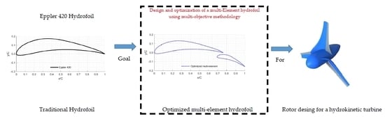
Design and Optimization of a Multi-Element Hydrofoil for a Horizontal-Axis Hydrokinetic Turbine


Abstract
1. Introduction
2. Description of the Optimization Problem
3. Multi-Element Hydrofoil Optimization Framework
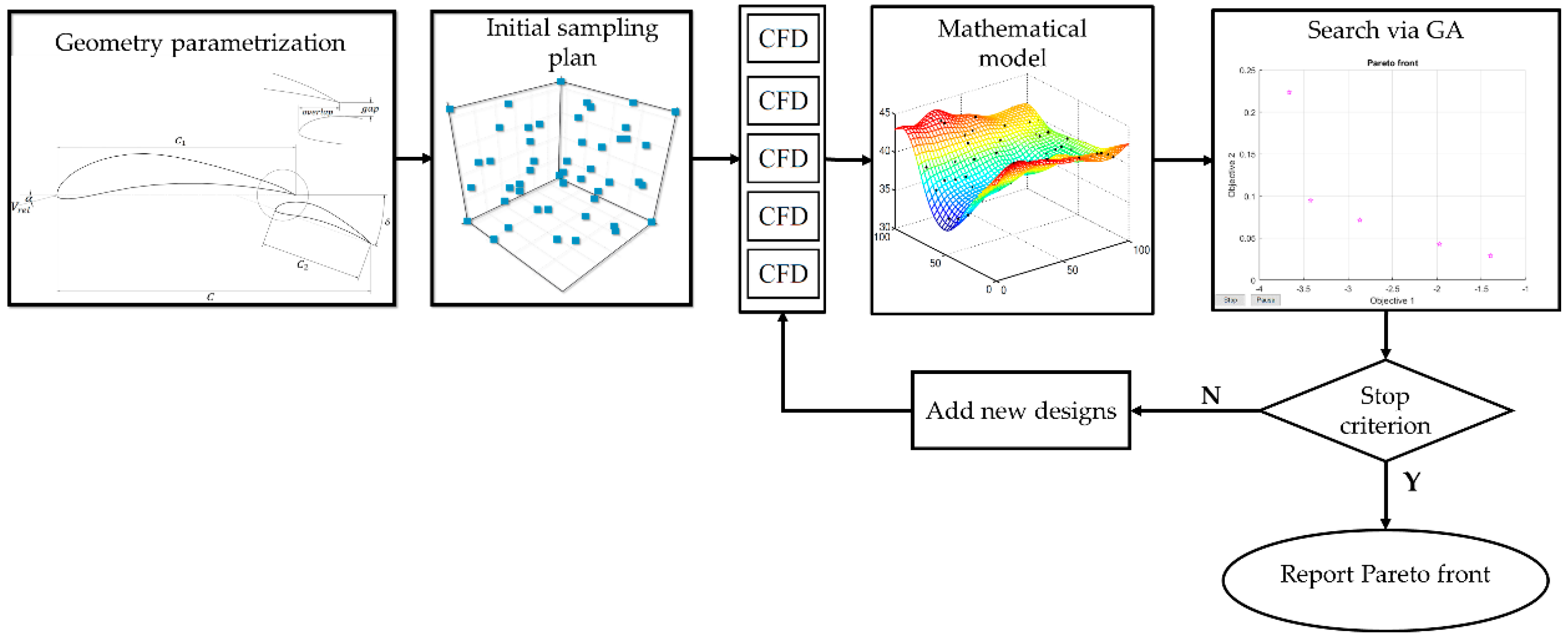
- Initial sampling plan. The substitute model must be first trained using a series of initial simulations, whose evaluation is expensive. These start points are defined by a design of experiment (DoE) technique and should be kept to a minimum. For the current study, a Latin Hypercube Sampling (LHS) was used with 100 points optimized according to the Morris–Mitchell criterion to ensure a uniform distribution of the sample points in the design space [28]. LHS can cover the whole design space to randomly sample and effectively simulate the sample output [55]. The design space is the set of all possible combinations of the design variables that are involved in the multi-element hydrofoil design.
- CFD simulations. For the CFD simulations of the multi-element hydrofoil, was set at 5.517 m/s and α was varied within the previously defined range for the 2D CFD simulation, using Ansys Fluent software (19 R1, Ansys Inc: Canonsburg, PA, UAS, 2009) [40] with the k-ω SST turbulence model. CFD simulations were carried out for the initial sampling plan and for the new design points defined subsequently. The maximum established simulation number was 200. The computational domain used for the CFD had a C-topology, which was meshed with quadrilateral elements. The computational domain stretched 10 chord lengths upstream (radius) and 20 chord lengths downstream. The mesh was built to ensure a y+ ≤ 1, placing at least 30 layers in the boundary layer region. A grid independence study was conducted to ensure the solution convergence, achieving a mesh of about 210,000 elements, considering both efficiency and accuracy. This result was obtained by comparing several different mesh sizes and y+. Five mesh sizes, 94692 (y+ = 0.5846), 131599 (y+ = 0.2929), 203428 (y+ = 0.1431), 349733 (y+ = 0.1426), and 493095 (y+ = 0.0855), were provided. It must be highlighted that the y+ values obtained on the hydrofoil surface were high enough to satisfy the requirements of the k-ω SST turbulence model. The results indicated that CL and CD were basically equal for the meshes 3 and 4. The relative errors on CL and CD were 0.11% and 0.344%, respectively. The results of the convergence study are represented in Figure 4. The mesh 3 was selected in the optimization process.
- 3.
- Mathematical model. In surrogate-based optimization, the surrogate replaces one or more of the objective functions, and the search for the optimum is, therefore, carried out throughout the surrogate model. It must be noted that the surrogate model has to be previously constructed based on a limited, but carefully chosen, number of runs of the original sampling plan function [56]. In the current study, it was decided to use Gaussian processes or Kriging models [28], which take the data of the parameters and the results of the CFD simulations to create a surrogate model. In the design space, the set of non-dominated solutions of the surrogate model lies on a surface, which is commonly known as the Pareto front. Non-dominated solutions are those ones in which superior solutions do not exist within the design space. There are two popular ways of constructing Pareto sets. The first approach combines the optimization criteria into a single objective function; for this purpose, thresholds and penalty functions are often used, as well as weights for linear combinations of the design parameters. The second way for constructing Pareto sets is by using population-based search schemes by means of utilizing algorithms developed for this purpose. In such schemes, a set of designs is worked on concurrently, which evolved toward the final Pareto set in one process. For this, designs are compared to each other and progressed whether they are of high quality and are widely spaced apart from other competing designs. Moreover, an explicit weighting function is not usually required by the referred schemes to combine the objective functions of interest [28,56].
- 4.
- Search. From the surrogate model, new design points are created by using a genetic algorithm (GA). For this propose, the multi-objective GA of the gamultiobj function of the Matlab® software [37] is used. The goal of the algorithm is to find a set of optimal solutions along the Pareto front for a combination of criteria. The initial population size was equal to 20. This number was chosen by multiplying the number of free variables (5 parameters in the current study) by a factor of 4 [36,38]. The total number of generations defined in GA was equal to 100 [34].
- 5.
- Evaluation of new designs. When obtaining the optimal design points of the GA [30,57,58], the three design points of the Pareto front with the highest CL, CD, and CL/CD ratio were evaluated in CFD. This process tends to improve the quality of the surrogate model, and it is useful for reducing a set of candidates prior to further CFD analysis [30,57,58]. For the design point with the best CL/CD ratio, additional CFD studies were carried out by varying α in the integer values close to the given by GA for the referred design point up to a maximum CL/CD ratio of the studied geometry configuration is achieved.
- 6.
- Addition of new design points. Once the results of the CFD simulations of the new design points are obtained, the data are added to the initial sampling to create a new surrogate model and an optimization cycle until the stop criterion is met [28,57]. The purpose of this step is to add points for creating a new surrogate model providing a more optimal objective function.
- 7.
- Stop criterion. During this stage, the same number of new designs points than those ones considered in the initial sampling plan were assessed. Therefore, a total of 200 CFD simulations were considered in order to find the optimal design point that defines the geometric configuration of the multi-element hydrofoil. A proper hydrofoil for the hydrokinetic turbine application must have a high CL/CD ratio for improving the performance, and a high Cpre (lower suction) on the suction side to prevent cavitation. After 200 iterations, the optimized multi-element hydrofoil was defined by the best design point of the last Pareto front (Pareto optimal front) that achieved the optimization requirements (maximum CL and minimum CD), which were subjected to the considered constraints.
4. Results and Discussion
5. Conclusions
Author Contributions
Funding
Acknowledgments
Conflicts of Interest
References
- Dusek, J.E. Leading Edge Vortex Detection Using Bio-Inspired On-Body Pressure Sensing. Ph.D. Thesis, Massachusetts Institute of Technology, Cambridge, MA, USA, 2011. [Google Scholar]
- Sóbester, A.; Forrester, A.I.J. Aircraft Aerodynamic Design: Geometry and Optimization; John Wiley & Sons: Hoboken, NJ, USA, 2014; ISBN 9781118534748. [Google Scholar]
- Aiguabella Macau, R. Formula One Rear Wing Optimization. Available online: https://upcommons.upc.edu/handle/2099.1/12270 (accessed on 5 June 2019).
- Ragheb, A.M.; Selig, M.S. Multielement Airfoils for Wind Turbines. In Wind Energy Engineering; Elsevier: Amsterdam, The Netherlands, 2017; pp. 203–219. ISBN 9780128094518. [Google Scholar]
- Sood, I. Multi-Element Blade Design for MW-Scale Wind Turbines. In Proceedings of the 17th AIAA Aviation Technology, Integration, and Operations Conference, Denver, CO, USA, 5–9 June 2017. [Google Scholar]
- Timmer, W.A.; Rooij, R.P.J.O.M. Summary of the Delft University Wind Turbine Dedicated Airfoils. J. Sol. Energy Eng. 2003, 125, 488–496. [Google Scholar] [CrossRef]
- Van Rooij, R.P.J.O.M.; Timmer, W.A. Roughness Sensitivity Considerations for Thick Rotor Blade Airfoils. J. Sol. Energy Eng. 2003, 125, 468–478. [Google Scholar] [CrossRef]
- Chica, E.; Rubio-Clemente, A. Design of Zero Head Turbines for Power Generation. In Renewable Hydropower Technologies; InTech: London, UK, 2017. [Google Scholar] [CrossRef]
- Nunes, M.M.; Mendes, R.C.F.; Oliveira, T.F.; Brasil Junior, A.C.P. An experimental study on the diffuser-enhanced propeller hydrokinetic turbines. Renew. Energy 2019, 133, 840–848. [Google Scholar] [CrossRef]
- Niebuhr, C.M.; van Dijk, M.; Neary, V.S.; Bhagwan, J.N. A review of hydrokinetic turbines and enhancement techniques for canal installations: Technology, applicability and potential. Renew. Sustain. Energy Rev. 2019, 113, 109240. [Google Scholar] [CrossRef]
- Wang, W.Q.; Yin, R.; Yan, Y. Design and prediction hydrodynamic performance of horizontal axis micro-hydrokinetic river turbine. Renew. Energy 2019, 133, 91–102. [Google Scholar] [CrossRef]
- Kumar, D.; Sarkar, S. A review on the technology, performance, design optimization, reliability, techno-economics and environmental impacts of hydrokinetic energy conversion systems. Renew. Sustain. Energy Rev. 2016, 58, 796–813. [Google Scholar] [CrossRef]
- Jenne, D.S.; Yu, Y.H.; Neary, V. Levelized Cost of Energy Analysis of Marine and Hydrokinetic Reference Models (No. NREL/CP-5000-64013); National Renewable Energy Lab. (NREL): Golden, CO, USA, 2015. [Google Scholar]
- Neary, V.S.; Lawson, M.; Previsic, M.; Copping, A.; Hallett, K.C.; LaBonte, A.; Murray, D. Methodology for Design and Economic Analysis of Marine Energy Conversion (MEC) Technologies (No. SAND2014-3561C); Sandia National Lab. (SNL-NM): Albuquerque, NM, USA, 2014. [Google Scholar]
- Kang, S.; Yang, X.; Sotiropoulos, F. On the onset of wake meandering for an axial flow turbine in a turbulent open channel flow. J. Fluid Mech. 2014, 744, 376–403. [Google Scholar] [CrossRef]
- Kang, S.; Borazjani, I.; Colby, J.A.; Sotiropoulos, F. Numerical simulation of 3D flow past a real-life marine hydrokinetic turbine. Adv. Water Resour. 2012, 39, 33–43. [Google Scholar] [CrossRef]
- Haas, K.A.; Muscalus, A.C. Marine Hydrokinetic Energy: Tidal Streams. In Advances in Coastal Hydraulics; World Scientific Publishing Company: Singapore, 2018; pp. 457–491. [Google Scholar]
- Hill, C.; Musa, M.; Guala, M. Interaction between instream axial flow hydrokinetic turbines and uni-directional flow bedforms. Renew. Energy 2016, 86, 409–421. [Google Scholar] [CrossRef]
- Gotelli, C.; Musa, M.; Guala, M.; Escauriaza, C. Experimental and Numerical Investigation of Wake Interactions of Marine Hydrokinetic Turbines. Energies 2019, 12, 3188. [Google Scholar] [CrossRef]
- Musa, M.; Hill, C.; Sotiropoulos, F.; Guala, M. Performance and resilience of hydrokinetic turbine arrays under large migrating fluvial bedforms. Nat. Energy 2019, 3, 839. [Google Scholar] [CrossRef]
- Yavuz, T.; Koç, E. Performance analysis of double blade airfoil for hydrokinetic turbine applications. Energy Convers. Manag. 2012, 63, 95–100. [Google Scholar] [CrossRef]
- Narsipur, S.; Pomeroy, B.; Selig, M. CFD Analysis of Multielement Airfoils for Wind Turbines. In Proceedings of the 30th AIAA Applied Aerodynamics Conference, New Orleans, LA, USA, 25–28 June 2012. [Google Scholar]
- Zahle, F.; Gaunaa, M.; Sørensen, N.N.; Bak, C. Design and wind tunnel testing of a thick, multi-element high-lift airfoil. In Proceedings of the European Wind Energy Conference and Exhibition 2012, EWEC 2012, Copenhagen, Denmark, 16–19 April 2012. [Google Scholar]
- Ragheb, A.; Selig, M. Multi-Element Airfoil Configurations for Wind Turbines. In Proceedings of the 29th AIAA Applied Aerodynamics Conference, Honolulu, HI, USA, 27–30 June 2011. [Google Scholar]
- Caughey, D.A.; Hafez, M.M. Frontiers of Computational Fluid Dynamics 2006; World Scientific Publishing Co Pte Ltd.: Singapore, 2005; ISBN 9789812703187. [Google Scholar]
- Yondo, R.; Andrés, E.; Valero, E. A review on design of experiments and surrogate models in aircraft real-time and many-query aerodynamic analyses. Prog. Aerosp. Sci. 2018, 96, 23–61. [Google Scholar] [CrossRef]
- Han, Z.; Zhang, K.; Song, W.; Liu, J. Surrogate-based Aerodynamic Shape Optimization with Application to Wind Turbine Airfoils. In Proceedings of the 51st AIAA Aerospace Sciences Meeting including the New Horizons Forum and Aerospace Exposition, Grapevine, TX, USA, 7–10 January 2013. [Google Scholar]
- Forrester, A.I.J. Engineering Design via Surrogate Modelling: A Practical Guide—Constructing a Surrogate; Wiley: Hoboken, NJ, USA, 2008; ISBN 9780470770801. [Google Scholar]
- Demange, J.; Savill, A.M.; Kipouros, T. A Multifidelity Multiobjective Optimization Framework for High-Lift Airfoils. In Proceedings of the 17th AIAA/ISSMO Multidisciplinary Analysis and Optimization Conference, Washington, DC, USA, 13–17 June 2016. [Google Scholar]
- Jo, Y.; Yi, S.; Choi, S.; Lee, D.-J.; Choi, D.-Z. Adaptive Variable-Fidelity Analysis and Design Using Dynamic Fidelity Indicators. AIAA J. 2016, 54, 3564–3579. [Google Scholar] [CrossRef]
- Demange, J.; Savill, A.M.; Kipouros, T. Multifidelity Optimization for High-Lift Airfoils. In Proceedings of the 54th AIAA Aerospace Sciences Meeting, San Diego, CA, USA, 4–8 January 2016. [Google Scholar]
- Kontogiannis, S.G.; Demange, J.; Kipouros, T.; Savill, A.M. A comparison study of two multifidelity methods for aerodynamic optimization. In Proceedings of the 2018 AIAA/ASCE/AHS/ASC Structures, Structural Dynamics, and Materials Conference, Kissimmee, FL, USA, 8–12 January 2018. [Google Scholar]
- Kanazaki, M.; Tanaka, K.; Jeong, S.; Yamamoto, K. Multi-Objective Aerodynamic Exploration of Elements’ Setting for High-Lift Airfoil Using Kriging Model. J. Aircr. 2007, 44, 858–864. [Google Scholar] [CrossRef]
- Jeong, S.; Murayama, M.; Yamamoto, K. Efficient Optimization Design Method Using Kriging Model. J. Aircr. 2005, 42, 1375. [Google Scholar] [CrossRef]
- Li, D. Multi-Objective Design Optimization for High-Lift Aircraft Configurations Supported by Surrogate Modeling. Master’s Thesis, Cranfield University, Cranfield, UK, 2013. [Google Scholar]
- Benini, E.; Ponza, R.; Massaro, A. High-Lift Multi-Element Airfoil Shape and Setting Optimization Using Multi-Objective Evolutionary Algorithms. J. Aircr. 2011, 48, 683–696. [Google Scholar] [CrossRef]
- MATLAB R2019a; MathWorks Inc: Natick, MA, USA, 2019.
- Deb, K. Multi-Objective Optimization Using Evolutionary Algorithms; John Wiley & Sons: Hoboken, NJ, USA, 2008; ISBN 9780470743614. [Google Scholar]
- Yavuz, T.; Koç, E.; Kilkiş, B.; Erol, T.; Balas, C.; Aydemir, T. Performance analysis of the airfoil-slat arrangements for hydro and wind turbine applications. Renew. Energy 2015, 74, 414–421. [Google Scholar] [CrossRef]
- Chica, E.; Perez, F.; Rubio-Clemente, A.; Agudelo, S. Design of a hydrokinetic turbine. WIT Trans. Ecol. Environ. 2015, 195, 137–148. [Google Scholar]
- Xu, L.; Baglietto, E.; Brizzolara, S. Extending the applicability of RANS turbulence closures to the simulation of transitional flow around hydrofoils at low Reynolds number. Ocean Eng. 2018, 164, 1–12. [Google Scholar] [CrossRef]
- Dajani, S.; Shehadeh, M.; Saqr, K.M.; Elbatran, A.H.; Hart, N.; Soliman, A.; Cheshire, D. Numerical Study for a Marine Current Turbine Blade Performance under Varying Angle of Attack. Energy Procedia 2017, 119, 898–909. [Google Scholar] [CrossRef]
- Soulat, L.; Fosso Pouangué, A.; Moreau, S. A high-order sensitivity method for multi-element high-lift device optimization. Comput. Fluids 2016, 124, 105–116. [Google Scholar] [CrossRef]
- Carlton, J.S. Marine Propellers and Propulsion; Elsevier: Amsterdam, The Netherlands, 2012; ISBN 9780080971247. [Google Scholar]
- Molland, A.F.; Bahaj, A.S.; Chaplin, J.R.; Batten, W.M.J. Measurements and predictions of forces, pressures and cavitation on 2-D sections suitable for marine current turbines. Proc. Inst. Mech. Eng. Part M J. Eng. Marit. Environ. 2004, 218, 127–138. [Google Scholar] [CrossRef]
- Chica, E.; Aguilar, J.; Rubio Clemente, A. Analysis of a lift augmented hydrofoil for hydrokinetic turbines. Renew. Energy Power Qual. J. 2019, 17, 49–55. [Google Scholar] [CrossRef]
- Coiro, D.P.; Maisto, U.; Scherillo, F.; Melone, S.; Grasso, F. Horizontal Axis Tidal Current Turbine: Numerical and Experimental Investigations. In Proceedings of the Owemes, Civitavecchia, Italy, 20–22 April 2006. [Google Scholar]
- ANSYS FLUENT. ANSYS Fluent 19 R1 User’s Guide; Ansys Inc: Canonsburg, PA, UAS, 2009. [Google Scholar]
- Menter, F.R. Two-equation eddy-viscosity turbulence models for engineering applications. AIAA J. 1994, 32, 1598. [Google Scholar] [CrossRef]
- Schleicher, W.C.; Riglin, J.D.; Oztekin, A. Numerical characterization of a preliminary portable micro-hydrokinetic turbine rotor design. Renew. Energy 2015, 76, 237–241. [Google Scholar] [CrossRef]
- Silva, P.A.S.F.; De Oliveira, T.F.; Brasil Junior, A.C.P.; Vaz, J.R.P. Numerical study of wake characteristics in a horizontal-axis hydrokinetic turbine. An. Acad. Bras. Cienc. 2016, 88, 1678–2690. [Google Scholar] [CrossRef]
- Gorle, J.M.R.; Chatellier, L.; Pons, F.; Ba, M. Flow and performance analysis of H-Darrieus hydroturbine in a confined flow: A computational and experimental study. J. Fluids Struct. 2016, 66, 382–402. [Google Scholar] [CrossRef]
- Wang, X.; Song, B.; Wang, P.; Sun, C. Hydrofoil optimization of underwater glider using Free-Form Deformation and surrogate-based optimization. Int. J. Nav. Archit. Ocean Eng. 2018, 10, 730–740. [Google Scholar] [CrossRef]
- Ribeiro, A.F.P.; Awruch, A.M.; Gomes, H.M. An airfoil optimization technique for wind turbines. Appl. Math. Model. 2012, 36, 4898–4907. [Google Scholar] [CrossRef]
- Ding, X.; Peng, M.; Shen, M.; Zhu, L.; Che, H.; Zhou, S.; Li, G.; Liu, R. Wind Power Forecasting Based on Extended Latin Hypercube Sampling; Atlantis Press: Paris, France, 2016. [Google Scholar]
- Bernardini, E.; Spence, S.M.J.; Wei, D.; Kareem, A. Aerodynamic shape optimization of civil structures: A CFD-enabled Kriging-based approach. J. Wind Eng. Ind. Aerodyn. 2015, 144, 154–164. [Google Scholar] [CrossRef]
- Arias-Montano, A.; Coello Coello, C.A.; Mezura-Montes, E. Multi-objective airfoil shape optimization using a multiple-surrogate approach. In Proceedings of the 2012 IEEE Congress on Evolutionary Computation, Brisbane, Australia, 10–15 June 2012; pp. 1–8. [Google Scholar]
- Trapani, G. The Design of High Lift Aircraft Configurations through Multi-Objective Optimisation. Ph.D. Thesis, Cranfield University, Cranfield, UK, 2014. [Google Scholar]
- IHS ESDU. ESDU 94026: Introduction to the Estimation of the Lift Coefficients at Zero Angle of Attack and at Maximum Lift for Aerofoils with High-Lift Devices at Low Speeds; IHS ESDU: London, UK, 2000; ISBN 978-0-85679-913-6. [Google Scholar]
- Coello, C.A.; Lamont, G.B.; Van Veldhuisen, D.A. Evolutionary Algorithms for Solving Multi-Objective Problems; Springer: Berlin, Germany, 2007; ISBN 9780387332543. [Google Scholar]
- Zitzler, E.; Thiele, L. Multiobjective evolutionary algorithms: A comparative case study and the strength Pareto approach. IEEE Trans. Evol. Comput. 1999, 3, 257–271. [Google Scholar] [CrossRef]
- Auger, A.; Bader, J.; Brockhoff, D.; Zitzler, E. Theory of the hypervolume indicator: Optimal μ-distributions and the choice of the reference point. In Proceedings of the 10th ACM SIGEVO Workshop on Foundations of Genetic Algorithms, FOGA’09, Orlando, FL, USA, 9–11 January 2009. [Google Scholar]
- Zitzler, E.; Thiele, L.; Laumanns, M.; Fonseca, C.M.; da Fonseca, V.G. Performance assessment of multiobjective optimizers: An analysis and review. IEEE Trans. Evol. Comput. 2003, 7, 117–132. [Google Scholar] [CrossRef]
- Wilcoxon, F. Individual Comparisons by Ranking Methods. Biom. Bull. 1945, 1, 80. [Google Scholar] [CrossRef]


| Airfoil | Developed by | Maximum Thickness (*) | Location of the Maximum Thickness (*) | Maximum Chamber (*) | Location of the Maximum Chamber (*) |
|---|---|---|---|---|---|
| S822 | NREL | 16% | 39.2% | 1.8% | 59.5% |
| S805 | 13.5% | 40% | 2.1% | 35% | |
| CH 10-48-13 | Chuck Hollinger | 12.8% | 30.6% | 10.2% | 49.3% |
| E420 | Richard Eppler | 14.3% | 22.8% | 10.6% | 40.5% |
| E421 | 14.5% | 26% | 8.6% | 37.4% | |
| E422 | 14% | 24.1% | 7.1% | 34.8% | |
| E423 | 12.5% | 23.7% | 9.5% | 41.4% | |
| E857 | 20.3% | 31.5% | 4.9% | 45.1% | |
| Wortmann FX 74-CL5-140 | F.X. Wortmann | 14% | 30.9% | 9.9% | 37.1% |
| Wortmann FX 74-CL5-140 MOD | 13.1% | 27.1% | 9.7% | 41.6% | |
| LA203A | Douglas/Liebeck | 15.7% | 34.3% | 5.5% | 46% |
| S1210 | Selig | 12% | 21.4% | 6.7% | 51.1% |
| S1223 | 12.1% | 19.8% | 8.4% | 49% | |
| UI-1720 | University of Illinois | 13.8% | 19% | 4.6% | 21.2% |
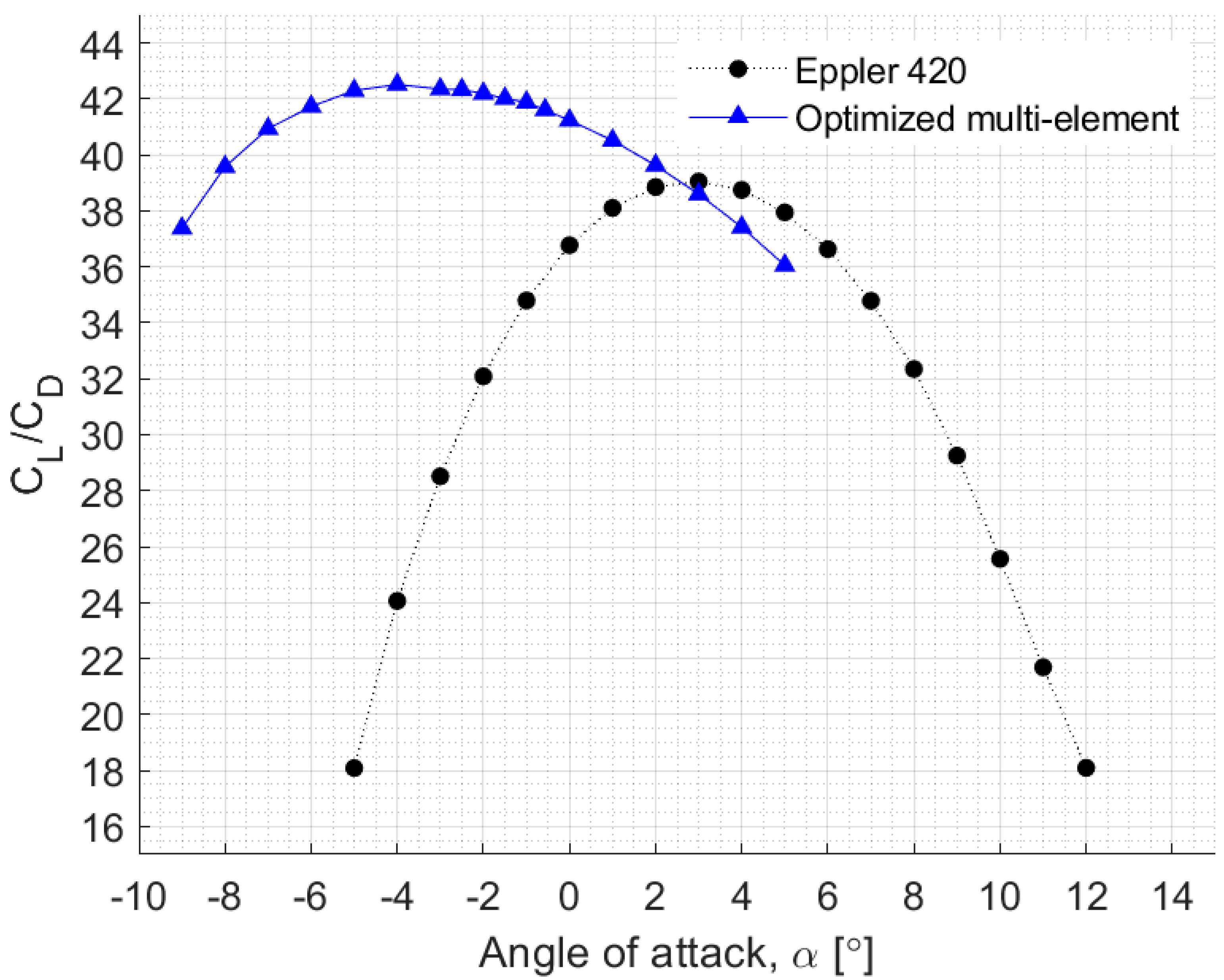
| Parameter | Selected Multi-Element Hydrofoil | Eppler 420 Hydrofoil |
|---|---|---|
| CL | 2.016 | 1.425 |
| CD | 0.047 | 0.036 |
| CL/CD | 42.517 | 39.050 |
| |min Cpre| | 2.248 | 1.786 |
| α | –4° | 3° |
© 2019 by the authors. Licensee MDPI, Basel, Switzerland. This article is an open access article distributed under the terms and conditions of the Creative Commons Attribution (CC BY) license (http://creativecommons.org/licenses/by/4.0/).
Share and Cite
Aguilar, J.; Rubio-Clemente, A.; Velasquez, L.; Chica, E. Design and Optimization of a Multi-Element Hydrofoil for a Horizontal-Axis Hydrokinetic Turbine. Energies 2019, 12, 4679. https://doi.org/10.3390/en12244679
Aguilar J, Rubio-Clemente A, Velasquez L, Chica E. Design and Optimization of a Multi-Element Hydrofoil for a Horizontal-Axis Hydrokinetic Turbine. Energies. 2019; 12(24):4679. https://doi.org/10.3390/en12244679
Chicago/Turabian StyleAguilar, Jonathan, Ainhoa Rubio-Clemente, Laura Velasquez, and Edwin Chica. 2019. "Design and Optimization of a Multi-Element Hydrofoil for a Horizontal-Axis Hydrokinetic Turbine" Energies 12, no. 24: 4679. https://doi.org/10.3390/en12244679
APA StyleAguilar, J., Rubio-Clemente, A., Velasquez, L., & Chica, E. (2019). Design and Optimization of a Multi-Element Hydrofoil for a Horizontal-Axis Hydrokinetic Turbine. Energies, 12(24), 4679. https://doi.org/10.3390/en12244679