1. Introduction
With the gradual depletion of shallow coal resources, the exploitation of resources extends from shallow to deep resources, where the properties of the rocks change substantially. Under the conditions of high ground stress and mining disturbance, mining-induced strata breakage is more severe and the structural characteristics of KS differ substantially from those in shallow mining [
1,
2,
3,
4,
5]. At the same time, under the abutment pressure, a series of disasters are encountered on retreated entry and auxiliary entry, such as rib spalling, roof collapse, and coal bump [
6,
7,
8,
9].
The key strategy for solving these problems is to study the structural characteristics of overburden strata and their influence on the strata behavior. Qian (2003) [
10] put forward the ‘Key Strata Theory’ for the control of strata. Based on this theory, the key stratum (KS) is defined for controlling the whole or partial overburden strata. The primary key stratum (PKS) is defined when the whole or part of the overburden strata above the KS subsides simultaneously with the KS breaking, which is the difference from sub-key stratum (SKS). This study was conducted based on this theory as well. At present, researchers have conducted many studies on these problems [
11,
12,
13,
14,
15,
16,
17,
18,
19]. Based on field monitoring and analytical study, three types of structural models have been found and defined by Ju and Xu [
11]. In addition, a method was put forward for calculating the working resistance for 7.0 m height chocks. According to Kuang et al. [
12], it is very important to establish the time–space correspondence between the movement of the KS and the abutment pressure behaviors. However, most of these studies were conducted in shallow strata and were incomplete in terms of the investigation of the lateral structural characteristics, the movement of the key strata, and its impact on the barrier pillar and auxiliary entry.
At the same time, it is necessary to implement a series of pressure relief measures for controlling the structures of key strata and improving the stability of entry. The pressure relief measures refer to releasing and reducing the pressure on the retreated and auxiliary entries in advance. Traditional measures include hydraulic fracturing technology [
19,
20], holes drilling, destress blasting [
21], and leaving unloading coal pillars [
22], which can release and transfer high stress and alleviate the dynamic pressure phenomenon, but entails extensive engineering work and high costs. In addition, the extension and expansion directions of the fracturing crack cannot be effectively controlled, the position of the final stress lacks theoretical support, and the final pressure relief performance needs to be further verified in engineering applications. Therefore, these pressure relief technologies have not been promoted or widely applied.
Roadway stability is important for safe mining [
23,
24,
25]. He et al. (2017) [
26] proposed a technology of directional blasting fracturing to improve roadway stability. The device and mechanism of directional blasting fracturing is illustrated in
Figure 1. In addition, some researchers have done lots of work on the application of this technology [
27,
28,
29]. While considering the characteristics of low rock tensile strength, He’s team developed an energy gathering pipe device for using directional blasting to produce crack propagation. Field application results (
Figure 2) demonstrate that the technology of directional blasting fracturing can achieve crack propagation in a specified direction without destroying the roof. The process of directional blasting roof fracturing is shown in
Figure 3. The design of the roof fracturing height can increase the height of the immediate roof by using this technology. At the same time, the energy of the explosive blasting and the pressure that is induced by mining can be fully utilized for the fracturing and bulk filling of the immediate roof, thereby ultimately improving the filling percentage in the gob. The movements of key strata are controlled by providing the deformation space, which can effectively limit the rotation space of the KS and reduce the abutment pressure on the retreated and auxiliary entries as well as the disturbance time of the dynamic pressure. The technology of directional blasting fracturing uses the pressure and the bulking factor of the roof above the gob to effectively fill mined-out regions and final pressure relief effect has been verified by a large number of projects. This study was conducted based on this technology.
2. Geological Conditions
The Hongqinghe coal mine is located in the Inner Mongolia province of China, and was the location used for this experiment. Its designed production capacity is 15 Mt/a and the mine field covers 140.7598 km
2. The LW 3
−1101 was 3212 m long and 245 m wide, the coal thickness was 6.2 m, and the dip was 1–7°. The depths of the coal varied from 680 m to 710 m. A 30-m barrier pillar was left to protect auxiliary entry. The occurrence and height of overburden strata varied during mining. The physico-mechanical properties of the overburden strata are shown in
Table 1. By using the KS analytical system [
30], the position of KS of the stratigraphic column was obtained from B3-4 boreholes, as shown in
Figure 4.
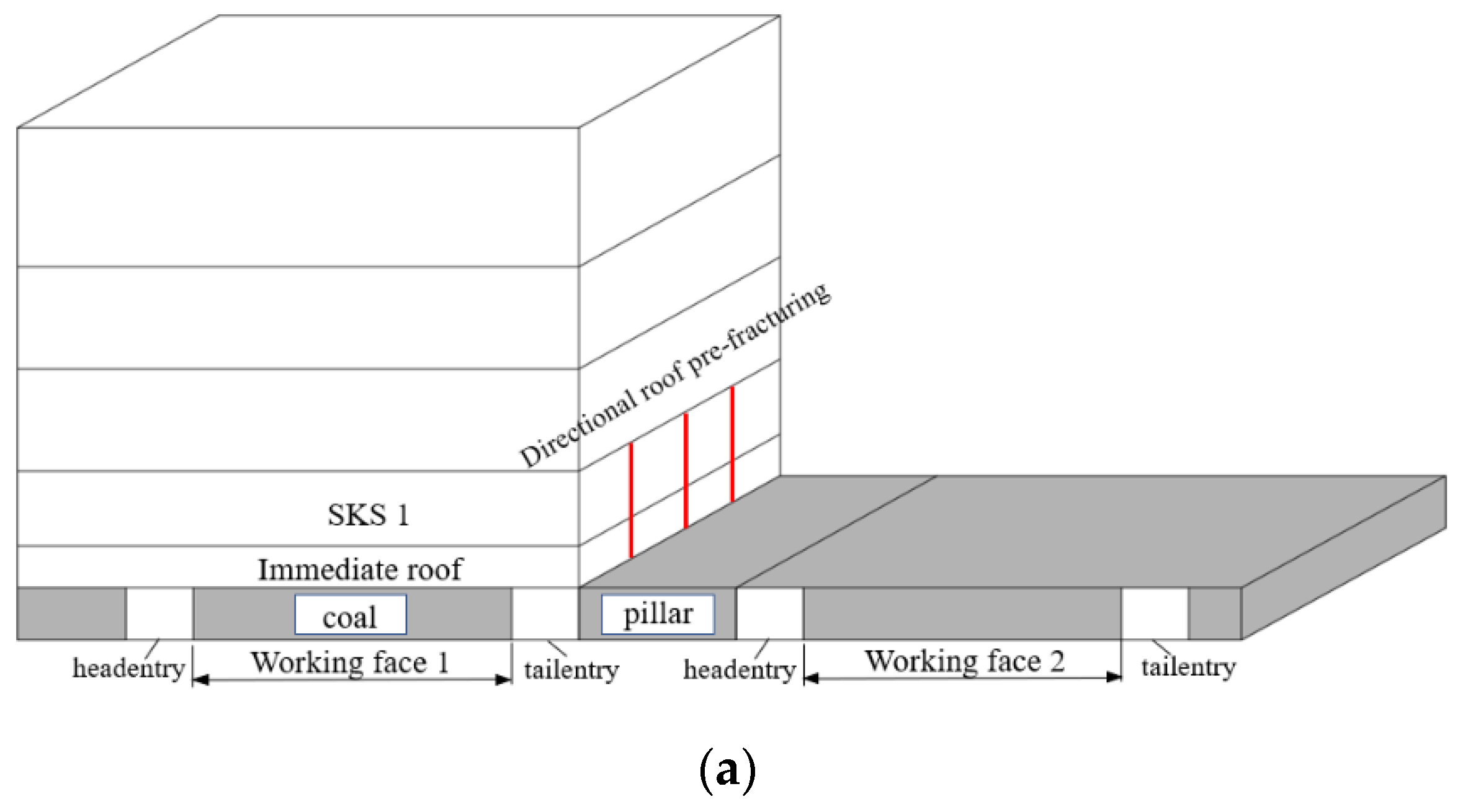
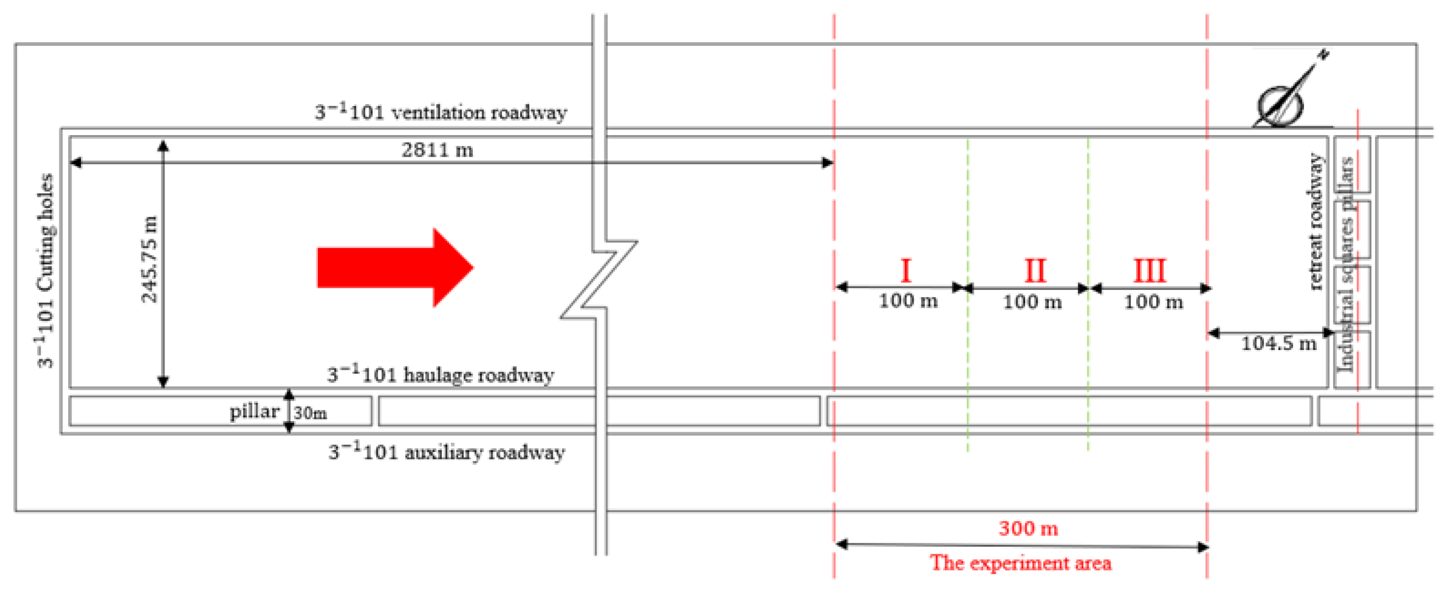
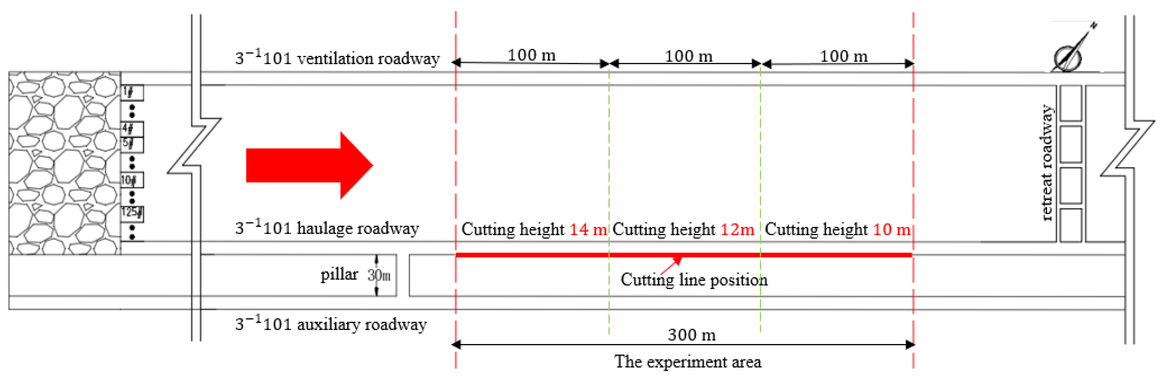
The field experiment area is located in the haulage entry, which ranged from 2811 m to 3111 m, for a total of 300 m, as shown in
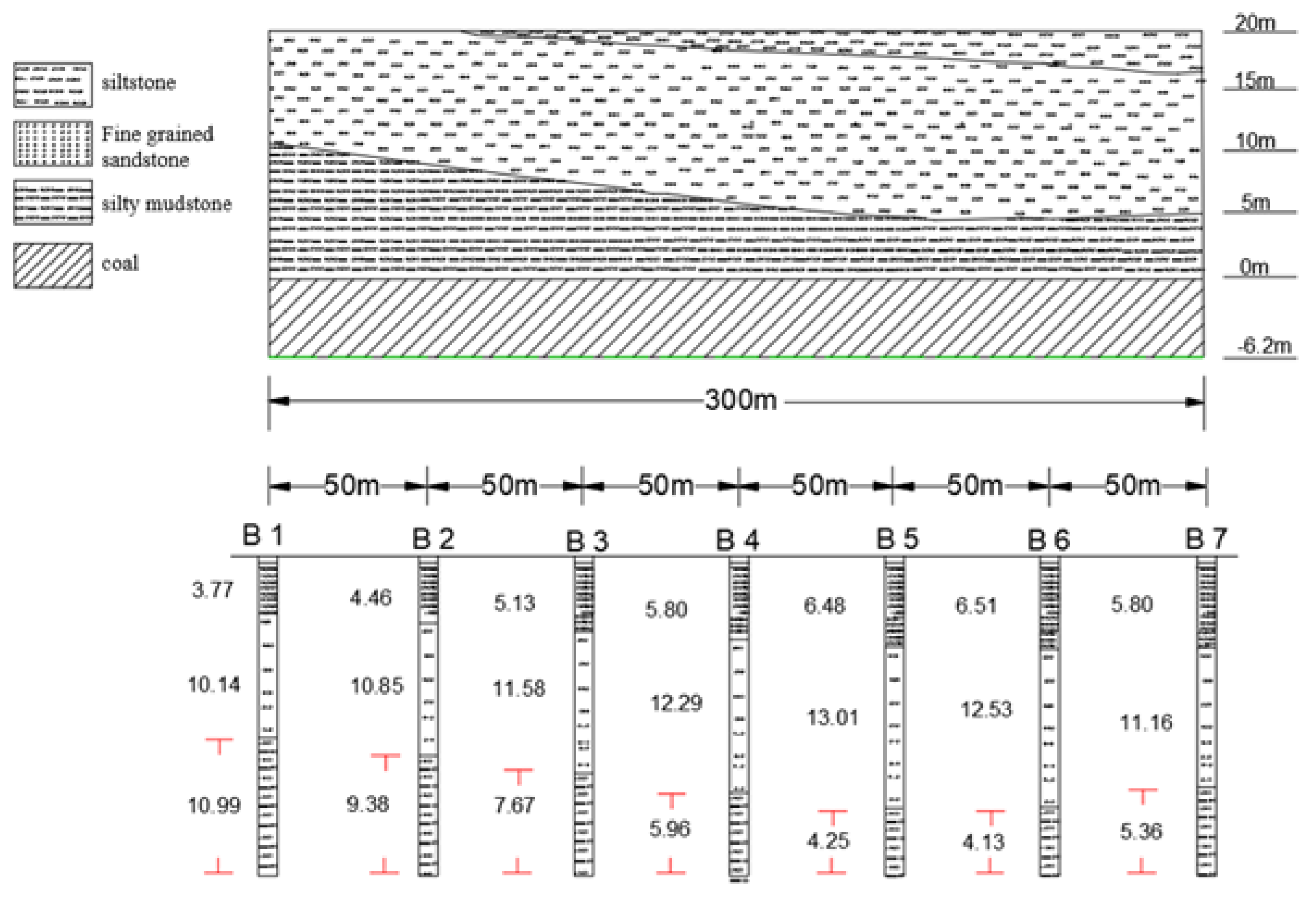
Figure 5. Borehole 7 was 104.5 m from the end-up line. The lithology analysis of the roof was conducted at an interval of 50 m and the variable trend of the roof lithology profile view in the experiment area is shown in
Figure 6. It was observed that the height of KS 1 in the experiment area had little variation, which ranged from 10.14 m to 13.01 m. However, the height of the immediate roof varied substantially, from 4.13 m to 10.99 m. This was the main factor for determining whether KS 1 can develop a stable voussoir beam structure. Based on this analysis, it can be divided into three areas: areas I, II, and III. Area I ranged from bore 1 to bore 3, where the immediate roof height ranged from 10.99 m to 7.67 m; area II ranged from bore 3 to bore 5, where the immediate roof height ranged from 7.67 m to 4.25 m; and area III ranged from bore 5 to bore 7, where the immediate roof height ranged from 4.25 m to 5.36 m. The average heights of immediate roof in three areas were calculated as 9.35 m, 5.96 m, and 4.58 m, respectively.
3. Theory of Balanced Bulk Filling
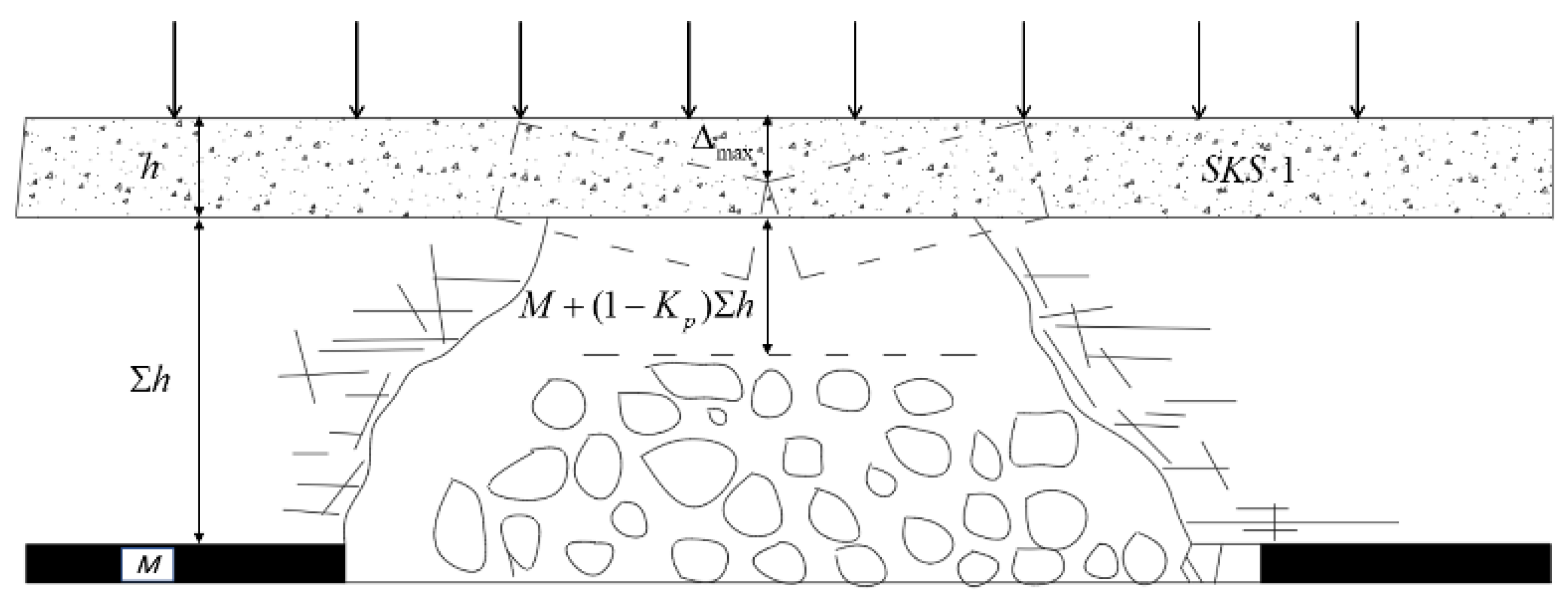
The overburden strata rotates and subsides at the mined-out region during mining.
Figure 7 illustrates the rotation of SKS 1. The distance between the immediate roof and SKS 1 can be expressed as
where Δ is the allowed rotation space of SKS 1,
M is the mining height,
Kp is the bulking coefficient of the immediate roof, and Σ
h is the immediate roof thickness.
When assuming that Δ
max is the maximum rotation of SKS1 needed to develop the stable voussoir beam structure, according to Qian et al. [
5], the following requirement should be satisfied:
Thus, the requirement for forming the voussoir beam structure at the mined-out region is
where
h is the SKS 1 thickness,
l is the broken step of SKS 1,
q is the load of SKS 1 and the overburden strata, and σ
c is the compressive strength of SKS 1.
Thus, the requirement for forming the voussoir beam structure can be effectively satisfied by reducing Δ and increasing Δmax. The rotation Δ can be reduced by increasing Σh and Kp, which can be artificially changed by the technology of directional blasting fracturing, whereas M is a constant that is defined by the geological conditions. The maximum rotation Δmax can be controlled by decreasing h, which can be changed by same technology, whereas q and σc are constants that are defined by the geological conditions.
Accordingly, a model for evaluating the percentage of bulk filling in gob is established and can be expressed as
where
f is the percentage of bulk filling in the gob and
i is the ratio of Σ
h with
M.
According to this equation, the percentage of bulk filling in the gob is related to
Kp and
i. The percentage of bulk filling in the gob is plotted in
Figure 8, which shows that increasing
Kp and
i. can effectively increase the percentage of bulk filling in the gob to stabilize the voussoir beam structure.
According to the percentage of filling in the gob, the filling of the immediate roof can be divided into two types: balanced bulk filling and unbalanced bulk filling:
(1) Balanced bulk filling. The percentage of filling in the gob is 95%–100% and
, where the key strata satisfy the requirements for developing the voussoir beam structure. Based on the theory of balanced bulk filling, the percentage of bulk filling in the gob is related to
Kp and
i, whereas
M is a constant that is defined by the geological conditions. The design of the roof fracturing height (in
Section 5.1) can increase the height of Σ
h to increase
i by using the DBR. At the same time, the energy of the explosive blasting and the pressure that is induced by mining can be fully utilized for the fracturing and collapse of the immediate roof, thereby ultimately improving
Kp and the percentage of filling in the gob. The movements of the key strata are controlled by giving the deformation space, which can effectively limit the rotation space of the key strata and reduce the peak abutment pressure on the retreated and auxiliary entries and the disturbance time of the dynamic pressure.
(2) Unbalanced bulk filling. The percentage of filling in the gob is 0–95% and , where the KS satisfies the requirements for developing the cantilever structure, rather than the stable voussoir beam structure. The deformation space is large in the gob, which cannot limit the rotation space of the KS and increases pressure on the retreated and auxiliary entries as well as the disturbance time of the dynamic pressure.
4. Roof Fracturing Mechanism Based on the Theory of-Balanced Bulk Filling
4.1. Mechanical Model of KS in the Advancing Direction of the Working Face
Based on the theory of-balanced bulk filling, it was concluded that the characteristics of overburden strata are different due to the immediate roof height. In the process of mining the thick coal seam, due to large space of mining and the small thickness of the immediate roof, there are three structures of SKS 1 in the advancing direction of the working face, as illustrated in
Figure 9.
(1) Model A is when an unstable cantilever beam structure can be developed in the SKS 1 due to the small height of immediate roof (
Figure 9a), which cannot meet the balanced bulk filling, while SKS 2 is in a higher strata, which can develop a stable voussoir beam structure. The peak abutment pressure is large and the dynamic disturbance phenomenon is severe under this condition.
(2) Model B is when SKS 1 breaks in advance for the breakage of a higher SKS 2 (
Figure 9b). In this model, the positions of the two KS are relatively close, which would cause periodic alternation between large and short weighting steps. This is particularly the case when occurring for a short weighting step, which shows that the large dynamic disturbance coefficient has a severe impact on the stability of the retreated entry prior to its occurrence.
(3) Model C is when balanced bulk filling is artificially conducted by the technology of directional blasting fracturing (
Figure 9c), which increases Σ
h and
Kp, improves the percentage of bulk filling in the gob, limits the rotation space of the key strata, and ultimately develops the stable voussoir beam structure. This technology can effectively reduce the peak abutment pressure and the dynamic disturbance coefficient, which can improve the stability of retreated entry during mining.
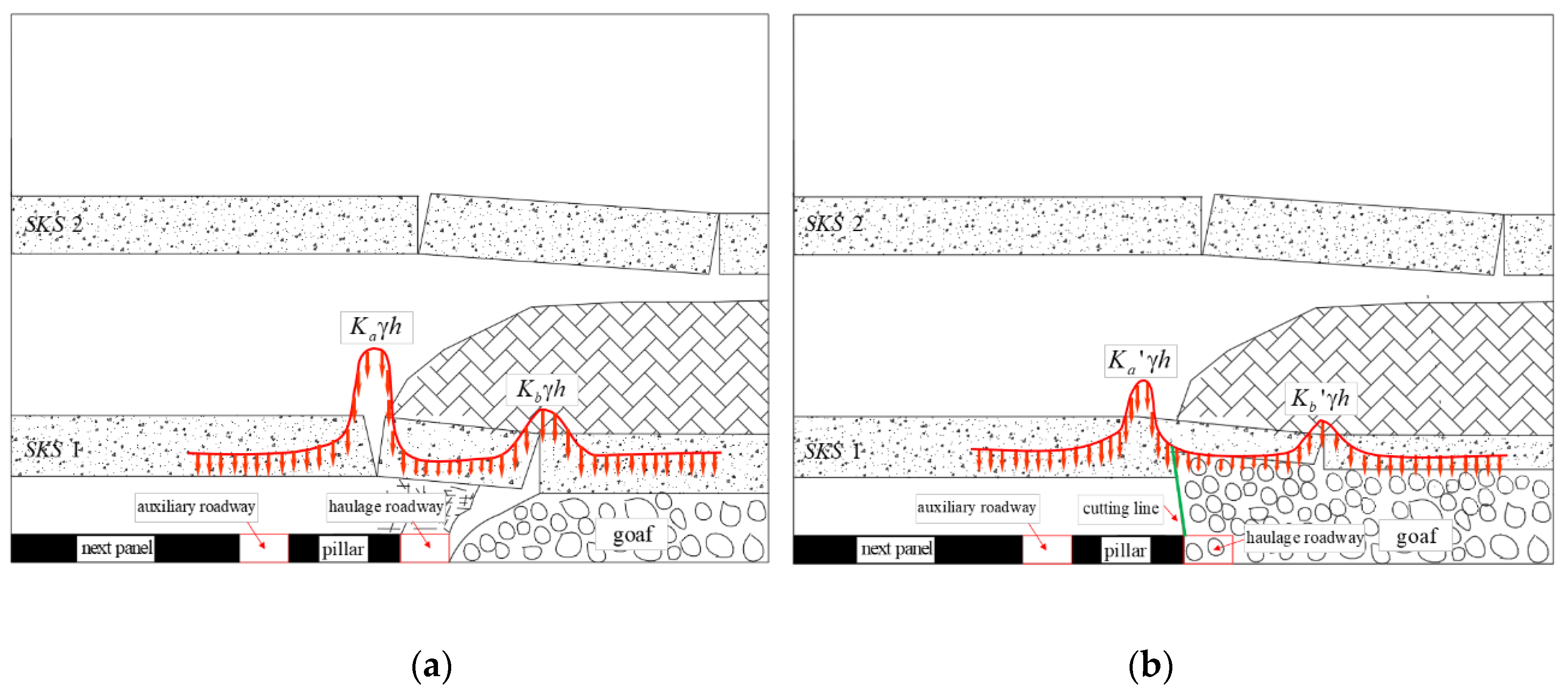
4.2. Mechanical Model of KS in the Lateral Direction of the Working Face
In addition to causing abutment pressure in the advancing direction, lateral abutment pressure is also generated, which causes severe deformation and instability of the auxiliary entry. When deep and thick coalmining is conducted, high peak abutment pressure and a dynamic disturbance coefficient are the main factors that lead to all types of disasters, such as rib spalling, roof collapse, large deformation of the surrounding rock, and coal bump. Based on the above analysis and field observations, there are two structures of SKS 1 in the lateral direction of mining, as illustrated in
Figure 10:
(1) Model D is when the the bulking rock in the gob fails to effectively support the key SKS 1, thereby leading to a large rotation of KS and high peak lateral abutment pressure above the coal pillar and the auxiliary entry (
Figure 10a). Meanwhile, the residual coefficient above the goaf is high, the dynamic disturbance phenomenon is severe and the dynamic disturbance duration is long.
(2) Model E is when using the technology of directional blasting fracturing can effectively cut stress transfer paths into the barrier pillar and the auxiliary entry (
Figure 10b). Thus, the bulking rock in the gob can effectively develop a stable voussoir beam structure, limit the rotation space of KS, reduce high peak stress coefficient above the coal pillar and auxiliary entry and the residual peak stress coefficient above the goaf, and narrow the dynamic disturbance time.
5. Field Test
5.1. Key Parameter DESIGN
5.1.1. Roof Fracturing Height
Based on Equation (3), the characteristics of SKS 1 in three areas were analyzed. Assuming
Kp = 1.3 and the rock density is 25 KN/m
3. For area I, Δ = 3.35 m according to Equation (1). The broken step of SKS 1
l = 15.5 m. The compressive strength of SKS 1 (fine grained sandstone) was 50 MPa and Δ
max = 4.92 m was calculated via Equation (2). Thus, Δ < Δ
max, and a stable voussoir beam structure could be formed in area I. Similarly, calculations were conducted for areas II and III, and both Δ and Δ
max of SKS 1 were calculated and are listed in
Table 2. Based on Equation (3), three roof fracturing heights (14 m, 12 m, and 10 m) were analyzed and are presented in
Table 3, and they satisfy the requirements for developing a stable voussoir beam structure in the experiment area. However, the values of the allowed rotation Δ for the three test areas are 2.15 m, 2.75 m, and 3.35 m, respectively, which can be used to compare the effects of pressure relief under various roof fracturing heights. The location and profile views for the three fracturing heights are illustrated in
Figure 11 and
Figure 12.
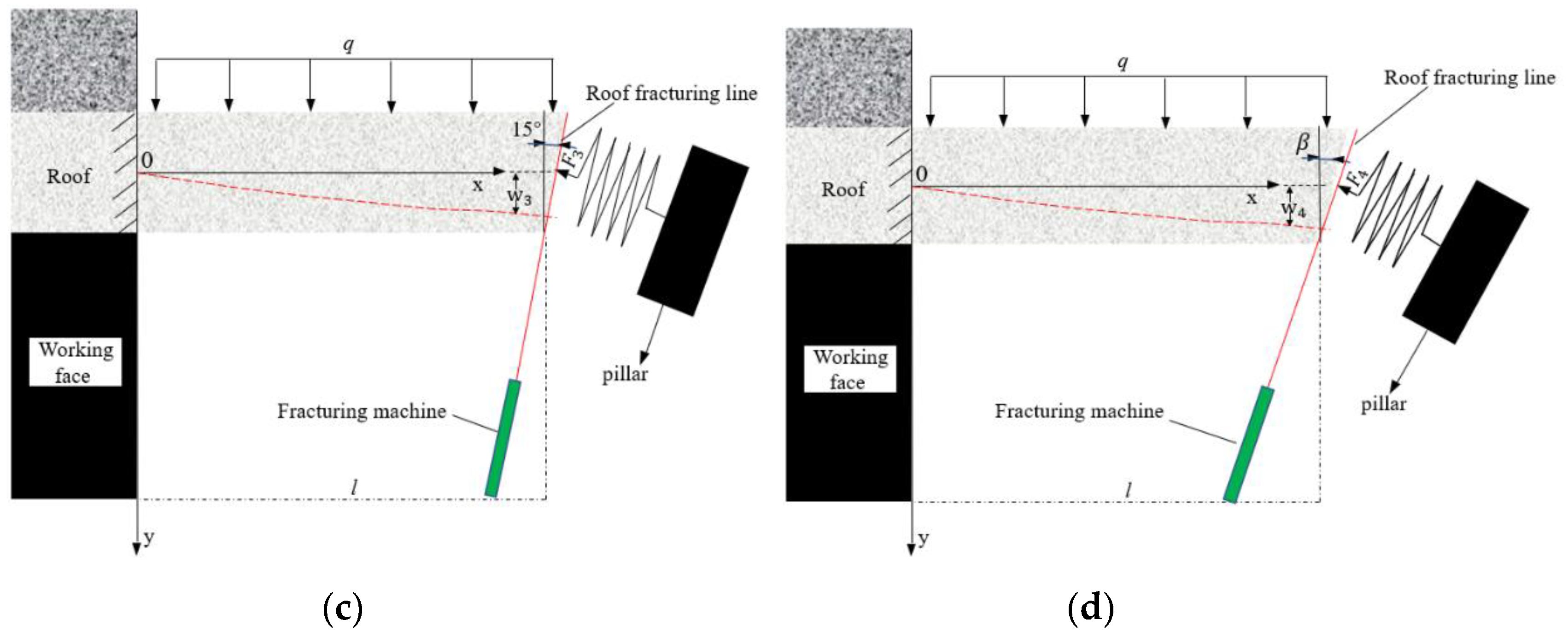
5.1.2. Roof Fracturing Angle
As the longwall face retreated, a reasonable angle was useful for entry roof rotating, subsiding, and bulk filling and could reduce the influence of the lateral abutment pressure on the auxiliary entry. However, the roof fracturing angle must also be considered, as it is beneficial for the stability control of the retreated entry in front of the working face. In
Figure 13a, the pillar roof can generate a downward pressure F
1, thereby leading to advanced abutment pressure coefficient increases and an increased likelihood of entry deformation.
If the fracturing line and the roof is vertical, there is still a normal pressure F
2 between the pillar and the entry (see
Figure 13b). What is more, the propensity support on the entry roof from the pillar may substantially decrease, which may increase the support of the entry roof.
In contrast, if the fracturing direction points toward the pillar roof, it is beneficial for improving the retreated entry stability and reducing the lateral abutment pressure on the barrier pillar and the auxiliary entry. Additionally, it is difficult to construct a fracturing angle when the fracturing degree
β is more than 20° (see
Figure 13d).
Thus, 15° is most reasonable angle (see
Figure 13c).
5.2. Test Process
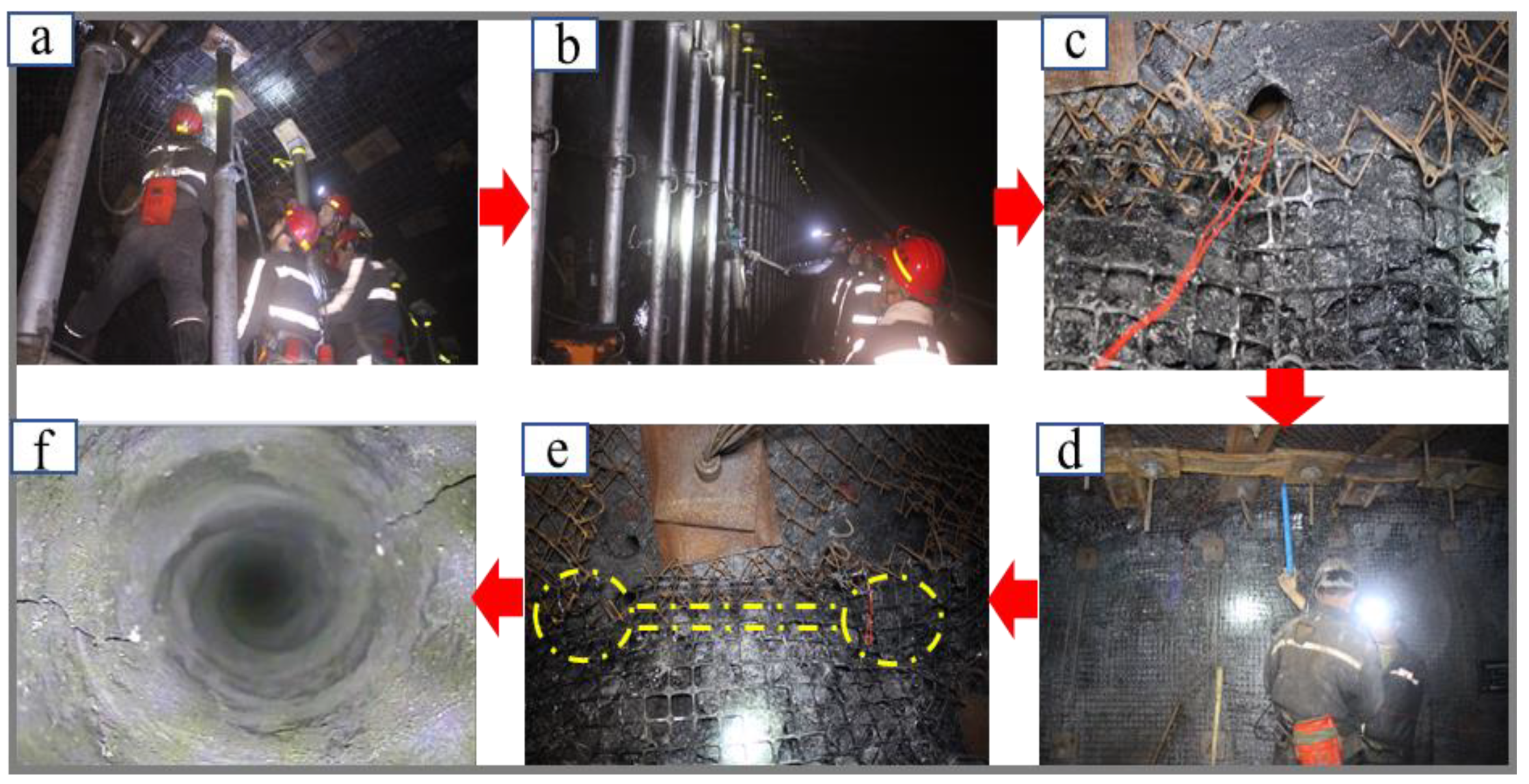
Figure 14 illustrates the technology of directional blasting fracturing in detail over six stages.
StageI: The first step was to adjust the drill stems to a beneficial angle, which is the most fundamental parameter for achieving directional blasting roof fracturing in a specified direction (see
Figure 14a).
StageII: The hole diameter was 42 mm and the depths were 1400 mm, 1200 mm, and 1000 mm, which correspond to experiment areas I, II, and III, respectively. To effectively cut a stress transfer path into the pillar and the auxiliary entry, and to reduce the dynamic effects that are induced by mining, the drilling directions of the holes should be consistent and the distance from the pillar side needed to be 200 mm (see
Figure 14b).
StageIII: Conduct blasting tests. Field tests were necessary for obtaining the rational charge structure and borehole-to-borehole distance, including 400 mm, 500 mm, and 600 mm in case there were some errors in the theoretical calculations (see
Figure 15a). Finally, the 3
−1101 haulage entry adopted an air-space charge with a borehole-to-borehole distance of 500 mm, as shown in
Figure 14c. The charge structure is “3 + 3 + 3 + 3 + 3 + 3 + 2 + 1”, “3 + 3 + 3 + 3 + 3 + 2 + 1” and “3 + 3 + 3 + 2 + 1” patterns, which corresponded to experiment areas I, II and III, respectively, and the stemming length is 3000 mm, as illustrated in
Figure 15.
Stage IV: Energy gathering pipes that were filled with explosives were installed in the holes. The cohesive energy flow was extended by the specified direction (see
Figure 14d).
StageV: Through blasting, the crack propagation at the roof surface penetrated the whole roof (see
Figure 14e).
StageVI: The crack growth rate met the specification (90%), which was determined by analyzing the crack distribution in the holes., according to which the energy-gathering performance of the technology of directional blasting fracturing was determined to be satisfactory (see
Figure 14f).
5.3. Results
To evaluate the effects of directional blasting fracturing on the abutment pressure in the advancing direction and on the lateral abutment pressure in the process of 3
−1101 working face mining in Hongqinghe Coal Mine, three factors were monitored: the advancing abutment pressure, the lateral abutment pressure, and the deformation of the auxiliary entry. The monitoring equipment arrangement is illustrated in
Figure 16.
(1) On the 3−1101 working face, 10 KJ216 stress monitoring apparatuses were installed and labeled 1#-10#, with an interval of 20 m.
(2) The P1-P10 stress station was located in the experiment area with an interval of 30 m. The P11 station was located in the area without a fracturing roof. Each station was equipped with two holes, the horizontal spacing of the holes was 0.5 m, and the drilling depths were 4 m and 8 m. Each hole was 1.5 m away from the bottom plate, and the holes were arranged approximately horizontally. An angle of 3–5° was required so the water in the drilling process could smoothly flow out from the hole, as illustrated in
Figure 17.
(3) The S1–S10 displacement station was located in the experiment area with an interval of 30 m. The S11 station was located in the area without a fracturing roof.
5.3.1. Abutment Pressure Characteristics in the Advancing Direction
To explore the influence of this technology on abutment pressure characteristics in the advancing direction, stress monitoring apparatus 1# was selected for the analysis. The distance from the fracturing line was 8 m. By comparing the pressure characteristics in the experiment areas with the area without fracturing roof, the following conclusions could be drawn (see
Figure 18):
(1) The maximum peak abutment pressure was 37.8 MPa after 14-m-height fracturing and was 8.8 MPa smaller than without the fracturing roof. Meanwhile, the average pressure was reduced by roughly 60% by using the technology of directional blasting fracturing. According to the field monitoring results, this technology could reduce the stress concentration and improve the stability of the retreated entry.
(2) Comparing three roof fracturing heights, namely, 14 m, 12 m, and 10 m, the maximum peak abutment pressure was 37.8 MPa, 40.2 MPa, and 44.4 MPa, respectively. The average abutment pressure was 20.42 MPa, 22.55 MPa, and 24.21 MPa, respectively, therefore, the 14 m height had the best pressure relief performance. Therefore, considering the conditions in the field, the roof fracturing height was higher, the bulk filling percentage of the gob was higher, and the space for the key strata to rotate was smaller, facilitating the development of the voussoir beam structure by using this technology; in addition, the pressure relief effect was superior.
5.3.2. Abutment Pressure Characteristics in the Lateral Direction
The monitoring data came from two holes, whose depths are 4 m and 8 m. Through the analysis of the stress monitoring data in equipment P11, P10, P6, and P4, which correspond to 0 m, 10 m, 12 m and 14 m, the conclusion is as follows:
(1) Pressure characteristics in the 4-m hole: The maximum stress was 19.5 MPa after roof fracturing at a height of 14 m and was 8.7 MPa smaller than without fracturing roof (
Figure 19a). The advanced effect range decreased by 40 m after adopting the technology of directional blasting fracturing. According to the field monitoring results, this technology could effectively reduce the stress condition and could affect the range above the pillar. However, with or without this technology, the shallow confining coal transforms from elastic to plastic due to caving, there is a dramatic drop, the barrier pillar loses its bearing capacity, and the plastic zone begins to gradually break down.
(2) Pressure characteristics in the 8-m hole: Equipment #11 started to increase gradually after it passed 100 m and reached its maximum of 44.6 MPa at 50 m behind the working face (
Figure 19b). Afterwards, a dramatic drop occurred and the pillar lost its bearing capacity. However, the equipment P10, P6, and P4 started to increase gradually when they were advanced by 40–70 m, and reached the maximum at 25–40 m behind the working face. When the coal body was 50–70 m behind the working face, the abutment pressure gradually increased and subsequently stabilized. The internal stress is always high. The coal pillar stress does not exceed the limit of the coal body strength.
(3) Comparing three roof fracturing heights, namely, 14 m, 12 m, and 10 m, the 14-m height had the best pressure relief performance. Therefore, considering the conditions in the field, the roof fracturing height was higher and the coal pillar strength was more stable.
5.3.3. Deformation Behavior of the Auxiliary Entry
Through our analysis of the deformation monitoring data in equipment S11, S10, S6, and S4, which corresponded to 0 m, 10 m, 12 m, and 14 m, the following conclusions were drawn (see
Figure 20):
(1) The deformation process of the two ribs includes three stages: stage I, in which the auxiliary entry is affected by the lateral abutment pressure that is induced by mining, which corresponds to 50 –70m advanced working face, and the deformation increases smoothly; stage II corresponds to the dynamic pressure zone, which is roughly 0–150 m behind the working face, and due to KS rotation, sinking, and periodical weighting, the auxiliary entry is in an unstable state and the deformation increases quickly; stage III corresponds to the stabilization zone, which is approximately 150–200 m behind the working face, and due to bulk filling characteristics, the gob is in a stable state and the deformation is almost stable.
(2) The maximum deformation was 238 mm after roof fracturing at a height of 14 m, which was 200 mm smaller than without roof fracturing. The effect range decreased by 40 m in front of the working face and 50 m behind the working face by using this technology. The field monitoring results demonstrated that this technology could effectively reduce the large deformation condition and effect range, which improves the stability and safety of the auxiliary entry.
(3) Comparing three roof fracturing heights, namely, 14 m, 12 m, and 10 m, the 14-m height exhibited the best deformation control performance. Therefore, when considering the conditions in the field, the roof fracturing height was higher and the deformation of the auxiliary entry was smaller.
6. Conclusions
Traditional methods such as hydraulic fracturing technology, hole drilling, destress blasting, and leaving unloading coal pillars have limited effects on pressure relief due to their obvious drawbacks. Thus, the technology of directional blasting fracturing is put forward for controlling the stability of retreated and auxiliary entry, and the energy gathering pipe device is developed for realizing directional blasting fracturing, thus producing crack propagation. Field application results in Hongqinghe coal mine demonstrate that this technology can realize directional roof presplitting to a designed depth along the roof while not destroying the roof.
This study introduces a new technology, namely, directional blasting fracturing, characterized by installing a gathering tube in the borehole and detonating an explosive to break the roof, which can achieve directional roof fracturing according to the design angle. A theory of balanced bulk filling is established based on the requirements for developing the voussoir beam structure, which can be used to effectively evaluate the percentage of bulk filling in gob and to determine which structure the key strata belongs to. Based the theory of balanced bulk filling, two types of structural models in the advancing and lateral directions of the working face are proposed and defined. Model C can develop a stable voussoir beam structure, limiting the rotation space of the key strata and reducing the peak abutment pressure and the dynamic disturbance time in the advancing direction. Model E is defined as when directional blasting fracturing effectively cuts a stress transfer path into the barrier pillar and auxiliary entry, the peak abutment pressure on the barrier pillar is smaller, and the dynamic disturbance time is short, effectively improving the stability of the auxiliary entry.
Key parameters of the directional blasting fracturing were designed, such as the roof fracturing height, angle and charge structure. The field application performance of this technology at the longwall face of 3−1101 was evaluated by analyzing the whole process of abutment pressure in the advancing and lateral directions of the working face and the surrounding rock deformation of the auxiliary entry.
However, the directional blasting fracturing technology needs many explosives, which poses risks to workers and is hard to purchase under the control of the Chinese Public Security Bureau, so our team are researching a novel explosive substitute, called instantaneous slitter equipment, which has been previously tested in many coal mines. Compared to traditional blasting roof-fracturing, instantaneous slitter equipment has better characteristics, such as being non-explosive, a sealed ignition, short action time, low costs, a high kindling point, high energy provision, and so on.
Author Contributions
Conceptualization, H.X.; methodology, H.X. and X.Z.; validation, H.X., Y.G. and X.T.; formal analysis, X.Z., D.Y. and H.W.; resources, H.X. and Y.G.; writing—original draft preparation, H.X.; writing—review and editing, Y.G.; supervision, Y.G.; project administration, Y.G.; funding acquisition, H.X., X.Z. and Y.G.
Funding
This research was funded by the National Natural Science Foundation of China [grant number 51674265], the State Key Laboratory for Geomechanics and Deep Underground Engineering, China University of Mining & Technology, Beijing (No. SKLGDUEK1928), and China Postdoctoral Science Foundation (grant number 2019M650896), which are gratefully acknowledged.
Conflicts of Interest
The authors declare no conflict of interest.
References
- Sun, J.; Wang, S. Rock mechanics and rock engineering in China: Developments and current state-of-the-art. Int. J. Rock Mech. Min. Sci. 2000, 37, 447–465. [Google Scholar] [CrossRef]
- Xie, H.; Gao, M.; Zhang, R.; Peng, G.; Wang, W.; Li, A. Study on the Mechanical Properties and Mechanical Response of Coal Mining at 1000 m or Deeper. Rock Mech. Rock Eng. 2018, 52, 1475–1490. [Google Scholar] [CrossRef]
- Xie, H.P. Resources development under high ground stress: Present state, base science problems and perspective. Sci. Foreland Future 2002, 6, 179–191. (In Chinese) [Google Scholar]
- He, M.C. Present State and Perspective of Rock Mechanics in Deep Mining Engineering. In Proceedings of the 8th Rock Mechanics and Engineering Conference, Tuscaloosa, Alabam, 23–25 June 1986; Chinese Society of Rock Mechanics and Engineering, Ed.; Science Press: Beijing, China, 2004; pp. 88–94. (In Chinese). [Google Scholar]
- Qian, M.G.; Shi, P.W.; Xu, J.L. Ground Pressure and Strata Control; University of Mining and Technology Press: Xuzhou, China, 2010. (In Chinese) [Google Scholar]
- Saeedi, G.; Shahriar, K.; Rezai, B.; Karpuz, C. Numerical modelling of out-of- seam dilution in longwall retreat mining. Int. J. Rock Mech. Min. Sci. 2010, 47, 533–543. [Google Scholar] [CrossRef]
- Bai, Q.S.; Tu, S.H.; Zhang, X.G.; Zhang, C.; Yuan, Y. Numerical modeling on brittle failure of coal wall in longwall face—A case study. Arab. J. Geosci. 2014, 7, 5067–5080. [Google Scholar] [CrossRef]
- Bai, Q.S.; Tu, S.H.; Chen, M.; Chen, M.; Zhang, C. Numerical modeling of coal wall spall in a longwall face. Int. J. Rock Mech. Min. Sci. 2016, 88, 242–253. [Google Scholar] [CrossRef]
- Li, Z.; Xu, J.; Yu, S.; Ju, J.; Xu, J.; Sciubba, E. Mechanism and prevention of a chock support failure in the longwall top-coal caving faces: A case study in Datong Coalfield, China. Energies 2018, 11, 288. [Google Scholar] [CrossRef] [Green Version]
- Qian, M.G.; Miao, X.X.; Xu, J.L. Study of Key Strata Theory in Ground Control; University of Mining and Technology Press: Xuzhou, China, 2003. (In Chinese) [Google Scholar]
- Ju, J.F.; Xu, J.L. Structural characteristics of key strata and strata behaviour of a fully mechanized longwall face with 7.0 m height chocks. Int. J. Rock Mech. Min. Sci. 2013, 58, 46–54. [Google Scholar] [CrossRef]
- Kuang, T.; Li, Z.; Zhu, W.; Xie, J.; Ju, J.; Liu, J.; Xu, J. The impact of key strata movement on ground pressure behaviour in the Datong coalfield. Int. J. Rock Mech. Min. Sci. 2019, 119, 193–204. [Google Scholar] [CrossRef]
- Li, Z.; Xu, J.; Ju, J.; Zhu, W.; Xu, J. The effects of the rotational speed of voussoir beam structures formed by key strata on the ground pressure of stopes. Int. J. Rock Mech. Min. Sci. 2018, 108, 67–79. [Google Scholar] [CrossRef]
- Liang, Y.; Li, B.; Zou, Q. Movement type of the first subordinate key stratum and its influence on strata behavior in the fully mechanized face with large mining height. Arab. J. Geosci. 2019, 12, 31. [Google Scholar] [CrossRef]
- Huang, B.; Liu, J.; Zhang, Q. The reasonable breaking location of overhanging hard roof for directional hydraulic fracturing to control strong strata behaviors of gob-side entry. Int. J. Rock Mech. Min. Sci. 2018, 103, 1–11. [Google Scholar] [CrossRef]
- Li, J.; Huang, Y.; Zhang, J.; Li, M.; Qiao, M.; Wang, F. The Influences of Key Strata Compound Breakage on the Overlying Strata Movement and Strata Pressure Behavior in Fully Mechanized Caving Mining of Shallow and Extremely Thick Seams: A Case Study. Adv. Civ. Eng. 2019, 2019, 5929635. [Google Scholar] [CrossRef]
- Zhu, W.; Yu, B. Breakage form and its effect on strata behavior of far field key stratum in large space stope. Coal Sci. Technol. 2018, 46, 99–104. [Google Scholar]
- Chen, Y.; Gong, F.G.; Zhao, M. The study on the movement law of overlying strata in fully mechanized caving face under alluvium with huge thickness in deep mine. IOP Conf. Ser. Earth Environ. Sci. 2017, 59, 012039. [Google Scholar] [CrossRef] [Green Version]
- Zha, W.; Hua, X.; Wang, J.; Zheng, H.; Wang, N.; Liu, X. Study on strata movement rules and hydraulic support selection for fully-mechanized working face with large mining height of extra thick coal seam in deep well. J. Saf. Sci. Technol. 2014, 10, 75–80. [Google Scholar]
- He, H.; Dou, L.; Fan, J.; Du, T.; Sun, X. Deep-hole directional fracturing of thick hard roof for rockburst prevention. Tunn. Undergr. Space Technol. 2012, 32, 34–43. [Google Scholar] [CrossRef]
- Konicek, P.; Soucek, K.; Stas, L.; Singh, R. Long-hole destress blasting for rock-burst control during deep underground coal mining. Int. J. Rock Mech. Min. Sci. 2013, 61, 141–153. [Google Scholar] [CrossRef]
- Zhang, G.C.; He, F.L.; Jia, H.G.; Lai, Y.H. Analysis of Gateroad Stability in Relation to Yield Pillar Size: A Case Study. Rock Mech. Rock Eng. 2017, 50, 263–1278. [Google Scholar] [CrossRef]
- Wang, Q.; He, M.; Yang, J.; Gao, H.; Jiang, B.; Yu, H. Study of a no-pillar mining technique with automatically formed gob-side entry retaining for longwall mining in coal mines. Int. J. Rock Mech. Min. Sci. 2018, 110, 1–8. [Google Scholar] [CrossRef]
- Wang, Q.; Gao, H.; Yu, H.; Jiang, B.; Liu, B. Method for Measuring Rock Mass Characteristics and Evaluating the Grouting-Reinforced Effect Based on Digital Drilling. Rock Mech. Rock Eng. 2019, 52, 841–851. [Google Scholar] [CrossRef]
- Wang, Q.; Jiang, B.; Pan, R.; Li, S.; He, M.; Sun, H.; Qin, Q.; Yu, H.; Luan, Y. Failure Mechanism of Surrounding Rock with High Stress and Confined Concrete Support System. Int. J. Rock Mech. Min. Sci. 2018, 102, 89–100. [Google Scholar] [CrossRef]
- He, M.; Gao, Y.; Yang, J.; Guo, Z.; Wang, E.; Wang, Y. The energy-gathered roof cutting technology in non-pillar mining and its impact on stress evolution of surrounding rocks. Chin. J. Rock. Mech. Eng. 2017, 36, 1314–1325. [Google Scholar]
- Zhang, X.; Chen, L.; Gao, Y.; Hu, J.; Yang, J.; He, M. Study of An Innovative Approach of Roof Presplitting for Gob-Side Entry Retaining in Longwall Coal Mining. Energies 2019, 12, 3316. [Google Scholar] [CrossRef] [Green Version]
- Yang, X.; Liu, C.; Ji, Y.; Zhang, X.; Wang, S. Research on roof cutting and pressure releasing technology of directional fracture blasting in dynamic pressure roadway. Geotech. Geol. Eng. 2019, 37, 1555–1567. [Google Scholar] [CrossRef]
- Gao, Y.; Wang, Y.; Yang, J.; Zhang, X.; He, M. Meso-and macroeffects of roof split blasting on the stability of gateroad surroundings in an innovative nonpillar mining method. Tunn. Undergr. Space Technol. 2019, 90, 99–118. [Google Scholar] [CrossRef]
- Xu, J.L.; Qian, M.G. Method to distinguish key strata in overburden. J. China Univ. Min. Technol. 2000, 29, 463–467. (In Chinese) [Google Scholar]
Figure 1.
The device and mechanism of the directional blasting roof fracturing. (a) Device; (b) The mechanism.
Figure 1.
The device and mechanism of the directional blasting roof fracturing. (a) Device; (b) The mechanism.
Figure 2.
Photographs from field applications. (a) Granite; (b) Sandstone.
Figure 2.
Photographs from field applications. (a) Granite; (b) Sandstone.
Figure 3.
Process of directional blasting roof fracturing. (a) Hole drilling; (b) Blasting; (c) Pressure relief.
Figure 3.
Process of directional blasting roof fracturing. (a) Hole drilling; (b) Blasting; (c) Pressure relief.
Figure 4.
Stratigraphic column of the B3-4 borehole.
Figure 4.
Stratigraphic column of the B3-4 borehole.
Figure 5.
Location diagram of the experiment area.
Figure 5.
Location diagram of the experiment area.
Figure 6.
Roof lithology profile view in the experiment area.
Figure 6.
Roof lithology profile view in the experiment area.
Figure 7.
Rotating space of SKS 1.
Figure 7.
Rotating space of SKS 1.
Figure 8.
Relationships between f and Kp and i.
Figure 8.
Relationships between f and Kp and i.
Figure 9.
Key strata (KS) structural models in the advancing direction. (a) Model A; (b) Model B; (c) Model C.
Figure 9.
Key strata (KS) structural models in the advancing direction. (a) Model A; (b) Model B; (c) Model C.
Figure 10.
KS structural models in the lateral direction of the working face. (a) Model D; (b) Model E.
Figure 10.
KS structural models in the lateral direction of the working face. (a) Model D; (b) Model E.
Figure 11.
Locations of three roof fracturing heights.
Figure 11.
Locations of three roof fracturing heights.
Figure 12.
Profile views of three roof fracturing heights. (a) Design I; (b) Design II; (c) Design III.
Figure 12.
Profile views of three roof fracturing heights. (a) Design I; (b) Design II; (c) Design III.
Figure 13.
Roof fracturing direction design: (a) The fracturing direction points to the entry roof; (b) The fracturing direction is perpendicular to the entry roof; (c) The rational fracturing direction for the 3−1101 haulage entry; (d) The fracturing angle is too large.
Figure 13.
Roof fracturing direction design: (a) The fracturing direction points to the entry roof; (b) The fracturing direction is perpendicular to the entry roof; (c) The rational fracturing direction for the 3−1101 haulage entry; (d) The fracturing angle is too large.
Figure 14.
Roof fracturing construction process: (a) Installing drill stems; (b) Drilling holes; (c) Blast testing; (d) Charging process; (e) Crack distribution at the roof surface; (f) Crack distribution in the holes.
Figure 14.
Roof fracturing construction process: (a) Installing drill stems; (b) Drilling holes; (c) Blast testing; (d) Charging process; (e) Crack distribution at the roof surface; (f) Crack distribution in the holes.
Figure 15.
Roof blasting tests and charging parameters. (a) Blasting tests; (b)14 m; (c) 12 m; (d) 10 m.
Figure 15.
Roof blasting tests and charging parameters. (a) Blasting tests; (b)14 m; (c) 12 m; (d) 10 m.
Figure 16.
Monitoring equipment arrangement.
Figure 16.
Monitoring equipment arrangement.
Figure 17.
Profile view of the hole arrangement.
Figure 17.
Profile view of the hole arrangement.
Figure 18.
Comparison of the abutment pressure characteristics in different roof fracturing heights areas.
Figure 18.
Comparison of the abutment pressure characteristics in different roof fracturing heights areas.
Figure 19.
Pressure characteristics of pillars with the distance from the working face. (a) a 4-m stress meter borehole; (b) a 8-m stress meter borehole.
Figure 19.
Pressure characteristics of pillars with the distance from the working face. (a) a 4-m stress meter borehole; (b) a 8-m stress meter borehole.
Figure 20.
Deformation of the auxiliary entry. (a) Deformation of both ribs; (b) Deformation of the top and bottom plates.
Figure 20.
Deformation of the auxiliary entry. (a) Deformation of both ribs; (b) Deformation of the top and bottom plates.
Table 1.
Physico-mechanical properties of the overburden strata in LW3−1101.
Table 1.
Physico-mechanical properties of the overburden strata in LW3−1101.
| No. | Rock Strata | Bulk Density
(KN/m3) | Elastic Modulus
(GPa) | Tensile Strength
(MPa) |
|---|
| 1 | Siltstone | 23.8 | 39.0 | 3.8 |
| 2 | Fine grained sandstone | 25.2 | 43.4 | 4.2 |
| 3 | Middle grained sandstone | 25.4 | 55.2 | 4.6 |
| 4 | Mudstone | 24.0 | 18.0 | 1.9 |
| 5 | Conglomerate | 25.3 | 14.2 | 5.6 |
| 6 | Silty mudstone | 24.1 | 18.0 | 1.9 |
| 7 | Coal | 13.0 | 10.0 | 2.0 |
Table 2.
Structural characteristics of SKS 1 in three areas.
Table 2.
Structural characteristics of SKS 1 in three areas.
| Region | Immediate Height
Σh (m) | SKS 1 Height
h1 (m) | Allowed Rotation
Δ(m) | Maximum Rotation
Δmax (m) | Structural Characteristics
of SKS 1 |
|---|
| I | 9.35 | 10.86 | 3.35 | 4.92 | Voussoir beam structure |
| II | 5.96 | 12.29 | 4.55 | 3.76 | Cantilever structure |
| III | 4.58 | 12.23 | 4.85 | 3.4 | Cantilever structure |
Table 3.
Structural characteristics of SKS 1 in three areas under various roof fracturing heights.
Table 3.
Structural characteristics of SKS 1 in three areas under various roof fracturing heights.
| Region | Immediate Height
Σh (m) | SKS 1 Height
h1 (m) | Allowed Rotation
Δ(m) | Maximum Rotation
Δmax (m) | Structural Characteristics
of SKS 1 |
|---|
| I | 14 | 6.21 | 2.15 | 6.39 | Voussoir beam structure |
| II | 12 | 6.25 | 2.75 | 6.38 | Voussoir beam structure |
| III | 10 | 6.81 | 3.35 | 6.38 | Voussoir beam structure |
© 2019 by the authors. Licensee MDPI, Basel, Switzerland. This article is an open access article distributed under the terms and conditions of the Creative Commons Attribution (CC BY) license (http://creativecommons.org/licenses/by/4.0/).

 ,
, 


