Article

Energy-Efficient Topology Control for UAV Networks

School of Electrical Engineering, Korea University, Seoul 02841, Korea
*
Author to whom correspondence should be addressed.
These authors contributed equally to this work.
Energies 2019, 12(23), 4523; https://doi.org/10.3390/en12234523
Submission received: 24 October 2019 / Revised: 18 November 2019 / Accepted: 25 November 2019 / Published: 27 November 2019
(This article belongs to the Special Issue Energy-Efficient Computing and Communication )

Abstract

:
Following striking developments in Unmanned Aerial Vehicle (UAV) technology, the use of UAVs has been researched in various industrial fields. Furthermore, a number of studies on operating multiple autonomous networking UAVs suggest a potential to use UAVs in large-scale environments. To achieve efficiency of performance in multi-UAV operations, it is essential to consider a variety of factors in UAV network conditions, such as energy efficiency, network overhead, and so on. In this paper, we propose a novel scheme that improves the energy efficiency and network throughputs by controlling the topology of the network. Our proposed network topology control scheme functions between the data link layer (L3) and the network layer (L2). Accordingly, it can be considered to be layer 2.5 in the network hierarchy model. In addition, our methodology includes swarm intelligence, meaning that whole topology control can be generated with less cost and effort, and without a centralized controller. Our experimental results confirm the notable performance of our proposed method compared to previous approaches.

1. Introduction

The biggest advantage of Unmanned Aerial Vehicles (UAVs) is three-dimensional mobility with a high degree of freedom, and the relatively low cost of the devices, which leads to the possibility of large-scale operation [1]. For instance, [2] expands the network infrastructure by using UAVs as an Access Point (AP) with mobility, and [3] deploys a scalable surveillance network with three-dimensional vision of UAVs. To operate these UAV applications well, there are numerous requirements regarding the networking. In particular, since the UAV network needs to be operated under various conditions, it needs to be resilient to dynamic changes of topology, intermittent links failures, resource constraints, three-dimensional mobility, equality on link replacement, and so on [4]. Furthermore, to fully use the multi-UAV large-scale, fast, and flexible mobile wireless network, designing a high-performance multi-hop UAV network is regarded as one of the core objectives of the UAV industry, which has been continuously addressed [5,6,7,8]. Compared to the importance of these network design trends, research into UAV networks has suffered from the lack of applicability or the reliability, due to the variety of environments and the hardware specifications. In particular, from the point of the view of energy efficiency of multi-hop UAV networks, there are serious leaks in the power consumption of communications, which also has the potential to degrade the throughput of the entire network.
In a conventional UAV network configuration, one UAV transmits the messages with the same power level to all UAVs in its transmission range. As shown in Figure 1a, a UAV makes the link connection to all UAVs which are in its transmission range, with the same transmission power P T x . Indeed, constructing full connections provides strong stability to the network. However, such topology with indiscriminate transmissions generates an inefficient UAV network by continuously generating more power consumption than actually needed, which highly reduces each UAV’s network operating time. Also, the transmission power exceeding the minimal requirement on the links of the UAVs increases the possibility of the interference or unexpected silence of the wireless medium, which drops the channel use. Although there were some studies actively controlling the transmission power [9,10,11], the targeted network topology is constrained such as WLAN, and the existence of the centralized coordinators could limit the extensibility of multi-UAV operation. To resolve the power consumption problem, constructing a Minimum Spanning Tree (MST) of the network and minimizing the transmission power can be desirable. Figure 1 shows the graphical representation of the network topology, which is shaped like a MST. P T x , i refers to the transmission power of i-th UAV, which is managed by the central or global controller. The root of the tree might be the gateway or the sink node of the UAV network. Although this centralized way can highly reduce power consumption with less routing overhead [12], its resulting topology can also bring connectivity issues. If all UAVs are connected by only a few paths, the energy consumption per hop is reduced but the overall network connectivity becomes unstable due to there being fewer options to route, and this is critical in UAV networks which have high mobility. Furthermore, increasing hop count can cause higher power consumption compared to a smaller hop count connection, and increase the forwarding overhead.
To find the proper design of the network topology, we propose a novel distributed topology control scheme such that each UAV variably adjusts the transmission power while maintaining the efficient link connections through the space partition method. The core motivation of our concept is the intermediate layer design between the data link layer (L2) and the network layer (L3). As the network layer constructs a routing table using all its nearby UAVs, the number of the available links is too large in a dense environment, so some links might be inefficient due to the relatively large distance, interference, or hidden terminals. On the other hand, although the data link layer can control the transmission power, it cannot consider the packet-level power control by itself; the data link layer does not know the proper power for each hop. If a layer that designs the topology of the network prunes the links and determines proper transmission power, then it can help the network layer design a more efficient routing table, while making the data link layer transmit with more efficient power. We called this concept of the intermediate layer the topology control layer (L2.5). By explicitly controlling the available links of the UAVs, it can reduce the power consumption while maintaining the robustness of the network connection.
Pruning the links in the topology control layer is based on the space partition, to gain the advantage in the link cost. Figure 2 shows the graphical representation of our proposed topology control scheme. Periodically, each UAV equally divides its transmission space into several partitions. Then, from each partition, the UAV picks one or more nearby UAVs and removes the other links. In Figure 2, P T x , k refers to the determined transmission power of the link between the UAV itself and the neighbor UAV, which is one of the nearest ones in the k-th quadrant. By doing so, the UAV network can maintain its topology where each UAV has multiple links with nearby neighbors, which has a chance to dynamically control the transmission power at each hop.
Based on the suggested topology control method, we implemented the simulation to legitimize the performance improvements in the UAV network. From the numerical analysis, it is shown that topology control layer has a gain in throughput, network stability, and energy efficiency in the UAV network. Our contribution can be summarized as follows.
  • With our proposed network topology control method, a UAV network can be formed with energy-efficient network properties.
  • Our scheme does not require the UAV or the Network Manager to know the whole information about all UAVs, such as position, routing path, and so on. Instead, by using the concept of swarm intelligence, each UAV is only concerned about their next one-hop connection in each partition, which will consequently make the effective network topology.
  • The number of the partitions can be varied for each UAV. The number of the divided spaces can be customized with network density.
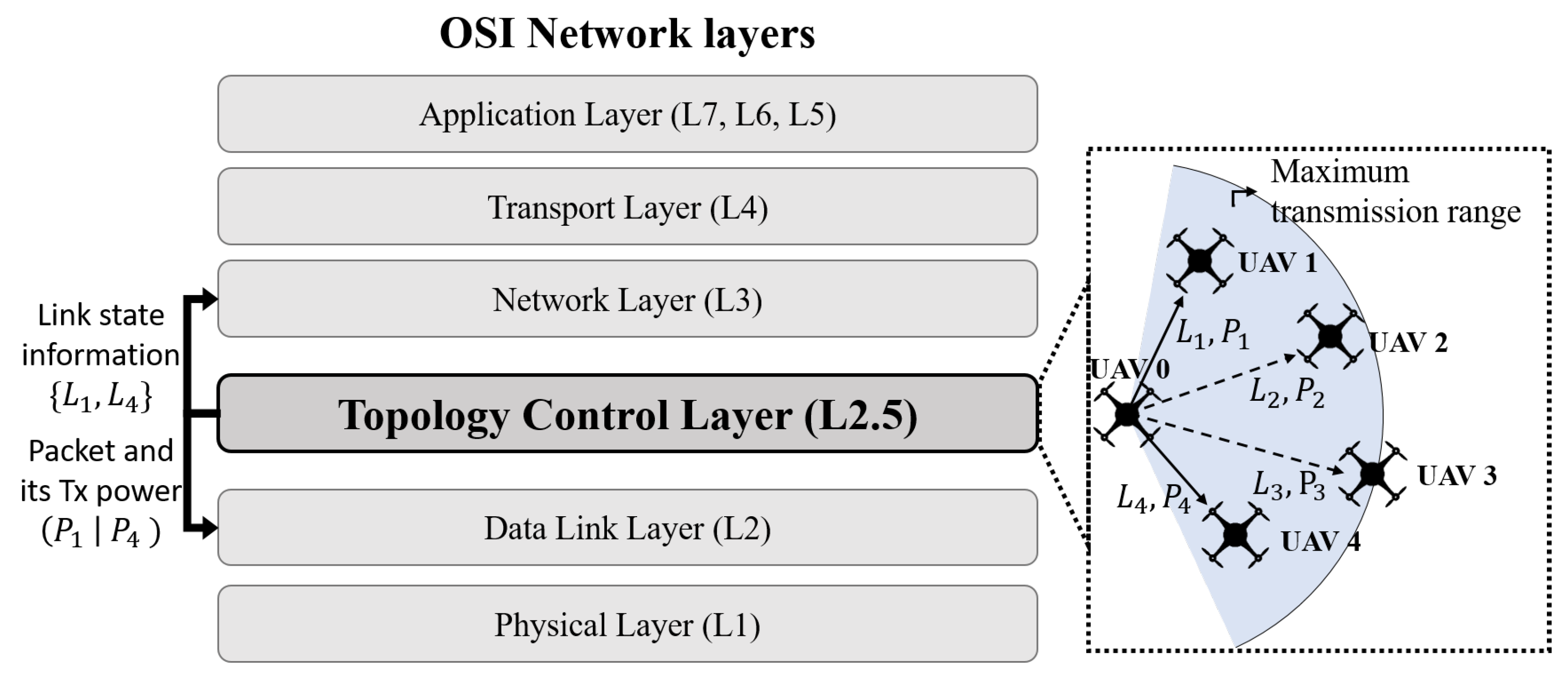
  • Our research can be compatible with other network layers in the OSI model. Also, the topology control layer acts just between the data link layer (L2) and network layer (L3), which possibly can be expressed as L2.5.
In the following sections, we provide further explanation of our research. In Section 2, we introduce previous research on UAV networking technology. In Section 3, we present our methodology that explains the system overview. The evaluation of our methodology is presented in Section 4, and Section 5 lists the discussions about the simulation results. Finally, we conclude our work in Section 6.

2. Related Work

Since UAV networking is an intensive technology that requires a variegated research domain, various research is being actively conducted in several ways. In this paper, recent research focusing on the various topics on UAV formation, energy-efficiency design, and the transmission power control is introduced in detail.
  • UAV formation: The construction of an appropriate formation with many UAVs is progressing in various aspects. In fact, UAV positioning algorithms have been studied in consideration of network throughput [13], obstacle collision avoidance [14], and mission conditions [15]. Sabino et al. [16] proposed the multi-UAV placement scheme through the genetic algorithm. It should be noted that UAV formation control algorithms can be joined with our proposed system, since our system aims to improve the network topology of UAVs, which have the potential to frequently change their shape in three-dimensional space. With our dynamic topology control scheme, the UAV network can sustain an energy-efficient network while changing each UAV’s position according to their mission.
  • Energy Efficiency: Research to improve the energy efficiency of the UAV network is proceeding by way of reducing the energy in the operation of UAV itself (e.g., optimized path planning for efficient aircraft propulsion), and the arrangement to minimize the energy on the entire network (e.g., optimal network recovery with additional UAV) [17]. In this paper, we compose an energy-efficient topology that is based on network management, which can be applied a priori to other related previous research.
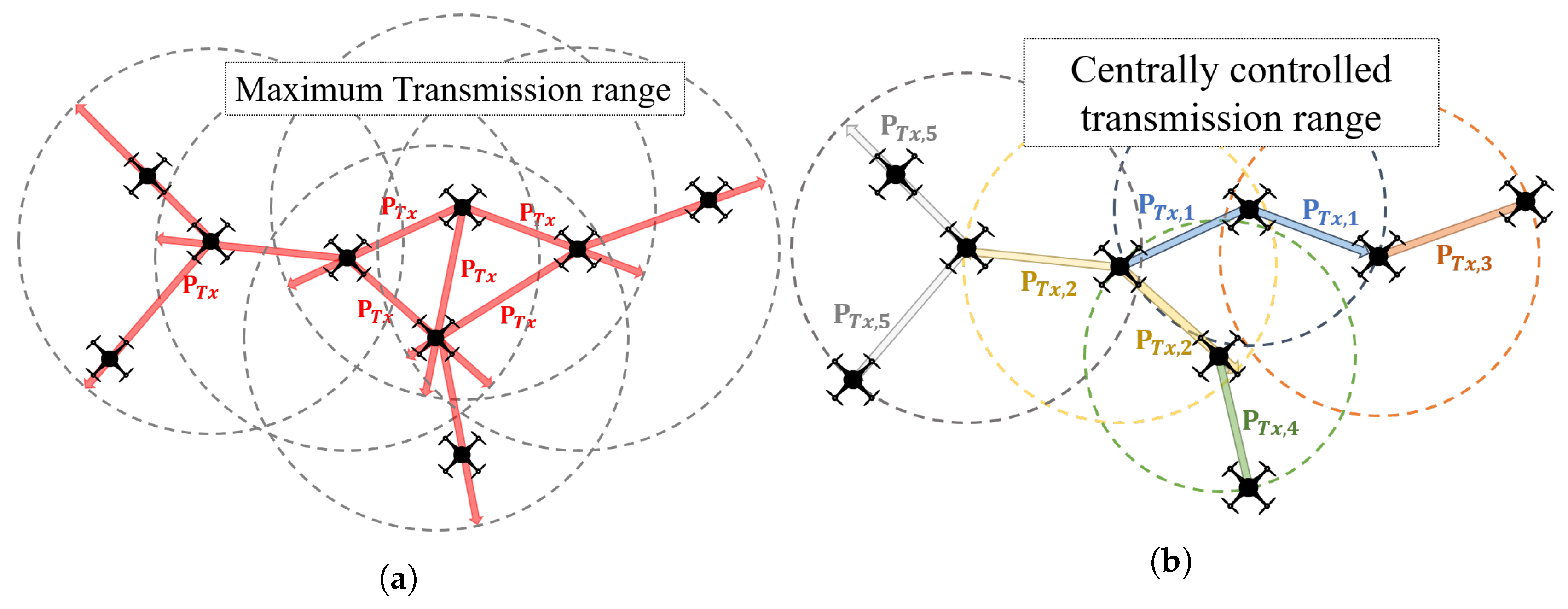
  • Transmission Power Control: Many studies have been made to change transmission strength according to its conditions for effective communication. For example, power-controlled multiple access MAC protocols (PCMA) were presented to improve the channel use [18], and a tunable circuit system was studied to generate range-adaptive transmit signals [19]. However, these studies have not been used for UAV networks with mobility characteristics. Moreover, these studies are still inefficient since all nodes in the transmission range attempt to connect without any adjustment. However, our research uses the transmission power control in the UAV network and forms the network by controlling the number of the available links.
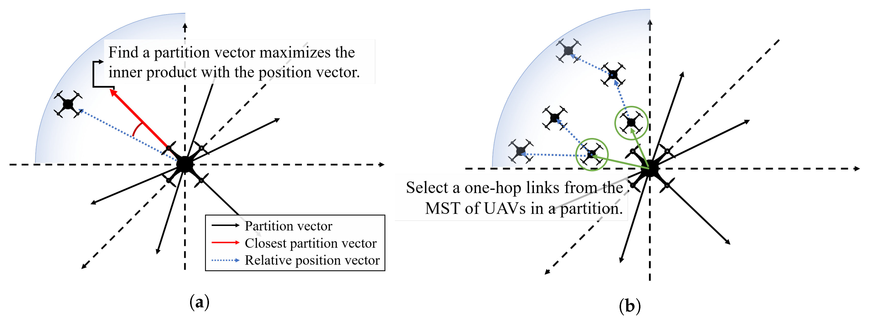
  • 3D topology control schemes: Emerging research on the unmanned vehicle system emphasizes the importance of the dynamic network control problem for expanding its usage. Continuously adapting the network topology in the 3D space has been largely studied for both energy efficiency and network quality. Zhang et al. [20] proposed a cluster sleep–wake scheduling algorithm for underwater sensor networks. One of the main differences with our system is that this algorithm produces an on–off schedule of the links, while our one results in selected links which guarantee global connectivity (Section 3.3). Also, it adopts a centralized partitioning concept, while each UAV partitions the space, centering itself, in our algorithm. Our distributed concept has the advantage of scalability of the network, since the processing overhead remains the same with larger-scale networks. Kim et al. [21] addresses the 3D topology control method considering interference. In this paper, Cone-Based Topology Control (CBTC) has been introduced for partitioning each node’s space. The major difference with our work is the group of the selecting nodes. Our system selects the adjacent UAVs of the MST constructed in each partition (Section 3.2), while CBTC selects only the nearest one in each partition. This difference shows the limitation of the number of partitions, where CBTC restricts the angle of the division section while our system does not. The flexibility of the number of partitions results in the variety of the partition models, which enlarges the adaptability of the network scale (e.g., density of the UAVs).
In summary, there has been research considering the energy consumption of the wireless UAV network. However, due to the lack of the cooperability and the compatibility with the other OSI layers, the UAV network is not fully beneficial when previous strategies are applied. In addition, some attempts at controlling the mobility of the UAV for networking energy efficiency might not be helpful when operating the UAVs in a practical scenario, since each UAV’s position decision will suffer from the confliction between the power efficiency and the mission performance. Our design adopts the distributed and reactive method, where each UAV collects neighbors’ locations and determines their available links and the transmission power for energy-efficient networking.

3. System Design

In this section, we address the design of the topology control layer. Our concept is an additional layer between the data link layer and the network layer, so it coordinates these layers to improve the energy efficiency of the network, by controlling the topology. Also, our design targets the distributed manner of the system, whose result guarantees a topology with high efficiency and complete connectivity. The following subsections explains our system components in detail.

3.1. Topology Control Layer

The topology control method that we propose is individually applied to each UAV in the network separately, but the final network appears as a comprehensive network topology. As shown in Figure 3, our topology control process is functioning between the network layer (L3) and the data link layer (L2). Since the topology control is compatible with various routing protocols in the network layer and many other flow control models in the data link layer, it can be well used in the conventional OSI network system. We assume that each UAV is equipped with a global navigation module, such as GPS, to determine the relative position between the UAVs. The topology control layer periodically broadcasts its position information, so each UAV can seize the nearby UAV positions. For example, as shown in Figure 3, let us assume that a UAV collects the positions of the four neighbor UAVs, from the beacon message reception by L2. The topology control layer filters out the link among these four available links, such as L 2 and L 3 , and reports the information of the link L 1 and L 4 to the L3. L3 operates its routing algorithm and creates the routing table. After L3 determines the link to send the packet, the topology control layer forwards the designated transmission power to L2, so the packet reaches the next hop or the destination with a proper amount of signal power. Note that if P 1 < P 4 , then there is a possibility that UAV 0 does not interfere with UAV 1 while using L 4 , which has advantages in the congestion release of the wireless medium.
Compared to the fully connected topology (e.g., Figure 1a), some advantages can be made when adopting topology control layer. First, transmission power per each link is adapted. Of course, enough of the transmission power is needed for higher throughput, but excessively large power can be redundant at the viewpoint of the network lifetime. Second, a routing table is simplified and more effective. Due to the link filtering of the topology control layer, the number of the routes decreases, so the routing table calculation overhead also decreases. On the other hand, compared to the global MST topology (e.g., Figure 1b), there are other improvements, as in the case of fully connected topology. Due to the packet-level power control, each UAV can handle more links than the MST case. Also, there are more capabilities to cope with the congestion or the failure of the links, since the topology control layer periodically observes the neighboring UAVs and considers the substitute route for networking.
Now, we should consider how to filter the links from the available ones. If the criteria of the filter are only the distances from the destination UAVs, then a part of the UAV network can be isolated due to unexpected link pruning, as shown in Figure 4. Section 3.2 discusses our strategy to build stabilized and efficient topologies by collecting only the positions of nearby UAVs.

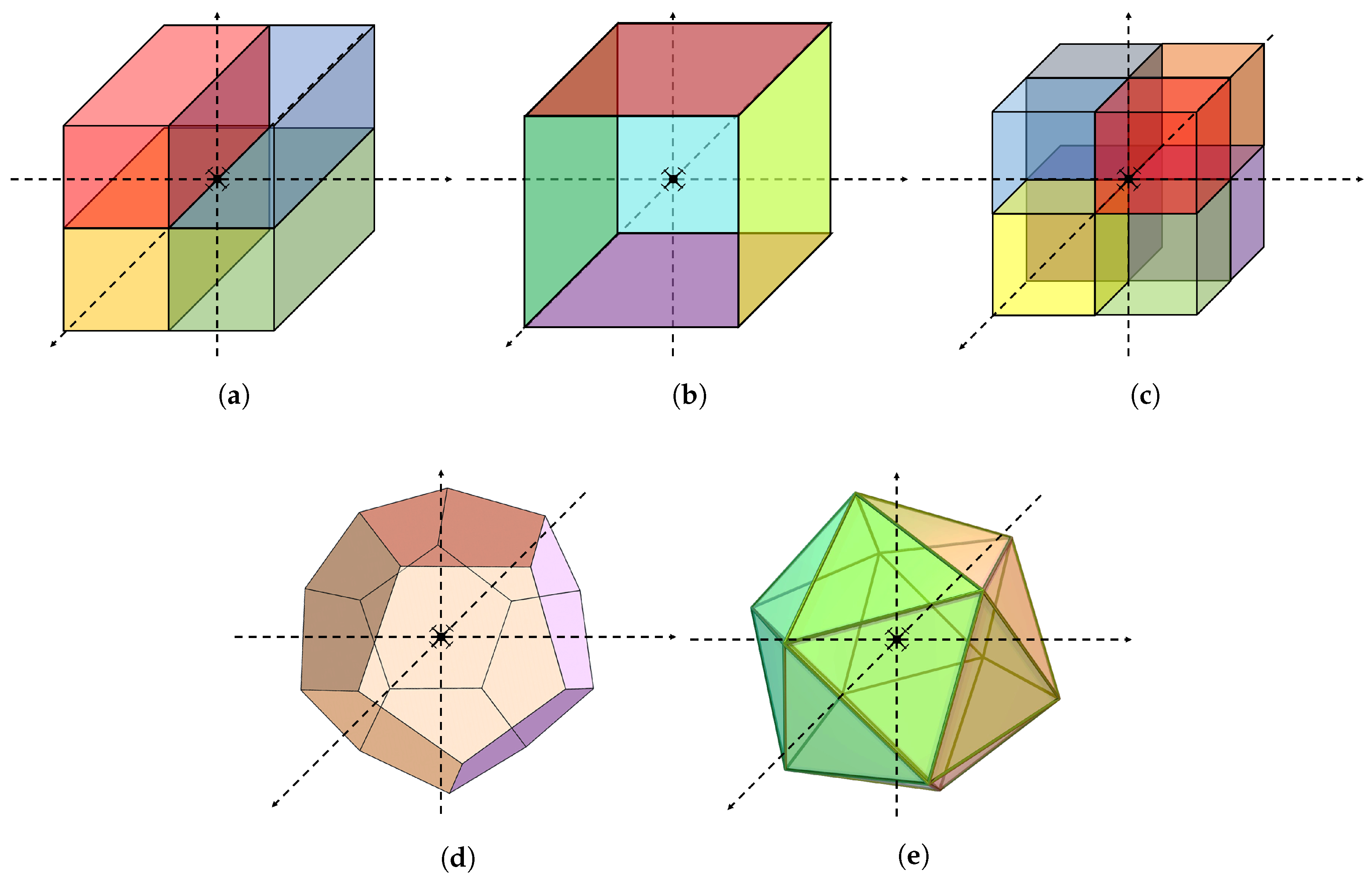
3.2. Space Partition Method

To distribute the neighbor links direction evenly, we propose a novel space partition method as a solution of the link selection problem. Assuming that the maximum transmission range of a UAV is shaped as a sphere, the spherical space can be divided into several partitions with the same volume, which includes the origin of the sphere. By selecting the closest links from each partition, the UAV gets a set of links that are evenly distributed in all directions. With this observation, we designed an algorithm for the proposed space partition scheme as shown in Algorithm 1.
Algorithm 1 Topology control layer.
1:
P ϕ                     ▹ Neighbors’ position vectors
2:
 
3:
functionNeighborUpdation
4:
  while exception occurred do
5:
     p 0 UpdatePos()
6:
    BroadcastPosition( p 0 )
7:
     P ReceiveBeaconMessages ()
8:
    Update P with P
9:
    Sleep for a cycle
10:
  end while
11:
end function
12:
 
13:
functionLinkSelection
14:
   S Normal vectors of n planes.            ▹ Partition vectors
15:
  while exception occurred do
16:
     A i ϕ where 0 < i < n
17:
     H i ϕ where 0 < i < n
18:
     T x i 0 where 0 < i < n
19:
    for p in P do
20:
      d p p 0
21:
      s arg max s S s · d
22:
      h IndexOf ( s )
23:
     append IndexOf( p ) in A h
24:
    end for
25:
    for i where 0 < i < n do
26:
     Construct an MST of the components in A i regarding p 0 as a root
27:
      H i the children of p 0
28:
      T x i GetTxOfRange ( H i )
29:
    end for
30:
    Sleep for a cycle
31:
  end while
32:
end function
Figure 5 shows the overall steps of Algorithm 1. Our proposed system runs two processes in parallel, the one addressed at lines 3 to 11, and the other one addressed at lines 13 to 32. The system globally allocates a memory to monitor the location of the nearby UAVs in the maximum transmission range, named P. The function NeighborUpdation periodically broadcasts the beacon message containing its position information, and receives the nearby UAV’s beacon message to update P. With the updated position information, the function LinkSelection prunes the links according to the space partition method and designates the transmission power of each link. We address the sequence of the algorithm in detail.
At first, the algorithm should secure a set of vectors S, which contains the vectors, each of which projects the partitioned surface of a sphere, known as partition vector. To get S, we divide the sphere sized with the maximum transmission range into n partitions. For the uniform distribution of the links, we set ground rules for partitioning:
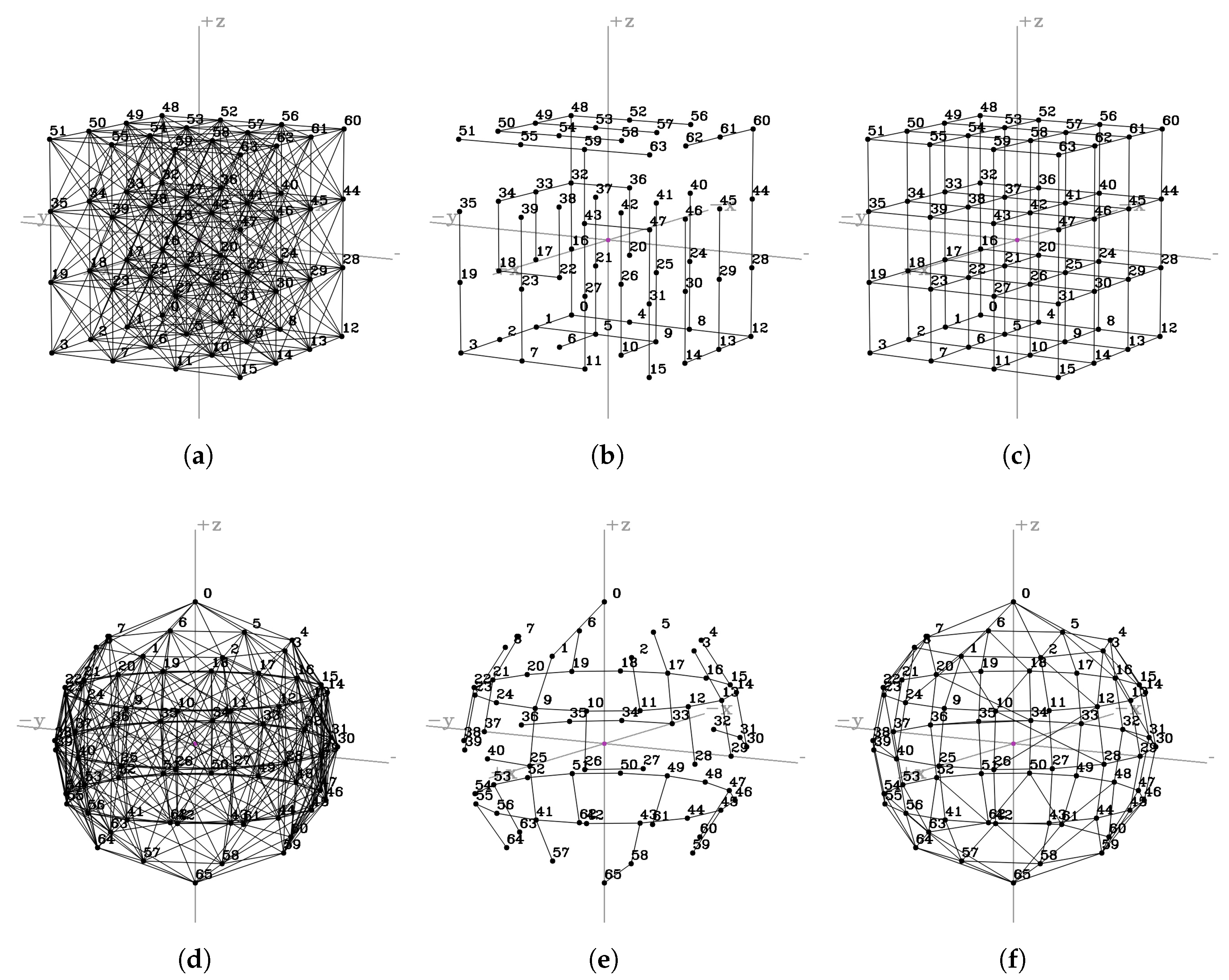
  • The partitions should have the same volume.
  • The partitions should contain the origin of the sphere.
  • The partitions should have the same area of the surface.
The examples of the partitioning are represented in Figure 6, where n = { 2 , 4 , 8 , 12 , 20 } . For visibility, we expressed the partitions as the shape of the original ingredients of the solid figure, such as cube, icosahedron, and so on. The actual partitions are the ones trimmed by the sphere inscribed in the colored solid. For instance, if n = 2 , a set S is composed of two vectors, which are ( 1 , 0 , 0 ) and ( 1 , 0 , 0 ) , respectively. On the other hand, if n = 8 , a set S is composed of eight vectors, which are ( ± 1 , ± 1 , ± 1 ) . In the cases of n = 12 and n = 20 , we used known regular polyhedrons which have the same area of the faces and can be closely fitted to the sphere, such as dodecahedron and icosahedron, respectively. The normal vectors of each case can be derived from the known equations, such as
S = { ( ± 1 , ± 1 , ± 1 ) , ( 0 , ± ( 1 + h ) , ± ( 1 h 2 ) ) , ( ± ( 1 + h ) , ± ( 1 h 2 ) , 0 ) , ( ± ( 1 h 2 ) , 0 , ± ( 1 + h ) ) } w h e r e h = 5 1 2 ,
when n = 20 .
Topology control layer periodically updates the position of nearby UAVs by NeighborUpdation, and determine what partition each UAV belongs to, in LinkSelection. For each UAV’s position p , the algorithm derives d = p p 0 , and selects a normal vector s from S which results the maximum inner product value with d (Figure 5a). After categorizing all links, the algorithm constructs an MST composing the UAV itself and the other UAVs in each partition, then collects the one-hop links from them (Figure 5b). Finally, the UAV reserves the number of the selected links, each of which is the nearest UAV in a partition. In the aforementioned case of Figure 4, the far-range link will be one of the selected one, since the neighbor UAV is within a transmission range, and it will be the only one link of a specific partition.
After the suggested topology control process, multi-hop communication can be performed with any desired routing protocol. For instance, the shortest path algorithm, such as the Dijkstra or Bellman–Ford algorithm, can be used to derive the routing path to the other UAV connections in distributed routing protocols. As an overall assessment, our topology control method can reduce the number of unnecessary links by effectively dividing the surrounding space into several partitions. Also, it has an advantage in transmission power because each UAV only needs to consider the nearest UAVs.

3.3. Connectivity Proof

We show the connectivity of the resulting topology of Algorithm 1 derived from the given deployment of UAVs. We preliminarily assume that any of the deployed UAVs has one or more nearby UAVs in its maximum transmission range. We first prove local connectivity among the neighbors in the maximum transmission range of UAV. Then, we eventually prove global connectivity by finding a knock-on path from two arbitrary UAVs u to v, referred to P ( u , v ) = < u , h 1 , h 2 , h 3 , , h m , v > . This global connectivity is significantly derived from UAVs’ previous local connections. In terms of the resulting topology of our system, we derive the following two theorems about connectivity.
Theorem 1
(Local connectivity). The result of Algorithm 1 guarantees the connectivity between a UAV and its neighbor UAVs within the maximum transmission range.
Proof of Theorem 1.
This theorem shows the UAV connectivity between an arbitrary UAV u and its neighbor UAVs, all of which are within one maximum transmission range from the UAV u itself. Let M T R u refer to a set of the UAVs located within the maximum transmission range, where w M T R u . Also, let N H u refer to a set of selected links by u in Algorithm 1, where N H u M T R u .
w M T R u , Case ( i ) : w N H u P ( u , w ) = < u , w > Case ( ii ) : w N H u there   always   exists w 1 such   that w 1 N H u and P = < u , w 1 > is   a   subpath   of P u ( u , w ) , which   is   derived   by   an   MST   constructed   in   line   26   of   Algorithm   1 . We   let u = w 0 , and   applying   Algorithm   1   to   each w i , then   there   exists w k 1 such   that w k = w . By   chaining   all   the   discovered   subpaths , P T o t a l = P ( w 0 ( = u ) , w 1 ) P ( w 1 , w 2 ) P k ( w k 1 , w k ( = w ) ) = P ( u , w ) . Thus , the   path P ( u , w ) = < u , w 1 , w 2 , , w k 1 , w > exists .
 □
Figure 7 graphically represents the above sequence. By this procedure, the connectivity with all UAVs in every partition of arbitrary chosen UAV u is always guaranteed. Thus, the connection is guaranteed for all UAVs in the maximum transmission range of UAV u.
Theorem 2
(Global connectivity). The result of Algorithm 1 guarantees the connectivity of two arbitrary UAVs network-wide.
Proof of Theorem 2.
We prove the global connectivity with Theorem 1. We let G ( V , E ) refer to the graph representing a fully connected UAV network, where V is the set of UAVs and E is the set of edges defined by the reachability between two UAVs with the maximum transmission range. Also, G T C ( V , E T C ) refers to the graph representing the resulting network topology of topology control layer, where E T C is the set of edges that Algorithm 1 selects. The other notations mean the same as aforementioned.
Assume   there   is   a   path P ( u , v ) = < u ( = h 0 ) , h 1 , h 2 , , v ( = h n ) > in G ( V , E ) . Each   pair   of   subsequent   UAVs   in P ( u , v ) , such   as ( h i , h i + 1 ) ( i = 0 , 1 , , n 1 ) , is   replaced   with   a   path < h i , w 1 , w 2 , , w k 1 , h i + 1 > , owing   to   Theorem   1 . Therefore , if P ( u , v ) is   in G ( V , E ) , then P ( u , v ) is   also   in G T C ( V , E T C ) .
 □

3.4. Swarm Intelligence Point of View

We designed our proposed topology control to inherently contain the concept of swarm intelligence (SI). We made a simple rule for each UAV in the network, but the overall topology consequently shows robust connectivity, as proven in Section 3.3. Also, the ingredients to make decisions can be fairly collected in a distributed manner, where every UAV equally broadcasts its location. With changes to nearby environments, the UAV can dynamically change its link selections and designate the proper transmission power of the targeted end-to-end connections. Our accomplished SI concept yields the following advantages.
  • Scalability. Compared to centralized methods, our proposed system does not need any centralized protocols or regulations. This feature prominently appears when the maximum hop count increases due to a large-scale network, where farthest UAVs take much longer to update its network configuration in the centralized system. In the topology control layer, each UAV determines the next available hops by itself, so the network size does not affect the network configuration delay.
  • Mobility. Considering the high mobility of the UAV, our distributed concept based on the location has strong advantage during network topology changes. Since each UAV periodically updates its available neighbors, a network layer can rapidly drop or append the available links without hesitation.
  • Simplicity. In the case of the micro UAVs, the computational resource is too small to input the high intelligence necessary for networking [22]. Our proposed system is composed of simple calculations augmented at the existing network stack, so it has much less occupancy of the system resources, which also contributes to the energy efficiency.

4. Evaluation

We implemented our proposed space partition method (Algorithm 1) and the network topology simulation written in Python, and measured the numerical data to plot the results using MATLAB. We used OpenCV library to display the network topology for various cases. Also, we compared our scheme with the following network topologies to present the advantages of applying the topology control process to the UAV fleet network.
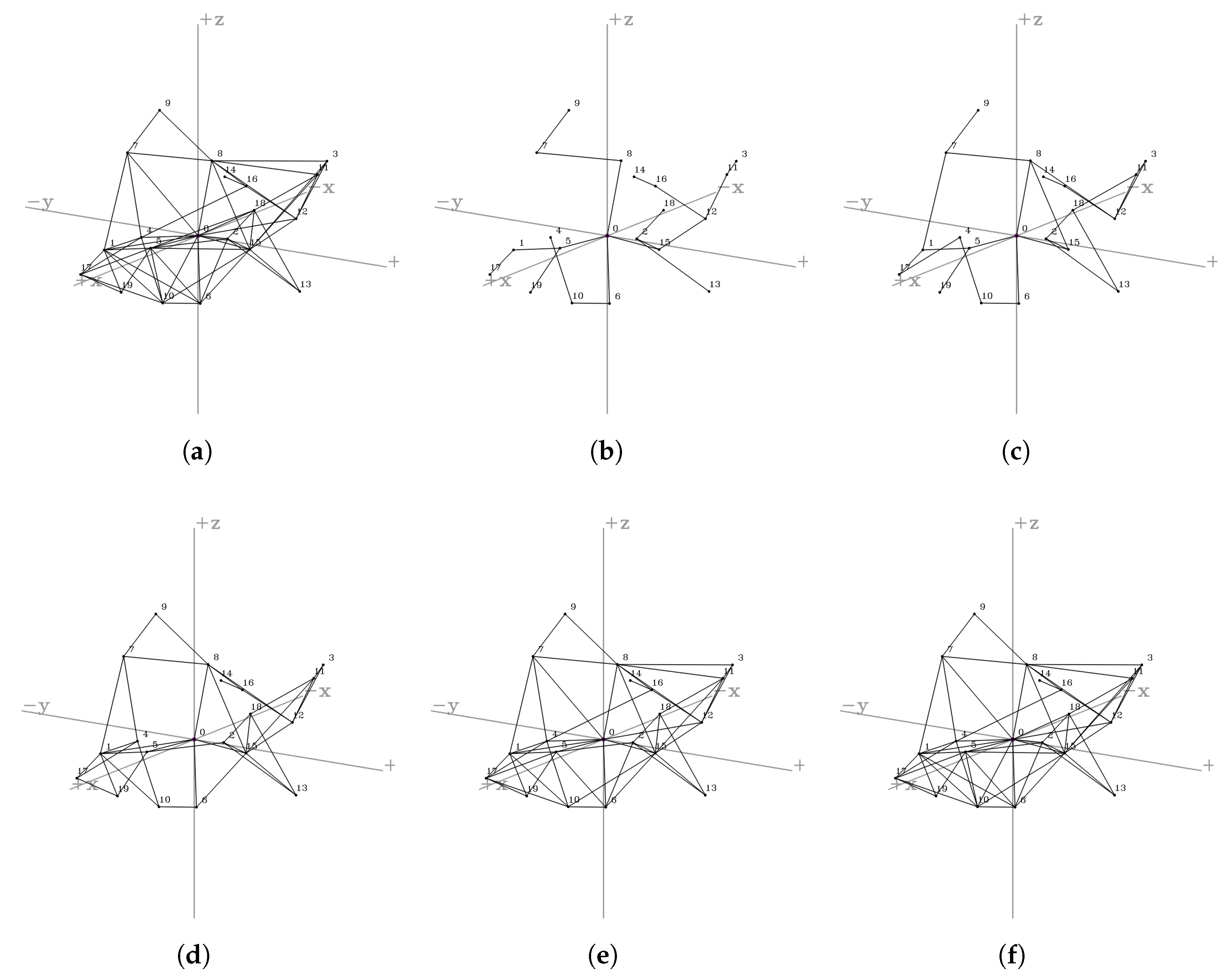
  • Fully connected (FC): UAV networking that is fully connected with all UAVs that are in their transmission range.
  • Simple MST (SMST): UAV networking appending the simple minimum spanning tree method.
  • Topology Control (TC): UAV networking with a proposed topology control method. For each n value, we abbreviate the TC with n partitions as TC-n.
To examine the performance of the resulting topologies, we simulated a routing scenario for each case. We randomly sampled 50 % of the existing UAVs, and searched the optimal route from each to all the other ones. We adopted Dijkstra algorithm [23] to find the shortest path to the target destinations. As mentioned in Section 3.1, our topology control algorithm can be any other path-finding algorithms, such as congestion-free ad hoc routing strategies discussed in [24]. Also, we set the distance between the UAVs as a link cost used in our Dijkstra algorithm, so the result of the algorithm is the most energy-efficient paths with respect to the topology of FC, SMST, and TC-n.
We claim that our exhaustive search can thoroughly validate the performance of the network topology, along with the stability, energy efficiency, and the network traffic. Commonly used routing protocols aim to optimize the routing table of each device. Analysis of the Dijkstra algorithm result shows the best path of each end-to-end connection derived from the network topology, so we derive the statistics from the optimal path to every UAV in the network. We evaluate the network topologies by the following metrics.
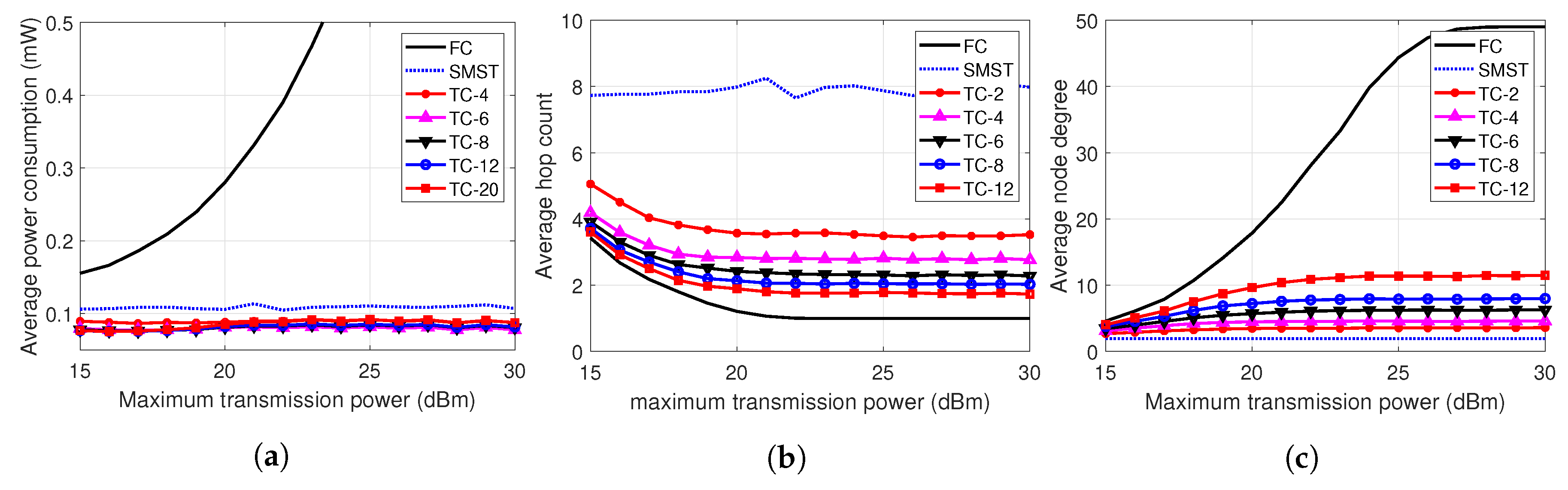
  • Node degree: We exploit one of the general terms used in the graph theory. In this paper, the term node degree refers to the number of the edges which are incident to a UAV. At the viewpoint of the network topology, high node degree implies high stability of the network. If one of the connected neighbor UAVs fails (due to the emergency landing or return to home), the UAV should use the other connections to sustain the network connectivity. However, if UAVs have low degrees, the network has higher potential to lose the whole connectivity even with the loss of some centric nodes.
  • Hop count: Hop count of an end-to-end connection is the number of the edges of the optimal path between them, which can be derived by the aforementioned Dijkstra algorithm. Higher hop count not only increases the delay of the connection but also has the potential to drop the end-to-end throughput, since the packet is repeatedly propagated through the wireless medium per each hop. Thus, lower hop count results in less use of the wireless medium with low latency, which results in the overall throughput improvement of the UAV network.
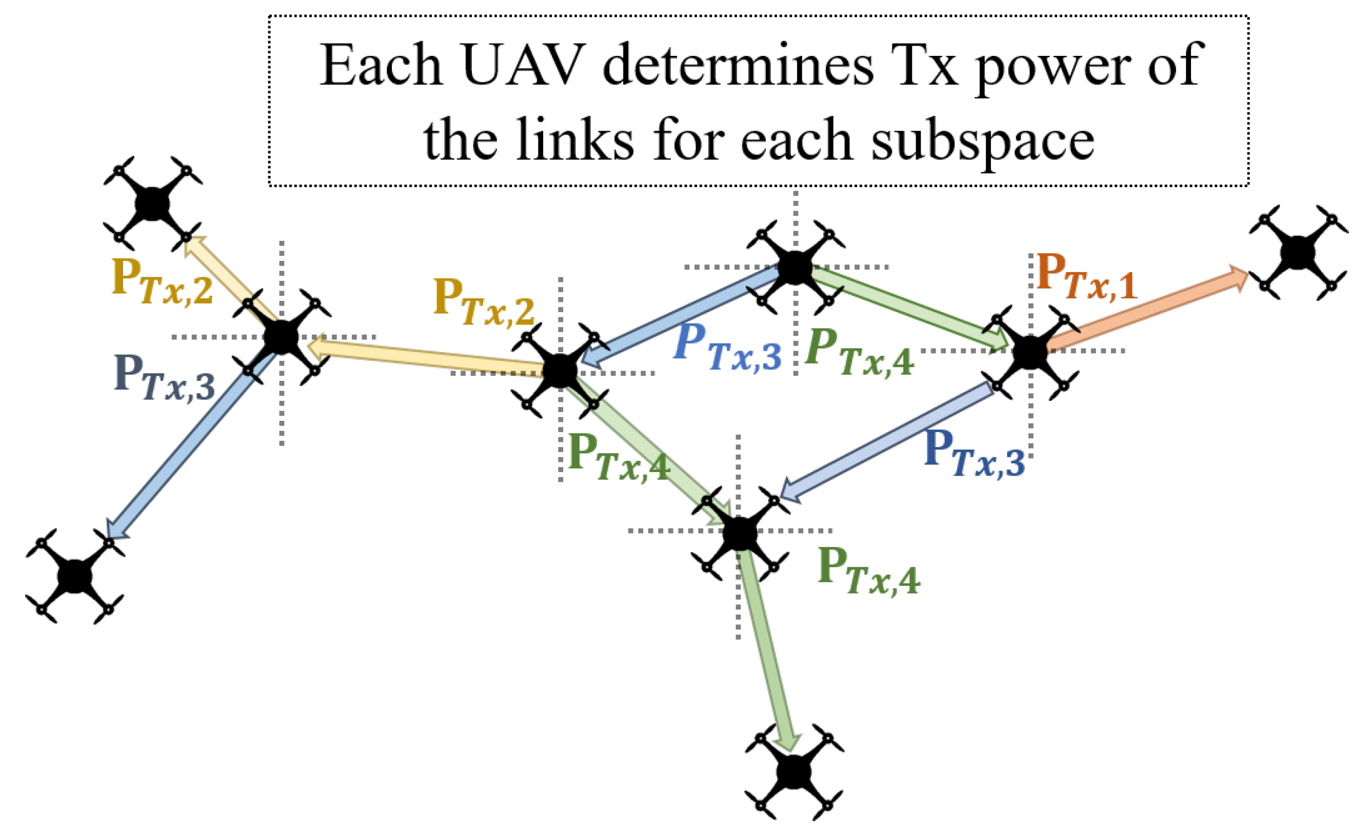
  • Power consumption: As discussed in Section 3, our proposed system determines the transmission power of each link. We summed the amounts of the transmission power required at all links on each end-to-end connection. In the case of FC, we assumed there is no power control method equipped, so the expected power consumption is the multiplication of the average hop count by the maximum transmission power. On the other hand, in other cases, the transmission power of each link is calculated from the distance using the Friis equation. Please note that excessively high hop count results in the higher power consumption of the end-to-end communication, despite the low power consumption due to the short distance of the links.
We evaluate the network topologies while varying the number of UAVs, maximum transmission power, shape of the formation, and the number of the partition n. Default value of each parameter is listed in Table 1. The following subsections discuss the evaluation result while varying the parameters.

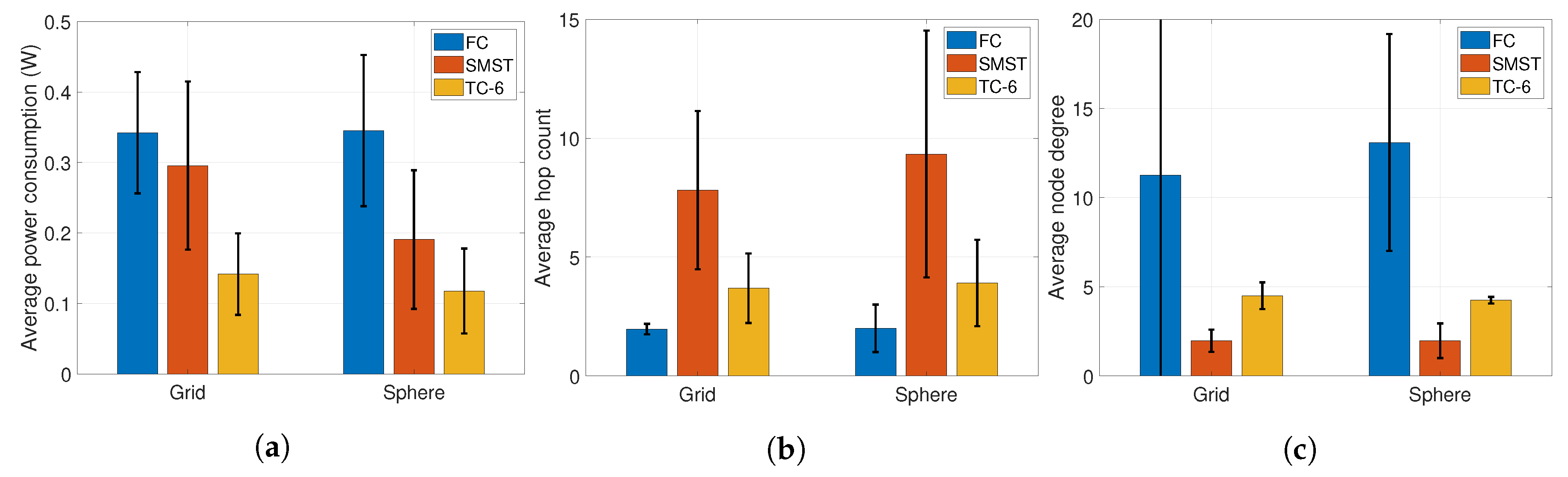
4.1. Regular Formations
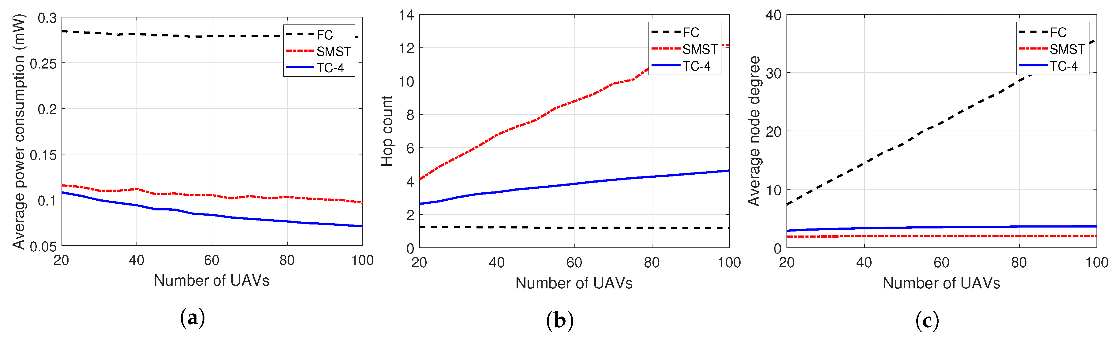
To effectively show the resulting shape of the network topology of our system, we first conducted the evaluation with the regular formation of the UAVs, such as grid-shape or sphere-shape. Figure 8 shows the three-dimensional representation of each network topology. In the case of the grid formation, we deployed 4 × 4 × 4 UAVs with the default size of the map space, and the same distance of the width, height and depth between the nearby UAVs. In the case of the sphere formation, we deployed 66 UAVs in the surfaces of 3 concentric spheres. As shown in the Figure 8a, if all UAVs fully connect to the nearby UAVs in its maximum transmission range, the topology gets highly complex and this may lead to high interference in the wireless medium. On the other hand, the case shown in Figure 8b shows an MST including the network, which could lead to the high hop count of some connections, such as the route from 51 to 46, which has 17 hops. The topology result of our proposed topology control layer is shown in Figure 8c, which represents visually expected connections at this grid formation. The reason for the result is that the topology control layer only leaves the nearest link from each partition. While the fully connected cases in Figure 8a,d suggest the intensive traffic on the center of the network, the TP-6 cases in Figure 8c,f reduce this potential by filtering the further connections of each UAV and controlling the transmission power of each link. As shown in the topologies in Figure 8, we showed how our proposed system forms the topology of the UAV network, compared to the other comprehensive or centralized methods.
Figure 9 shows the evaluation results of the network topologies shown in Figure 8. We measured the average and the confidence interval of the power consumption, hop count of end-to-end connections, and the node degree of the UAVs. As shown in Figure 9a, TC-6 outperforms the other cases FC and SMST, while showing less than a half of the power consumption of the other cases. It is remarkable that TC-6 shows much less power consumption than SMST, which grants centralized optimal topology of the whole UAV network. The reason for this outperformance is mainly due to the advantage in the hop counts (Figure 9b), since larger hop count of the SMST case leads to more frequent transmissions, which incurs the large amount of the power consumption despite the low transmission power. By numerical comparison, we showed our proposed topology control layer can reduce the power consumption of the UAV network, through the efficiently constructed network topology. In the following graphs, for better visibility, we omitted the confidence interval of the results, which shows almost similar tendencies to the remaining evaluations.
To show the differences in the network topology while varying n at the general case, we ran our proposed system in a random formation, as shown in Figure 10. In this figure, we deployed 20 UAVs in the map with uniform random distribution. As shown in the subfigures, when n increases, the shape of the network topology gets closer to the FC case, as TC-20, shown in Figure 10f. Please note that UAVs select at most n UAVs as their next hops in each partition, which has smaller size at larger n. The case of larger n has more chance to grab the UAVs in the transmission range as their next hops, so larger n acts as similar to the FC case. However, the expected power consumption of the end-to-end connection is smaller than the FC case even though larger n cases, since topology control layer designates the transmission power of the links. In the following subsections, we evaluate our system while varying the numerical parameters, to show how the parameters affect the performance of the topology control layer.

4.2. Network Size

Figure 11 shows the average of the power consumption, hop count and degree while varying the number of the UAVs from 20 to 100. We compared the case of FC, SMST, and TC-4 for each performance metric. The other parameters for the simulations are set as default, listed in Table 1. As shown in Figure 11a, TC-4 shows higher decrement ratio of the power consumption than the other cases. This is due to the unique property of the topology control layer, which adopts the transmission power of each link, while sustaining the number of the nearby links. Increasing the number of the UAVs leads to the decreases of the average distances between the UAVs. In the case of SMST, this decrement results in the low transmission power of the links just as TC-4, due to centralized topology generation. However, due to the properties of the minimum spanning tree, higher density of UAVs inevitably causes higher hop counts, which is shown in Figure 11b. As mentioned before, increasing hop count consequently increases the power consumption of the end-to-end connection, which results in relative inefficiency as in Figure 11a. On the other hand, the case of FC sustains smaller hop count and larger degree (Figure 11c) than the other cases, but it has much higher power consumption due to the fixed and excessive amount of the transmission power. Furthermore, a larger degree of UAVs indicates higher robustness, but also brings the potential for more congestion and the collision of the frames. Figure 11c shows that the case of FC steadily increases the degree of UAVs, which leads to the degradation of the throughput and the efficiency of the transmission. In summary, the results in Figure 11 proved that the topology control layer yields a moderated degree and hop count, which results in it outperforming the power efficiency of the UAV network.

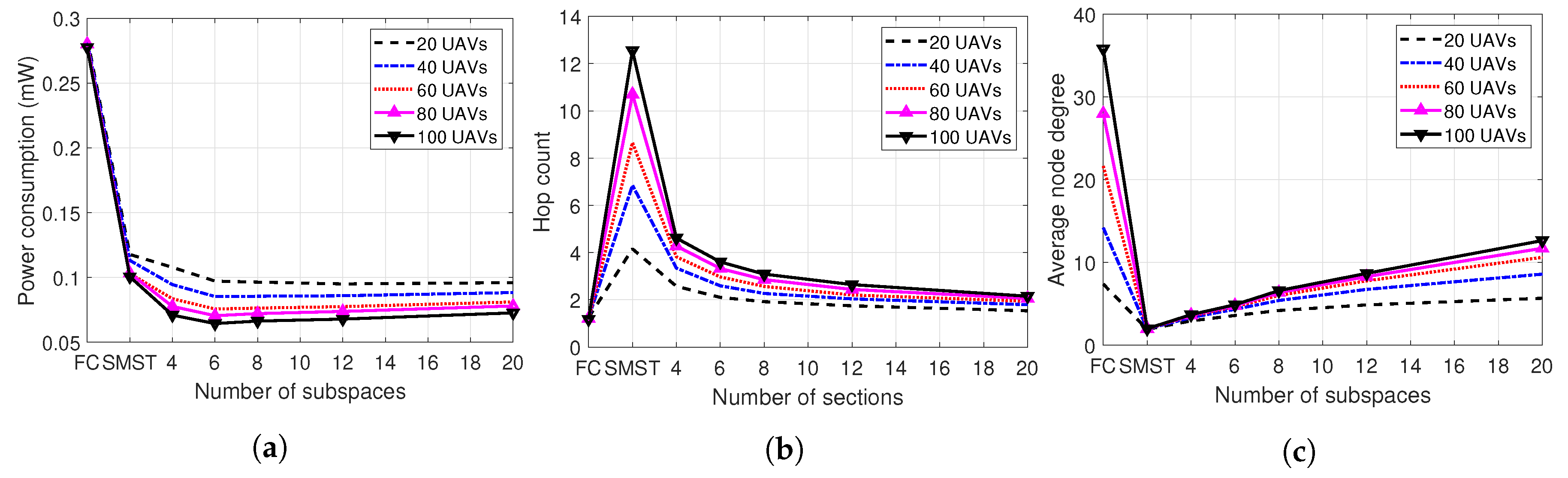
4.3. Number of Partitions

We also measured the results while varying the number of the partitions, where n = { 2 , 4 , 6 , 8 , 12 , 20 } . As shown in the subfigures in Figure 12, the cases of TC-n outperform the other cases (FC, SMST) in power consumption. In the case of the hop count and the degree, TC-n shows the medium values between the FC and the SMST, since the topology control layer prunes the links regarding to the number of the partitions. On the other hand, as n increases, hop count decreases and the degree increases. Due to the increase of the possible links in larger n, there are more chances to decrease the hop count with the larger number of partitions. Furthermore, it is notable that the average power consumption of end-to-end connection is minimum at n = { 6 , 8 } , regardless of the number of the UAVs. However, it is hard to conclude that the network is optimal at a certain n, since the larger n results in lower hop count, which leads to the improvement of the expected throughput. In conclusion, the results in Figure 12 show that there is an optimal n value for the desired objective of the UAV network.

4.4. Transmission Range

We varied maximum transmission power of 50 UAVs, in various n values. Figure 13 shows the numerical results compared to FC and SMST cases. In Figure 13a, we cut the transmission power over 0.5 mW for visuality. The results in this figure have several considerations. At first, while FC cases have exponentially increasing power consumption when the maximum transmission power increases, the cases of SMST and TC-n have mostly constant power consumptions. This result indicates that SMST and TC-n can sustain similar efficiency in various cases of the maximum transmission power. Then, the outperformance of the TC-n against the SMST originates from the packet-level power control and the partitioning-based link pruning, as mentioned in the former subsections. Secondly, there is a saturation while increasing the maximum transmission power, after about 22 dBm, both in the hop counts and the degrees. The reason for this phenomenon is that the nearest neighbors of certain directions are selected despite the transmission range expansion. For this reason, the saturation starts earlier when n is smaller, as shown in Figure 13b,c. The saturation indicates that our topology control layer outperforms results even at the smaller transmission range.
We summarize our simulation results as follows.
  • We evaluated our proposed system topology control layer while varying the network size, number of partitions, and the transmission power. In every evaluation, our system shows outperforming results in average power consumption, while sustaining moderate values of the average node degrees and the hop counts.
  • While varying the network size, the topology control layer shows a larger decrement in power consumption, because our system keeps a proper number of links and fits the transmission power of them.
  • While increasing the number of the partitions, hop count shortly decreases and degree shortly increases due to the larger number of the selected links. In Figure 12a, TC-6 and TC-8 nearly show the lowest amount of the average power consumption regardless of the number of UAVs.
  • Increasing the transmission range results in great advantages in power consumption, compared to the FC case. Also, we found that power consumption of lower n is relatively small in a large transmission range, while the consumption of higher n is relatively small in small transmission ranges.
From the aforementioned statements, we claim that the topology control layer can contribute to the energy-efficient communication in the UAV network, in wide range of the environments.

5. Discussions

This section addresses additional discussions for topology control layer. We listed our considerations as following.
  • Multi-input, Multi-output (MIMO) adaptation. MIMO targets concurrent communications in several directions, which fits our concept well. Through the combination with MIMO technology, each UAV can use the links of several partitions concurrently, which leads to great improvement in network throughput. If MIMO capacities (number of the available concurrent transmissions) differs from the number of the partitions (n), the difference can be handled by the partition scheduling.
  • Link space improvement. If UAVs are flying in obstacle-rich environments such as an urban canyon, the relative distance between the UAVs does not directly refer to the link cost. Also, with the link quality improvement strategies such as packet recovery mechanism [25], a simple, distance-based space partition method cannot result in optimal network topology. To embrace these cases, we can design the space considering more than the positions, which can result in a more than 3-dimensional space. By formatting the partition vectors for the augmented space, our topology control layer can operate as Algorithm 1.
  • n granularity. In Section 3.2, we listed some of the n values, based on the regular polyhedrons derived before. If we can design more S with variable n values following the basic rules in Section 3.2, there are more possibilities to control n in detail, which is advantageous according to Section 4.4.
  • Empirical evaluation. In Section 4, we measured the performance of the network topologies with our own simulator, which is specialized to measure the property of the topology with power consumption. In this paper, we intended to focus on the clarified improvements in terms of the network topology, so we developed a simulator letting the numerical results be directly derived from the resulting network topology. By inserting our intermediate layer in practical network designs, we can evaluate our proposed scheme into a variety of network environments, by actually implementing devices or the public domain network simulator such as Network Simulator 3 (ns-3).
  • Applications. As our topology control scheme acts as an intermediate layer between the data link layer and the network layer, it can be broadly used in a wireless network domain. In the case of the UAV network, our system can contribute to performance improvements in multi-UAV surveillance [3], where extending the mission time and guaranteeing the quality of the video transmission service are essential. In addition, our topology control can be deployed in the Wireless Sensor Network (WSN) scenario since the WSN nodes commonly have intensive power constraints. Due to the compatibility of the system, our proposed scheme can be the breakthrough to solve energy-efficiency and performance-degradation problems in wireless network domains.

6. Conclusions

This study proposed a topology control method for energy-efficient UAV networks. Our system acts as an intermediate layer between the network and data link layer, so it is tolerant of any other network environments. By numerical evaluations, we showed that our space partition method highly reduces the power consumption of the end-to-end connections, while maintaining the node degree and the hop count in a proper amount. We hope that our approach based on the space partition inspires UAV network research domains.

Author Contributions

Conceptualization, H.K.; methodology, S.P., H.T.K., and H.K.; software, S.P., H.T.K., and H.K.; validation, S.P., H.T.K., and H.K.; formal analysis, S.P., H.T.K., and H.K.; investigation, S.P., H.T.K., and H.K; resources, S.P. and H.T.K.; data curation, S.P. and H.T.K.; writing–draft preparation, S.P. and H.T.K.; writing–review and editing, S.P., H.T.K., and H.K.; visualization, S.P. and H.T.K; supervision, H.K.; project administration, H.K.; funding acquisition, H.K.

Funding

The authors gratefully acknowledge the support from Nano UAV Intelligence Systems Research Laboratory at Kwangwoon University, originally funded by Defense Acquisition Program Administration (DAPA) and Agency for Defense Development (ADD).

Conflicts of Interest

The authors declare no conflict of interest. The founding sponsors had no role in the design of the study; in the collection, analyses, or interpretation of data; in the writing of the manuscript, or in the decision to publish the result.

Abbreviations

The following abbreviations are used in this manuscript:
UAVUnmanned Aerial Vehicle
FCFully Connected
SMSTSimple Minimum Spanning Tree
SISwarm Intelligence

References

  1. Hambling, D. Swarm Troopers: How Small Drones Will Conquer the World; Archangel Ink: Venice, FL, USA, 2015. [Google Scholar]
  2. Chung, A.Y.; Jung, J.; Kim, K.; Lee, H.K.; Lee, J.; Lee, S.K.; Yoo, S.; Kim, H. Poster: Swarming drones can connect you to the network. In Proceedings of the 13th Annual International Conference on Mobile Systems, Applications, and Services, MobiSys 2015, Florence, Italy, 19–22 May 2015; Association for Computing Machinery, Inc.: New York, NY, USA, 2015; p. 477. [Google Scholar]
  3. Jung, J.; Yoo, S.; La, W.; Lee, D.; Bae, M.; Kim, H. Avss: Airborne video surveillance system. Sensors 2018, 18, 1939. [Google Scholar] [CrossRef] [PubMed]
  4. Gupta, L.; Jain, R.; Vaszkun, G. Survey of important issues in UAV communication networks. IEEE Commun. Surv. Tutor. 2015, 18, 1123–1152. [Google Scholar] [CrossRef]
  5. Bekmezci, I.; Sahingoz, O.K.; Temel, Ş. Flying ad-hoc networks (FANETs): A survey. Ad Hoc Netw. 2013, 11, 1254–1270. [Google Scholar] [CrossRef]
  6. Li, X.; Guo, D.; Yin, H.; Wei, G. Drone-assisted public safety wireless broadband network. In Proceedings of the 2015 IEEE Wireless Communications and Networking Conference Workshops (WCNCW), New Orleans, LA, USA, 9–12 March 2015; IEEE: Piscataway, NJ, USA, 2015; pp. 323–328. [Google Scholar]
  7. Kagawa, T.; Ono, F.; Shan, L.; Takizawa, K.; Miura, R.; Li, H.B.; Kojima, F.; Kato, S. A study on latency-guaranteed multi-hop wireless communication system for control of robots and drones. In Proceedings of the 2017 20th International Symposium on Wireless Personal Multimedia Communications (WPMC), Bali, Indonesia, 17–20 December 2017; IEEE: Piscataway, NJ, USA, 2017; pp. 417–421. [Google Scholar]
  8. Katila, C.J.; Okolo, B.; Buratti, C.; Verdone, R.; Caire, G. UAV-to-Ground Multi-Hop Communication Using Backpressure and FlashLinQ-Based Algorithms. In Proceedings of the 2018 IEEE 29th Annual International Symposium on Personal, Indoor and Mobile Radio Communications (PIMRC), Bologna, Italy, 9–12 September 2018; IEEE: Piscataway, NJ, USA, 2018; pp. 1179–1184. [Google Scholar]
  9. Ebert, J.P.; Wolisz, A. Combined tuning of RF power and medium access control for WLANs. Mob. Netw. Appl. 2001, 6, 417–426. [Google Scholar] [CrossRef]
  10. Ebert, J.P.; Stremmel, B.; Wiederhold, E.; Wolisz, A. An energy-efficient power control approach for WLANs. J. Commun. Netw. 2000, 2, 197–206. [Google Scholar] [CrossRef]
  11. Iwai, K.; Ohnuma, T.; Shigeno, H.; Tanaka, Y. Improving of Fairness by Dynamic Sensitivity Control and Transmission Power Control with Access Point Cooperation in Dense WLAN. In Proceedings of the 2019 16th IEEE Annual Consumer Communications & Networking Conference (CCNC), Vegas, NV, USA, 11–14 January 2019; IEEE: Piscataway, NJ, USA, 2019; pp. 1–4. [Google Scholar]
  12. Lee, W.; Lee, J.; Lee, J.; Kim, K.; Yoo, S.; Park, S.; Kim, H. Ground Control System Based Routing for Reliable and Efficient Multi-Drone Control System. Appl. Sci. 2018, 8, 2027. [Google Scholar] [CrossRef]
  13. Ur Rahman, S.; Kim, G.H.; Cho, Y.Z.; Khan, A. Positioning of UAVs for throughput maximization in software-defined disaster area UAV communication networks. J. Commun. Netw. 2018, 20, 452–463. [Google Scholar] [CrossRef]
  14. Wang, X.; Yadav, V.; Balakrishnan, S. Cooperative UAV formation flying with obstacle/collision avoidance. IEEE Trans. Control. Syst. Technol. 2007, 15, 672–679. [Google Scholar] [CrossRef]
  15. Park, S.; Kim, K.; Kim, H.; Kim, H. Formation control algorithm of multi-UAV-based network infrastructure. Appl. Sci. 2018, 8, 1740. [Google Scholar] [CrossRef]
  16. Sabino, S.; Horta, N.; Grilo, A. Centralized unmanned aerial vehicle mesh network placement scheme: A multi-objective evolutionary algorithm approach. Sensors 2018, 18, 4387. [Google Scholar] [CrossRef] [PubMed]
  17. Zeng, Y.; Zhang, R.; Lim, T.J. Wireless communications with unmanned aerial vehicles: Opportunities and challenges. IEEE Commun. Mag. 2016, 54, 36–42. [Google Scholar] [CrossRef]
  18. Monks, J.P.; Bharghavan, V.; Hwu, W.M. A power controlled multiple access protocol for wireless packet networks. In Proceedings of the IEEE INFOCOM 2001, Conference on Computer Communications, Twentieth Annual Joint Conference of the IEEE Computer and Communications Society (Cat. No. 01CH37213), Anchorage, AK, USA, 22–26 April 2001; IEEE: Piscataway, NJ, USA, 2001; Volume 1, pp. 219–228. [Google Scholar]
  19. Kim, J.; Jeong, J. Range-adaptive wireless power transfer using multiloop and tunable matching techniques. IEEE Trans. Ind. Electron. 2015, 62, 6233–6241. [Google Scholar] [CrossRef]
  20. Zhang, W.; Wang, J.; Han, G.; Zhang, X.; Feng, Y. A cluster sleep-wake scheduling algorithm based on 3D topology control in underwater sensor networks. Sensors 2019, 19, 156. [Google Scholar] [CrossRef] [PubMed]
  21. Kim, J.; Kwon, Y. 3-dimensional topology control for wireless sensor networks in presence of interference. In Proceedings of the 2010 Digest of Technical Papers International Conference on Consumer Electronics (ICCE), Las Vegas, NV, USA, 9–13 January 2010; IEEE: Piscataway, NJ, USA, 2010; pp. 471–472. [Google Scholar]
  22. Rauch, H.E.; Winarske, T. Neural networks for routing communication traffic. IEEE Control. Syst. Mag. 1988, 8, 26–31. [Google Scholar] [CrossRef]
  23. Broumi, S.; Bakal, A.; Talea, M.; Smarandache, F.; Vladareanu, L. Applying Dijkstra algorithm for solving neutrosophic shortest path problem. In Proceedings of the 2016 International Conference on Advanced Mechatronic Systems (ICAMechS), Melbourne, Australia, 30 November–3 December 2016; IEEE: Piscataway, NJ, USA, 2016; pp. 412–416. [Google Scholar]
  24. Kumaran, S.; Sankaranarayanan, V. Congestion Free Routing in ad-hoc Networks. J. Comput. Sci. 2012, 8, 971–977. [Google Scholar]
  25. Samaraweera, N.K.; Fairhurst, G. Reinforcement of TCP error recovery for wireless communication. ACM SIGCOMM Comput. Commun. Rev. 1998, 28, 30–38. [Google Scholar] [CrossRef]
Figure 1. Existing network topologies. (a) Conventional topology constructed by the T x threshold; (b) Conventional topology constructed by the global MST
Energies 12 04523 g001
Figure 2. Example of topology control layer with 4 partitions.
Energies 12 04523 g002
Figure 3. Topology control layer as L2.5 in the Network OSI model.
Energies 12 04523 g003
Figure 4. Wrong case of the link pruning.
Energies 12 04523 g004
Figure 5. Graphical representation of Algorithm 1. (a) Finding the belonging partition of a link; (b) Select the nearest link from each partition.
Energies 12 04523 g005
Figure 6. Space partition with respect to n. (a) Space partition when n = 4 ; (b) Space partition when n = 6 ; (c) Space partition when n = 8 ; (d) Space partition when n = 12 ; (e) Space partition when n = 20 .
Energies 12 04523 g006
Figure 7. Finding routing path of the topology control layer.
Energies 12 04523 g007
Figure 8. Network topologies in regular formations. (a) FC network topology of grid formation; (b) SMST network topology of grid formation; (c) TC-6 network topology of grid formation; (d) FC network topology of concentric spheres formation; (e) SMST network topology of concentric spheres formation; (f) TC-6 network topology of concentric spheres formation.
Energies 12 04523 g008
Figure 9. Numerical results in regular formations. (a) Average power consumption; (b) Average hop count; (c) Average node degree.
Energies 12 04523 g009
Figure 10. Network topology of a random formation while varying n. (a) FC network topology of random formation; (b) SMST network topology of random formation; (c) TC-2 network topology of random formation; (d) TC-4 network topology of random formation; (e) TC-8 network topology of random formation; (f) TC-20 network topology of random formation.
Energies 12 04523 g010
Figure 11. Numerical results while varying the number of UAVs. (a) Average power consumption; (b) Average hop count; (c) Average node degree.
Energies 12 04523 g011
Figure 12. Numerical results while varying n. (a) Average power consumption; (b) Average hop count; (c) Average node degree.
Energies 12 04523 g012
Figure 13. Numerical results while varying maximum transmission power. (a) Average power consumption; (b) Average hop count; (c) Average node degree.
Energies 12 04523 g013
Table 1. Simulation parameters.
ItemValue
Space size1000 m × 1000 m × 1000 m
Number of UAVs50
Maximum transmission power20 dBm
Frequency band2.4 GHz
Antenna gain2.5 dBi
Receive signal threshold−70 dBm

