Article

Study on the Evolution Law of Overburden Breaking Angle under Repeated Mining and the Application of Roof Pressure Relief

1
Energy School, Xi’an University of Science and Technology, Xi’an 710054, China
2
Key Laboratory of Western Mines and Hazard Prevention of China Ministry of Education, Xi’an University of Science and Technology, Xi’an 710054, China
3
Key Laboratory of Coal Resource Exploration and Comprehensive Utilization, Ministry of Land and Resources, Xi’an 710021, China
*
Author to whom correspondence should be addressed.
Energies 2019, 12(23), 4513; https://doi.org/10.3390/en12234513
Submission received: 21 October 2019 / Revised: 22 November 2019 / Accepted: 25 November 2019 / Published: 27 November 2019
(This article belongs to the Special Issue Advanced Technologies for Energy Exploitation of Coals)

Abstract

:
Aiming at the serious problems caused by coal mine mining activities causing the rock burst accidents, this paper is based on rock mechanics and material mechanics to establish the key layer breaking by the double-key layer beam breaking structural mechanics model of a single working face and double working face under repeated mining. The theoretical calculation formula of the angle was used as the theoretical basis for the elevation angle of the pre-reloading hole of the hard roof. The rationality and reliability of the formula were verified by the physical similarity simulation experiment and the 3 Dimension Distinct Element Code numerical simulation experiment, revealing the rock formation under the influence of repeated mining. The results show that the derived key layer breaking angle formula is suitable for the theoretical calculation of the breaking angle of the key layer of a single coal seam when the repeated disturbance coefficient is λ = 1; when it is λ = 2, it is suitable for the repeated mining of the short-distance double-coal mining. The rationality and reliability of the theoretical formula of the breaking angle of the double key layer of single coal seam and double coal seam were verified by the physical similarity simulation experiment. Through the 3DEC numerical simulation results and theoretical calculation results, the W1123 working face hard top pre-cracking pressure relief drilling elevation angle was 78°. The drilling peeping method was used to verify the results. The results show that the theoretical formula of the critical layer breaking angle is well applied in engineering practice.

Graphical Abstract

1. Introduction

When the working face of the mining is a hard top, the initial pressure step of the old roof increases sharply, resulting in a large area above the working face. Once collapsed, accompanied by strong periodic pressure and obvious dynamic phenomena, it has a large slump area. Significant impacts, such as strong impact, serious equipment damage, and serious accidents, endanger the lives and property of production personnel [1,2,3,4,5].
Solid filling, roadway support, and drilling pressure relief can reduce the effect of rock burst. Solid filling is to reduce the influence of overburden collapse by utilizing the compressibility of the filling material [6,7]; strengthening roadway support can effectively reduce the compressive strength [8,9]. The representative achievements of borehole pressure relief in the field of roadway control are: Li Shubin et al. [10] determined the pressure-reducing parameters of the “three soft” coal seam mining roadway by establishing the functional relationship between the drilling parameters and the surrounding rock expansion deformation; Gao Mingshi et al. [11] indexed the three-dimensional anchor into the coal roadway support project, supplemented with the roadway drilling and pressure relief technology, and solved the problem of supporting the full thick roadway in the soft thick coal seam and extra-thick coal seam along the bottom construction; using the numerical simulation method, the influence law of borehole diameter and length on the stability of high stress roadway was analyzed, and the pressure relief and support parameters of roadway were determined accordingly [12,13,14]. Establishing broken beams over the key strata of the stope, and the mechanical model derives the formula for calculating the break angle of the key layer, and verifies the rationality and reliability of the formula through physical simulation experiments [15,16,17]. Although the above work has achieved some useful conclusions in the application and parameter determination of the borehole pressure relief technology, it has not yet formed a reliable technical system, and the research process has been neglected. The interaction between the elevation angle of the borehole and the pressure relief effect leads to limited application and application of the research results. The critical layer breaking angle of on-site measurement and statistics is constrained by geological conditions and measuring instruments [18,19,20]. The results measured at the site cannot be used as a theoretical basis for guiding the unloading of pressure relief holes in front of the hard top working face of the working face. Therefore, by establishing the mechanical structure model and the physical similarity simulation experiment to obtain the theory of the critical layer breaking angle, the field production practice can be better guided.
Based on the relevant theoretical methods of rock mechanics and material mechanics, this paper establishes the mechanical structure model of the key layer and deducts the expression of the breaking angle of the key layer. The applicability and rationality of the key layer break angle formula under different conditions of a single working face and double working face are verified by constructing the physical similarity simulation experiment of the double working face of Kuangou coal mine. The measured results are basically consistent with the theoretical calculation results. The 3DEC numerical simulation was used to establish the pressure relief gradient model, which verified the rationality of the theoretical calculation results. The breaking angle of the key layer calculated by the expression is of great significance for guiding the pressure relief of the hard roof working face.

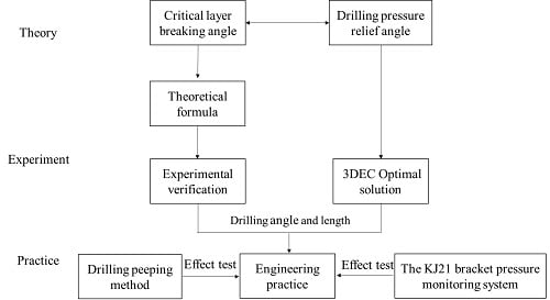
2. Materials and Methods

As a work surface pressure relief method, the drilling pressure relief method is widely used to deal with the problem that the hard top plate is difficult to fall, and the rock burst is strong. Figure 1 shows the “masonry beam structure” where Qian Minggao [21,22] proposed the roof to fall, where A is the coal wall support zone, B is the separation zone, and C is the re-compaction zone. The rock after the fracture of the rock formation is mutually extruded to form a horizontal force T, thereby generating a frictional force F between the rock layers. Any rock formation is subjected to the interaction of the overlying strata to generate loads q. The longitudinal fissure formed after the overburden strata breaks on the roof is gradually developed. If the elevation angle of the drilling relief hole is consistent with the fracture development direction (rock fracture angle α), the borehole blasting will increase the lateral space of the fracture and reduce the lateral space. The horizontal pressing force T increases the possibility of deformation instability; on the other hand, it reduces the strength and friction force F of the rock at the occlusal point of the rock mass, and the sliding force is greater than the friction force at the arch foot. The roof step is caused to sink, thereby achieving the purpose of pressure relief. Therefore, it is very important to determine the angle of elevation of the pressure relief drilling to improve the pressure relief effect.

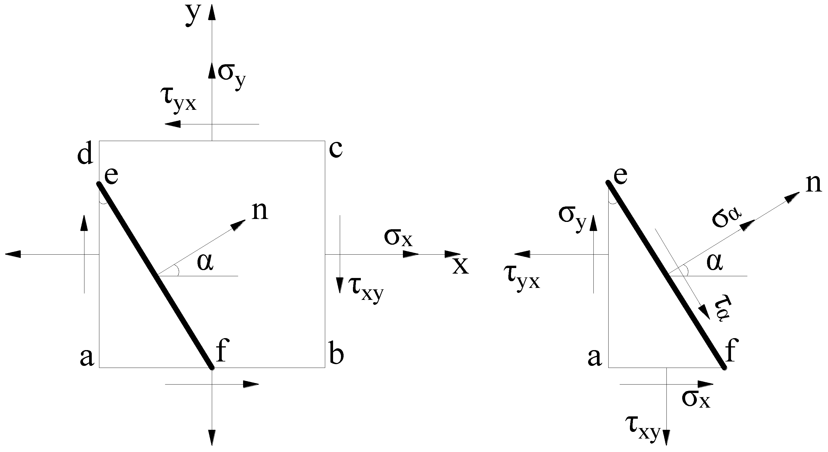
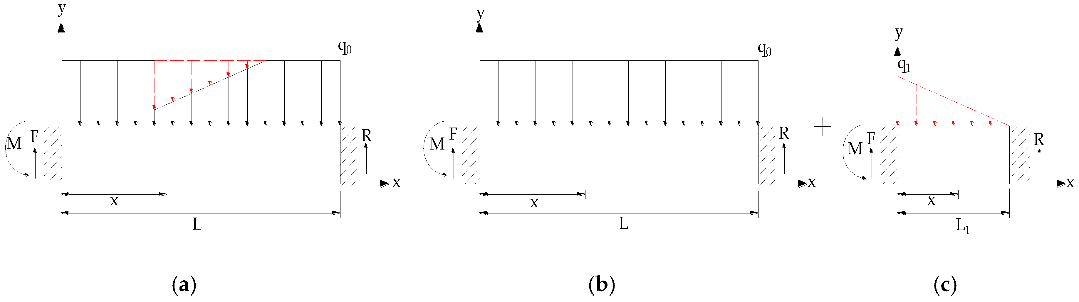
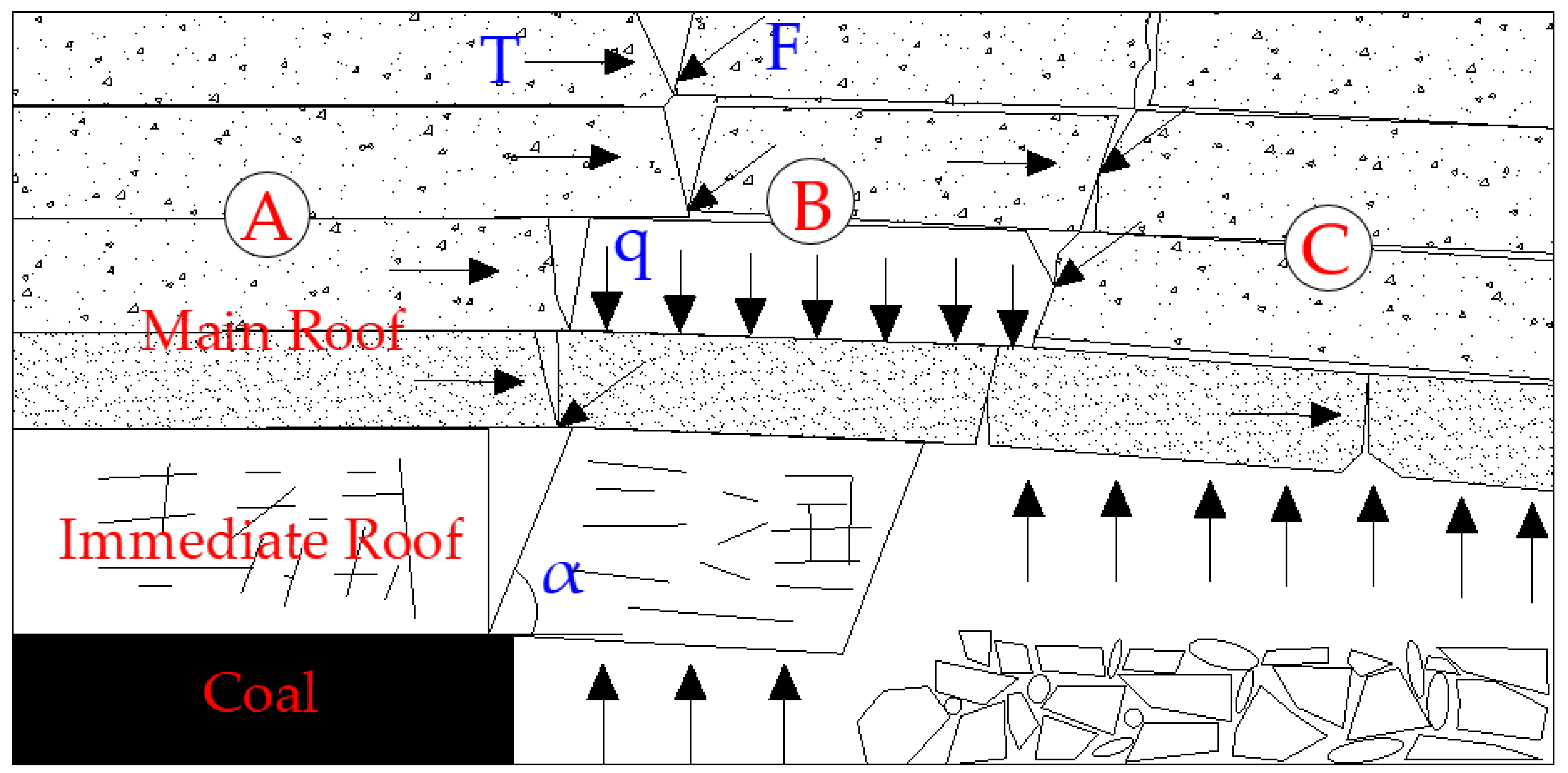
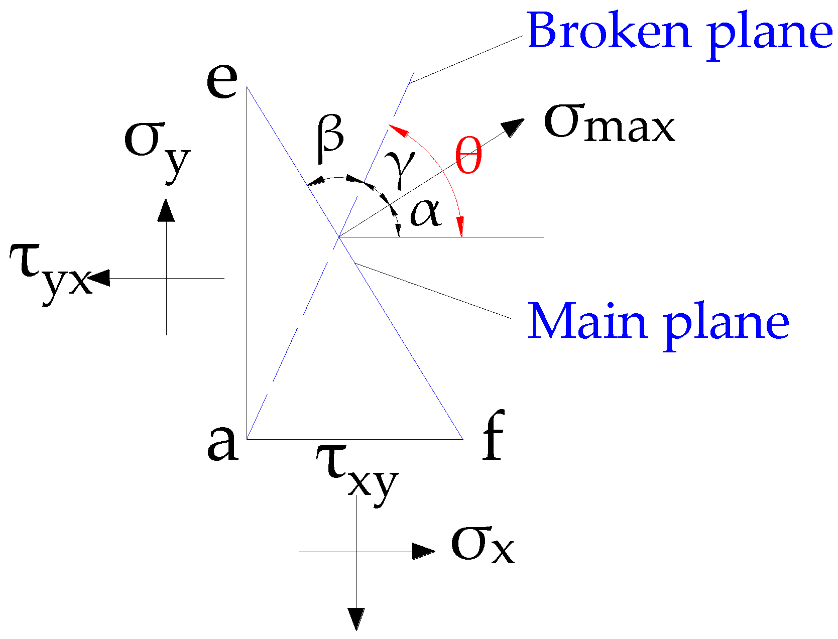
3. Derivation of Breaking Angle Mechanics of Key Layers under Repeated Mining

The breaking of the key layer is regarded as the break of the beam “O-X”, and the upper surface is affected by the uniform load q. According to the two-dimensional stress analytical method of material mechanics [23,24], the normal stress σ at any point in the beam is solved. The force of any unit in the key layer of the overlying rock is shown in Figure 2. In Figure 2, it is assumed that the stress components σx, σy, τxy, τyx are all known. According to the shear stress reciprocal theorem and the stress balance equation, it can be concluded that:
{ σ α = σ x + σ y 2 + σ x σ y 2 cos 2 α τ xy sin 2 α τ α = σ x + σ y 2 sin 2 α + τ xy cos 2 α .
Let σα in Equation (1) be derived from α:
d σ α d α = 2 ( σ x σ y 2 sin 2 α + τ xy cos 2 α ) .
If α = α0, Equation (2) can be made zero, and the normal stress takes the extreme value on the cross section determined by α0 (the beam is taken as the unit width). Substituting α0 into Equation (2) and making it equal to zero yields:
α 0 = 1 2 arctan 2 τ xy σ x σ y .
According to the stress decomposition amount of the key layer rock beam derived by Xu Bin [15], substituting into Equation (3), Equation (4) is obtained, where L is the key layer breaking distance and h is the key layer average thickness.
α 0 = 1 2 arctan 3 L h
The key layer is simplified to a simply supported beam, and the maximum normal stress σmax is used as the basis for rock fracture. When σmax = RT, the normal stress of the critical layer at this point reaches the tensile strength limit there, and the rock layer will be cracked there. The ultimate span when the beam is broken is:
L = 2 h 2 R T 3 q .
Substituting Equation (5) into Equation (4) yields:
α 0 = 1 2 arctan 6 2 R T 3 q .
Equation (6) is the formula for calculating the angle between the principal stress plane and the horizontal plane of any unit body of the key layer. It is only necessary to substitute the tensile strength limit RT of the key layer and the uniform load q above the key layer, according to Mohr–Coulomb. The criterion is that the key layer is in a state of extreme equilibrium when it is broken. At this time, the angle β′ between the fractured surface and the maximum normal stress σmax generated by the shear failure of the rock meets:
β = π 4 φ 2
where φ is the internal friction angle of the rock. The plane relationship between the broken section of the key layer and the horizontal plane is shown in Figure 3.
It can be seen from Figure 3 that the breaking angle of the key layer, that is, the angle between the broken section and the horizontal plane θ (breaking angle of the key layer) is:
θ = 1 2 arctan 6 2 R T 3 q + π 4 φ 2 .
When the working face adopts the down-mining method for coal mining, the lower working face is affected by repeated mining when it is mining below the goaf of the upper working face, and the main instability mode of the working face roof is changed from the original turning instability to the sliding instability. When the roof of the lower working face is broken, and the friction is coupled with the rock layer of the goaf, the assumption of the theoretical calculation of the breaking angle is no longer valid. As shown in Figure 4a, when the lower working face is pushed to the lower side of the upper goaf, the top plate of the working face is broken and affected by the broken rock in the goaf, and the original girder structure of the turning instability is transformed into the simply supported beam structure cut along the roof. As the upper goaf is not fully compacted, the hypothesis that the key layer is uniformly loaded is no longer valid. To simplify the analysis, the overlying strata are considered as simply-supported beam structures, and the red dotted line is regarded as the load reduction zone. The overlying rock stratum is regarded as a simple supported beam structure, and the formation law of the breaking line of the key layer is analyzed. Using the bending moment superposition of material mechanics, for the convenience of calculation, the mechanical model shown in Figure 4a is regarded as a simply-supported beam model without repeated mining in Figure 4b, and Figure 4c is reduced by repeated mining stress unloading. The simple supported beams are superimposed.
Figure 4b simplifies the key layer as a fixed beam, where the normal stress of the critical layer reaches the tensile strength limit at that point, where the rock layer will be cracked, and the key layer that is not subjected to repeated mining is broken. The angle calculation formula is Equation (8). The actual meaning of the model in Figure 4c is that the load on the working face is reduced by the effect of repeated mining when the working face is recovered to the goaf of the upper working face, partly because the top plate of the upper working face is crushed and relieved. The complete compaction of the goaf also results in a redistribution of the load. According to the equilibrium equation and the bending moment equation, the above simple bending beam bending moment formula is:
M ( x ) = q 1 l 6 x q 1 6 l x 3 .
In Formula (9), q1 is the maximum value of the pressure relief of the top plate due to the pressure relief. M(x) is determined by the derivative of M(x) and x is 0, and the maximum value and positive value of the bending moment M are solved. The maximum value of the stress σ is (takes a unit width of 1):
M max = 3 27 q 1 l 2 σ max = 2 3 q 1 l 2 9 h .
The maximum normal stress σmax is used as the basis for rock fracture. When σmax = RT, that is, the normal stress of the critical layer at this point reaches the tensile strength limit there, and the rock layer will be cracked there. The ultimate span when the beam is broken is:
L = 3 h 3 R T 6 q 1 .
According to the reduction of the load-breaking cross-section and the horizontal plane relationship, the calculation formula of the breaking angle of the key layer breaking caused by the reduced load under the repeated mining is:
θ = 1 2 arctan 9 3 R T 6 q 1 π 4 + φ 2
Calculate the breaking angle θ1 of the key layer caused by the assumed unrepeated uniform load according to Equation (8), and then calculate the breaking angle θ2 caused by the reduced load of the partial load indicated by the red dotted line according to Equation (12). The calculation of the breaking angle θ of the key layer caused by the mining effect is:
θ = θ 1 ( λ 1 ) θ 2
Substituting Equations (8) and (12) into Equation (13) yields:
θ = 1 2 arctan 6 2 R T 3 q 0 + π 4 φ 2 ( λ 1 ) [ 1 2 arctan 9 3 R T 6 q 1 π 4 + φ 2 ]
where RT is the ultimate tensile strength of the key layer, q0 is the uniform load on the key layer, q1 is the load reduced by repeated mining, and λ is the repeated disturbance coefficient. When λ = 1, Formula (14) represents the theoretical calculation formula for the breaking angle of the key layer of single coal seam; when λ = 2, Formula (14) represents the theoretical calculation formula of the breaking angle of the key layer affected by repeated mining in the short-distance double-coal mining.

4. Experimental Verification of Similar Materials for Breaking Angle Calculation Formula

The W1145 working face and the W1123 working face of the west wing of the first mining area of the Kuangou coal mine are mainly used for the B4-1 coal seam and the B2 coal seam. First, the upper W1145 working face is recovered. After the W1145 working face is finished and the overburden is stable, the lower W1123 working face is recovered. When the W1145 working face is recovered, the overburden layer on the roof can be regarded as a uniform load (λ = 1); when the W1123 working face is recovered, the working face is pushed to the lower side of the W1145 working face and is affected by repeated mining. The overlying load is redistributed, and the critical layer breaking can be regarded as the mechanical structure model shown in Figure 4a (λ = 2).
A similar simulation model was designed based on the W1145 and W1123 double working faces of the Kuangou Coal Mine. The experiment used a plane strain model frame with dimensions (length × width × height) = 5.0 × 0.3 × 1.5 m to determine the geometric similarity ratio (αL = LH/LM) of the simulation experiment, which was 1:200, and the model pavement size (long × width × height = 5.0 × 0.3 × 1.5 m), and a layer of iron brick was placed on the top instead of the unsimulated rock formation to apply a load to the model. According to the lithologic characteristics of the overburden strata of the B2 coal seam detected by the Z1201 borehole histogram of the W1123 working face in the main study of the Kuangou coal mine, the load of each layer of the rock layer on the old roof was calculated layer by layer. The position of the key layer was judged, as shown in Table 1. The design and construction of the dynamic regulation of the overburden structure and the physical similarity simulation experiment provide support. The mining plan for the working face of the model is to move the W1145 and W1123 working faces to the model. According to the actual mining sequence of the mining face, firstly, the upper W1145 working face was recovered, and the cut hole was opened at 230 cm from the left boundary of the model B4-1 coal seam (8 cm), starting to recover the working face, mining to 30 cm away from the right boundary to stop mining, a total of 240 cm; in the model B4-1 coal seam W1145 working face mining end and overburden collapse stability, back to the lower W1123 working face in model B2. The coal seam was opened 38 cm from the left boundary and began to be harvested. When the mining was 30 cm away from the right boundary, the mining was stopped, and a total of 432 m was advanced.
In addition to its own weight, the load applied to any rock in the overburden is also affected by the interaction of the overlying strata. Assuming that the rock layer load q is evenly distributed, there are a total of m layers of rock layers directly above the top, each rock layer has a thickness of hi (i = 1, 2, …, m), and the volume force is γi (i = 1, 2, …, m), and elasticity Modulus Ei (i = 1, 2, …, m). The rock layer controlled by the first layer has n layers. The first layer of rock and the n layer will be simultaneously deformed to form a composite beam. According to the theory of the overburden composite rock beam, the first layer can be obtained by the load that the n layer affects [25]:
( q n ) 1 = E 1 h 1 3 i = 1 n h i γ i / i = 1 n E i h i 3
where (qn)1 refers to the load above the hard rock layer of the first layer; γi, hi, Ei refer to the bulk density, thickness, and elastic modulus of the i-th layer, respectively, i = (i = 1, 2, …, n). The load q of each layer is calculated according to Formula (15). The results are shown in Table 1.

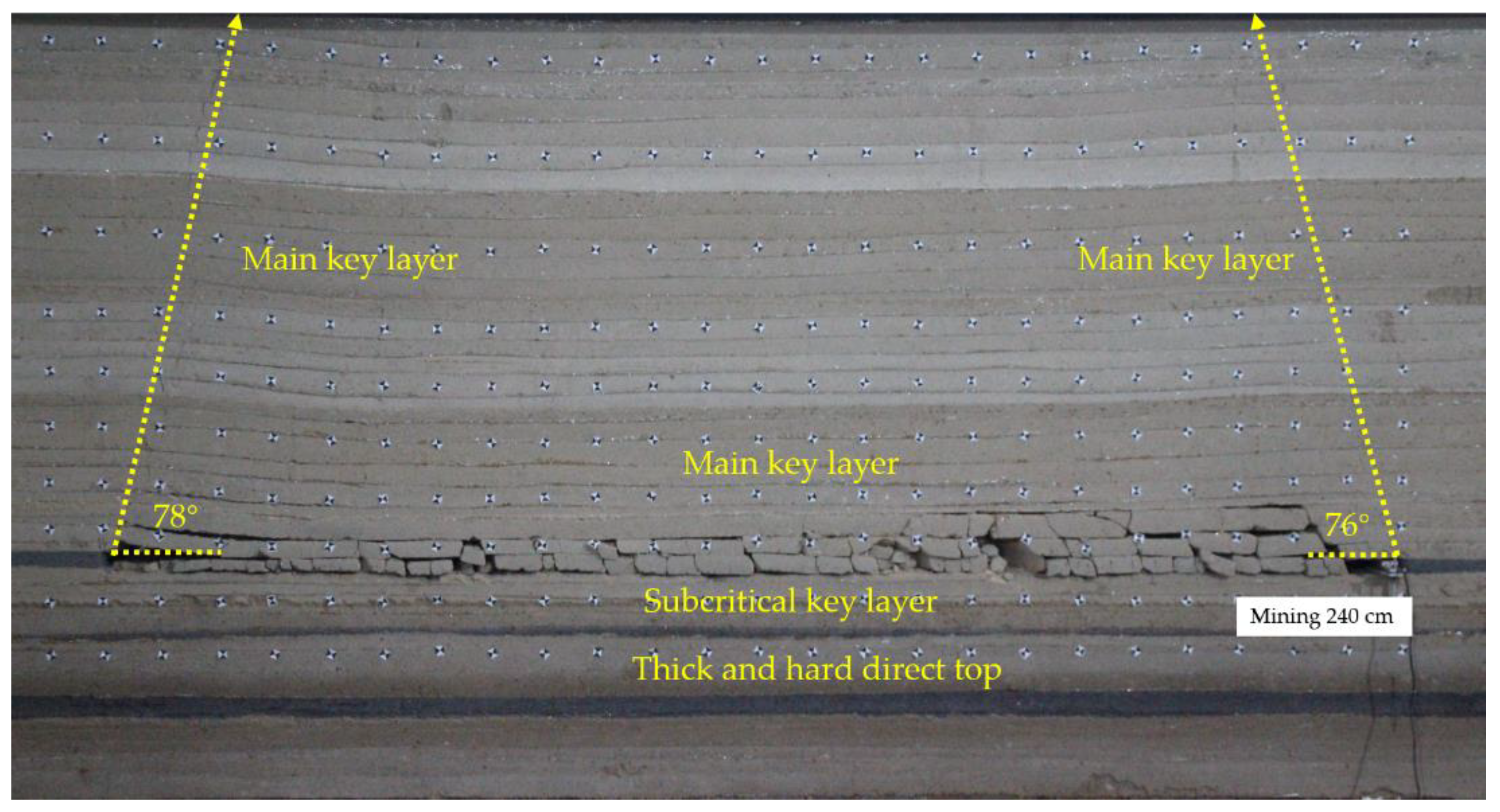
4.1. Verification of Breaking Angle of Key Layer in Single Coal Seam

The wide trench coal mine adopts the method of down mining to carry out mining. When the W1145 working face is recovered, it is not affected by repeated disturbances. Therefore, λ = 1 can be used to calculate the breaking angle of the key layer of the W1145 working face. The mechanical parameters of the double key layer rock are substituted into Formula (14). The main key layer parameters are a compressive strength of 7.58 MPa, uniform load of 0.41 MPa, and internal friction angle of 22°. Subcritical parameters are a compressive strength of 5.31 MPa, the cloth load is 0.36 MPa, and the internal friction angle is 20°. The calculated primary bond layer breaking angle is 77.64°, and the subcritical layer breaking angle is 78.47°. Figure 5 shows the collapse morphology of the overburden after the end of the W1145 working face. Because the overburden of the W1145 working face is only affected by the uniform load above the top surface of the working face, the measured breaking angle range is 76–78°. The results for the theoretical calculation are basically consistent, and the applicability of the theoretical formula of breaking angle in a single working face is verified.

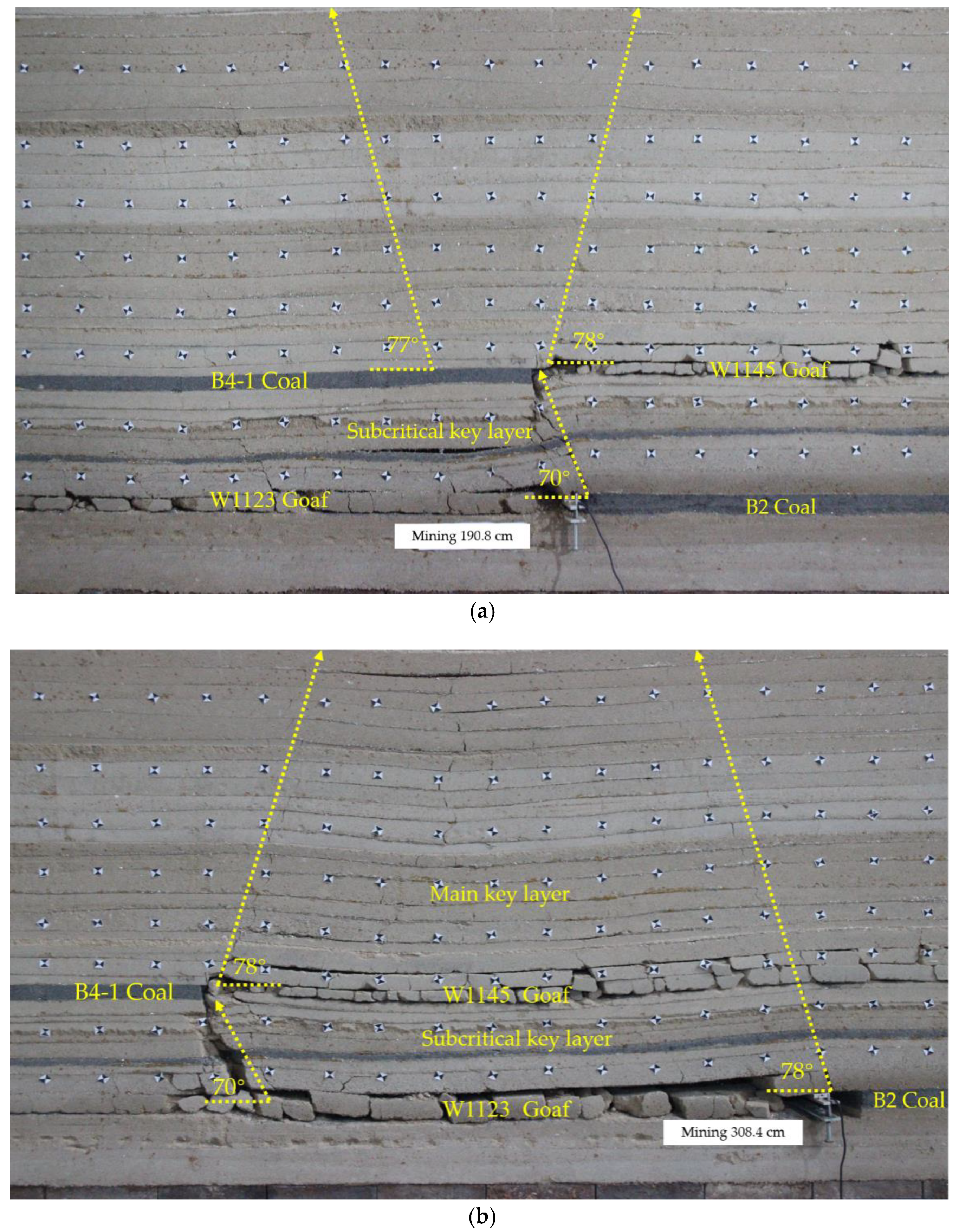
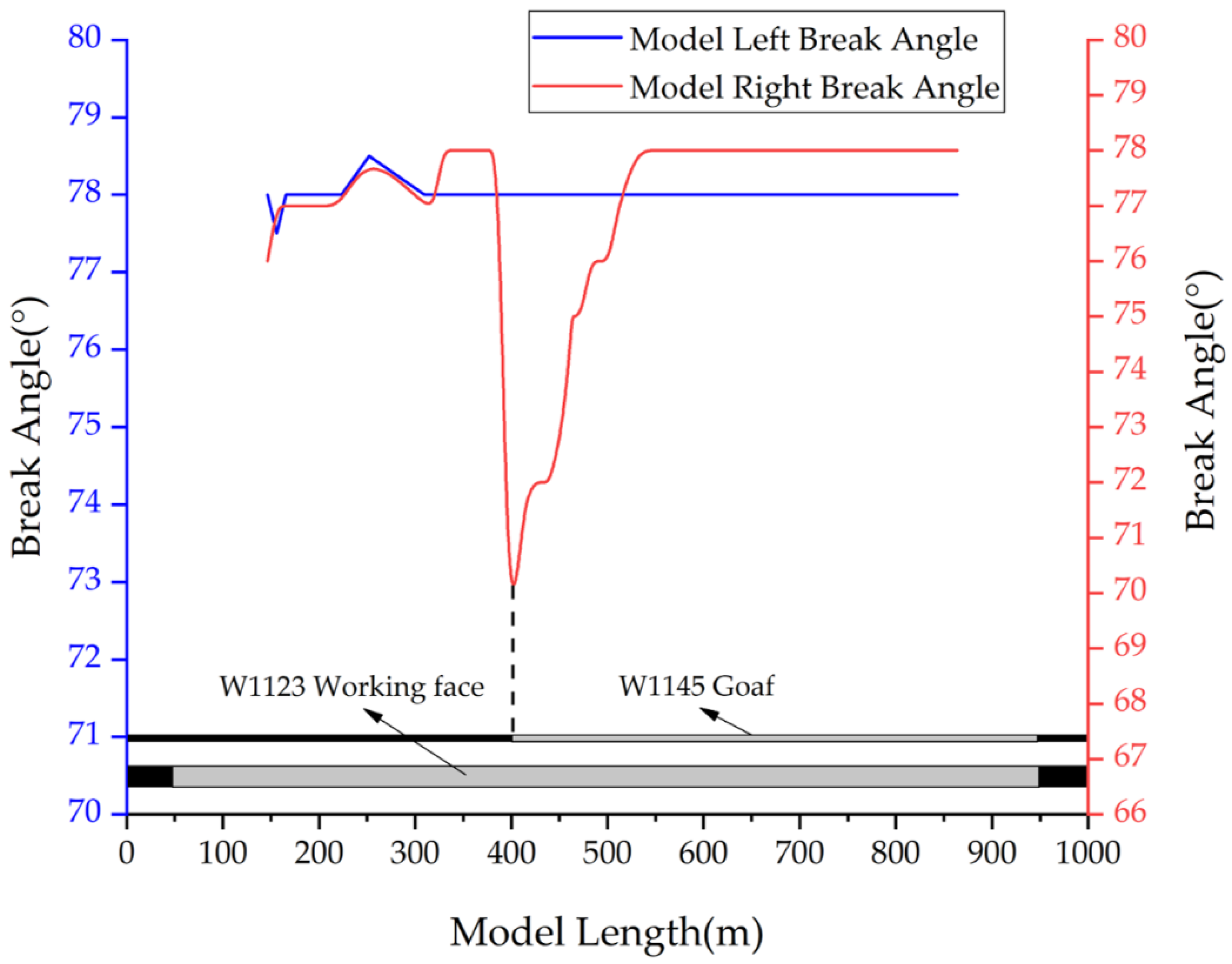
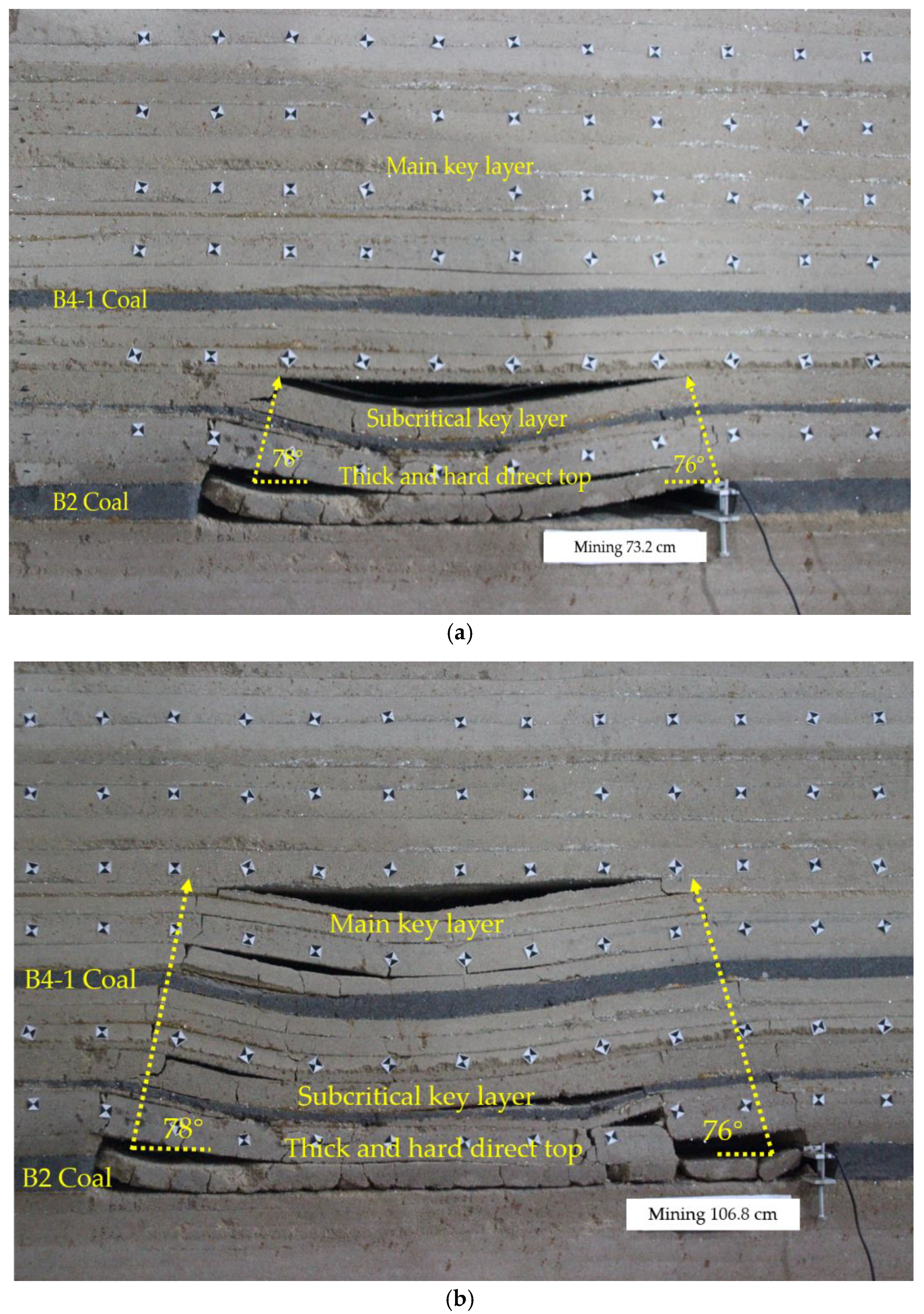
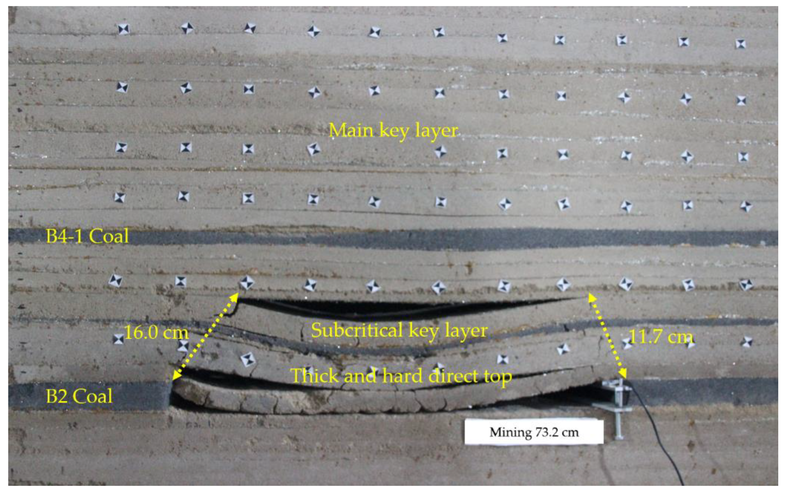
4.2. Key Layer Breaking Angle Verification under Repeated Mining

When mining the W1123 working face, take λ = 2 when calculating the breaking angle of the key layer of the W1123 working face considering the influence of repeated disturbance. The compressive strength of the sub-critical layer rock mechanics parameters is 5.31 MPa, the uniform load is 0.36 MPa, the load is reduced by 0.30 MPa, and the internal friction angle is 20°; the compressive strength of the main key layer rock mechanics is 7.58 MPa, and the uniform load is 0.41 MPa. The breaking angle of the sub-critical layer calculated by substituting (14) is 69.88°, and the breaking angle of the main key layer is 69.82°. When the W1123 working surface is advanced to 73.2 cm, the sub-critical layer collapse characteristics are as shown in Figure 6a. The left side of the model has a breaking angle of 78°, and the right side of the model has a breaking angle of 76°. When the W1123 working surface is advanced to 106.8 cm, the main key layer collapse is as shown in Figure 6b; the left side of the model break angle is 78°, and the right side of the model angle is 76°. The difference between the measured results and the theoretical calculation results is large, which indicates that the λ = 2 is not applicable when the W1123 working face is firstly collapsed, because when the W1123 working face is recovered to 106.8 cm, it is far away from the W1145 working face, and it is less affected by repeated mining. At this time, the initial collapse of the double key layer of the W1123 working face is still applicable to the case where the single coal seam is not subjected to repeated mining (λ = 1), and when the λ = 1, the physical parameters of the double key layer are substituted into Formula (14). The theoretical range of the breaking angle of the double key layer is 77–78.5°, which is basically consistent with the measured results. The rationality and applicability of the theoretical formula of the breaking angle of the key layer of the single coal seam are verified again.
As shown in Figure 7a, when the W1123 working face is 190.8 cm, it is directly below the W1145 open-cut eye, and the right side of the model formed by the influence of repeated mining is 70°, and when λ = 2 (14), the calculated 69.8° is basically consistent, which verifies the accuracy and applicability of the theoretical formula of the breaking angle of the key layer under repeated mining. As shown in Figure 7b, when the W1123 working face is recovered to 308.4 cm, the fracture line on the right side of the W1123 working face and the breaking line above the W1145 goaf are connected, because the goaf is re-compacted by the overlying fractured rock. The formation of the key layer breaking line is no longer affected by the repeated mining effect, and the resulting breaking angle is increased to 78°.
The W1123 working face is self-opening and cutting to the breaking angle on both sides of the working face end model, and the resulting breaking angle is shown in Figure 8. It can be seen from Figure 8 that when the W1123 is recovered to the right side of the W1145 goaf model, the breaking angle suddenly drops to 70°, and as the working surface continues to advance to 308.4 cm, the right side breaking angle of the model rises to 78°. Because the broken line on the left side of the model tends to be stable and is less affected by the mining of the working face, and the breaking angle on the left side of the model is basically unchanged. When the broken line on the right side of the model and the overburden fracture are connected, the broken lines on both sides of the model are basically not affected by the W1145 goaf, and the breaking angle is 78°, which is consistent with the theoretical calculation results.

5. Simulation Analysis of Influence of Elevation Angle of Hard Roof Pressure Relief Drilling on Pressure Relief Effect

5.1. Numerical Model Construction and Calculation Parameters of Pressure Relief Drilling Elevation Angle

In order to determine the collapse morphology and pressure relief effect of the overlying strata on the working face under different pressure relief drillings, the 3DEC numerical simulation was used to simulate the fracture morphology and stress change trend of the overburden after the pressure relief of the borehole. Taking the W1123 working face of Kuangou Coal Mine as the engineering background, the unloading pressure and the different pressure relief angles of 73°, 78°, and 83° were designed to observe the overburden collapse and stress distribution, so as to verify the reliability of the theoretical calculation results.
The basic principle of 3DEC is based on Newton’s second law. It is assumed that the rock blocks cut by the joint fissures are rigid bodies, and the rock masses are arranged in a mosaic according to the joint fissures of the whole rock mass. Each rock block has its own position and is in equilibrium in the space. When the external force or displacement constraint changes, the block will be displaced under the action of its own weight and external force, then the spatial position of the block will change, which in turn will cause the force and position of the adjacent block to change, even the blocks overlap each other. As the external force or constraint changes or the continuation of time, more blocks change and overlap each other, simulating the movement and rotation of each block until the rock mass is destroyed. In 3DEC, the contact friction type joint was used to simulate the contact relationship, and the Coulomb slip model was often used. The Mohr–Coulomb formula was also used for the shear strength of the structural plane of this experiment.
τ = σ tan φ + c
In Formula (16), c and φ are the cohesive force and friction angle of the structural plane, σ is the normal stress of the structural plane, and τ is the shear strength value of the surface of the structural plane. Using 3DEC to simulate the actual overburden condition of the Kuangou coal mine, the rock layers with different lithologies in Table 1 were given different mechanical parameters to ensure that the gravity and external force of each layer were consistent with the actual conditions. The detailed parameters are shown in Table 2.

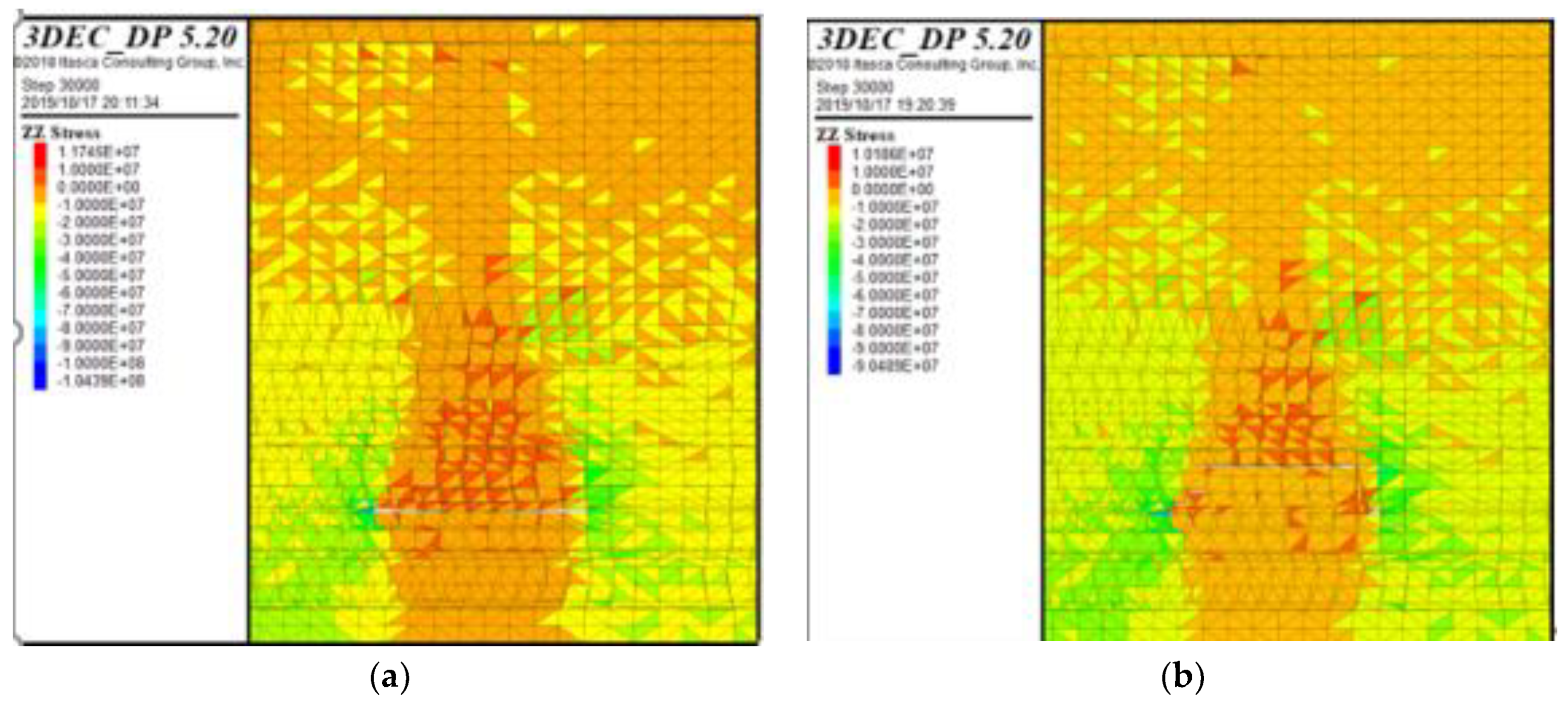
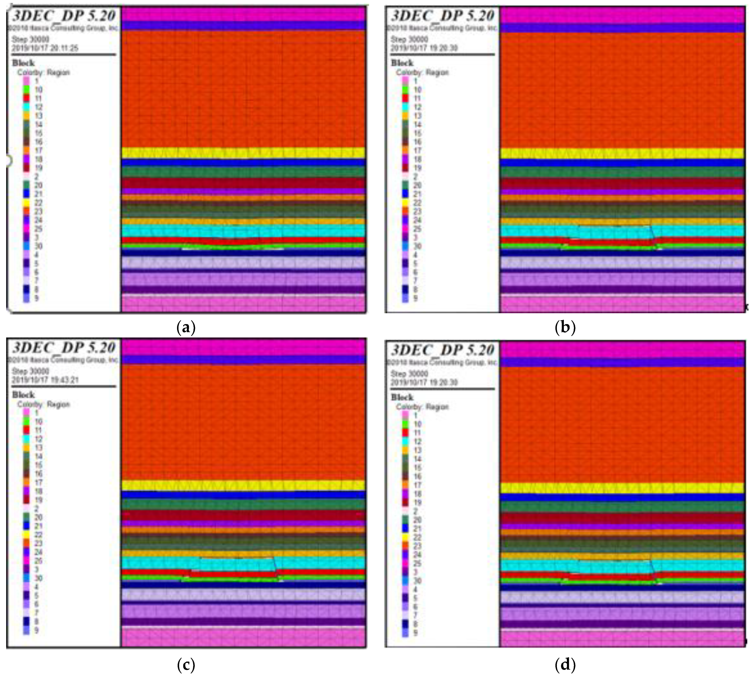
5.2. Falling Form of Roof When Different Pressure Relief Drillings Are at Elevation Angle

With W1123 working face mining as the engineering background, the top plate of the working face is difficult to fall due to the hard top plate. In order to compare the pressure relief effects of different pressure relief angles, the three unloading pressures of 73°, 78°, and 83° were respectively designed. The four cases of the corner are shown in Figure 9. It can be seen from the figure that when the working face is not equipped with pressure relief drilling, the vertical roof is cracked and the rock layer is not broken; the different pressure relief holes can be arranged to observe that the roof is falling, and the crack development is basically the same, only the covering The rock falling condition cannot judge the pressure relief effect of different pressure relief angles, so the pressure relief effect should be judged from the vertical stress change of the pressure relief after the different pressure relief angles are arranged. In order to highlight the effect of the drilling pressure relief, only partial models are shown in Figure 9 and Figure 10.

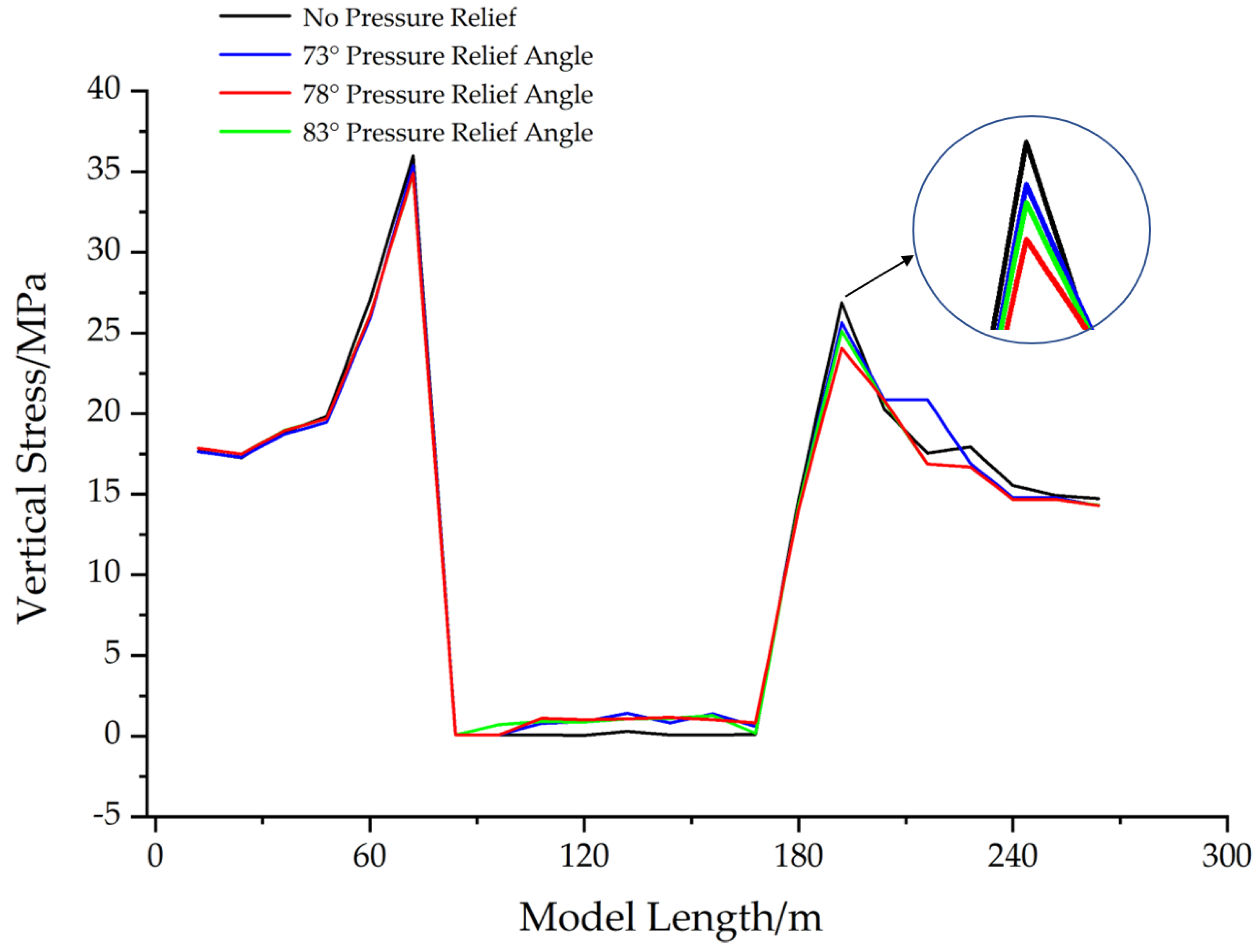
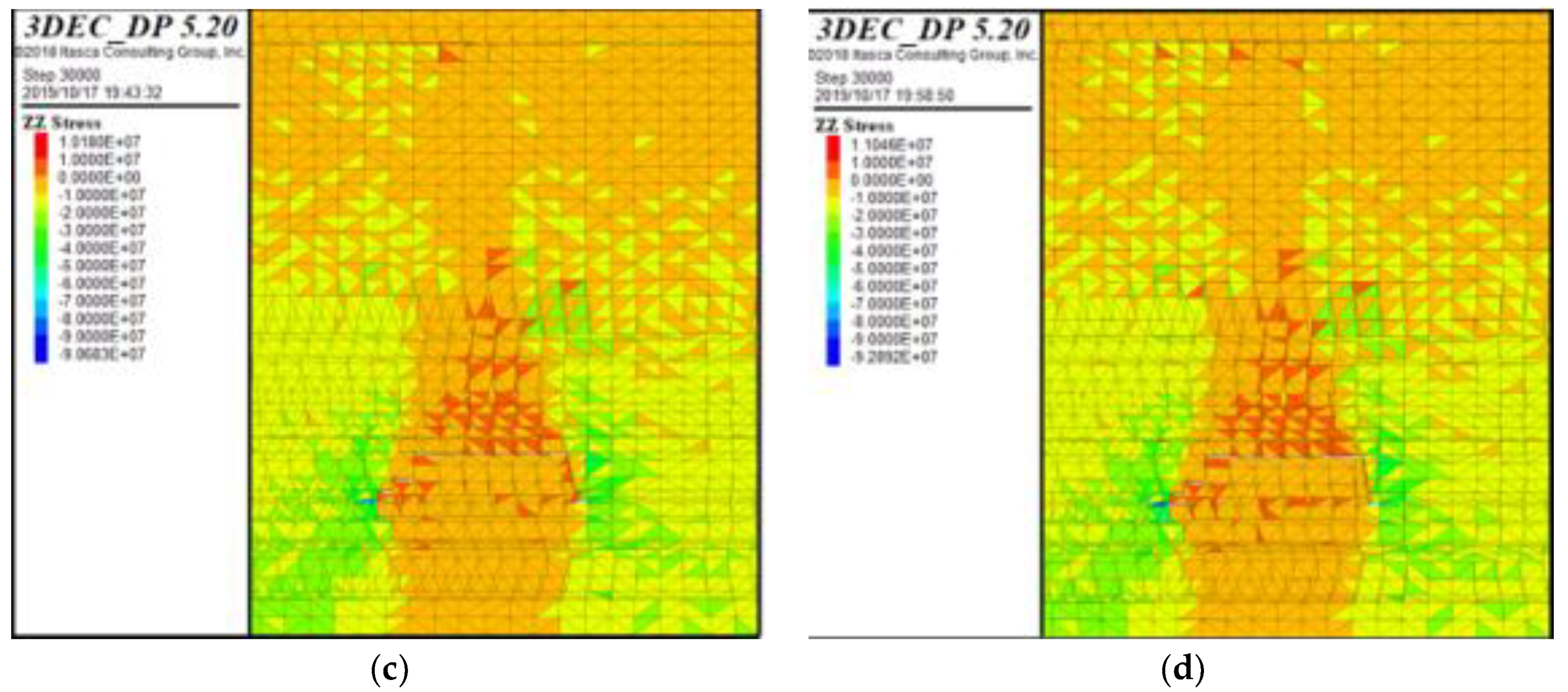
5.3. Stress Distribution Law of Different Pressure Relief Drillings at Elevation Angle

The vertical stress distribution maps of the four different unloading pressures and the three different pressure relief angles of 73°, 78°, and 83° are respectively derived by using 3DEC, as shown in Figure 10. It can be seen from the figure that when the pressure relief angle is 78°, the vertical stress reduction is the largest, and the pressure relief effect is the best.
Figure 11 records the vertical stress of the model from 0 to 300 m. The first peak of the stress map is located in the stress concentration zone at the open cut. The peak is basically the same. The second peak indicates the vertical after the overburden. It can be seen that the vertical stress is significantly reduced after the pressure relief drilling is arranged compared to the unloading pressure, wherein the vertical stress is reduced by 1.0 MPa compared to the unloading pressure when the pressure relief angle is 73°, and the pressure relief angle is 83°. When the pressure is 78°, the vertical stress is reduced by 1.2 MPa. When the pressure relief angle is 78°, the vertical stress is reduced by 4.0 MPa compared with the unloading pressure. Therefore, it can be seen that when the pressure relief angle is 78°, the pressure relief effect is the best, and the theoretical calculation results are consistent, which verifies the reliability of the theoretical formula.

6. Application of Pressure Relief Drilling in Engineering Practice

6.1. Kuangou Coal Mine Engineering Background

The hard top has physical and mechanical properties such as high hardness, high strength, good compactness, large delamination thickness, and low degree of development of joint fissures. After the working face is pushed forward, the roof is difficult to fall naturally, and the goaf is not completely filled, causing some of the roof to suspend the roof and form a cantilever beam structure. The gravity of the overlying rock acts on the surrounding rock of the roadway, resulting in serious deformation of the surrounding rock of the roadway. When the earthquake or earthquake induces vibration, it is easy for rock to burst, causing serious casualties and economic losses, which poses a great safety hazard to the safe and efficient mining of the working face. Therefore, in order to maintain the stability of the surrounding rock of the roadway and ensure the safe and efficient recovery of the working face, it is necessary to avoid the stress concentration of the surrounding rock caused by the hard roof [26,27,28,29,30,31,32]. The drilling pressure relief technology can reduce the internal stress concentration of the coal seam in the roadway, reduce the range of the high stress area, increase the caving property of the roof, and transfer the stress peak inside the coal body to the deep part to reduce the deformation of the surrounding rock of the roadway. Figure 12 is a photo of an accident caused by rock burst at the working face of the Kuangou coal mine.

6.2. Effect of Scale Effect on Drilling Length

It can be seen from Figure 13 that when the W1123 working face is recovered to 73.2 cm, the sub-critical layer is initially degraded, and the length of the fracture line of the rock layer is 11.7–16.0 cm. The geometric similarity ratio between the similar simulation experiment and the actual field experiment is 1:200, and it can then be inferred that the actual drilling length of the field should be 23.4–32 m. The 3DEC numerical simulation experiment has a drilling length of 28 m, and the numerical similarity between numerical simulation and field engineering practice is 1:1. Considering the influence of scale effect on the design of borehole length, combined with the thickness of the top surface of the working face, the length of the working face, the dip angle of the coal seam, the distance between the bottom of the hole, and the distance of the orifice, the final length of the borehole is 30 m.

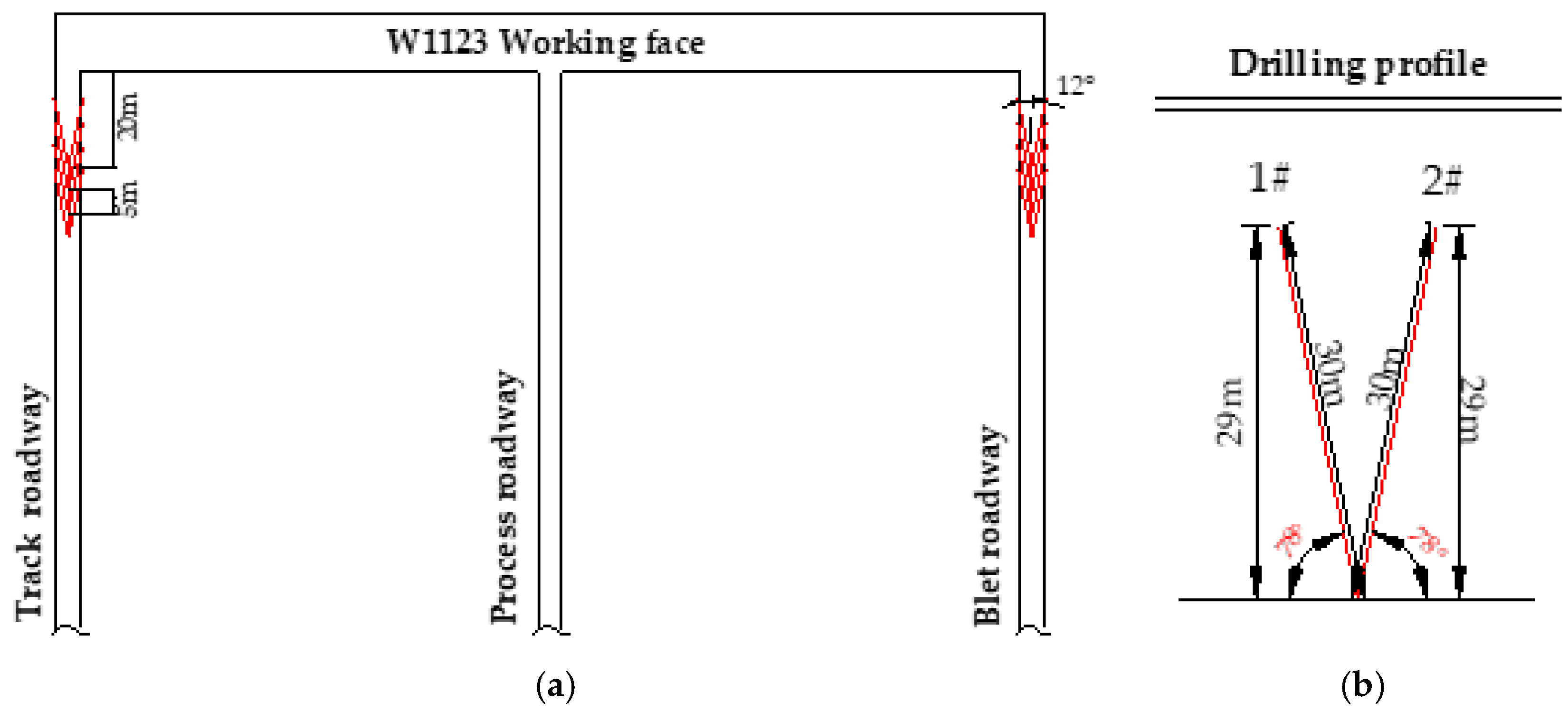
6.3. Design of Pressure Relief Drilling Parameters for Working Face

Before the mining of the W1123 working face, the theoretical analysis of the elevation angle of the pressure relief drilling, the similar simulation experiment, and the numerical simulation experiment were completed, and the reasonable angle of the top drilling was determined, and the experiment was directly carried out in the field. In order to ensure that the working face meets the mining with the top plate during normal mining, avoiding the long tailway leading to the release of the elastic energy of the roof in time, the front end of the working face is pre-cracked and relieved. According to the actual engineering conditions that the hard roof of the W1145 and W1123 working face of Kuangou Coal Mine is difficult to fall, combined with the theoretical calculation results and numerical simulation results of the breaking angle of the key layer, the breaking angle of the key layer was used as the basis for designing the elevation angle of the preloading pressure relief hole. Figure 14 is a schematic diagram of the pre-pressure relief drilling arrangement of the W1123 working face. The drilling design elevation angle is 78°. The ZDY1900 drilling rig model and the supporting drill pipe are used for the upper and lower grooves. The blasthole starts construction 30 m away from the working face (the opening area is 30 m in the initial area), each 10 m group of blastholes, the hole depth is 30 m, and the blasthole is arranged perpendicular to the center of the roadway line. The hole is sealed with loess and cement anchoring agent. The length of the sealing hole is 10 m, the average charge of the blasthole is 50 kg, and the length of the charge is 20 m.

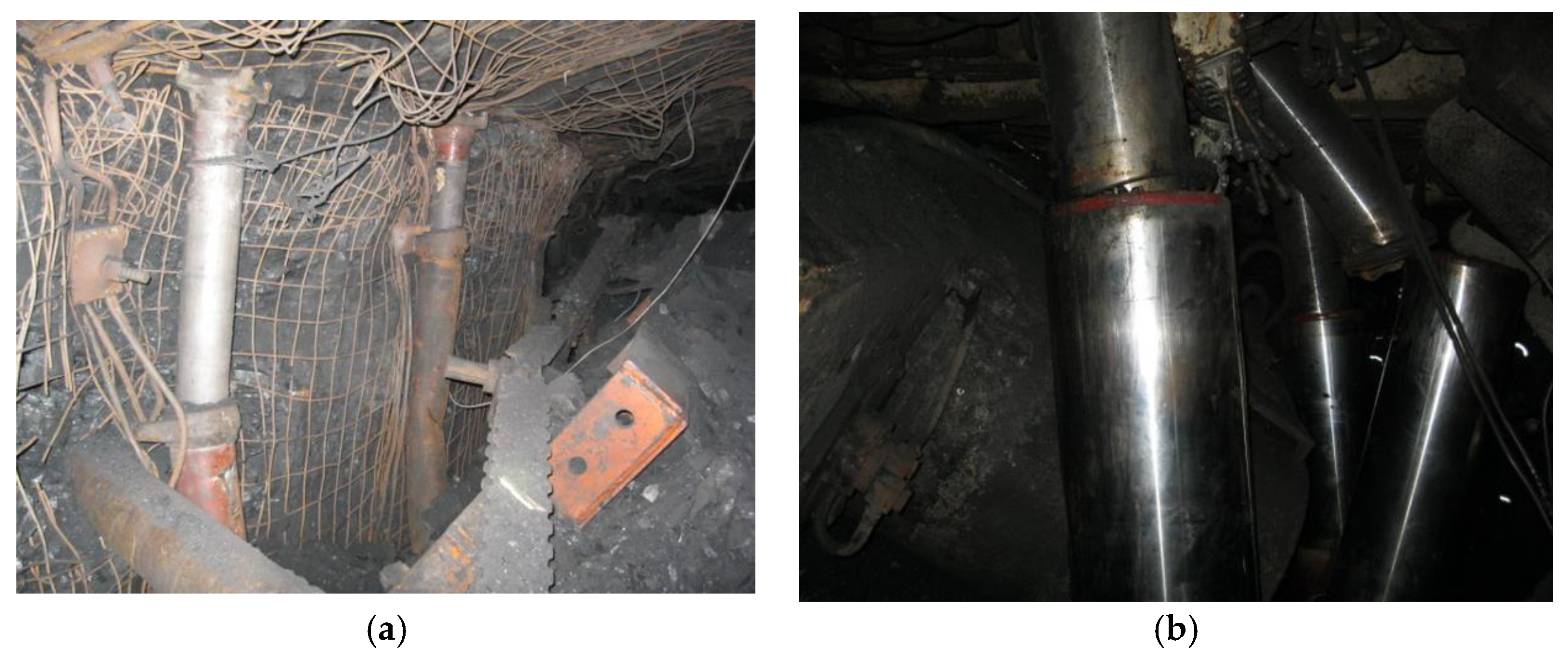
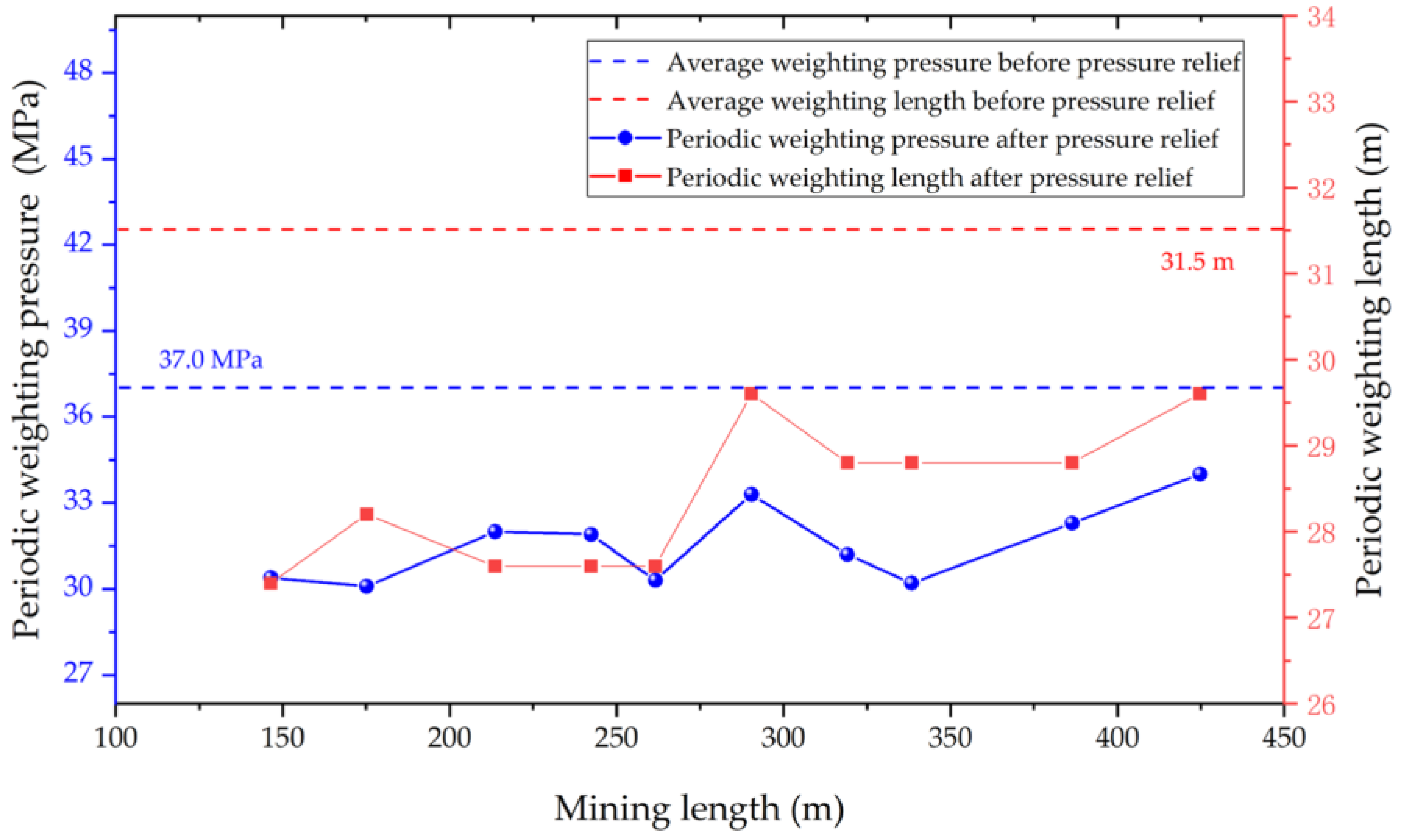
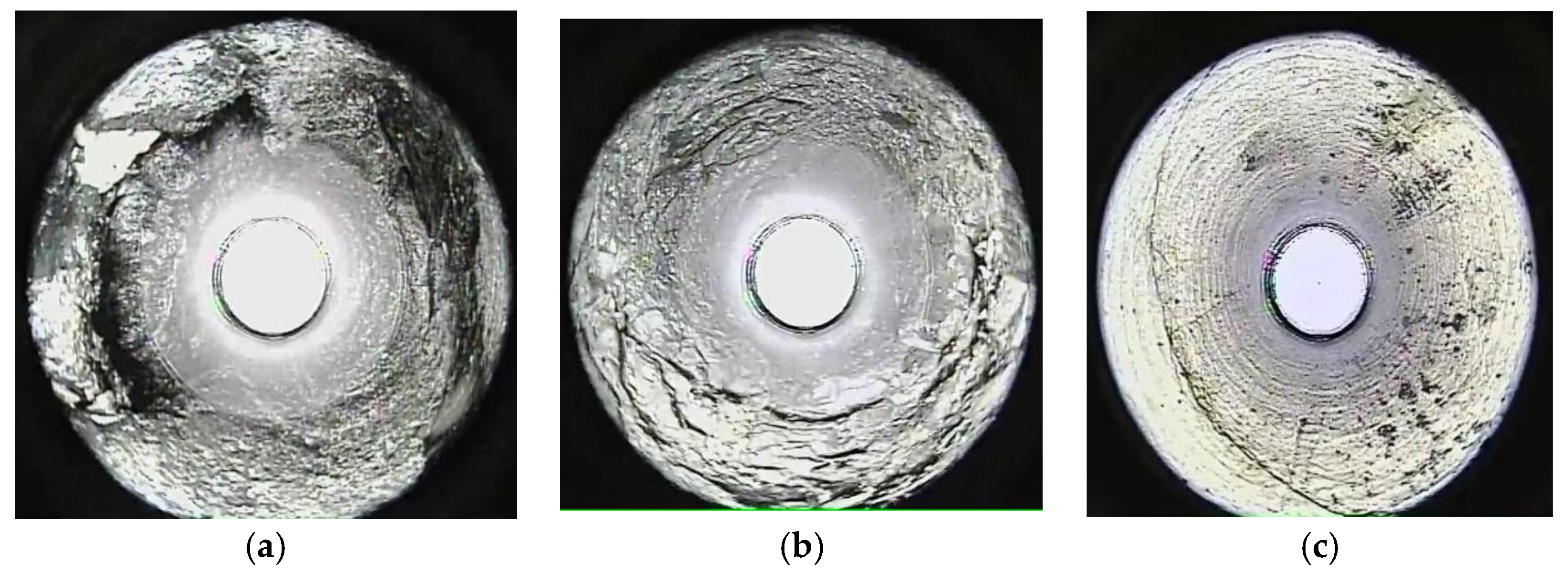
6.4. Pressure Relief Effect Test

The drilling peeping method was used to observe the collapse of the roof cycle. The observation results are shown in Figure 15. The 1–8 m coal seam crack is completely developed above the working face, and the hole wall is broken. The 9–20 m roof crack is fully developed and the hole wall is broken. The cracks in the top plate of 10–30 m are relatively developed, and the cracks are crisscrossed. It can be clearly seen from the peeping screenshot that the cracks in the roof of the working face are obvious in the 30 m range, especially the roof cracks within 20 m range are completely developed, and the roof is broken; in the area above 20 m, the vertical and horizontal cracks of the roof are obviously staggered, and the cracks are large and local. The roof of the area is also broken. It can be seen that the initial drilling and blasting has achieved the purpose of destroying the roof. It can be considered that the roof can be self-degraded during the propulsion process.
Figure 16 shows the initial pressure of the W1123 working face in Kuangou Coal Mine. The KJ21 bracket pressure monitoring system is used to monitor the change of the support pressure of the working face when the old top is broken, and the average weighted resistance is used to analyze the initial pressure step of the working face. It can be seen from the figure that the average weighting pressure before pressure relief is 37.0 MPa, and the average weighting length is 31.5 m; the average periodic weighting pressure after pressure relief is 31.6 MPa, and the average periodic weighting length pressure after pressure relief is 28.4 m. From the average periodic weighting pressure and length analysis, the average periodic weighting pressure decreased by 5.4 MPa, and the average periodic weighting length decreased by 3.1 m, indicating that the pressure relief effect was good.

7. Conclusions

(1) Based on rock mechanics and material mechanics, the theoretical formula of the double critical layer breaking angle of the double working face was derived, and the repeated disturbance coefficient λ was proposed. When calculating the breaking angle of the key layer of a single coal seam, take λ = 1; calculate λ = 2 when calculating the breaking angle of the key layer affected by repeated mining in the short-distance double-coal mining.
(2) When the W1145 working face was recovered, the breaking angle of the key layer of the model was basically the same as that of the key layer of the single coal seam; when the W1123 working face was not advanced to the W1145 goaf, and the W1123 working face was fully harvested. In the future, the calculation result of the theoretical formula of the double-key breaking angle of the single working face and the measured result of the model should have less error. When the W1123 working face was plucked below the W1145 goaf, it was affected by the repeated mining, according to the breaking under the repeated mining. The results calculated by the angular theory formula were basically consistent with the experimental simulation results. The above shows the rationality and reliability of the formula for the double-key layer breaking angle of the double working face.
(3) According to the theoretical analysis and numerical simulation results, a pressure relief bore with an elevation angle of 78° was arranged on the working surface, and the pressure relief effect was tested by the borehole peep method. According to the analysis of the drilling peep results, the breaking angle of the key layer calculated according to the formula could be used as the theoretical basis for the elevation angle of the relief hole. It is indicated that the theoretical formula of the breaking angle of the key layer is well applied to the practice of pre-cracking and pressure relief in the roof of the working face of the wide trench coal mine.

Author Contributions

F.C. conceived, designed, and analyzed the test results; T.Z. performed the experiments and wrote the manuscript. X.L. supervised the research work. All the authors revised and proofread the manuscript.

Funding

This work was sponsored by the National Natural Science Foundation of China (No. 51874231, 51504184), which is part of the Shaanxi Natural Science Fundamental Research Program Enterprise United Fund (2019JLZ-04). The “Special Support Program” of Shanxi Province in 2017 and Shaanxi Innovation Team Program (No. 2018TD-038) are gratefully acknowledged. The authors wish to acknowledge the financial supports of Outstanding Youth Science Fund of Xi’an University of Science and Technology (2019YQ2-16).

Acknowledgments

The author sincerely thanks for the equipment and site support provided by Key Laboratory of Western Mines and Hazard Prevention of China Ministry of Education and Key Laboratory of Coal Resource Exploration and Comprehensive Utilization, and also the fund support provided by the above funding for this work. Finally, the author sincerely thanks the Kuangou Coal Mine for their help and support in the field monitoring.

Conflicts of Interest

The authors declare no conflict of interest.

References

  1. Chen, Y.G.; Qian, M.G. Strata Control Around Coal Face in China; China University of Mining and Technology Press: Xuzhou, China, 1994; pp. 137–143. [Google Scholar]
  2. Düzgün, H.S.B. Analysis of roof fall hazards and risk assessment for Zonguldak coal basin underground mines. Int. J. Coal Geol. 2005, 64, 104–115. [Google Scholar] [CrossRef]
  3. Kong, P.; Jiang, L.; Shu, J.; Wang, L. Mining Stress Distribution and Fault-Slip Behavior: A Case Study of Fault-Influenced Longwall Coal Mining. Energies 2019, 12, 2494. [Google Scholar] [CrossRef]
  4. Wang, G.F.; Gong, S.Y.; Dou, L.M.; Cai, W.; Yuan, X.Y.; Fan, C.J. Rockburst mechanism and control in coalseam with both syncline and hard strata. Saf. Sci. 2019, 115, 320–328. [Google Scholar] [CrossRef]
  5. Kong, P.; Jiang, L.H.; Jiang, J.Q.; Wu, Y.N.; Chen, L.J.; Ning, J.G. Numerical Analysis of Roadway Rock-Burst Hazard under Superposed Dynamic and Static Loads. Energies 2019, 12, 3761. [Google Scholar] [CrossRef]
  6. Skrzypkowski, K. Compressibility of materials and backfilling mixtures with addition of solid wastes from flue-gas treatment and fly ashes. E3S Web Conf. 2018, 71, 7. [Google Scholar] [CrossRef]
  7. Skrzypkowski, K.; Korzeniowski, W.; Poborska-Mlynarska, K. Binding capability of ashes and dusts from municipal solid waste incineration with salt brine and geotechnical parameters of the cemented samples. Arch. Min. Sci. 2018, 63, 903–918. [Google Scholar]
  8. Brodny, J. Tests of friction joints in mining yielding supports under dynamic load. Arch. Min. Sci. 2011, 56, 303–318. [Google Scholar]
  9. Brodny, J. Determining the working characteristic of a friction joint in a yielding support. Arch. Min. Sci. 2010, 55, 733–746. [Google Scholar]
  10. Li, S.B. Borehole Drilling and Pressure Releasing Technology Applied to Mining Gateway Support in Three Soft Seam. Coal Sci. Technol. 2012, 40, 29–32. [Google Scholar]
  11. Gao, M.S.; Zhang, N.; Guo, C.S.; Dou, L.M. Mechanics and practice of combined supporting technology of 3D anchor-cable and unloading technology of wall of roadway. Chin. J. Geotech. Eng. 2005, 27, 587–590. [Google Scholar]
  12. Liu, H.G.; He, Y.N.; Xu, J.H.; Han, L.J. Numerical simulation and industrial test of boreholes destressing technology in deep coal tunnel. J. China Coal Soc. 2007, 32, 29–32. [Google Scholar]
  13. Xie, S.R.; Chen, D.D.; Sun, Y.D. Analysis on thin plate model of basic roof at elastic foundation boundary (I): First breaking. J. China Coal Soc. 2016, 41, 1360–1368. [Google Scholar]
  14. Moon, J.S. Representativeness of jointed rock mass hydraulic conductivity obtained from packer tests for tunnel inflow rate estimate. Int. J. Rock Mech. Min. Sci. 2011, 48, 836–844. [Google Scholar] [CrossRef]
  15. Xu, B.; Jiang, J.Q.; Dai, J.; Zheng, P.Q. Mechanical derivation and experimental simulation of breaking angle of key strata in overlying strata. J. China Coal Soc. 2018, 43, 299–606. [Google Scholar]
  16. Yang, P.J.; He, Y.; Guo, W.B. Disaster-causing mechanism and control measures of extremely thick and hard magmatic rock above working face. J. China Coal Soc. 2013, 38, 2106–2112. [Google Scholar]
  17. Wang, J.; Ning, J.G.; Qiu, P.Q.; Yang, S.; Shang, H.F. Microseismic monitoring and its precursory parameter of hard roof collapse in longwall faces: A case study. Geomech. Eng. 2019, 17, 375–383. [Google Scholar]
  18. Sainoki, A.; Mitri, H.S. Simulating intense shock pulses due to asperities during fault-slip. Appl. Geophys. 2014, 103, 71–81. [Google Scholar] [CrossRef]
  19. Jiang, J.Q.; Zhang, P.P.; Qin, G.P. Analysisof destabilized fracture and microseismic activity of highlocated main key strata. Rock Soil Mech. 2015, 36, 3567–3575. [Google Scholar]
  20. Chen, P.; Gu, S.C.; Zhang, Y.Z. Study on site measurement of surface movement law under shallow depth coal and vertically repeated mining. Coal Sci. Technol. 2016, 44, 173–177. [Google Scholar]
  21. Qian, M.G.; Miao, X.X.; He, F.L. Analysis of key block in the structure of voussoir beam in longwall minging. J. China Coal Soc. 1994, 19, 557–563. [Google Scholar]
  22. Qian, M.G.; Miao, X.X. Theoretical analysis on the structural form and stability of overlying strata in longwall mining. Chin. J. Rock Mech. Eng. 1995, 14, 97–106. [Google Scholar]
  23. Liu, H.W. Mechanics of Materials, 5th ed.; China Higher Education Press: Beijing, China, 2011; pp. 210–240. [Google Scholar]
  24. Cai, M.F.; He, M.C.; Liu, D.Y. Rock Mechanics and Engineering, 2rd ed.; China Science Press: Beijing, China, 2013; pp. 210–220. [Google Scholar]
  25. Li, X.L. The Broken and Instability Law of Hard Roof of Fully-Mechanized Top Coal Caving Mining in Extra-Thick Coal Seam. Master’s Thesis, Chongqing University, Chongqing, China, 2016. [Google Scholar]
  26. Huang, Q.X.; He, Y.P.; Cao, J. Experimental Investigation on Crack Development Characteristics in Shallow Coal Seam Mining in China. Energies 2019, 12, 1302. [Google Scholar] [CrossRef]
  27. Shan, P.F.; Lai, X.P. Numerical Simulation of the Fluid-Solid Coupling Process During the Failure of a Fractured Coal-Rock Mass Based on the Regional Geostress Characteristics. Transp. Porous Media 2018, 124, 1061–1079. [Google Scholar] [CrossRef]
  28. Shan, P.F.; Lai, X.P. Influence of CT scanning parameters on rock and soil images. J. Vis. Commun. Image Represent. 2019, 58, 642–650. [Google Scholar] [CrossRef]
  29. Shan, P.F.; Lai, X.P. Correlational analytical characterisation of energy dissipation-liberation and acoustic emission during coal-rock mass fracture inducing by coal excavation. Energies 2019, 12, 2382. [Google Scholar] [CrossRef]
  30. Huang, Q.X.; Cao, J. Research on Coal Pillar Malposition Distance Based on Coupling Control of Three-Field in Shallow Buried Closely Spaced Multi-Seam Mining, China. Energies 2018, 12, 462. [Google Scholar] [CrossRef]
  31. Wang, X.T.; Li, S.C.; Xu, Z.H.; Xue, Y.G.; Hu, J.; Li, Z.Q.; Zhang, B. An interval fuzzy comprehensive assessment method for rock burst in underground caverns and its engineering application. Bull. Eng. Geol. Environ. 2019, 78, 5161–5176. [Google Scholar] [CrossRef]
  32. Liu, H.; Yu, B.; Liu, J.N.; Wang, T.X. Investigation of impact rock burst induced by energy released from hard rock fractures Arabian. J. Geosci. 2019, 12, 1–12. [Google Scholar]
Figure 1. Structure of voussoir beam.
Energies 12 04513 g001
Figure 2. Force state of each surface of the unit body.
Energies 12 04513 g002
Figure 3. Plane relationship between the broken section and horizontal plane.
Energies 12 04513 g003
Figure 4. Superimposed simply supported beam model under repeated mining. (a) Loads under the influence of repeated mining; (b) Uniform load under the influence of non-repetitive mining; (c) Reduced load under the influence of repeated mining.
Energies 12 04513 g004
Figure 5. End of mining of the W1145 working face.
Energies 12 04513 g005
Figure 6. Falling characteristics of double key layer of overlying strata. (a) Sub-critical layer first fallen; (b) the main key layer first fallen.
Energies 12 04513 g006
Figure 7. Breaking angle formed by different propulsion positions on the W1123 working face. (a) W1123 work face is recovered to 190.8 cm; (b) W1123 work face is recovered to 308.4 cm.
Energies 12 04513 g007
Figure 8. Relationship between the advancement length of the W1123 working face and the breaking angle of both sides.
Energies 12 04513 g008
Figure 9. Roof collapse morphology under different conditions. (a) No pressure relief; (b) 73° pressure relief angle; (c) 78° pressure relief angle; (d) 83° pressure relief angle.
Energies 12 04513 g009
Figure 10. Vertical stress distribution diagram under different conditions. (a) no pressure relief; (b) 73° pressure relief angle; (c) 78° pressure relief angle; (d) 83° pressure relief angle.
Energies 12 04513 g010aEnergies 12 04513 g010b
Figure 11. Vertical stress change diagram before and after pressure relief.
Energies 12 04513 g011
Figure 12. Rock burst risk accident. (a) Coal shearer collapse; (b) Broken bracket.
Energies 12 04513 g012
Figure 13. Rock stratum breaking length.
Energies 12 04513 g013
Figure 14. Schematic diagram of drilling arrangement. (a) Planar graph; (b) sectional view.
Energies 12 04513 g014
Figure 15. Drilling peep results. (a) 1–8 m; (b) 9–20 m; (c) 10–30 m.
Energies 12 04513 g015
Figure 16. Field monitoring bracket pressure analysis.
Energies 12 04513 g016
Table 1. Key layer horizon of Kuangou coal mine.
LayerLithologyThickness/mTensile Strength/MPaqk/MPaKey Layer
28Medium Sandstone12.35.875.41/
27Mudstone10.32.535.11/
26Sandstone11.54.874.85/
25Mudstone29.22.474.59/
24Fine Sandstone11.07.213.87/
23Mudstone141.22.513.59/
22Sandy Mudstone13.32.341.28/
21Mudstone9.52.431.20/
20Sandy Mudstone13.52.541.10/
19Sandstone13.24.581.01/
18Sandy Mudstone7.52.360.97
17Fine Sandstone7.36.870.83
16Mudstone5.92.410.71
15Sandy Mudstone7.62.420.57
14Coarse Sandstone15.97.580.41Main key layer
13B4-2 coal1.31.970.93
12Sandy Mudstone7.72.330.92
11Mudstone7.92.120.80
10Coarse Sandstone5.04.480.67
9B4-1 Coal3.02.020.57
8Mudstone8.02.350.53
7Coarse Sandstone14.05.310.36Subcritical key layer
6B3 Coal1.82.210.54
5Mudstone4.02.430.51
4Fine Sandstone16.06.240.42
3B2 Coal9.52.15/
2Mudstone3.92.54/
1Fine Sandstone21.96.12/
Table 2. Physical and mechanical parameters of rock and coal seams.
LayerLithologyThickness/mNormal Stiffness
(MPa)
Tangential Stiffness
(MPa)
Cohesion
(MPa)
Internal Friction Angle
(°)
Tensile Strength
(MPa)
27Mudstone10.3790081000.1220.02.53
26Sandstone11.5820067000.4720.84.87
25Mudstone29.2790081000.1220.02.47
24Fine Sandstone11.0420039000.936.07.21
23Mudstone141.2790081000.1220.02.51
22Sandy Mudstone13.3820067000.4720.82.34
21Mudstone9.5790081000.1220.02.43
20Sandy Mudstone13.5820067000.4720.82.54
19Sandstone4.58410039000.8412.84.58
18Sandy Mudstone2.36820067000.4720.82.36
17Fine Sandstone7.3420039000.936.06.87
16Mudstone5.9790081000.1220.02.41
15Sandy Mudstone7.6820067000.4720.82.42
14Coarse Sandstone15.9710059000.3520.07.58
13B4-2 coal1.3710059000.1410.01.97
12Sandy Mudstone7.7820067000.4720.82.33
11Mudstone7.9790081000.1220.02.12
10Coarse Sandstone5.0710059000.3520.04.48
9B4-1 Coal3.0330011000.1410.02.02
8Mudstone8.0790081000.1220.02.35
7Coarse Sandstone14.0710059000.3520.05.31
6B3 Coal1.8330011000.1410.02.21
5Mudstone4.0790081000.1220.02.43
4Fine Sandstone16.0420039000.936.06.24
3B2 Coal9.5330011000.1410.02.15
2Mudstone3.9790081000.1220.02.54
1Fine Sandstone21.9420039000.936.06.12

