Influences of the Flow Cut and Axial Lift of the Impeller on the Aerodynamic Performance of a Transonic Centrifugal Compressor

 , and
, and
Abstract
:
1. Introduction
2. Numerical Method
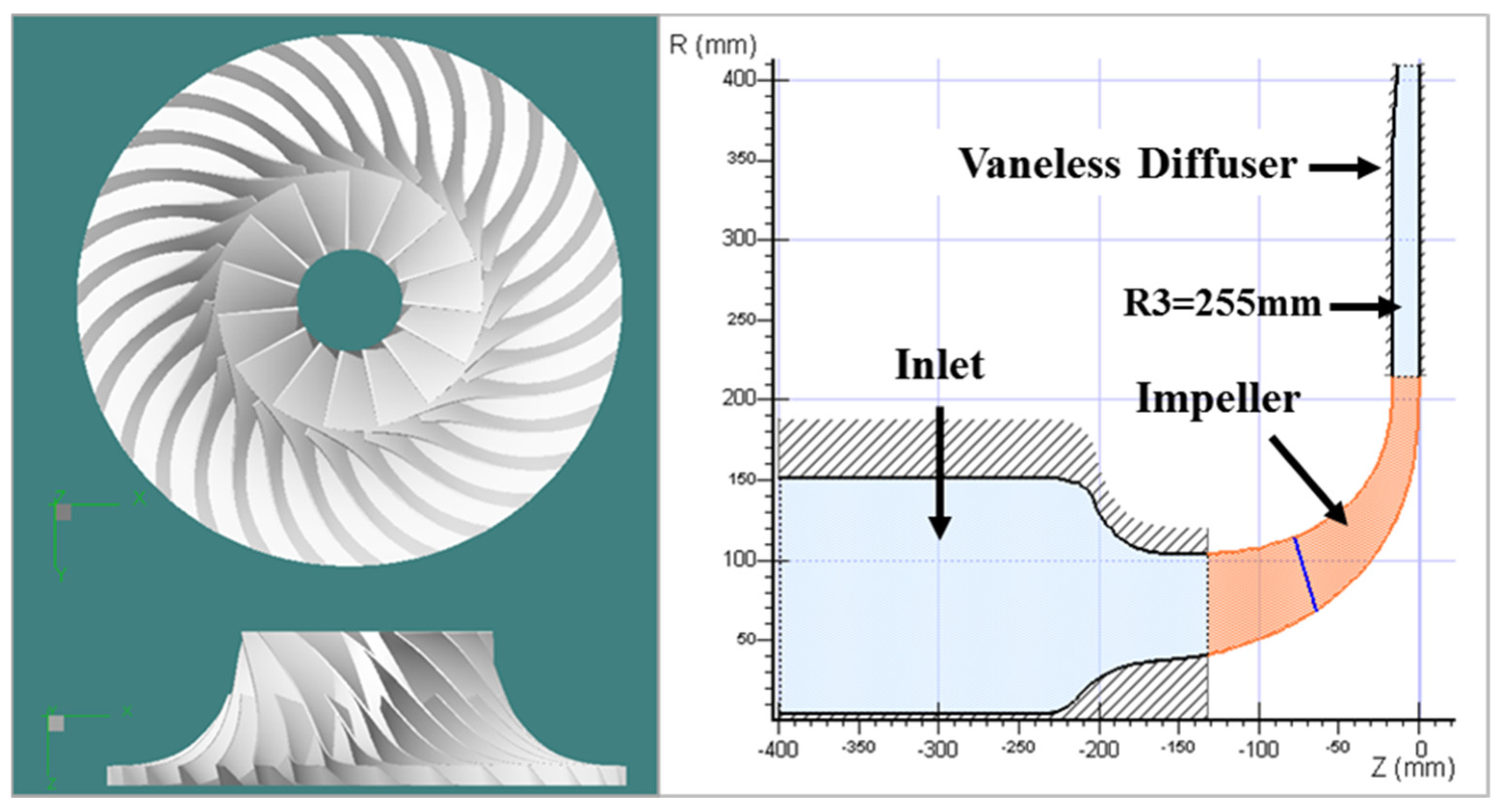
2.1. Compressor Model
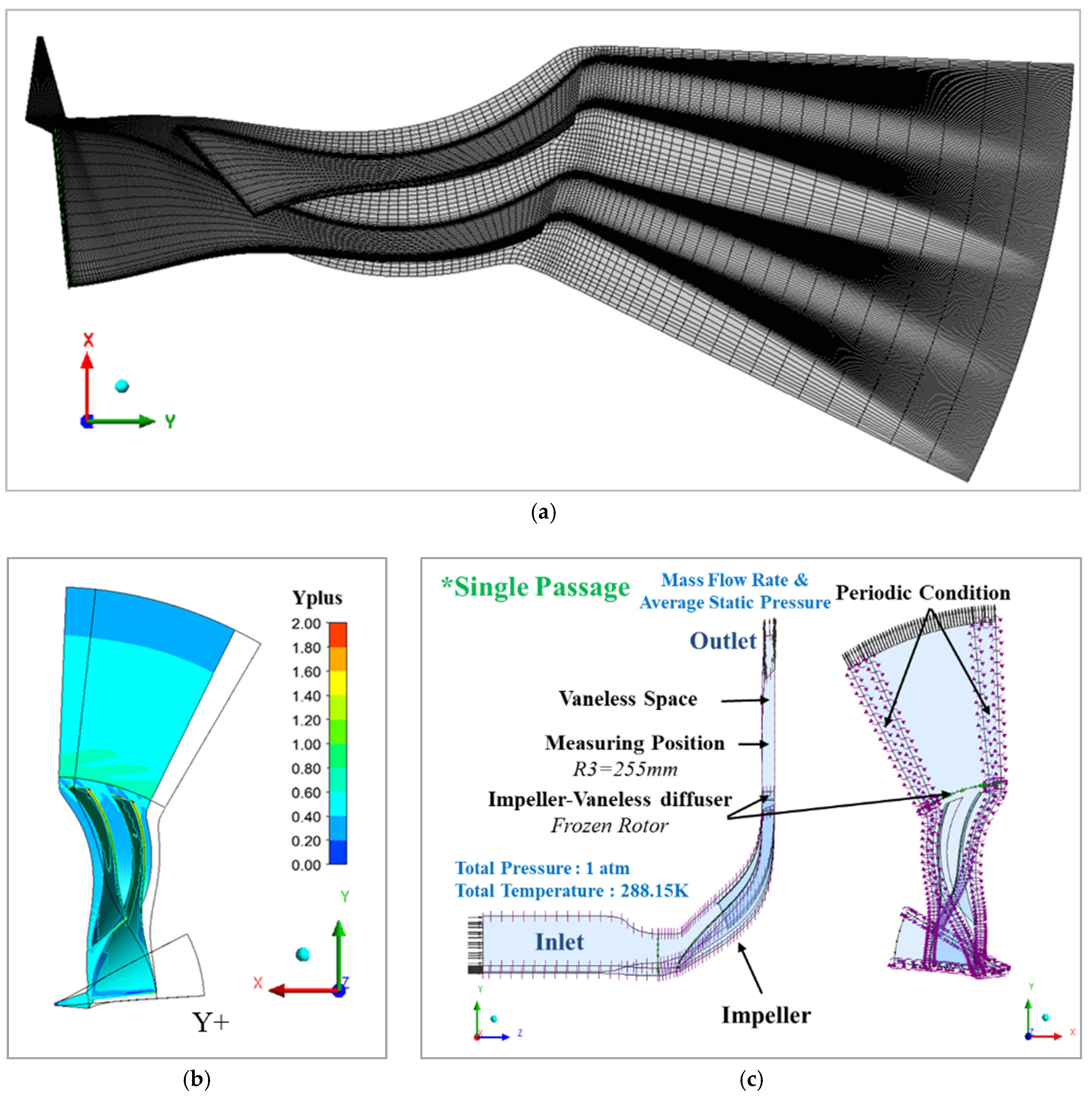
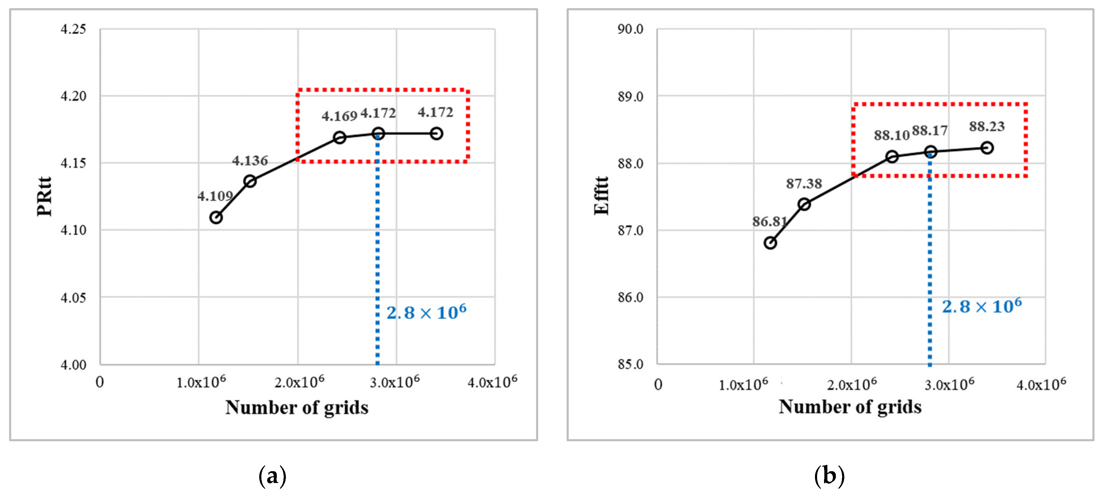
2.2. Computational Grid and Validation
3. Numerical Results
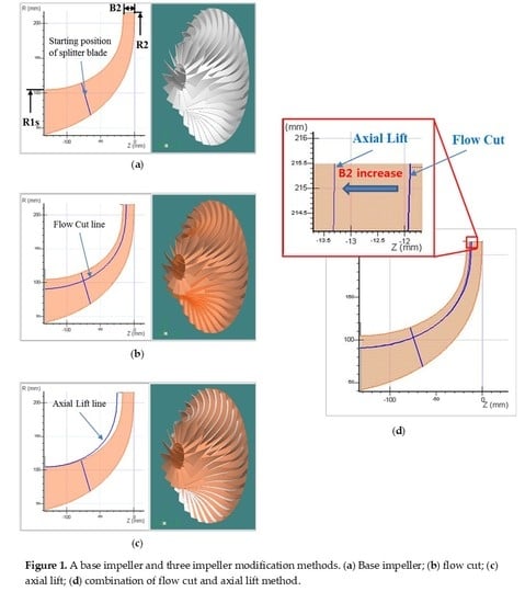
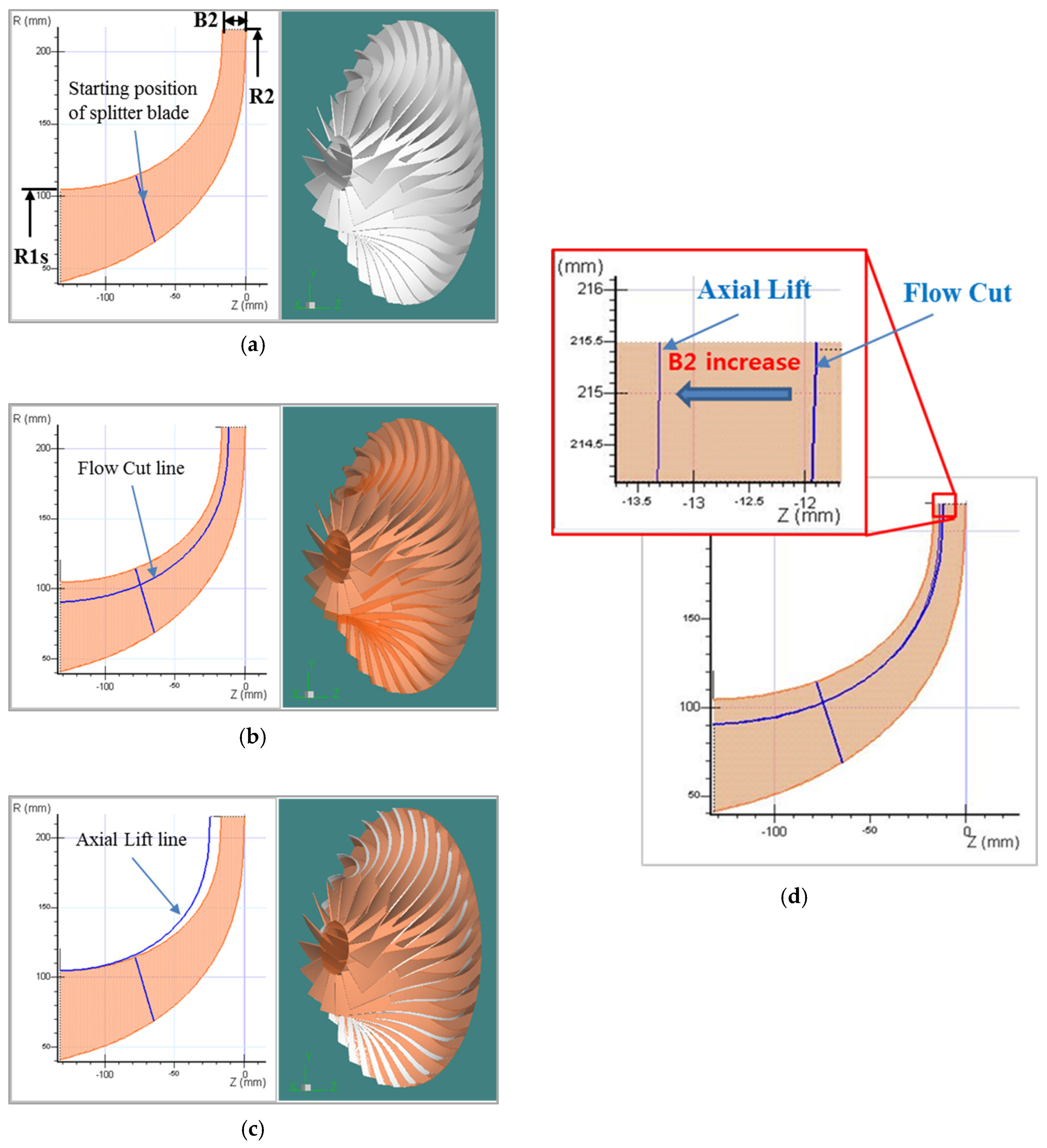
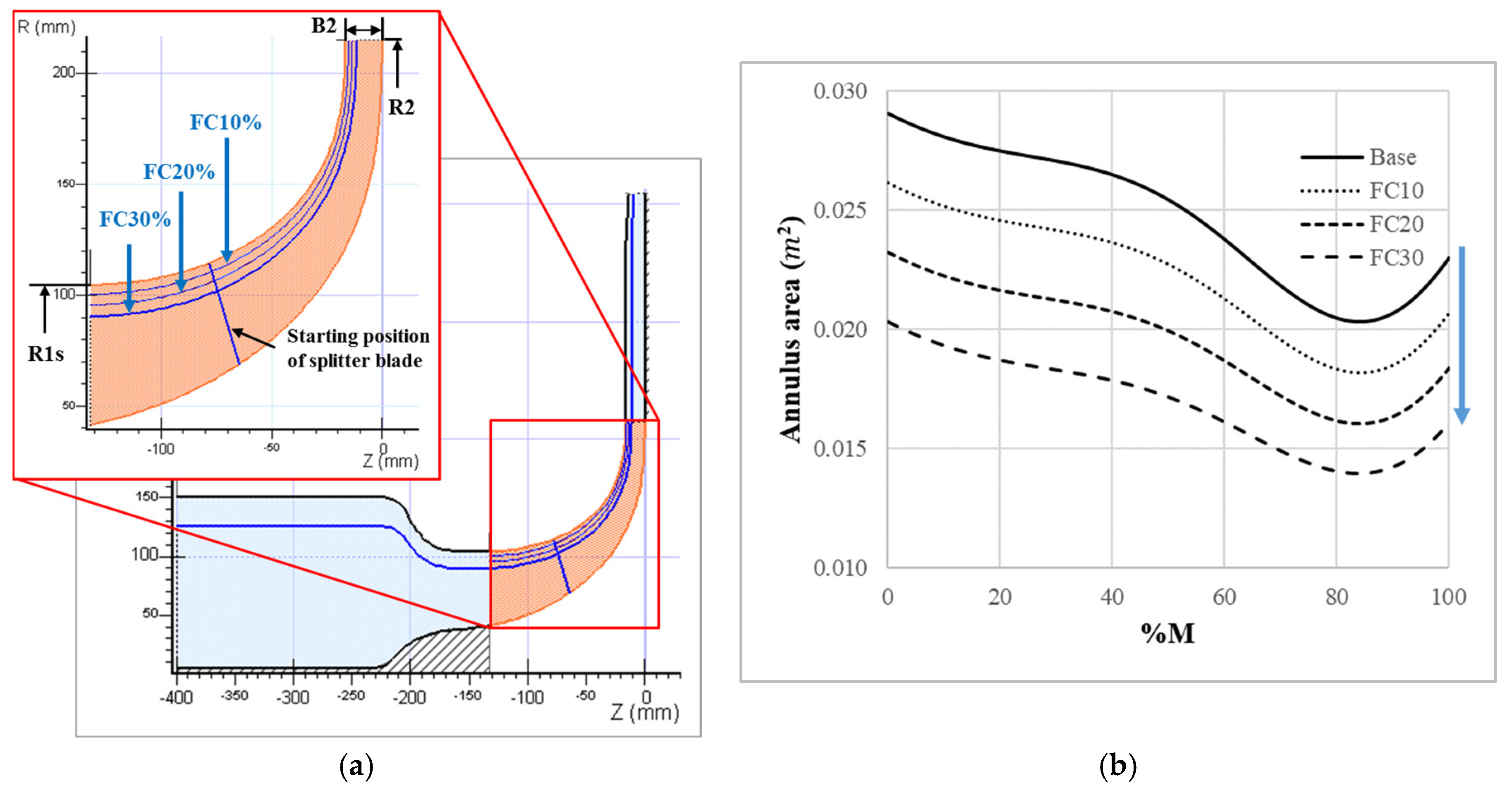
3.1. Flow Cut
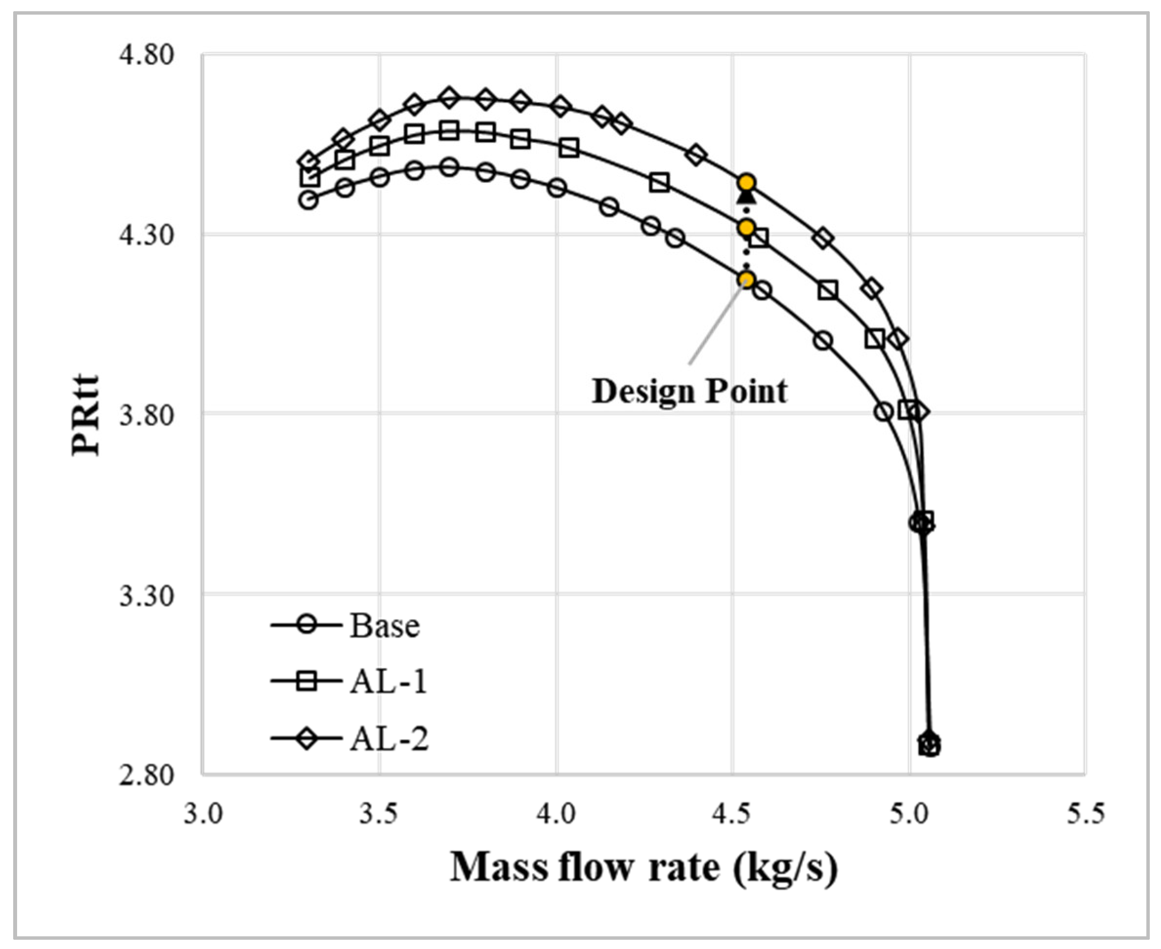
3.2. Axial Lift
3.3. Combination of Flow Cut and Axial Lift
4. Discussion
4.1. Characteristic of Base Impeller
4.2. Correlation of Velocity and Total Pressure at Impeller Exit
4.2.1. Relative Velocity
4.2.2. Tangential/meridional Velocities at the Impeller Exit
4.2.3. Total Pressure at Impeller Exit
5. Conclusions
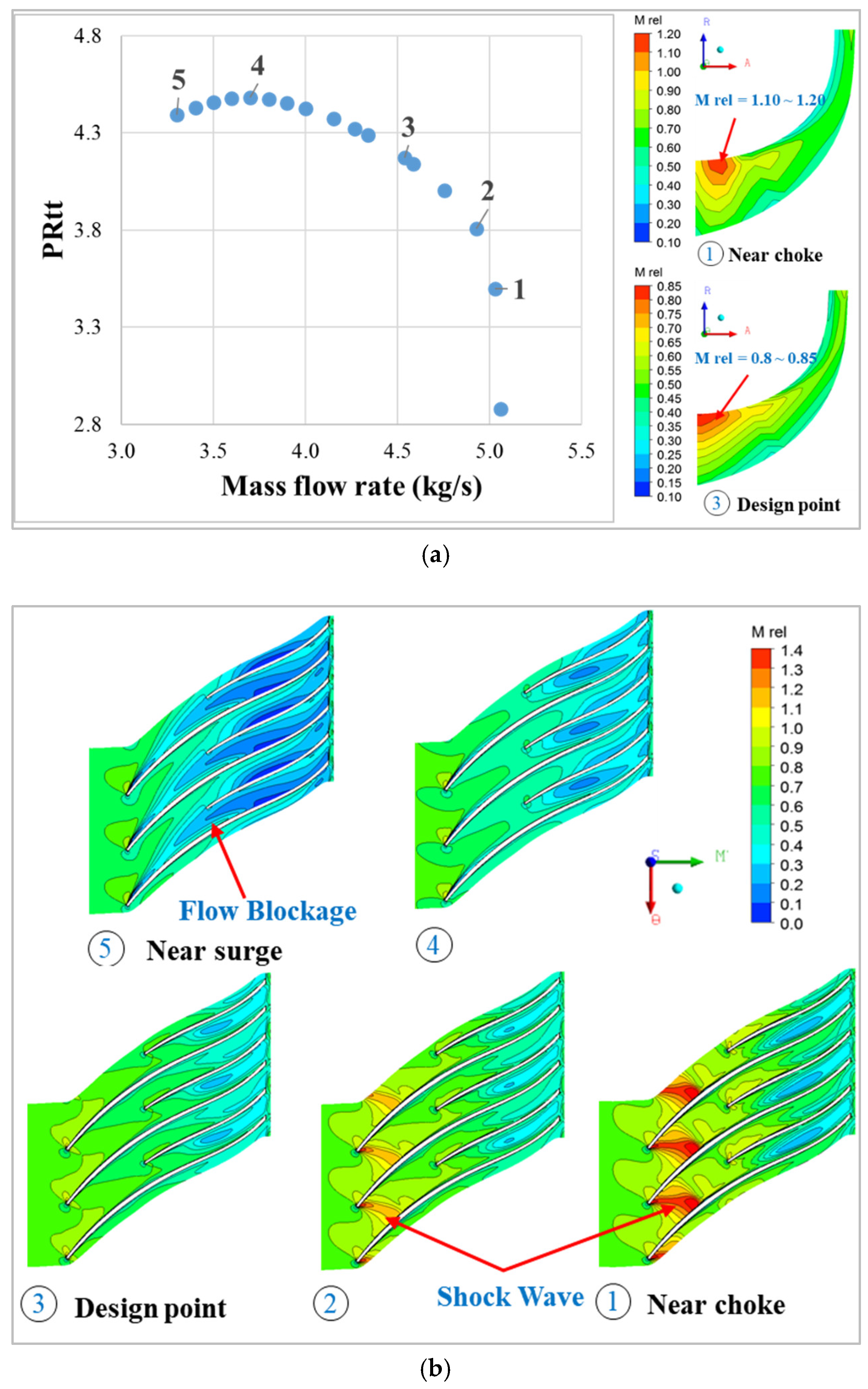
- The NASA CC3 transonic centrifugal compressor with a backswept angle of −50° was used as the base compressor to carry out the study. The aerodynamic performance of the impeller of the base compressor was analyzed. There was a strong shock wave at the impeller inlet tip near the choke; however, in the range of the design point to the surge, no shock wave was observed. Therefore, the high-pressure transonic centrifugal impeller used in this study will be useful for industrial applications when they operate properly within the operating range without shock waves.
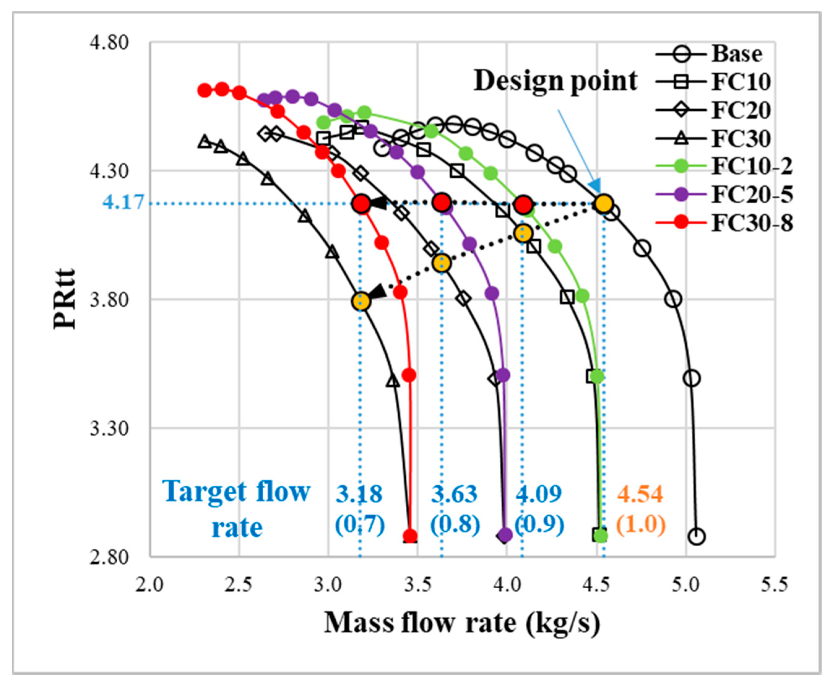
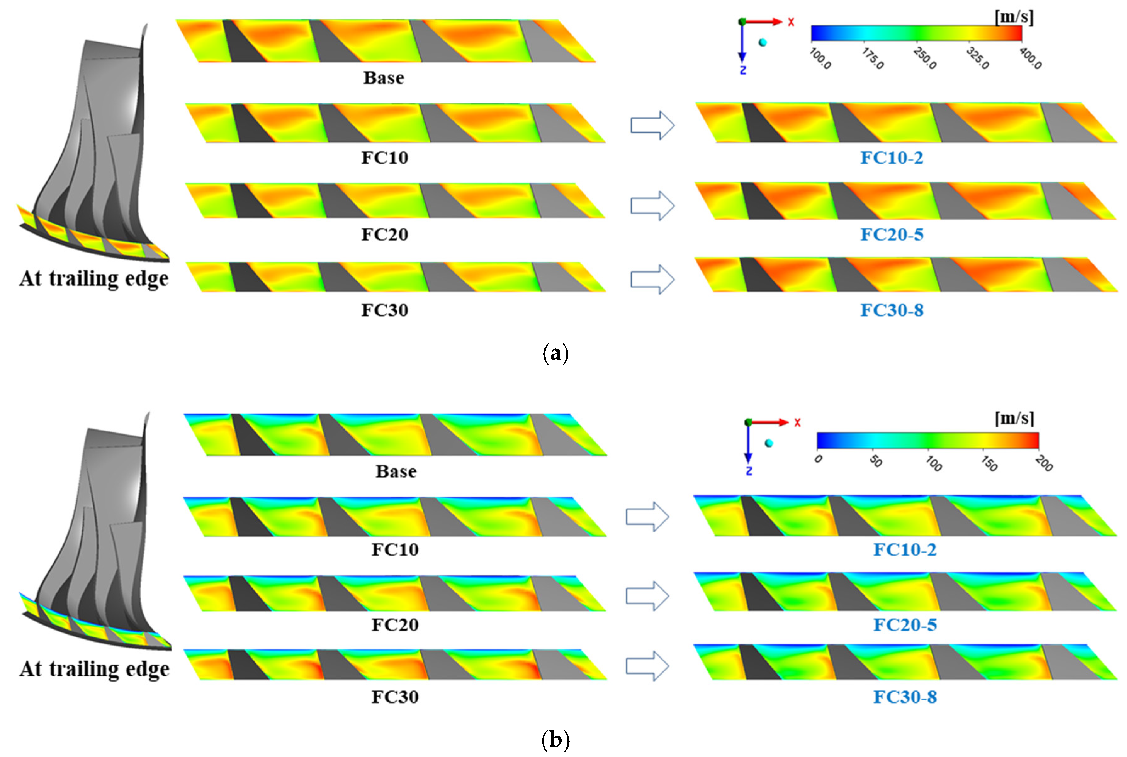
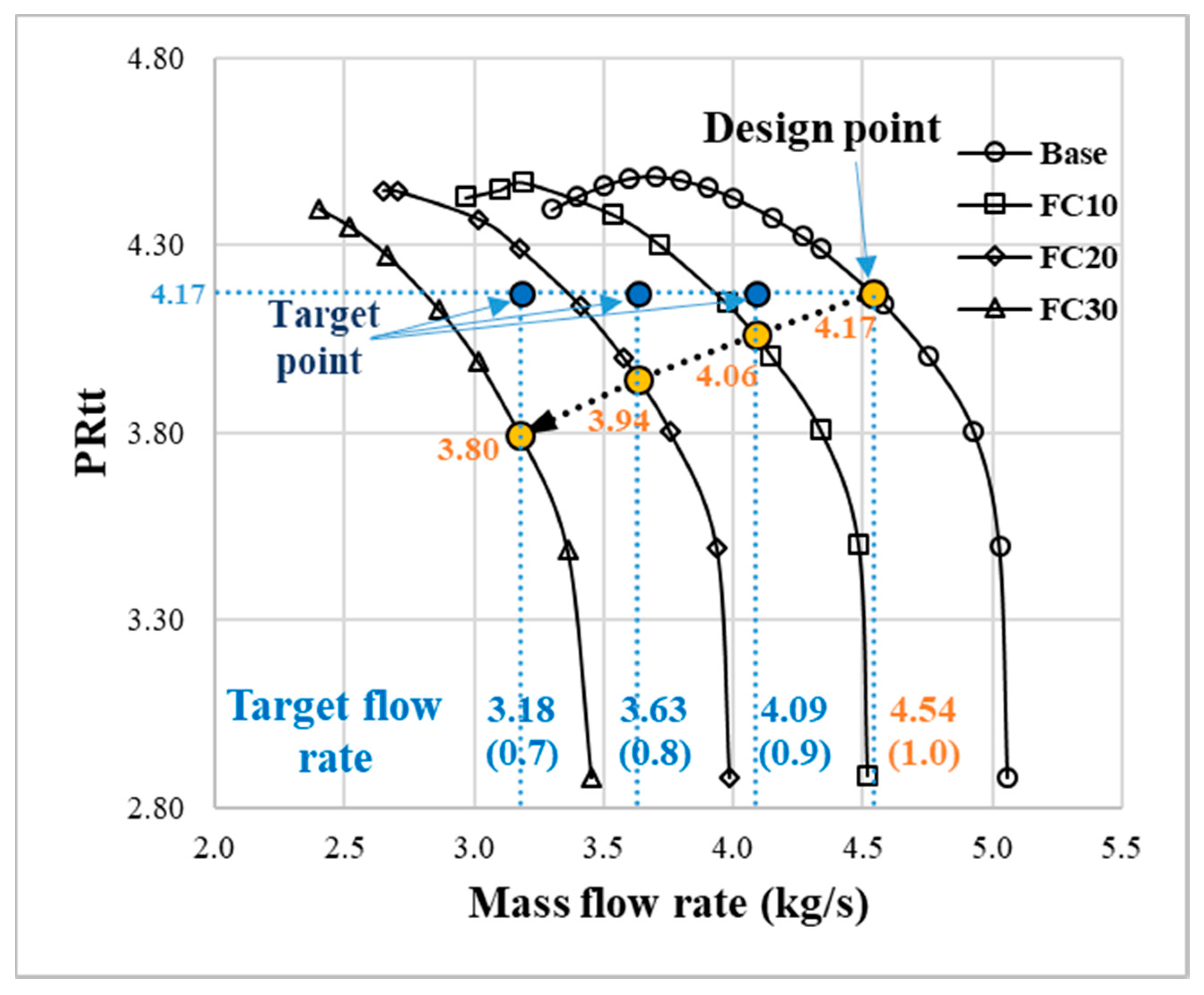
- To analyze the influence of the flow cut method, the target flow rate of the flow cut was set at flow fractions of 0.7, 0.8, and 0.9 compared to the design flow rate. After applying the flow cut, the total pressure at the target flow rate was lower than the total pressure at the design point due to the increase in the relative velocity at the impeller exit. In the centrifugal impeller with a backswept angle, the increased relative velocity reduces the angle of the absolute velocity (Meridional angle convention), which results in a reduction of the tangential velocity and the work coefficient.
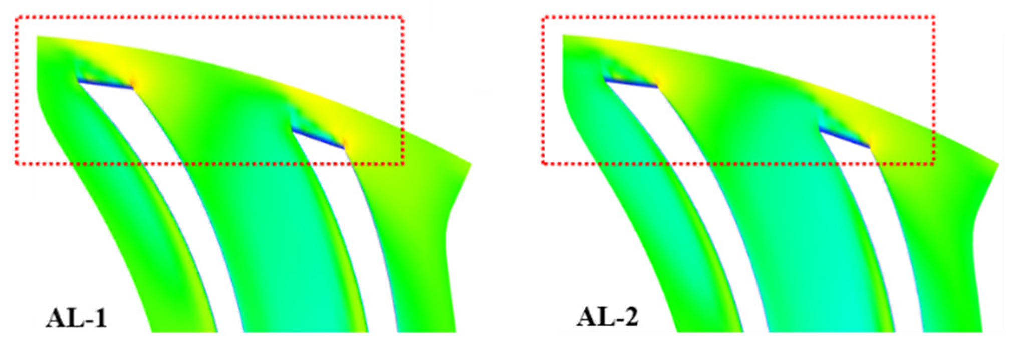
- To analyze the influence of the axial lift, the B2 value was increased by 1 mm and 2 mm compared to the value of the base impeller. After applying the axial lift method, the total pressure at the design flow rate was increased due to the decrease in the relative velocity caused by increasing the passage area at the impeller exit.
- Applying the flow cut and axial lift methods showed that the variation in the relative velocity at the impeller exit has a significant effect on the variation of the total pressure. In addition, it was found that the relative velocity at the impeller exit of the target flow rate is similar to that of the base impeller when the flow cut and axial lift methods are applied together. Therefore, by combining these methods, three transonic centrifugal impellers with flow fractions of 0.7, 0.8, and 0.9 compared to the design flow rate were newly designed. These conclusions are expected to be guidelines to design impellers within a specific flow range by applying impeller modification methods to transonic centrifugal impellers with a backswept angle.
Author Contributions
Funding
Conflicts of Interest
Nomenclature
| AL | Axial lift |
| B | Blade height |
| C | Absolute velocity |
| CFD | Computational fluid dynamics |
| Efftt | Total-to-total efficiency |
| FC | Flow cut |
| M | Mach number |
| Ns | Nondimensional specific speed |
| PR | Pressure ratio |
| PRtt | Total-to-total pressure ratio |
| R | Blade radius |
| RMS | Root mean square |
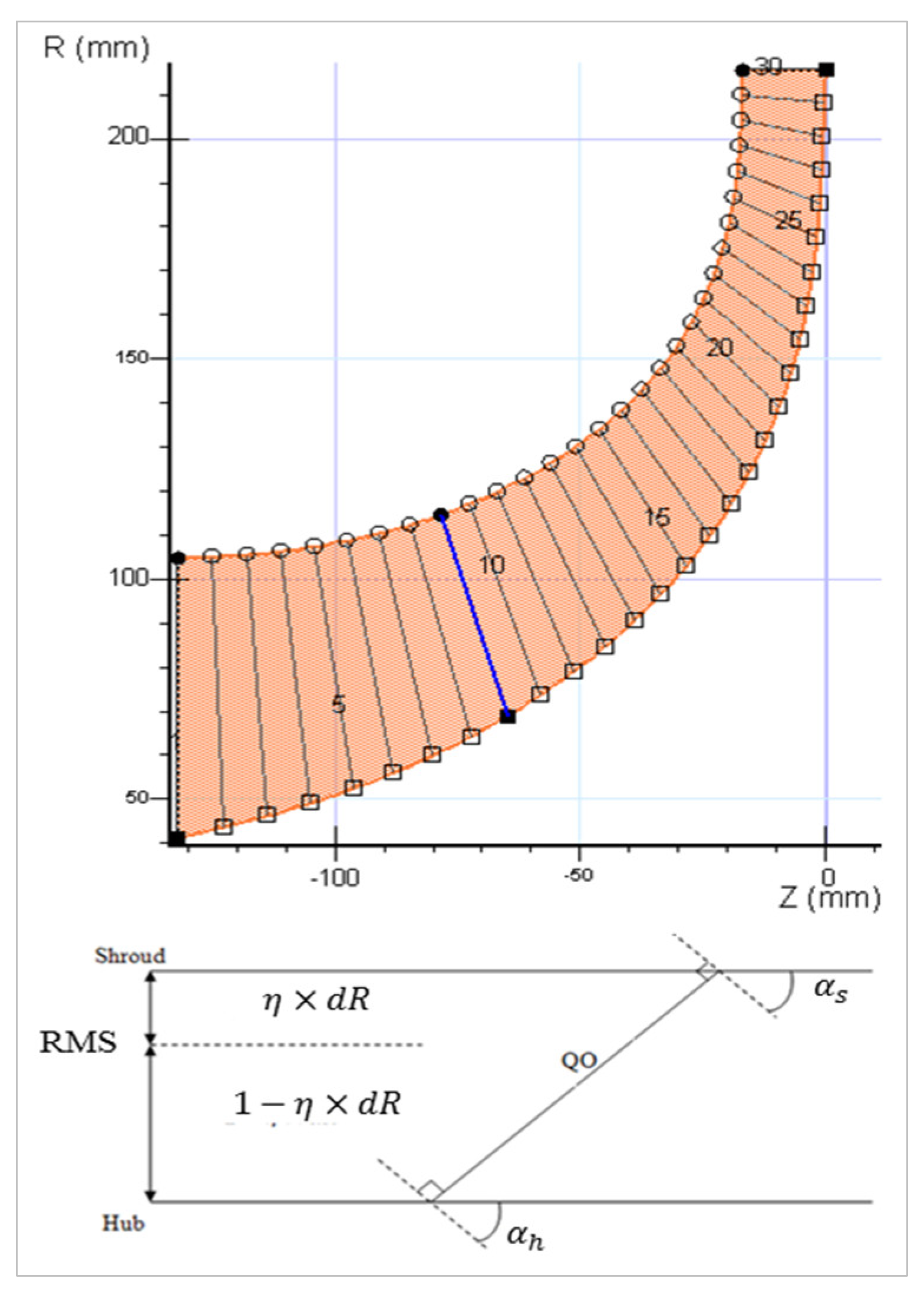
| QO | Quasi-orthogonal |
| U | Blade speed |
| W | Relative velocity |
Mathematical Symbols
| Angle between QO lines and RMS contour | |
| Angle between QO lines and hub contour | |
| Angle between QO lines and shroud contour | |
| Backswept angle | |
| Fraction between the shroud and RMS contour |
Subscripts
| 1 | Impeller inlet |
| 2 | Impeller exit |
| 3 | Measuring position |
| b | Blade |
| h | Hub |
| s | Shroud |
| t | Tip |
| Meridional direction | |
| Tangential direction |
References
- Harvey, S.; Eng, P. Centrifugal Compressors in Ethylene Plants. Chem. Eng. Prog. 2017, 113, 28–32. [Google Scholar]
- Malik, A.; Zheng, Q.; Qureshi, S.R.; Zaidi, A.A.; Ahmad, S.A. Design and aerodynamic analysis of 50 kw combine cooling, heating and power (cchp) micro-gas turbine plant and its vaneless centrifugal compressor. In Proceedings of the 2018 IEEE 5th International Conference on Engineering Technologies and Applied Sciences (ICETAS), Krung, Thailand, 22–23 November 2018; pp. 1–6. [Google Scholar]
- Came, P. The development, application and experimental evaluation of a design procedure for centrifugal compressors. Proc. Inst. Mech. Eng. 1978, 192, 49–67. [Google Scholar] [CrossRef]
- Came, P.; Robinson, C. Centrifugal compressor design. Proc. Inst. Mech. Eng. Part C J. Mech. Eng. Sci. 1998, 213, 139–155. [Google Scholar] [CrossRef]
- Lüdtke, K.H. Process Centrifugal Compressors: Basics, Function, Operation, Design; Application; Springer Science & Business Media: Berlin/Heidelberg, Germany, 2004. [Google Scholar]
- Xu, C. Design experience and considerations for centrifugal compressor development. Proc. Inst. Mech. Eng. Part G J. Aerosp. Eng. 2007, 221, 273–287. [Google Scholar] [CrossRef]
- Xu, C.; Amano, R.S. Empirical design considerations for industrial centrifugal compressors. Int. J. Rotat. Mach. 2012, 2012, 184061. [Google Scholar] [CrossRef]
- Engeda, A. Effect of Impeller Exit Width Trimming on Compressor Performance. In Proceedings of the 8th International Symposium on Experimental and Computational Aerothermodynamics of Internal Flows, Lyon, France, 2–5 July 2007. [Google Scholar]
- Swain, D.; Engeda, A. Performance impact of impeller blade trimming on centrifugal compressors. Proc. Inst. Mech. Eng. Part A J. Power Energy 2014, 228, 878–888. [Google Scholar] [CrossRef]
- Rodgers, C. ASME Turbo Expo 2001: Centrifugal Compressor Blade Trimming for a Range of Flows. In Proceedings of the Power for Land, Sea, and Air, New Orleans, LA, USA, 4–7 June 2001; p. V001T03A020. [Google Scholar]
- David, T.; Zhang, D.; Cave, M. Frictional effects on a base and a flow-trimmed impeller of a low specific speed industrial compressor. In Proceedings of the ASME Turbo Expo 2006: Power for Land, Sea, and Air, Barcelona, Spain, 8–11 May 2006; pp. 1121–1130. [Google Scholar]
- Zhang, D.; Di Liberti, J.-L.; Cave, M. A CFD Study on a Base and a Flow-Trimmed Low Specific Speed Centrifugal Compressor. In Proceedings of the ASME 2010 International Mechanical Engineering Congress and Exposition, Vancouver, BC, Canada, 12–18 November 2010; pp. 89–94. [Google Scholar]
- Swain, D.; Engeda, A. Effect of impeller blade trimming on the performance of a 5.5: 1 pressure ratio centrifugal compressor. Proc. Inst. Mech. Eng. Part A J. Power Energy 2014, 228, 602–613. [Google Scholar] [CrossRef]
- Shin, B.G.; Lee, S.H.; Cho, J.J.; Lim, K.S.; Kim, K.Y. Numerical Analysis on the Performance Characteristics of a Centrifugal Compressor for Derived Design Parameters. Proc. Korean Soc. Mech. Eng. 2015, 11, 1455–1459. [Google Scholar]
- Shin, B.G.; Lim, K.S.; Kim, K.Y.; Lim, C.S. A New Method for Predicting the Performance Map of a Single Stage of a Centrifugal Compressor. In Proceedings of the 1st Global Power and Propulsion Forum, Zurich, Switzerland, 16–18 January 2017. [Google Scholar]
- Sayers, A.T. Hydraulic and Compressible Flow Turbomachines; McGraw-Hill: New York, NY, USA, 1990. [Google Scholar]
- Japikse, D.; Baines, N. Introduction to Turbomachinery; Concepts NREC: White River Junction, VT, USA, 1994. [Google Scholar]
- David, J. Centrifugal Compressor Design and Performance; Concepts NREC: White River Junction, VT, USA, 1996. [Google Scholar]
- Ronald, H. Centrifugal Compressors: A Strategy for Aerodynamic Design and Analysis; AMSE Press: New York, NY, USA, 2000. [Google Scholar]
- McKain, T.F.; Holbrook, G.J. Coordinates for a High Performance 4: 1 Pressure Ratio Centrifugal Compressor; NASA Lewis Research Center: Indianapolis, IN, USA, 1997. [Google Scholar]
- Menter, F.R.; Kuntz, M.; Langtry, R. Ten years of industrial experience with the SST turbulence model. Turbul. Heat Mass Transf. 2003, 4, 625–632. [Google Scholar]
- Kulkarni, S.; Beach, T.A.; Skoch, G.J. Computational study of the CC3 impeller and vaneless diffuser experiment. In Proceedings of the 49th AIAA/ASME/SAE/ASEE Joint Propulsion Conference, San Jose, CA, USA, 14–17 July 2013; p. 3631. [Google Scholar]


| Specifications | |
|---|---|
| Exit rating station ( (Measuring position/Impeller exit radius) | 1.18 |
| Impeller main blade/splitter blade | 15 / 15 |
| Design speed | 21,789 RPM |
| Design flow rate | 4.54 kg/s |
| Tip speed at impeller exit () | 492 m/s |
| Hub radius at impeller inlet () | 41.4 mm |
| Shroud radius at impeller inlet () | 105 mm |
| Blade width at impeller exit () | 17 mm |
| Radius at impeller exit () | 215.5 mm |
| Impeller backswept angle ( | 50° |
| Impeller axial length | 132.25 mm |
| Nondimensional specific speed (Ns) | ~ 0.57 |
| - | Impeller Inlet | Impeller Exit | ||||
|---|---|---|---|---|---|---|
| R1s (mm) | Annulus Area | B2 (mm) | Annulus Area | |||
| Area (m2) | Decreased Ratio | Area (m2) | Decreased Ratio | |||
| Base | 105.00 | 0.02906 | - | 17.0 | 0.02300 | - |
| FC 10 | 100.43 | 0.02615 | 0.9 | 15.3 | 0.02070 | 0.9 |
| FC 20 | 95.67 | 0.02324 | 0.8 | 13.6 | 0.01840 | 0.8 |
| FC 30 | 90.70 | 0.02033 | 0.7 | 11.9 | 0.01610 | 0.7 |
| - | Impeller Inlet | Impeller Exit | ||||
|---|---|---|---|---|---|---|
| R1s (mm) | Annulus Area | B2 (mm) | Annulus Area | |||
| Area (m2) | Increased Ratio | Area (m2) | Increased Ratio | |||
| Base | 105.00 | 0.02906 | - | 17.0 | 0.02300 | - |
| AL 1 | 105.00 | 0.02906 | 1.0 | 18.0 | 0.02436 | 1.06 |
| AL 2 | 105.00 | 0.02906 | 1.0 | 19.0 | 0.02571 | 1.12 |
| R1s (mm) | B2 | ||
|---|---|---|---|
| Width (mm) | Increased Percentage (%) | ||
| FC10 | 100.43 | 15.3 | - |
| FC10-1 | 15.6 | ~ 2% | |
| FC10-2 | 15.9 | ~ 4% | |
| FC20 | 95.67 | 13.6 | - |
| FC20-1 | 13.9 | ~ 2% | |
| FC20-2 | 14.1 | ~ 4% | |
| FC20-3 | 14.4 | ~ 6% | |
| FC20-4 | 14.7 | ~ 8% | |
| FC20-5 | 14.9 | ~ 9.5% | |
| FC30 | 90.70 | 11.9 | - |
| FC30-1 | 12.1 | ~ 2% | |
| FC30-2 | 12.4 | ~ 4% | |
| FC30-3 | 12.6 | ~ 6% | |
| FC30-4 | 12.9 | ~ 8% | |
| FC30-5 | 13.1 | ~ 10% | |
| FC30-6 | 13.3 | ~ 12% | |
| FC30-7 | 13.6 | ~ 14% | |
| FC30-8 | 13.8 | ~ 16% | |
© 2019 by the authors. Licensee MDPI, Basel, Switzerland. This article is an open access article distributed under the terms and conditions of the Creative Commons Attribution (CC BY) license (http://creativecommons.org/licenses/by/4.0/).
Share and Cite
Park, K.S.; Jung, I.H.; You, S.J.; Lee, S.Y.; Zamiri, A.; Chung, J.T. Influences of the Flow Cut and Axial Lift of the Impeller on the Aerodynamic Performance of a Transonic Centrifugal Compressor. Energies 2019, 12, 4503. https://doi.org/10.3390/en12234503
Park KS, Jung IH, You SJ, Lee SY, Zamiri A, Chung JT. Influences of the Flow Cut and Axial Lift of the Impeller on the Aerodynamic Performance of a Transonic Centrifugal Compressor. Energies. 2019; 12(23):4503. https://doi.org/10.3390/en12234503
Chicago/Turabian StylePark, Kun Sung, In Hyuk Jung, Sung Jin You, Seung Yeob Lee, Ali Zamiri, and Jin Taek Chung. 2019. "Influences of the Flow Cut and Axial Lift of the Impeller on the Aerodynamic Performance of a Transonic Centrifugal Compressor" Energies 12, no. 23: 4503. https://doi.org/10.3390/en12234503
APA StylePark, K. S., Jung, I. H., You, S. J., Lee, S. Y., Zamiri, A., & Chung, J. T. (2019). Influences of the Flow Cut and Axial Lift of the Impeller on the Aerodynamic Performance of a Transonic Centrifugal Compressor. Energies, 12(23), 4503. https://doi.org/10.3390/en12234503