Abstract
Broken rotor bar (BRB) faults are one of the most common faults in induction motors (IM). One or more broken bars can reduce the performance and efficiency of the IM and hence waste the electrical power and decrease the reliability of the whole mechanical system. This paper proposes an effective fault diagnosis method using the Teager–Kaiser energy operator (TKEO) for BRB faults detection based on the motor current signal analysis (MCSA). The TKEO is investigated and applied to remove the main supply component of the motor current for accurate fault feature extraction, especially for an IM operating at low load with low slip. Through sensing the estimation of the instantaneous amplitude (IA) and instantaneous frequency (IF) of the motor current signal using TKEO, the fault characteristic frequencies can be enhanced and extracted for the accurate detection of BRB fault severities under different operating conditions. The proposed method has been validated by simulation and experimental studies that tested the IMs with different BRB fault severities to consider the effectiveness of the proposed method. The obtained results are compared with those obtained using the conventional envelope analysis methods and showed that the proposed method provides more accurate fault diagnosis results and can distinguish the BRB fault types and severities effectively, especially for operating conditions with low loads.
1. Introduction
Broken rotor bars (BRB) are frequent faults that represent around 9%, according to the IEEE, among all kinds of induction motor (IM) faults [1]. As the performance and efficiency of the IM are thoroughly affected by BRB faults, early BRB fault diagnosis plays a major part in ensuring the IMs’ work safety, reliability, and energy saving [2]. The variation of rotor resistance caused by BRB faults can affect the motor current directly and enhance its modulation characteristics. Therefore, motor current signal analysis (MCSA) is widely used to detect BRB faults based on modulation characteristic analysis [3]. With the advantages of non-invasion, low cost, and the ability to operate without needing any extra sensors installed, MCSA has successfully attracted researchers’ attention for detecting BRB faults with various kinds of measurements, such as vibration, acoustic, and temperature, et al. [4,5]. Furthermore, various signal processing methods have been developed and investigated for motor current signatures analysis [6,7]. Spectral analysis based on fast Fourier transform (FFT) is a conventional method that has been widely applied in MCSA. BRB fault characteristic frequency can be identified and extracted for BRB fault detection based on the spectral analysis of the motor current signal [3]. However, the low fault frequency that is modulated on the main supply frequency, especially under lower operating loads with low slip, limits the accurate spectral analysis of BRB fault detection, as the leakage of the main supply frequency can hide the fault frequency components [8]. This is a major difficulty of the spectral analysis method for accurate fault feature extraction based on MCSA.
Many advanced signal-processing methods have been investigated and developed for the accurate fault diagnosis of IMs by removing the strong influence of the main supply components on fault feature extraction [9,10,11,12]. Gu et al. [13] proposed the modulation signal bispectrum method-based sideband estimator (MSB-SE) by achieving the amplitudes at a BRB fault characteristic frequency. The results verified that the proposed method is effective in both detecting the BRB fault and predicting BRB severity under loads no lower than 25%. Sapena-Bano at al. [14] applied the reduced envelope analysis (REA) for a BRB fault detection with low computational resources and found that BRB faults can be detected under different operations. de Jesus et al. [15] performed the mathematical morphology (MM) for BRB fault diagnosis based on MCSA in which the tested loads ranged from 25% to 100% for different cases that were carried out to verify the efficiency of the proposed technique. It found that the selected frequency processed by MM could better indicate the BRB fault than the BRB fault characteristic frequency. These above-mentioned methods can extract the fault-related frequency components effectively for BRB fault identification and detection based on the demodulation analysis. However, most of them only take into account the analyzed signal as a modulation signal during the process, but cannot distinguish whether the modulation sideband is caused by amplitude modulation (AM) or frequency modulation (FM) [16]. Therefore, it is necessary to accurately separate AM and FM from the modulation sidebands for accurate fault mode identification.
Envelope analysis based on Hilbert transform (HT) is a typical demodulation technique that has been used for decades and provides much more diagnostic information than the conventional spectral analysis [14]. The analytic signal constructed by HT contains amplitude and phase information, which can be used to reflect the envelope of a signal [12]. Wang et al. [17] applied Hilbert transform to demodulate the signal for bearing fault diagnosis. Trajin [18] proposed the Concordia transform to construct a complex vector based on a two-phase current signal from a three-phase AC IM. The space vector is able to separate the diagnosis signal and achieve the demodulation purpose. Even envelope analysis has been widely applied in machinery fault diagnosis, it mainly focuses on the demodulation of AM while ignoring the FM component in the analyzed signal. For an IM with BRB faults, the main supply current is modulated with BRB fault frequency by AM and FM simultaneously. It is hard to demodulate the BRB fault characteristic frequency under low loads, especially no loads [19], because (1) the AM characteristic is not obvious under low loads, which means that the FM characteristic of the signal cannot be ignored; and (2) the slip under low loads or no loads is very small, which makes the BRB fault characteristic frequency also very small and close to 0 Hz. This means that the amplitude of the modulated component related to fault severities is more easily influenced by the leakage of the main supply components [19,20]. Therefore, a method that can be used to demodulate the AM and FM components simultaneously in the time domain needs to be investigated for BRB fault detection, especially at low motor slip.
The Teager–Kaiser energy operator (TKEO) is a demodulation method that can effectively demodulate the AM and FM signals simultaneously in the time domain and has attracted researchers’ interests by its ability to improve the signal-to-noise ratio and be completed in real time, as well as its low computational consumption [21,22,23]. Pineda et al. [8] applied TKEO in detecting IM faults including broken bars, mixed eccentricity, and single-point bearing faults using MCSA. As the adverse effect of spectral leakage is reduced by TKEO, the analysis results show superiority with high efficiency and accuracy for an offline IM faults diagnosis system. Zhao et al. [24] expound that TKEO can successfully detect impact signals and is proper for processing non-stationary signals; therefore, it is useful in wind turbine bearing fault diagnosis using vibration signals. In their study, simulation work and experimental work were carried out and certified that the proposed method is effective in extracting fault features. The results also show excellence in comparison with empirical mode decomposition and conventional spectral analysis. Khoshnami et al. [25] found that the TKEO algorithm can be used to detect the photovoltaic fault conditions as well as further distinguish string-to-ground, string-to-string, and open-circuit faults. The fault indicator achieved by their proposed method used limited computational resources without a huge dataset and costly sensors. Patricia et al. [26] transformed vibration signals using the TKEO method for bearing faults detection, and the experimental analysis results showed that the computation of the TKEO is simpler and faster than band-pass filtering. Liu et al. [27] detected stator inter-turn faults by analyzing inverter common-mode voltage using TKEO. In their research, the TKEO method was used to improve the signal-to-noise ratio (SNR) and extract the faults severities effectively. As a method for determination of the amplitude and frequency of a signal, TKEO was also developed to analyze the speech and evaluated to be effective in car and multi-talker babble noise environments [28].
With the function of demodulating AM and FM, TKEO is proposed in this paper to process the measured motor current signal for BRB fault diagnostics. The proposed method is validated both in simulation and experimental studies for fault types and severities identification and classification. Moreover, the analysis results are compared with conventional envelope analysis, which was proposed to be an effective AM signal demodulation technique. The comparison results show that the TKEO is effective in demodulating the BRB fault-related components for fault feature extraction, even under no load conditions.
This paper is organized as follows. Section 2 briefly introduces the basic theory of a motor current signal model with the BRB fault and the TKEO method. Section 3 presents the simulation analysis to demonstrate that the TKEO is effective in demodulating the AM signal and FM signal. Section 4 introduces the test rigs and test details along with the analysis results, followed by a discussion in Section 5. Section 6 draws the conclusions.
2. Current Signal Model and TKEO
2.1. Motor Current Signal for BRB
In induction motors, additional components will be induced and modulated in the main supply stator current when BRB faults happen [13]. The fault frequency can be expressed as in Equation (1):
where and represent the slip and the main supply frequency, respectively. can be expressed by Equation (2):
where and represent the synchronize speed and the rotor speed, respectively. is the number of the pole pairs of the IM.
By considering the amplitude, phase change, and its effect in linkage flux etc., the motor current signal in phase A () in healthy induction motors and those with BRB faults () can be presented in Equations (3) and (4) correspondingly.
where is the root mean square (RMS) of the main supply current; and is the linkage flux. , , and represent the phases of the main supply current, flux, and BRB, respectively. and are the phase by the winding impedance and corresponding sidebands. is the amplitude of the lower sideband in the RMS value. represents the modulus of the sideband components due to speed oscillation, which was caused by BRB faults.
2.2. Teager–Kaiser Energy Operator
TKEO is an energy-tracking operator that is used to estimate the instantaneous energy of a signal in the time domain. It was first proposed by Teager [28] for application in speech analysis [29] and derived by Kaiser [30], and it is efficiently and effectively estimated from three adjacent samples in real-time. The TKEO is defined in both continuous and discretized forms [31] as expressed in Equations (5) and (6), respectively.
For the current signal of the IM shown in Equation (7), with slowly varying amplitude and a frequency whose first derivative can be ignored [32],
where ; then,
Then,
Based on Equations (11) and (12), the instantaneous amplitude (IA) and instantaneous frequency (IF) formulas using TKEO can be derived and expressed in Equations (13) and (14), respectively [31].
3. Simulation Study
In most cases of the machinery fault diagnostics, the modulation sideband caused by the fault around the carrier frequency components includes AM and FM components simultaneously. To validate the capability of the TKEO for AM and FM components’ demodulation and separation, a simulation study is carried out mathematically. A simulated signal including the pure AM component at the frequency of is given in Equation (15); a simulated signal including the pure FM component at the frequency of is given in Equation (16); a simulated signal including the AM and FM components simultaneously is expressed in Equation (17). The simulated carrier frequency for the three modulated signals is .
where is the AM factor and is the FM factor, which are used to set up the degree of AM and FM, respectively. is the amplitude of the simulation signal, which is set up to 1 in the simulation studies.
Two cases are carried out to validate the performance of the TKEO in the separation of AM and FM components. In the first case, the frequency of the AM component is not equal to that of the FM component (), and the frequencies of AM and FM are same in the second case (). The parameters for Equations (15)–(17) are set up as listed in Table 1.

Table 1.
Parameters’ setup for simulations.
Figure 1 presents the waveform and the corresponding spectrum of the three types of simulation signals. The AM signal means that the carrier signal is only modulated in the AM mode, while the FM signal means that the carrier signal is only modulated in the FM mode, and AM+FM means that the carrier signal is modulated in the AM and FM modes simultaneously. All the simulation signals are added Gaussian noise with the signal-to-noise ratio of 30 dB. It can be seen from Figure 1 that the modulation sidebands induced by AM and FM are well presented in the spectrum. Then, the TKEO method is applied to analyze the simulation signal shown in Figure 1a,c,e, respectively, and the waveform and the corresponding spectrum of the processed signal by TKEO are shown in Figure 2.
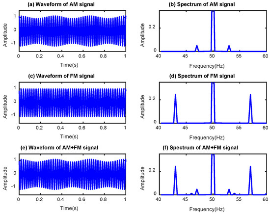
Figure 1.
Waveform and spectrum of the simulation signals.
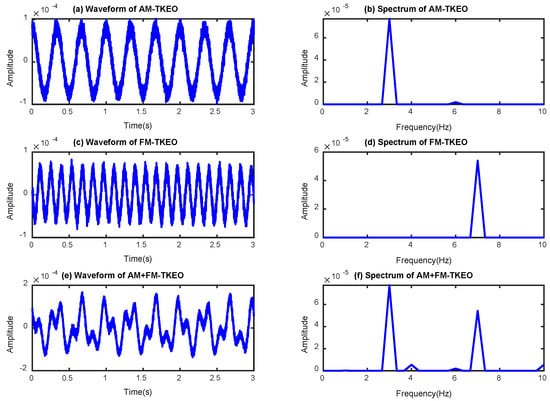
Figure 2.
Waveform and spectrum of the processed signal by the Teager–Kaiser energy operator (TKEO).
From the waveform of the processed signal using the TKEO as shown in Figure 2a,c,e, it demonstrates that the TKEO of the AM, FM, and AM+FM signals can reveal the modulation effects effectively. According to the spectrum of the TKEO of the three types of signals, as shown in Figure 2b,d,f, the TKEO cannot only expose the modulation sideband caused by the AM or FM individually, but also can extract the modulation sideband caused by the AM and FM simultaneously.
For comparison analysis, envelope analysis is employed to analyze the simulation signal shown in Figure 1a,c,e, and the corresponding envelope spectrum for the three types of simulation signals are presented in Figure 3a,c,e. It can be seen from Figure 3a,e that the envelope analysis is able to demodulate the AM components effectively, but cannot exhibit the FM components when the analyzed signal is modulated in FM modes, as shown in Figure 3c,e. It demonstrates that the TKEO method can be used to exhibit the modulation sideband caused by AM and FM simultaneously.
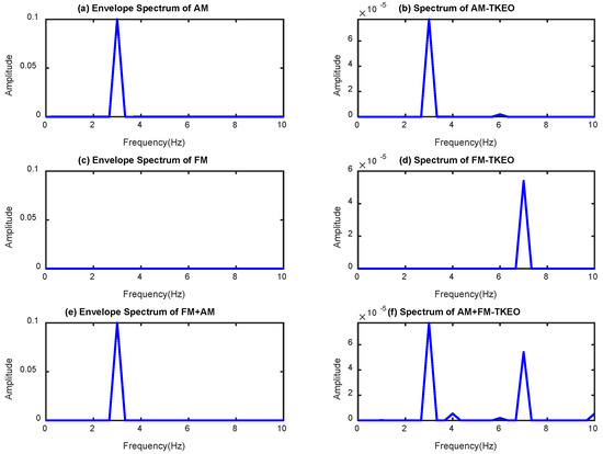
Figure 3.
Comparison analysis of envelope and TKEO.
In order to separate the AM and FM from the modulation sideband using TKEO, the instantaneous amplitude (IA) and instantaneous frequency (IF) are calculated by Equations (13) and (14). The spectrum of IA and IF for the simulation signals are presented in Figure 4. Comparing the spectrum of IA based on the TKEO analysis as shown in Figure 4a,c,e to the envelope spectrum as shown in Figure 3a,c,e, it was found that the instantaneous amplitude based on the TKEO analysis can obtain similar results with that of the envelope analysis. In addition, through analyzing the spectrum of IF based on the TKEO analysis as shown in Figure 4b,d,f, it found that the IF can expose the modulation sideband caused by FM effectively. This demonstrates that the IA can be used to exhibit the AM components in the modulation signal, while the IF can be applied to reveal the FM components in the modulation signal. Therefore, the AM and FM from the modulation sideband can be separated effectively using IA and IF based on the TKEO analysis.
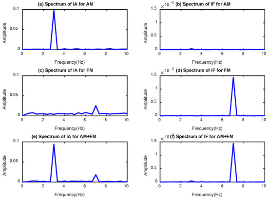
Figure 4.
Spectrum of instantaneous amplitude (IA) and instantaneous frequency (IF) based on TKEO analysis.
In addition, the frequency of the AM and FM components is set up as the same value (7 Hz) as that in Case 2 of the simulation study. The IA and IF spectrum for Case 2 are shown in Figure 5. It can be seen that even the modulation frequency of AM and FM are the same and modulated on the carrier signal simultaneously; the IA and IF can separate the AM and FM components from the modulation sideband effectively.
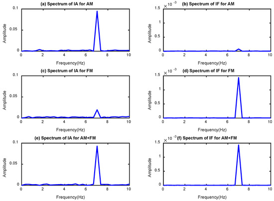
Figure 5.
Spectrum of IA and IF based on TKEO analysis when .
4. Experimental Setup and Test Procedure
To validate the performance of the proposed method on BRB fault diagnostics for IMs based on MCSA, the experiment study is carried out on an IM test bench for different fault detection.
The diagram of the IM test bench shown in Figure 6 consists of an AC drive motor, a flexible coupling, and a DC load generator. The driving AC motor is a three-phase AC induction motor with the power of 4 kW, a rated speed of 1420 rpm, and two pole pairs. The detailed specifications of the test IM are listed in Table 2. A load generator is coupled to the AC motor directly by using flexible couplings. The coupling is a three-jaw hard rubber with a size of 150 mm and can provide 100 kW at a speed of 1600 rpm. The AC motor is controlled by a feedback control system. In such a system, the real operating speed is measured and sent to the controller in real time. Then, the controller of the IM driver will automatically adjust the main supply frequency to achieve the best approximation of the expected operating speed, which has been set. The encoder, which is installed at the end of the IM, outputs 100 pulses and 1 pulse per revolution for the instantaneous speed measurement. The devices for measuring the motor current are Hall-effect current transducers with the measuring range from 0 to 50 A with the tolerance of ±0.005 mA. The outputs of the encoder sensor together with the three current sensor are digitalized by a 16-channel, 24-bit data acquisition system, and the sampling frequency is setup at 96 kHz for data recording during the tests. The detail data acquisition system parameters are shown in Table 3.
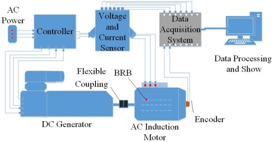
Figure 6.
The diagram of the induction motors (IM) test system.
Table 2.
Specifications of a test IM.
Table 3.
Specifications of the data acquisition system.
The IMs with two kinds of rotor bar faults were tested under different operating conditions for motor current signal measurement. The two fault cases are rotors with 1 BRB and 2 BRB, as shown in Figure 7. The BRB faults are bar breakages that have been artificially produced by drilling one bar to its full depth.
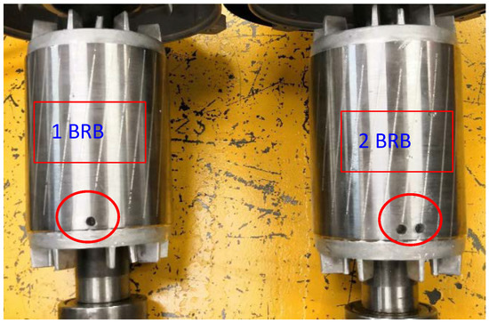
Figure 7.
Rotor fault cases of 1 broken rotor bar (BRB) (left) and 2 BRB (right).
In order to evaluate the performance of the proposed methods in detecting BRB faults under different operating conditions, especially under lower loads and an even unload, the tests are carried out at the rated speed and under the loads from unload to 80% load with the interval of 20%, as shown in Table 4. The acquisition sampling rate of 96 kHz for 30 seconds is set for each operating condition.
Table 4.
Test operation conditions.
5. Results and Discussion
5.1. Frequency Characteristics of BRB
According to the theoretical analysis in Section 2.1, the main supply stator current will be modulated by additional frequency components that are related to the BRB fault. The modulation sidebands caused by the fault around the main supply frequency contain the relative information for fault diagnosis. Figure 8 shows an example of the waveform and the corresponding spectrum of the measured motor current signal from a healthy IM and an IM with a BRB fault. As shown in Figure 8a, it is difficult to find the differences of the waveform between the healthy and faulty cases in the time domain due to the low degree of modulation. However, it is easy to identify the modulation sideband related to the fault by spectrum in the frequency domain, as shown in Figure 8b.
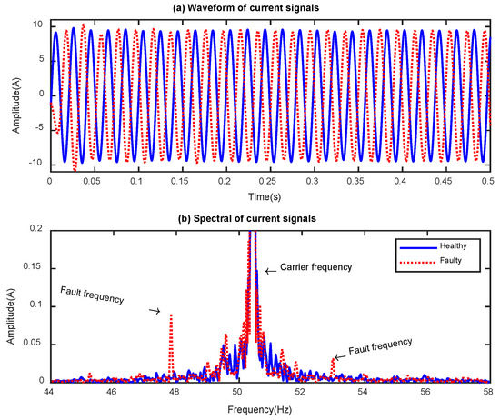
Figure 8.
Current from healthy and faulty IM.
However, the fault frequency will be varied along with the main supply frequency () and slips () according to Equation (1) in Section 2.1, and the slips () are sensitive to the operating loads. Based on the measured current signals in the tests, the main supply frequencies () for different operating conditions and fault cases are calculated and listed in Table 5. It shows that the main supply frequency is around 50 Hz under different operating conditions, but it is slightly varied and increases along with the increases of operating loads. Hence, the slip and fault frequency will be also changed based on the calculations using Equations (1) and (2) in Section 2.1. The slips and the BRB fault frequency in the experiment study are calculated and listed in Table 6 and Table 7, respectively.
Table 5.
Measured main supply frequency under different loads.
Table 6.
Slip under different loads.
Table 7.
Fault characteristic frequency under different loads.
Form Table 7, it can be seen that the values of the fault frequency are very small at lower operating loads (0% and 20% loads), and it is more easy to be submerged by the spectral leakage of the main supply frequency. Therefore, it is difficult to obtain accurate results using spectral analysis for BRB fault diagnosis, especially at lower operating loads.
Figure 9 displayed the spectrum of the measured current signal of the tested IM with 2 BRB fault under different loads. It found that the modulation sideband caused by the BRB fault cannot be identified obviously in Figure 9a (0% load), 9b (20% load) and 9c (40% load), as their amplitudes are very low and mainly submerged by the spectral leakage of the main supply frequency. Therefore, it is necessary to remove the main supply frequency components of the current signal for accurate fault feature extraction.
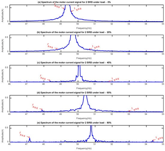
Figure 9.
Spectrum of the current signal for 2 BRB under different loads.
5.2. The TKEO Analysis Results
Based on the theoretical analysis in Section 2.2 and simulation evaluation in Section 3, TKEO is an effective method to remove the main supply component and separate the AM and FM components from the modulation sidebands for accurate fault identification. Therefore, the TKEO method is applied to analyze the measured motor current signals in order to validate the performance of the TKEO on the main supply frequency components’ suppression and modulation sidebands’ separation.
Figure 10 illustrates the TKEO spectrum of the measured signals from the IMs with BRB faults under different operating loads. It shows the distinctive peaks at the fault characteristic frequencies under all load conditions. Furthermore, the amplitude of the fault characteristic frequency shows good consistency that increases along with the increases of the operating loads. Moreover, it also shows excellence in noise deduction for the enhancement of fault frequency components without interference components.
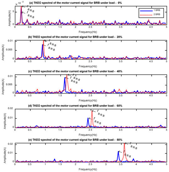
Figure 10.
TKEO spectrum of the motor current signal for BRBs under different loads.
Then, the amplitude values of the fault characteristic frequency are extracted as the fault detector for the BRB fault classification based on the TKEO spectrum, and the classification result is shown in Figure 11a. It can be seen that the BRB fault severities can be distinguished effectively for most of the operating loads except for the unload condition (0% load) and provide consistent trends for BRB fault diagnostics.
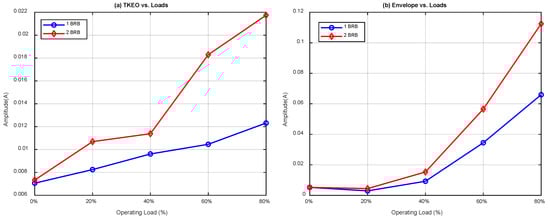
Figure 11.
Fault detector for BRB under different loads: (a) TKEO analysis; (b) Envelope analysis.
For comparison analysis, the envelope analysis is applied to demodulate the modulation sideband components from the measured motor current signals for BRB fault detection. The envelope spectrum of the motor current signals measured from the IMs with BRB faults under different operating loads is illustrated in Figure 12. It demonstrates that the fault characteristic frequency can be highlighted under higher loads, such as 40%, 60%, and 80% loads, but it is difficult to extract the fault characteristic frequency in the lower loads (0% and 20% loads), as the fault characteristic frequencies are polluted by the strong noise and interference components. Moreover, there are strong interference frequency components at lower frequencies for all the load conditions as marked with a square box in Figure 12, such as around 0.5 Hz under 20% load, around 0.3 Hz under 40% load, and around 0.8 Hz under 60% load. The interference frequency components will affect the accuracy of the fault characteristic frequency identification and fault diagnosis results.
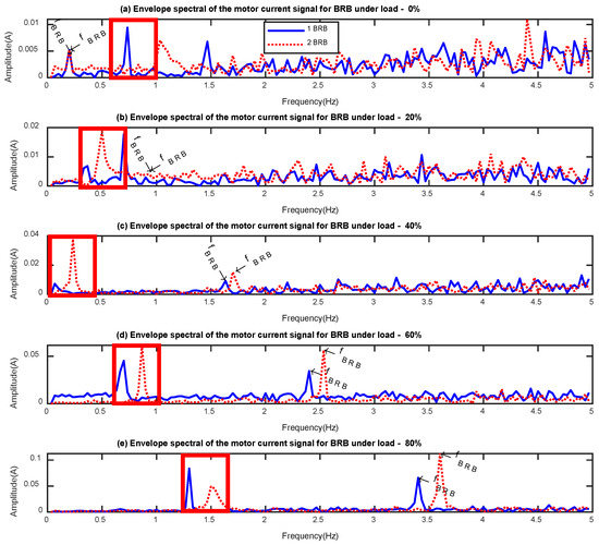
Figure 12.
Envelope spectrum of the motor current signal for BRB under different loads.
Then, the amplitude values of the identified fault characteristic frequency using envelope analysis are extracted as the fault detector for the BRB fault classification, as shown in Figure 11b. The classification results presented in Figure 11b show that it can provide consistent trends for BRB fault detection, but cannot distinguish the fault severities under low operating loads, especially for loads of 0% and 20%.
Furthermore, the instantaneous amplitude and frequency demodulation of the measured motor current signals can be achieved using the TKEO method. The separation of the AM and FM components from the modulation sideband for the classification of BRB faults is illustrated in Figure 13a,b, respectively. It can be seen from Figure 13a that the classification results based on IA analysis using TKEO is similar to that using envelope analysis as shown in Figure 11b, which obtains the similar conclusion of the simulation study. They can provide a consistency trend for BRB fault diagnosis, but cannot distinguish the fault severities very well for low load conditions. Through analyzing the classification result presented in Figure 13b that is based on IF analysis using the TKEO method, the BRB fault severities can be detected accurately and distinguished effectively, especially for the low loads (0% and 20% loads). Moreover, it is obvious that the feature values of IA analysis using the TKEO method are increased along with the increases of operating loads, as shown in Figure 13a. In contrast, the feature values of IF analysis using TKEO are decreased along with the increase of operating loads. This demonstrates that the AM is the main modulation component under high operating loads, while the FM is the main modulation component under low operating loads.
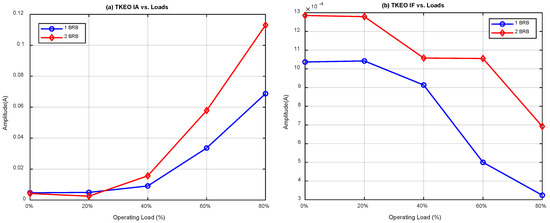
Figure 13.
Fault detector for BRB under different loads: (a) TKEO IA; (b) TKEO IF.
6. Conclusions
In this work, the TKEO method is proposed to demodulate the modulation components for accurate BRB fault feature identification and the fault severities classification of IMs based on MCSA. By applying the proposed method, the main supply component of the motor current signal is removed, thereby reducing the adverse effect of its spectral leakage in the accurate fault feature extraction, especially for the fault diagnosis when the IMs are operating under low load with low slip. Based on the comparison analysis, the proposed method can provide more accurate spectrum with lower noise and interference components for fault characteristic frequency identification than the envelope analysis. Moreover, the AM and FM components from the modulation sidebands can be separated effectively from the IA and IF demodulation using the TKEO method. The fault diagnostic and classification results based on IA analysis obtained the same conclusion of the envelope analysis, and the fault diagnostic and classification results based on IF analysis can distinguish the fault severities very well for all the load conditions, thus improving the performance of fault diagnosis based on MCSA when the IM is working at very low load. The proposed method has been validated in simulation and experimental studies that tested the IMs with different BRB fault severities. Although the proposed method in this work detected the BRB faults of the IM operating at constant speeds, it can be extended to diagnose the IM under transient operating conditions with other fault types.
Author Contributions
Conceptualization, F.G. and A.B.; methodology, D.Z.; validation, H.L., D.Z., and Z.W.; formal analysis, H.L. and Z.W.; investigation, D.Z.; resources, F.G.; data curation, F.G.; writing—original draft preparation, H.L.; writing—review and editing, D.Z.; supervision, F.G.; project administration, D.Z. and F.G.; funding acquisition, D.Z.
Funding
This research was funded by the National Natural Science Foundation of China, grant number 51605133, 51705127 and the Hebei Provence Science and Technology Support Program, grant number 17394303D.
Conflicts of Interest
The authors declare no conflict of interest.
References
- Choudhary, A.; Goyal, D.; Shimi, S.L.; Akula, A. Condition monitoring and fault diagnosis of induction motors: A review. Arch. Comput. Methods Eng. 2019, 26, 1221–1238. [Google Scholar] [CrossRef]
- Mehrjou, M.R.; Mariun, N.; Marhaban, M.H.; Misron, N. Rotor fault condition monitoring techniques for squirrel-cage induction machine—A review. Mech. Syst. Signal Process. 2011, 25, 2827–2848. [Google Scholar] [CrossRef]
- Zolfaghari, S.; Noor, S.B.M.; Rezazadeh Mehrjou, M.; Marhaban, M.H.; Mariun, N. Broken rotor bar fault detection and classification using wavelet packet signature analysis based on fourier transform and multi-layer perceptron neural network. Appl. Sci. 2018, 8, 25. [Google Scholar] [CrossRef]
- Wang, Z.; Yang, J.; Li, H.; Zhen, D.; Xu, Y.; Gu, F. Fault Identification of Broken Rotor Bars in Induction Motors Using an Improved Cyclic Modulation Spectral Analysis. Energies 2019, 12, 3279. [Google Scholar] [CrossRef]
- Zhen, D.; Wang, Z.; Li, H.; Zhang, H.; Yang, J.; Gu, F. An Improved Cyclic Modulation Spectral Analysis Based on the CWT and Its Application on Broken Rotor Bar Fault Diagnosis for Induction Motors. Appl. Sci. 2019, 9, 3902. [Google Scholar] [CrossRef]
- Aydin, I.; Karakose, M.; Akin, E. A New Method for Early Fault Detection and Diagnosis of Broken Rotor Bars. Energy Convers. Manag. 2011, 52, 1790–1799. [Google Scholar] [CrossRef]
- Ayhan, B.; Trussell, H.J.; Chow, M.Y.; Song, M.H. On the Use of a Lower Sampling Rate for Broken Rotor Bar Detection With DTFT and AR-Based Spectrum Methods. IEEE Trans. Ind. Electron. 2008, 55, 1421–1434. [Google Scholar] [CrossRef]
- Pineda-Sanchez, M.; Puche-Panadero, R.; Riera-Guasp, M.; Perez-Cruz, J.; Roger-Folch, J.; Pons-Llinares, J.; Climente-Alarcon, V.; Antonino-Daviu, J.A. Application of the Teager–Kaiser energy operator to the fault diagnosis of induction motors. IEEE Trans. Energy Convers. 2013, 28, 1036–1044. [Google Scholar] [CrossRef]
- Feng, Z.; Liang, M.; Chu, F. Recent Advances in time-frequency Analysis Methods for Machinery Fault Diagnosis: A Review with Application Examples. Mech. Syst. Signal Process. 2013, 38, 165–205. [Google Scholar] [CrossRef]
- Shi, P.; Chen, Z.; Vagapov, Y.; Zouaoui, Z. A New Diagnosis of Broken Rotor Bar Fault Extent in Three phase Squirrel Cage Induction Motor. Mech. Syst. Signal Process. 2014, 42, 388–403. [Google Scholar] [CrossRef]
- Ebrahimi, B.M.; Faiz, J.; Lotfi-fard, S.; Pillay, P. Novel Indices for Broken Rotor Bars Fault Diagnosis in Induction Motors Using Wavelet Transform. Mech. Syst. Signal Process. 2012, 30, 131–145. [Google Scholar] [CrossRef]
- Jimenez, G.A.; Munoz, A.O.; Duarte-Mermoud, M.A. Fault detection in induction motors using Hilbert and Wavelet transforms. Electr. Eng. 2007, 89, 205–220. [Google Scholar] [CrossRef]
- Gu, F.; Wang, T.; Alwodai, A.; Tian, X.; Shao, Y.; Ball, A.D. A new method of accurate broken rotor bar diagnosis based on modulation signal bispectrum analysis of motor current signals. Mech. Syst. Signal Process. 2015, 50, 400–413. [Google Scholar] [CrossRef]
- Sapena-Bano, A.; Pineda-Sanchez, M.; Puche-Panadero, R.; Martinez-Roman, J.; Kanović, Ž. Low-cost diagnosis of rotor asymmetries in induction machines working at a very low slip using the reduced envelope of the stator current. IEEE Trans. Energy Convers. 2015, 30, 1409–1419. [Google Scholar] [CrossRef]
- de Jesus Rangel-Magdaleno, J.; Peregrina-Barreto, H.; Ramirez-Cortes, J.M.; Gomez-Gil, P.; Morales-Caporal, R. FPGA-based broken bars detection on induction motors under different load using motor current signature analysis and mathematical morphology. IEEE Trans. Instrum. Meas. 2013, 63, 1032–1040. [Google Scholar] [CrossRef]
- Yang, X.; Ding, K.; He, G. Accurate separation of amplitude-modulation and phase-modulation signal and its application to gear fault diagnosis. J. Sound Vib. 2019, 452, 34–50. [Google Scholar] [CrossRef]
- Wang, D.; Zhao, X.; Kou, L.L.; Qin, Y.; Zhao, Y.; Tsui, K.L. A simple and fast guideline for generating enhanced/squared envelope spectra from spectral coherence for bearing fault diagnosis. Mech. Syst. Signal Process. 2019, 122, 754–768. [Google Scholar] [CrossRef]
- Trajin, B.; Chabert, M.; Regnier, J.; Faucher, J. Hilbert versus Concordia transform for three-phase machine stator current time-frequency monitoring. Mech. Syst. Signal Process 2019, 23, 2648–2657. [Google Scholar] [CrossRef]
- Puche-Panadero, R.; Pineda-Sanchez, M.; Riera-Guasp, M.; Roger-Folch, J.; Hurtado-Perez, E.; Perez-Cruz, J. Improved resolution of the MCSA method via Hilbert transform, enabling the diagnosis of rotor asymmetries at very low slip. IEEE Trans. Energy Convers. 2009, 24, 52–59. [Google Scholar] [CrossRef]
- Liu, Z.; Yin, X.; Zhang, Z.; Chen, D.; Chen, W. Online rotor mixed fault diagnosis way based on spectrum analysis of instantaneous power in squirrel cage induction motors. IEEE Trans. Energy Convers. 2004, 19, 485–490. [Google Scholar] [CrossRef]
- Antoniadou, I.; Manson, G.; Staszewski, W.J.; Barszcz, T.; Worden, K. A time–frequency analysis approach for condition monitoring of a wind turbine gearbox under varying load conditions. Mech. Syst. Signal Process. 2015, 64, 188–216. [Google Scholar] [CrossRef]
- Liang, M.; Bozchalooi, I.S. An energy operator approach to joint application of amplitude and frequency-demodulations for bearing fault detection. Mech. Syst. Signal Process. 2010, 24, 1473–1494. [Google Scholar] [CrossRef]
- Imaouchen, Y.; Kedadouche, M.; Alkama, R.; Thomas, M. A frequency-weighted energy operator and complementary ensemble empirical mode decomposition for bearing fault detection. Mech. Syst. Signal Process. 2017, 82, 103–116. [Google Scholar] [CrossRef]
- Zhao, H.; Li, L. Fault diagnosis of wind turbine bearing based on variational mode decomposition and Teager energy operator. IET Renew. Power Gener. 2017, 11, 453–460. [Google Scholar] [CrossRef]
- Khoshnami, A.; Sadeghkhani, I. Fault detection for PV systems using Teager–Kaiser energy operator. Electron. Lett. 2018, 54, 1342–1344. [Google Scholar] [CrossRef]
- Rodriguez, P.H.; Alonso, J.B.; Ferrer, M.A.; Travieso, C.M. Application of the Teager–Kaiser energy operator in bearing fault diagnosis. ISA Trans. 2013, 52, 278–284. [Google Scholar] [CrossRef] [PubMed]
- Liu, H.; Sun, Y.; Huang, J.; Hou, Z.; Wang, T. Inter-turn fault detection for the inverter-fed induction motor based on the Teager-Kaiser energy operation of switching voltage harmonics. In Proceedings of the 18th International Conference on Electrical Machines and Systems (ICEMS), Pattaya, Thailand, 25–28 October 2015; pp. 1214–1219. [Google Scholar]
- Teager, H. Some observations on oral air flow during phonation. IEEE Trans. Acoust. Speech Signal Process. 1980, 28, 599–601. [Google Scholar] [CrossRef]
- Islam, M.T.; Shahnaz, C.; Zhu, W.P.; Ahmad, M.O. Rayleigh modeling of teager energy operated perceptual wavelet packet coefficients for enhancing noisy speech. Speech Commun. 2017, 86, 64–74. [Google Scholar] [CrossRef]
- Kaiser, J.F. On a simple algorithm to calculate the ‘energy’ of a signal. In Proceedings of the International Conference on Acoustics, Speech, and Signal Processing, Albuquerque, NM, USA, 3–6 April 1990; pp. 381–384. [Google Scholar]
- Maragos, P.; Kaiser, J.F.; Quatieri, T.F. Energy separation in signal modulations with application to speech analysis. IEEE Trans. Signal Process. 1993, 41, 3024–3051. [Google Scholar] [CrossRef]
- Randall, R.B.; Smith, W.A. Uses and mis-uses of energy operators for machine diagnostics. Mech. Syst. Signal Process. 2019, 133, 106199. [Google Scholar] [CrossRef]
© 2019 by the authors. Licensee MDPI, Basel, Switzerland. This article is an open access article distributed under the terms and conditions of the Creative Commons Attribution (CC BY) license (http://creativecommons.org/licenses/by/4.0/).