Partial State-of-Charge Mitigation in Standalone Photovoltaic Hybrid Storage Systems

 , , , , and
Abstract
:1. Introduction
2. Specific Issues in Standalone Photovoltaic Systems
2.1. Incomplete Charge Process
2.2. Temperature Effect
3. HESS in Standalone PV Applications
3.1. System Parameters
- Pgen [W]: Peak PV power generation, i.e., the nominal PV cell power, provided by the manufacturer.
- Pcons [W]: Power consumption in the site. In this application, we assume it to be constant and known.
- GR: Generation Ratio. A dimensionless parameter that relates the PV installed peak power and the power consumption, see Equation (1). This value is closely linked to the average generation hours that the location of the installation performs. In this paper, this value remains fixed as the focus is on the storage system, but its impact will be analyzed in future research.
- EVRLA [Wh]: Installed energy in VRLA technology.
- ELiFePO4 [Wh]: Installed energy in LiFePO4 technology.
- Etot [Wh]: Maximum amount of energy that can be stored in the system, see Equation (2).
- Estored [Wh]: Total amount of energy that is stored in the system at a given time.
- A [h]: Maximum autonomy of the system. It is directly related to Etot and Pcons. This parameter makes possible to compare different installation sizes (in absolute power) with similar GR and A parameters.
- Pconv [W]: Maximum power that can flow through the converter. It depends on the specific converter, design and topology.
- Fhy: Hybrid factor. Defined as in Equation (4). A low Fhy assumes that most of the storage is based on VRLA technology, while a high Fhy means a higher presence of LiFePO4 batteries.
- State of Energy (%): In a HESS, each battery can have different nominal voltages, so talking in terms of charge and SoC has less sense than doing it in terms of energy. For this reason, State of Energy (SoE) is used as metric (5). This can also be defined for a simple ESS.
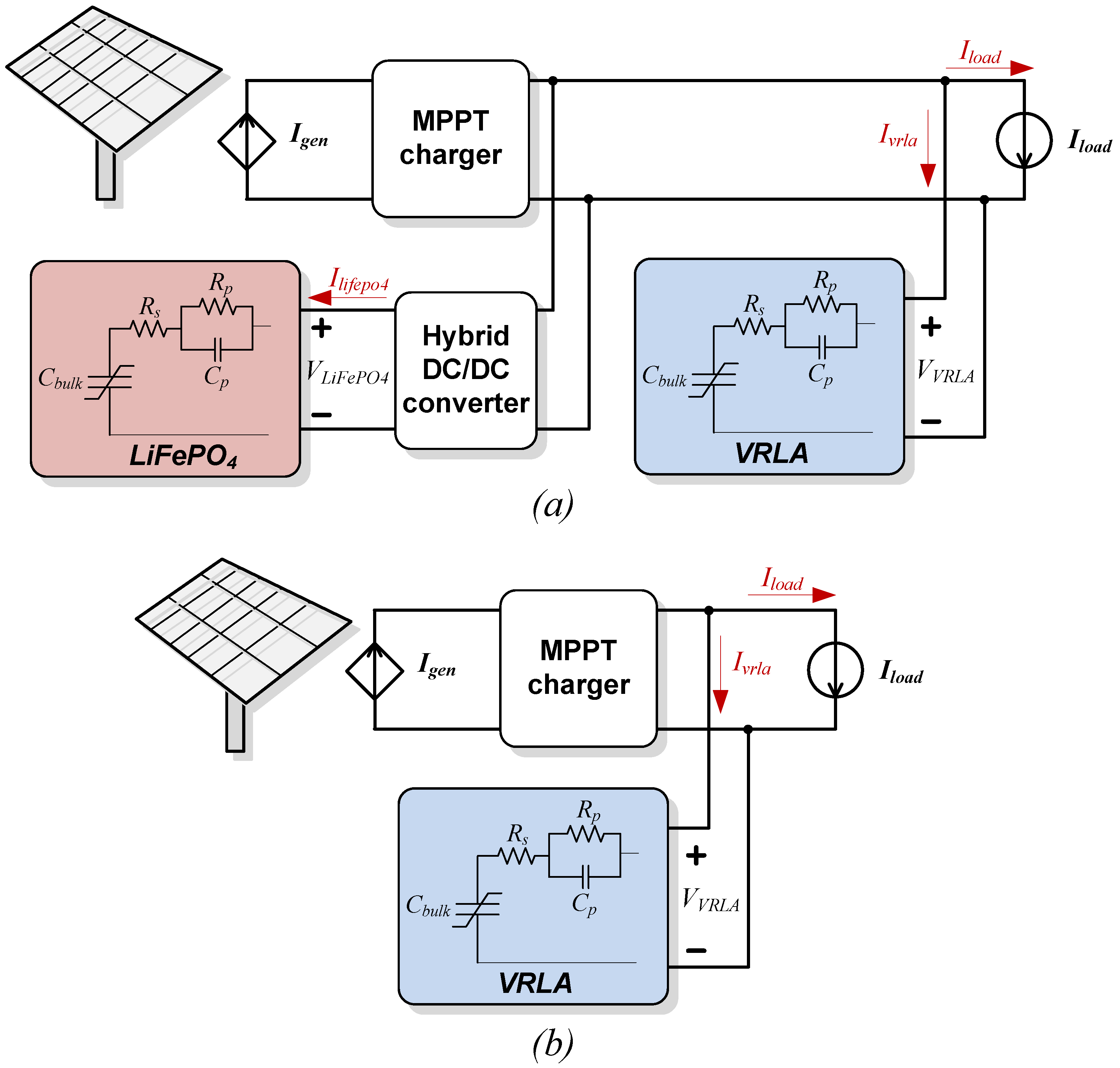
3.2. System Architecture
4. HESS Simulation
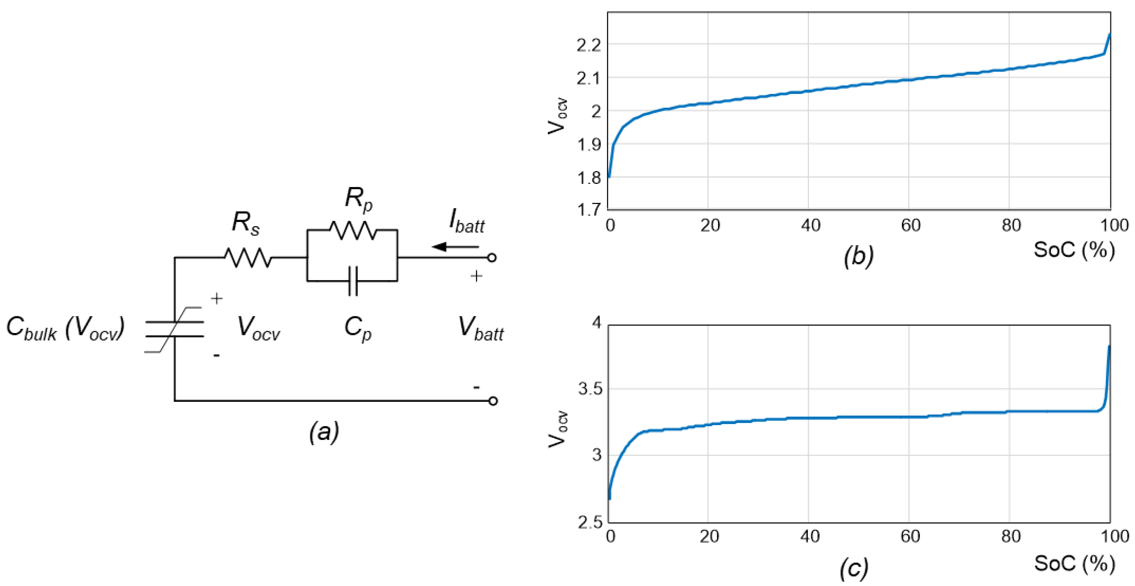
4.1. Battery Model
- Cbulk: non-linear bulk capacitance that models the battery storage capability. It depends on the battery internal voltage Vocv.
- Rs, Rp, Cp: parameters of the series impedance, considering a One Time-Constant (OTC) model.
- Vocv: Open Circuit Voltage of the battery. It is related to the internal electro-chemical state, and it can only be measured when the relaxation process has finished after a period of zero current (Vcp = 0 V).
- Vbatt: voltage measured at the battery terminals, whether there is current flowing or not.
- Ibatt: current that flows into the battery terminals.
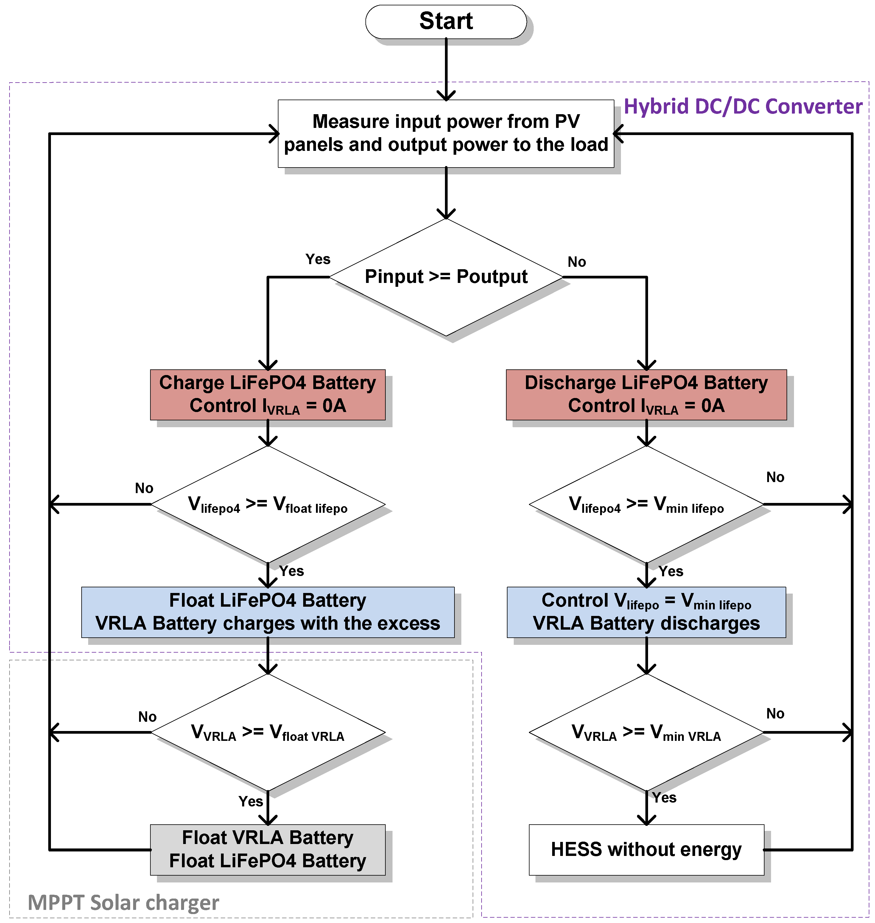
4.2. Simulation Approach
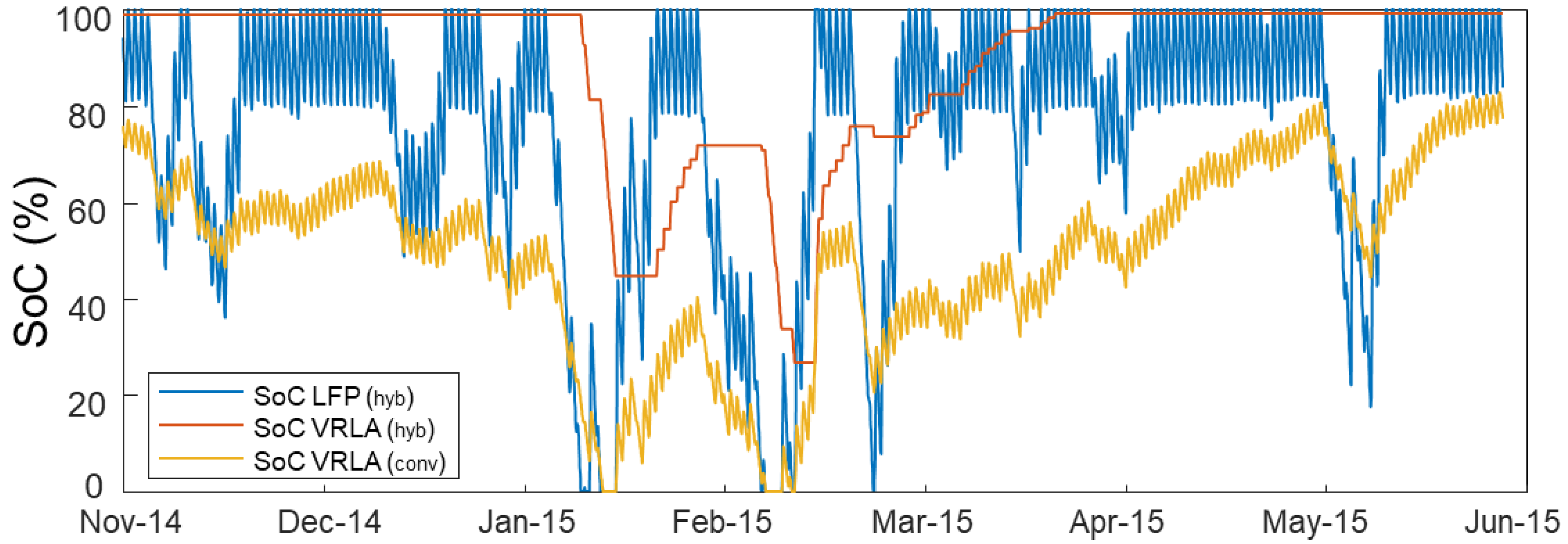
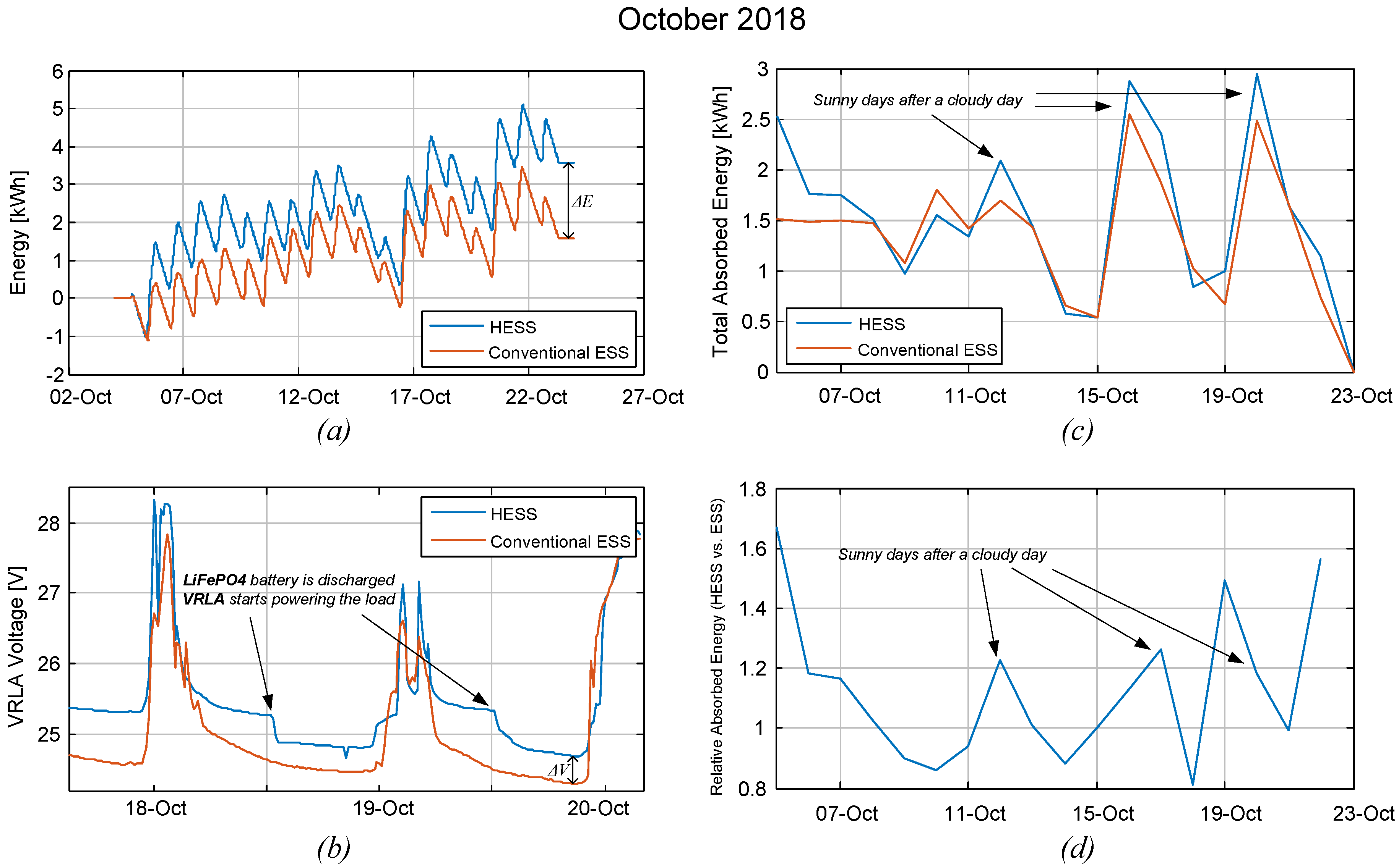
- Steady SoE improvement: the additional steady energy that the HESS maintains compared to the conventional ESS (expressed in percentage).
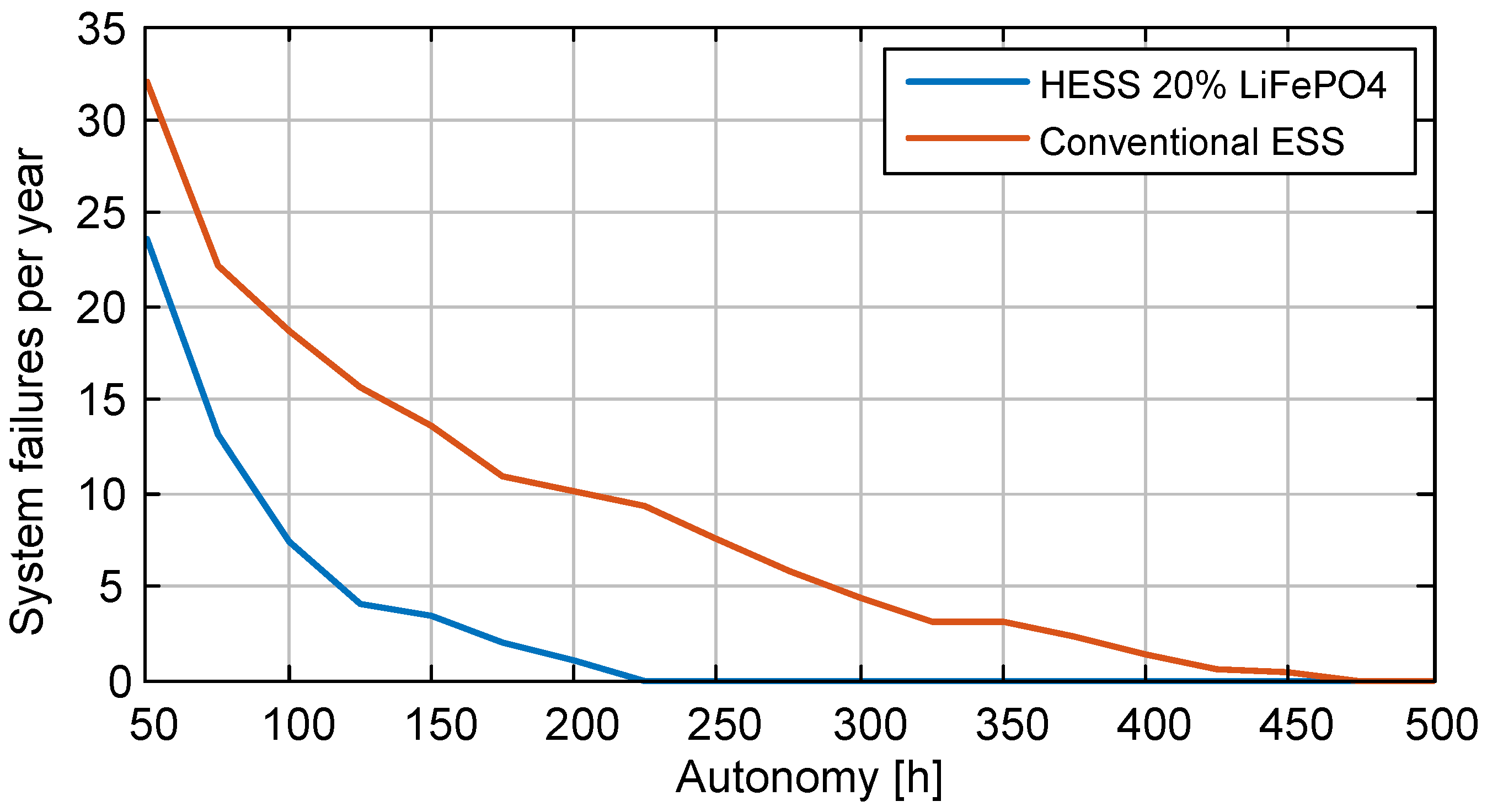
- Number of system failures (if any). Failures are caused by under-voltage situations on the VRLA battery.
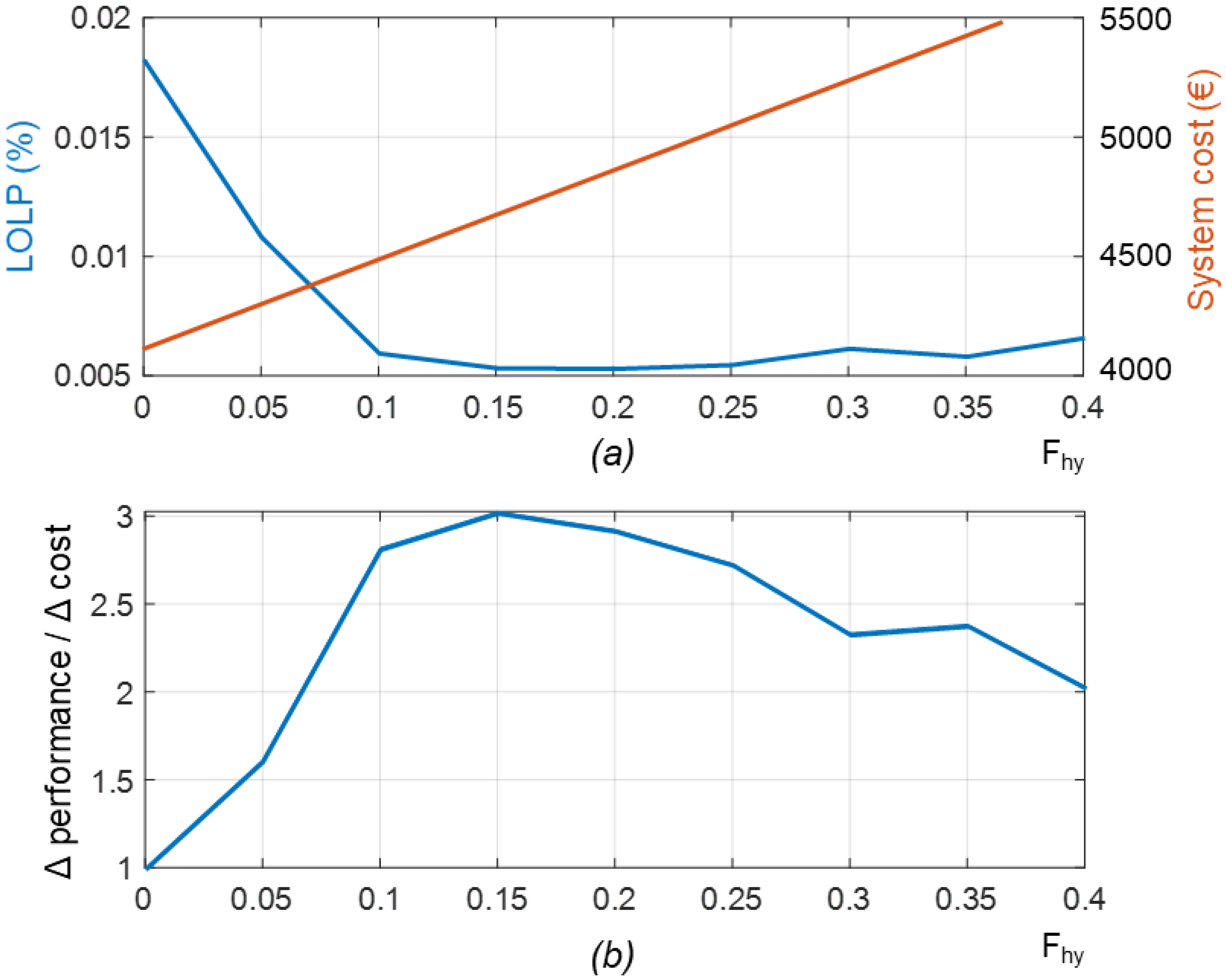
- Loss of Load Probability (LOLP). Fraction of time the system remains without energy, and therefore it cannot provide energy to the load.
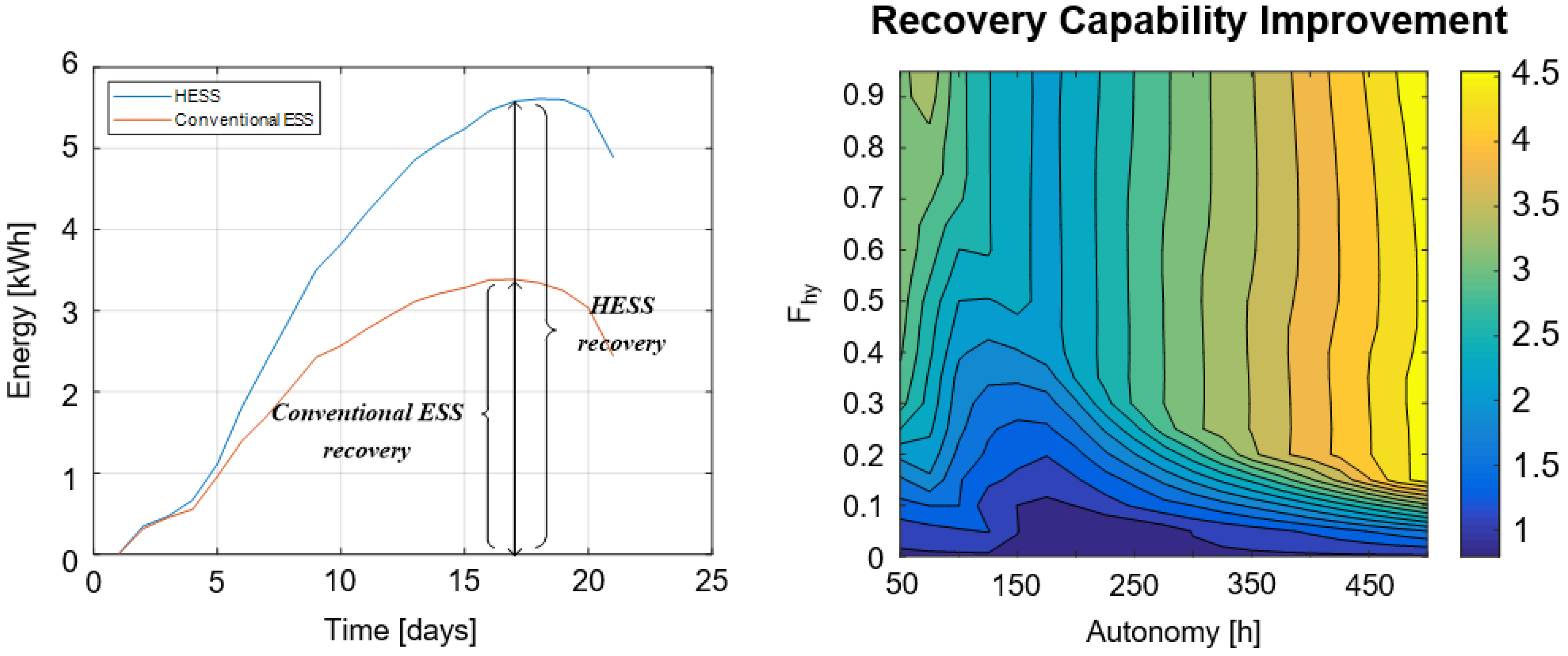
- Recovery improvement: the additional energy that the HESS harvests in a sunny period just after a system failure or low irradiation period, compared to the energy that the conventional ESS harvests.
4.3. Simulation Results
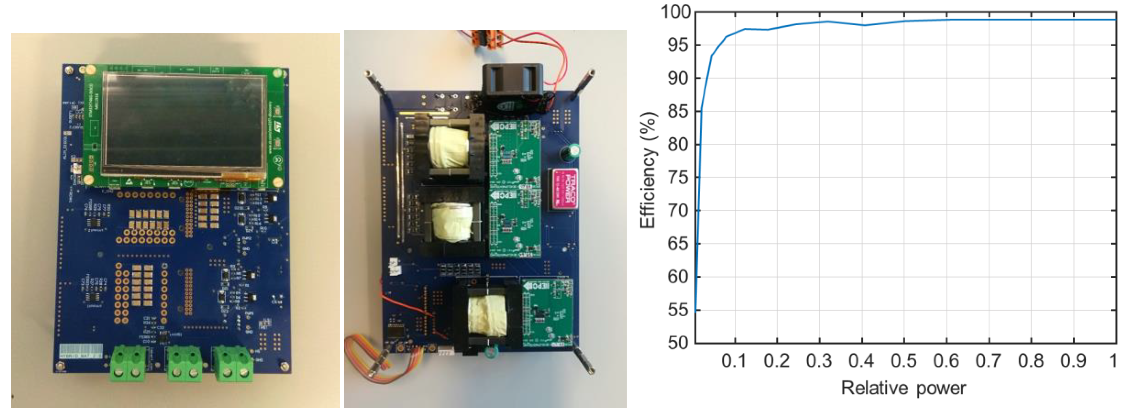
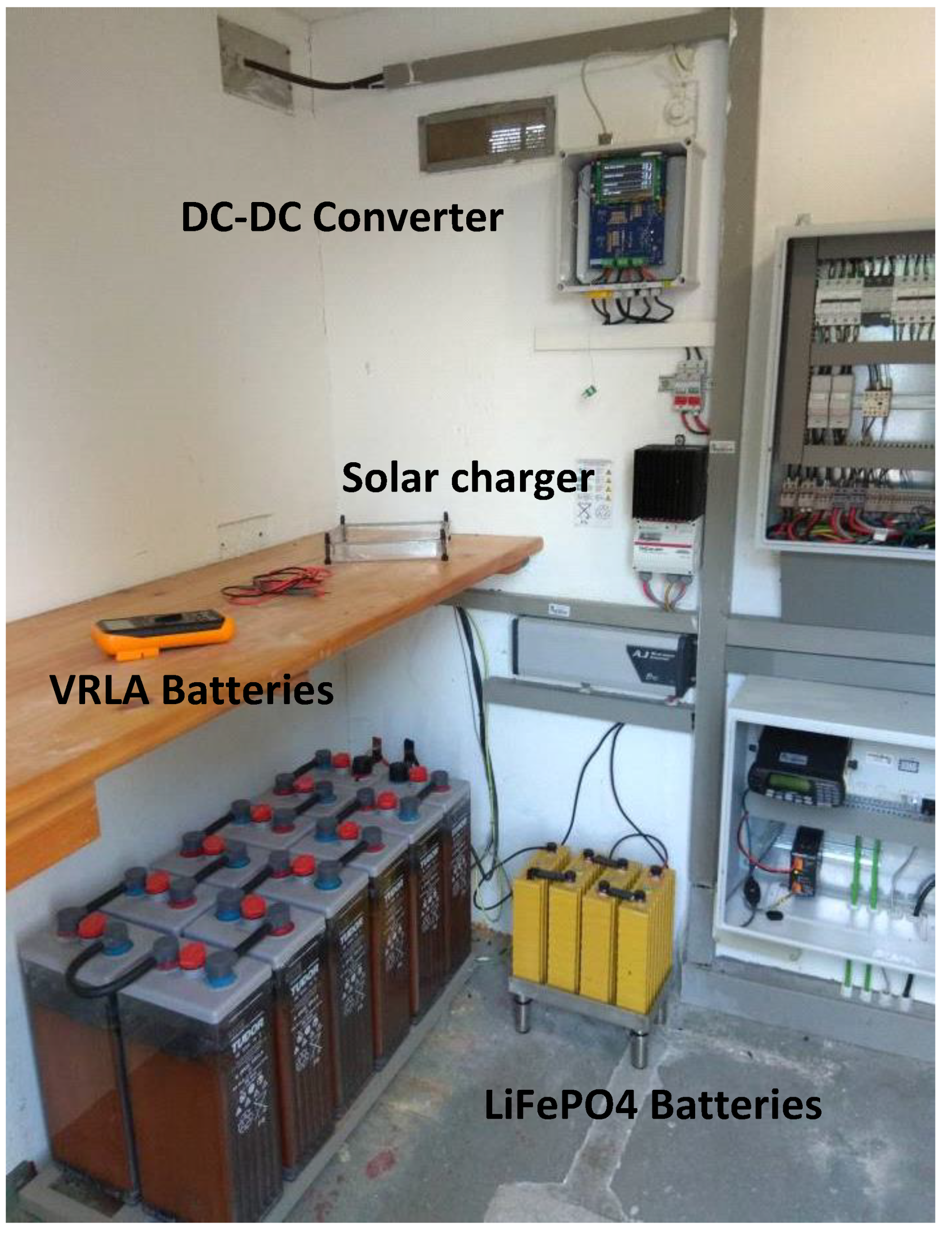
5. Experimental Results
6. Discussion
Author Contributions
Funding
Acknowledgments
Conflicts of Interest
References
- May, G.J. Recent progress in the development of VRLA batteries for the global telecom market. In Proceedings of the Intelec’96—International Telecommunications Energy Conference, Boston, MA, USA, 6–10 October 1996; IEEE: Piscataway, NJ, USA, 1996; pp. 168–171. [Google Scholar]
- Anbuky, A.H.; Pascoe, P.E. VRLA battery state-of-charge estimation in telecommunication power systems. IEEE Trans. Ind. Electron. 2000, 47, 565–573. [Google Scholar] [CrossRef]
- Karthigeyan, V.; Aswin, M.; Priyanka, L.; Sailesh, K.N.D.; Palanisamy, K. A comparative study of lithium ion (LFP) to lead acid (VRLA) battery for use in telecom power system. In Proceedings of the 2017 International Conference on Computation of Power, Energy Information and Commuincation (ICCPEIC), Melmaruvathur, India, 22–23 March 2017; IEEE: Piscataway, NJ, USA, 2017; pp. 742–748. [Google Scholar]
- Ragone, D.V. Review of Battery Systems for Electrically Powered Vehicles; SAE: Troy, MI, USA, 1968. [Google Scholar]
- Christen, T.; Carlen, M.W. Theory of Ragone plots. J. Power Sources 2000, 91, 210–216. [Google Scholar] [CrossRef]
- Oyarbide, E.; Elizondo, I.; Martinez-Iturbe, A.; Bernal, C.; Irisarri, J. Ultracapacitor-based plug & play energy-recovery system for elevator retrofit. In Proceedings of the 2011 IEEE International Symposium on Industrial Electronics, Gdansk, Poland, 27–30 June 2011; IEEE: Piscataway, NJ, USA, 2011; pp. 462–467. [Google Scholar]
- Anuphappharadorn, S.; Sukchai, S.; Sirisamphanwong, C.; Ketjoy, N. Comparison the Economic Analysis of the Battery between Lithium-ion and Lead-acid in PV Stand-alone Application. Energy Procedia 2014, 56, 352–358. [Google Scholar] [CrossRef]
- Podder, S.; Khan, M.Z.R. Comparison of lead acid and Li-ion battery in solar home system of Bangladesh. In Proceedings of the 2016 5th International Conference on Informatics, Electronics and Vision (ICIEV), Dhaka, Bangladesh, 13–14 May 2016; IEEE: Piscataway, NJ, USA, 2016; pp. 434–438. [Google Scholar]
- Wang, X.; Adelmann, P.; Reindl, T. Use of LiFePO4 Batteries in Stand-Alone Solar System. Energy Procedia 2012, 25, 135–140. [Google Scholar] [CrossRef]
- Jousse, J.; Lemaire, E.; Ginot, N.; Batard, C.; Diouris, J.-F. Assessment of lithium ion LiFePO4 cells usage in photovoltaic standalone systems. In Proceedings of the IECON 2013—39th Annual Conference of the IEEE Industrial Electronics Society, Vienna, Austria, 10–13 November 2013; IEEE: Piscataway, NJ, USA, 2013; pp. 1530–1535. [Google Scholar]
- Kim, Y.; Koh, J.; Xie, Q.; Wang, Y.; Chang, N.; Pedram, M. A scalable and flexible hybrid energy storage system design and implementation. J. Power Sources 2014, 255, 410–422. [Google Scholar] [CrossRef]
- Chemali, E.; McCurlie, L.; Howey, B.; Stiene, T.; Rahman, M.M.; Preindl, M.; Ahmed, R.; Emadi, A. Minimizing battery wear in a hybrid energy storage system using a linear quadratic regulator. In Proceedings of the IECON 2015—41st Annual Conference of the IEEE Industrial Electronics Society, Yokohama, Japan, 9–12 November 2015; IEEE: Piscataway, NJ, USA, 2015; pp. 3265–3270. [Google Scholar]
- Bocklisch, T. Hybrid Energy Storage Systems for Renewable Energy Applications. Energy Procedia 2015, 73, 103–111. [Google Scholar] [CrossRef]
- Merei, G.; Berger, C.; Sauer, D.U. Optimization of an off-grid hybrid PV–Wind–Diesel system with different battery technologies using genetic algorithm. Sol. Energy 2013, 97, 460–473. [Google Scholar] [CrossRef]
- Rahe, C. Lead-acid Batteries and Lithium-ion Batteries in parallel Strings for an Energy Storage System for a Clinic in Africa. In Proceedings of the 20th International Student Conference on Electrical Engineering, Prague, Czech Republic, 24 May 2016. [Google Scholar]
- Lukic, S.M.; Cao, J.; Bansal, R.C.; Rodriguez, F.; Emadi, A. Energy Storage Systems for Automotive Applications. IEEE Trans. Ind. Electron. 2008, 55, 2258–2267. [Google Scholar] [CrossRef]
- Cao, J.; Emadi, A. A New Battery/UltraCapacitor Hybrid Energy Storage System for Electric, Hybrid, and Plug-In Hybrid Electric Vehicles. IEEE Trans. Power Electron. 2012, 27, 122–132. [Google Scholar]
- Cao, J.; Schofield, N.; Emadi, A. Battery balancing methods: A comprehensive review. In Proceedings of the 2008 IEEE Vehicle Power and Propulsion Conference, Harbin, China, 3–5 September 2008; pp. 3–8. [Google Scholar]
- Lukic, S.M.; Wirasingha, S.G.; Rodriguez, F.; Cao, J.; Emadi, A. Power Management of an Ultracapacitor/Battery Hybrid Energy Storage System in an HEV. In Proceedings of the 2006 IEEE Vehicle Power and Propulsion Conference, Windsor, UK, 6–8 September 2006; IEEE: Piscataway, NJ, USA, 2006; pp. 1–6. [Google Scholar]
- Glavin, M.E.; Hurley, W.G. Ultracapacitor/battery hybrid for solar energy storage. In Proceedings of the 2007 42nd International Universities Power Engineering Conference, Brighton, UK, 4–6 September 2007; IEEE: Piscataway, NJ, USA, 2007; pp. 791–795. [Google Scholar]
- Kuperman, A.; Aharon, I. Battery–ultracapacitor hybrids for pulsed current loads: A review. Renew. Sustain. Energy Rev. 2011, 15, 981–992. [Google Scholar] [CrossRef]
- Adelmann, P.; Wolst, O.; Jun He, M.; Hamada, M.; Sengebush, F.; Li, Y.; Kufner, A. Topology and Control Strategy for Hybrid Storage Systems. U.S. Patent US20150270731A1, 24 September 2015. [Google Scholar]
- Garayalde, E.; Aizpuru, I.; Canales, J.M.; Sanz, I.; Bernal, C.; Oyarbide, E. Análisis Experimental del Efecto de la Temperatura y la Tensión de Carga para la Optimización Energética de Sistemas de Almacenamiento de Instalaciones Fotovoltaicas Aisladas. In Proceeding of the SAAEI, Valencia, Spain, 5–7 July 2017. [Google Scholar]
- Sanz-Gorrachategui, I.; Bernal, C.; Oyarbide, E.; Garayalde, E.; Aizpuru, I.; Canales, J.M.; Bono-Nuez, A. New battery model considering thermal transport and partial charge stationary effects in photovoltaic off-grid applications. J. Power Sources 2018, 378, 311–321. [Google Scholar] [CrossRef]
- Swingler, A.; Colgate, G. 12 Years of Residential ‘Off-Grid’ PV Hybrid System Operation and Evolution in Nemiah Valley, Canada. In Proceedings of the 3rd International Hybrid Power Systems Workshop, Tenerife, Spain, 8–9 May 2018. [Google Scholar]
- Swingler, A.; Torrealba, J. Opportunity for Improving Lead-Acid Battery Management of Photovoltaic-Genset-Battery Hybrid Power Systems Based on Measured Field Data. Energies 2019, 12, 2237. [Google Scholar] [CrossRef]
- Moseley, P.T.; Rand, D.A. Partial State-of-Charge Duty: A Challenge but Not a Show-Stopper for Lead-Acid Batteries! ECS Trans. 2012, 41, 3–16. [Google Scholar]
- Jing, W.; Lai, C.H.; Ling, D.K.X.; Wong, W.S.H.; Wong, M.L.D. Battery lifetime enhancement via smart hybrid energy storage plug-in module in standalone photovoltaic power system. J. Energy Storage 2019, 21, 586–598. [Google Scholar] [CrossRef]
- GNB Industrial Power. Exide Technologies Handbook for Stationary Vented Lead-Acid Batteries Part 2: Installation, Commissioning and Operation; GNB Industrial Power: Büdingen, Germany, 2012; pp. 1–68. [Google Scholar]
- Albright, G.; Edie, J.; Al-Hallaj, S. A Comparison of Lead Acid to Lithium-ion in Stationary Storage Applications; AllCell Technologies LLC: Chicago, IL, USA, 2012; p. 14. [Google Scholar]
- Liu, J.; Gao, D.; Cao, J. Study on the effects of temperature on LiFePO4 battery life. In Proceedings of the 2012 IEEE Vehicle Power and Propulsion Conference, Seoul, Korea, 9–12 October 2012; IEEE: Piscataway, NJ, USA, 2012; pp. 1436–1440. [Google Scholar]
- Krieger, E.M.; Cannarella, J.; Arnold, C.B. A comparison of lead-acid and lithium-based battery behavior and capacity fade in off-grid renewable charging applications. Energy 2013, 60, 492–500. [Google Scholar] [CrossRef]
- Khatib, T.; Ibrahim, I.A.; Mohamed, A. A review on sizing methodologies of photovoltaic array and storage battery in a standalone photovoltaic system. Energy Convers. Manag. 2016, 120, 430–448. [Google Scholar] [CrossRef]
- Kebaïli, S.; Benalla, H. Optimal sizing of a stand-alone photovoltaic systems under various weather conditions in Algeria. Rev. Energies Renouvelab. 2015, 18, 179–191. [Google Scholar]
- Shen, W.X. Optimally sizing of solar array and battery in a standalone photovoltaic system in Malaysia. Renew. Energy 2009, 34, 348–352. [Google Scholar] [CrossRef]
- Jing, W.; Lai, C.H.; Wong, W.S.H.; Wong, M.L.D. A comprehensive study of battery-supercapacitor hybrid energy storage system for standalone PV power system in rural electrification. Appl. Energy 2018, 224, 340–356. [Google Scholar] [CrossRef]
- Kutkut, N.H.; Divan, D.M. Dynamic equalization techniques for series battery stacks. In Proceedings of the Proceedings of Intelec’96—International Telecommunications Energy Conference, Boston, MA, USA, 6–10 October 1996; IEEE: Piscataway, NJ, USA, 1996; pp. 514–521. [Google Scholar]
- Ceraolo, M. New dynamical models of lead-acid batteries. IEEE Trans. Power Syst. 2000, 15, 1184–1190. [Google Scholar] [CrossRef]
- Barsali, S.; Ceraolo, M. Dynamical Models of Lead-Acid Batteries: Implementation Issues. IEEE Trans. Energy Convers. 2002, 17, 16–23. [Google Scholar] [CrossRef]
- Pascoe, P.E.; Anbuky, A.H. VRLA battery discharge reserve time estimation. IEEE Trans. Power Electron. 2004, 19, 1515–1522. [Google Scholar] [CrossRef]
- Chen, M.; Rincon-Mora, G.A. Accurate Electrical Battery Model Capable of Predicting Runtime and I–V Performance. IEEE Trans. Energy Convers. 2006, 21, 504–511. [Google Scholar] [CrossRef]
- Coleman, M.; Hurley, W.G.; Chin Kwan Lee, C.K. An Improved Battery Characterization Method Using a Two-Pulse Load Test. IEEE Trans. Energy Convers. 2008, 23, 708–713. [Google Scholar] [CrossRef]
- Coleman, M.; Lee, C.K.; Zhu, C.; Hurley, W.G. State-of-charge determination from EMF voltage estimation: Using impedance, terminal voltage, and current for lead-acid and lithium-ion batteries. IEEE Trans. Ind. Electron. 2007, 54, 2550–2557. [Google Scholar] [CrossRef]
- Günther, M.; Feldmann, U.; ter Maten, J. Modelling and Discretization of Circuit Problems. Handb. Numer. Anal. 2005, 13, 523–659. [Google Scholar]
- Macdonald, J.R.; Brachman, M.K. The Charging and Discharging of Nonlinear Capacitors. Proc. IRE 1955, 43, 71–78. [Google Scholar] [CrossRef]
- Wyatt, J.L. Foundations of Nonlinear Network Theory; University of California: Berkeley, CA, USA, 1978. [Google Scholar]
- Muthuswamy, B.; Banerjee, S. Introduction to Nonlinear Circuits and Networks; Springer: Berkeley, CA, USA, 2018. [Google Scholar]
- Ansean, D.; Garcia, V.M.; Gonzalez, M.; Blanco-Viejo, C.; Viera, J.C.; Pulido, Y.F.; Sanchez, L. Lithium-Ion Battery Degradation Indicators Via Incremental Capacity Analysis. IEEE Trans. Ind. Appl. 2019, 55, 2992–3002. [Google Scholar] [CrossRef]
- Garcia, O.; Zumel, P.; de Castro, A.; Cobos, A. Automotive DC-DC bidirectional converter made with many interleaved buck stages. IEEE Trans. Power Electron. 2006, 21, 578–586. [Google Scholar] [CrossRef]


| Battery | Parameter | Value | Units |
|---|---|---|---|
| VRLA | Rs | 180 | mΩ |
| Rp | 50 | mΩ | |
| Cp | 9.4 e4 | F | |
| LiFePO4 | Rs | 50 | mΩ |
| Rp | 50 | mΩ | |
| Cp | 1.8 e4 | F |
| Element | Parameter | Value | Units |
|---|---|---|---|
| VRLA battery | Cnom | 420 | Ah |
| Vnom | 24 | V | |
| Model | Exide 6 OPzS 420 | - | |
| LiFePO4 battery | Cnom | 160 | Ah |
| Vnom | 12.8 | V | |
| Thunder Sky LYP160AHA(B) | - | ||
| Installation | DC Pcons | 84 | W |
| Solar Pgen | 700 | W | |
| Vnom | 24 | V | |
| Solar Charger | Model | Morningstar Tristar MPPT TS-45 | - |
© 2019 by the authors. Licensee MDPI, Basel, Switzerland. This article is an open access article distributed under the terms and conditions of the Creative Commons Attribution (CC BY) license (http://creativecommons.org/licenses/by/4.0/).
Share and Cite
Sanz-Gorrachategui, I.; Bernal Ruiz, C.; Oyarbide Usabiaga, E.; Bono Nuez, A.; Artal Sevil, S.J.; Garayalde Pérez, E.; Aizpuru Larrañaga, I.; Canales Segade, J.M. Partial State-of-Charge Mitigation in Standalone Photovoltaic Hybrid Storage Systems. Energies 2019, 12, 4393. https://doi.org/10.3390/en12224393
Sanz-Gorrachategui I, Bernal Ruiz C, Oyarbide Usabiaga E, Bono Nuez A, Artal Sevil SJ, Garayalde Pérez E, Aizpuru Larrañaga I, Canales Segade JM. Partial State-of-Charge Mitigation in Standalone Photovoltaic Hybrid Storage Systems. Energies. 2019; 12(22):4393. https://doi.org/10.3390/en12224393
Chicago/Turabian StyleSanz-Gorrachategui, Iván, Carlos Bernal Ruiz, Estanis Oyarbide Usabiaga, Antonio Bono Nuez, Sergio Jesús Artal Sevil, Erik Garayalde Pérez, Iosu Aizpuru Larrañaga, and Jose María Canales Segade. 2019. "Partial State-of-Charge Mitigation in Standalone Photovoltaic Hybrid Storage Systems" Energies 12, no. 22: 4393. https://doi.org/10.3390/en12224393
APA StyleSanz-Gorrachategui, I., Bernal Ruiz, C., Oyarbide Usabiaga, E., Bono Nuez, A., Artal Sevil, S. J., Garayalde Pérez, E., Aizpuru Larrañaga, I., & Canales Segade, J. M. (2019). Partial State-of-Charge Mitigation in Standalone Photovoltaic Hybrid Storage Systems. Energies, 12(22), 4393. https://doi.org/10.3390/en12224393