Article

Assessment of Iron Oxide (III)–Therminol 66 Nanofluid as a Novel Working Fluid in a Convective Radiator Heating System for Buildings

1
School of Mechanical Engineering, University of Adelaide, Adelaide, SA 5005, Australia
2
Department of Civil and Environmental Engineering, Florida International University, Miami, FL 33174, USA
3
ARC Research Hub for Graphene Enabled Industry Transformation, University of Adelaide, Adelaide, SA 5005, Australia
4
Sustainable Management of Natural Resources and Environment Research Group, Faculty of Environment and Labour Safety, Ton Duc Thang University, Ho Chi Minh City, Vietnam
5
Department of Mechanical and Materials Engineering, Florida International University, Miami, FL 33174, USA
*
Author to whom correspondence should be addressed.
Energies 2019, 12(22), 4327; https://doi.org/10.3390/en12224327
Submission received: 26 September 2019 / Revised: 4 November 2019 / Accepted: 8 November 2019 / Published: 13 November 2019
(This article belongs to the Section D1: Advanced Energy Materials)

Abstract

:
This work investigates the use of iron oxide (III)–therminol 66 oil-based nanosuspensions in a convective heating system with potential heating applications in the buildings sector. In an experimental study, characteristics of nanofluids were measured, including heat capacity, thermal conductivity, and density. The influences of mass flow rate and concentration of nanofluid on various parameters were quantified, such as pressure loss, friction coefficient, and heat transfer rate. For a concentration of 0.3 wt.%, the heat transfer increased by 46.3% and the pressure drop increased by 37.5%. The latter is due to the higher friction and viscosity of the bulk of the nanofluid. Although the pressure drop is higher, the thermo-hydraulic efficiency still increased by 19%. As a result, iron oxide (III)–therminol 66 presented reasonable thermal performance, higher heat transfer coefficient, and a lower pressure drop value (19% better performance in comparison with water) for the air–liquid convective system. Results also showed that for nanosuspensions at 0.3 wt.%, the friction factor of the system increased by 10% in comparison with the performance of the system with water.

1. Introduction

As the population of the world increases, the demands for efficient cooling and heating systems increases. Energy consumption increases in order to provide heating or cooling capacity for residential buildings have become a challenge. This is because fossil fuels are limited and the combustion of fossil fuel to produce energy is not sustainable, as it can pollute the environment and intensify global warming. Aside from this, the energy used in the industrial sector is supplied by fossil fuels, which increases environmental pollution. In-line with the limitation of fossil fuels, the price of these fuels varies due to their limited availability, war, and foreign policy. Collectively, it can be stated that in order to balance the demand for energy with the available resources and energy technologies, effort must be made by engineers, researchers, and scientists to identify alternatives and approaches for energy saving in all sectors, including in domestic buildings all over the world [1,2].
The high cost of energy production is a major challenge that pushes researchers forward to propose reliable solutions, with the view to address the above challenges [3,4]. Increasing the efficiency of thermal systems and process intensification are two areas of research, which are promising options that open new horizons for developing new efficient systems for cooling and heating systems. Since the introduction of nanofluids as advanced engineering fluids, much effort has been dedicated to applying this new type of coolant fluid in different thermal exchangers. Usually, a nanofluid is composed of water (an ordinary fluid) mixed with nano-sized solid particles with high conductivity, which improves the thermal conductance properties of the fluid. It has been shown that nanofluids can potentially have a higher heat transfer coefficient, which results in a decrease in the size of thermal energy systems [5,6,7,8]. Over two decades of research and development, various types of nanomaterials, such as Al2O3, CuO, MgO, and Fe3O4, and different kind of base fluids, such as water, engine oil, ethylene glycol, therminol 66, have been experimented on. As such, their physicochemical properties have been determined [9,10,11]. There are extensive studies proving that the thermal performance of heat transfer fluid is increased due to the phenomena occurring within the bulk of the nanofluid [12], such as Brownian motion and thermophoresis effects. These nanoscale phenomena can also improve the nanofluid’s properties, including heat capacity and the thermal conductivity, while also increasing the viscosity of the working fluid [13,14,15]. The enhancement in physical properties is the key parameter resulting in the improvement of the system’s efficiency. In another study, it was shown that by using nanofluid with 0.7 Vol.% of CuO nanoparticle, the consumption of water was decreased by 37.5%, which in turn decreased the size of the system by 55.7% [12], caused by higher heat transfer rate. Similar results have been obtained for systems such as microchannels, automotive radiators, convective heating systems, cavities, channels, heat exchangers, solar collectors, and porous media, showing the plausible application of nanofluids [13,14,15].
Recent studies have shown that convective systems provide about 50% of the heat supply to the domestic buildings sector [16]. Thus, economic design of convective system equipment can potentially reduce the fuel consumption rate by increasing thermal performance [17], although this is still not sufficient, as conventional working fluids have reached their limitations. For example, the thermal conductivity of water is 0.65 W/(mK), which is smaller than that measured for nanofluids (e.g., 0.79 W/(mK) for CuO/water nanofluid at 0.3 wt%). In another study, Kulkarni et al. [18] experimented with viscosity and heat transfer of CuO, SiO2, and Al2O3 nanoparticles dispersed in ethylene glycol (EG)–water in cold region convective systems. They considered nanofluids with concentrations of 0 to 6.12 vol.% and Reynolds numbers of 3000 to 12,000. They found that the use of nanofluids could decrease the flow rate and pumping power of the system. The use of nanofluids also reduced the size of the system. Park and Jung [19] evaluated the performance of carbon nanotubes (CNTs) dispersed in refrigerants to be utilized in a building chiller. The 1 vol.% concentration of CNTs was considered at heat flux values ranging between 7 and 80 kW/m2. The observations indicated that a higher heat transfer rate was achieved with a higher concentration of nanoparticles. For heat flux < 30 kW/m2, the increase was equal to +36.6%. Finally, they concluded that the use of CNTs in chillers improved the energy economy of the system. There are extensive studies similar to the aforementioned ones, which have been summarized in Table 1.
So far, most of the studies have focused on solutions for energy saving based around optimization of the design and configuration of the cooling and or heating systems [24], or on the type of the working fluid and the various materials used for thermal insulation, such as aerogel and plaster [25,26,27]. These materials have a long lifetime, and hence improve the economic viability of the thermal systems. Also, better energy saving may be obtained by applying advanced control equipment in heating or cooling systems. For example, Cockroft et al. [28] showed that using a zone control system can result in ~20% energy saving in buildings, in comparison with systems without any zone control option. Another plausible solution to achieve higher energy saving, a cleaner environment, and lower fluid consumption is to employ nanofluids in heating or cooling [29].
The stability of the used nanofluid is another key parameter that can affect its thermal properties. If the nanofluid is unstable, the value measured for the thermal conductivity and other thermo-physical properties might be larger than the real value [30]. Hence, extensive studies have been conducted to evaluate the stability of nanofluids using different experimental approaches. For example, in an experimental study, Colangelo et al. [31,32] developed a new approach to suppress the rate of sedimentation for the nanoparticles in a solar thermal collector. They demonstrated that with this approach the performance of the collector can be improved. In another study conducted by Choi et al. [33], the stability of an alumina and aluminum nitride nanofluid in oil was improved using oleic acid as a surfactant. They showed that despite plausible stability, if the quantity of the acid increases, it induces reverse micelles, which can promote fouling and scale formation in the system. Saeednia et al. [34] demonstrated that nanoparticles such as CuO can be partially stabilized in oil using a sonication device. Hence, they avoided the addition of surfactants to minimize the effects on other thermal properties of the nanofluid. In another attempt, Liu et al. improved the stability of carbon nanotubes in engine oil using an ultrasonic vibrator and avoided the addition of any surfactants [35]. While some researchers avoid using surfactants to enhance the stability of nanofluids, there are extensive studies in which surfactants have been identified as a key parameter for stabilizing nanofluids [30,36,37,38].
In light of the above literature, there are extensive studies in which an aqueous nanofluid (nanofluid dispersed in water or in a base fluid with a boiling temperature <150 °C) has been used as a heat transfer fluid in a system. Therefore, the application of working fluid is limited to a certain range of temperatures. Also, due to the evaporation of the base fluid, sedimentation and scale formation can occur in such systems. Thus, in the present work, we design and fabricate a convective air heating system with a radiator and use an electric fan to pass air through the fins of the radiator. An oil-based nanofluid is used in the radiator heating loop to promote the thermo-hydraulic index of the device. Therminol 66 was used as the base fluid, which offers good thermal features, such as a high boiling point and reasonably good thermal conductivity and heat capacity. Iron oxide III nanoparticles were used due to their good thermal characteristics. Iron oxide is a non-toxic and cost-effective nanomaterial that can be produced through different synthesis techniques. Also, to the best of the author’s knowledge, the thermal performance of therminol 66–iron oxide III nanofluid has not been investigated in house heating systems in the literature. The effect of inlet temperature, the nanofluid’s mass flow rate, and concentration on friction factor, heat transfer rate, and pressure loss are evaluated as well.

2. Materials and Methods

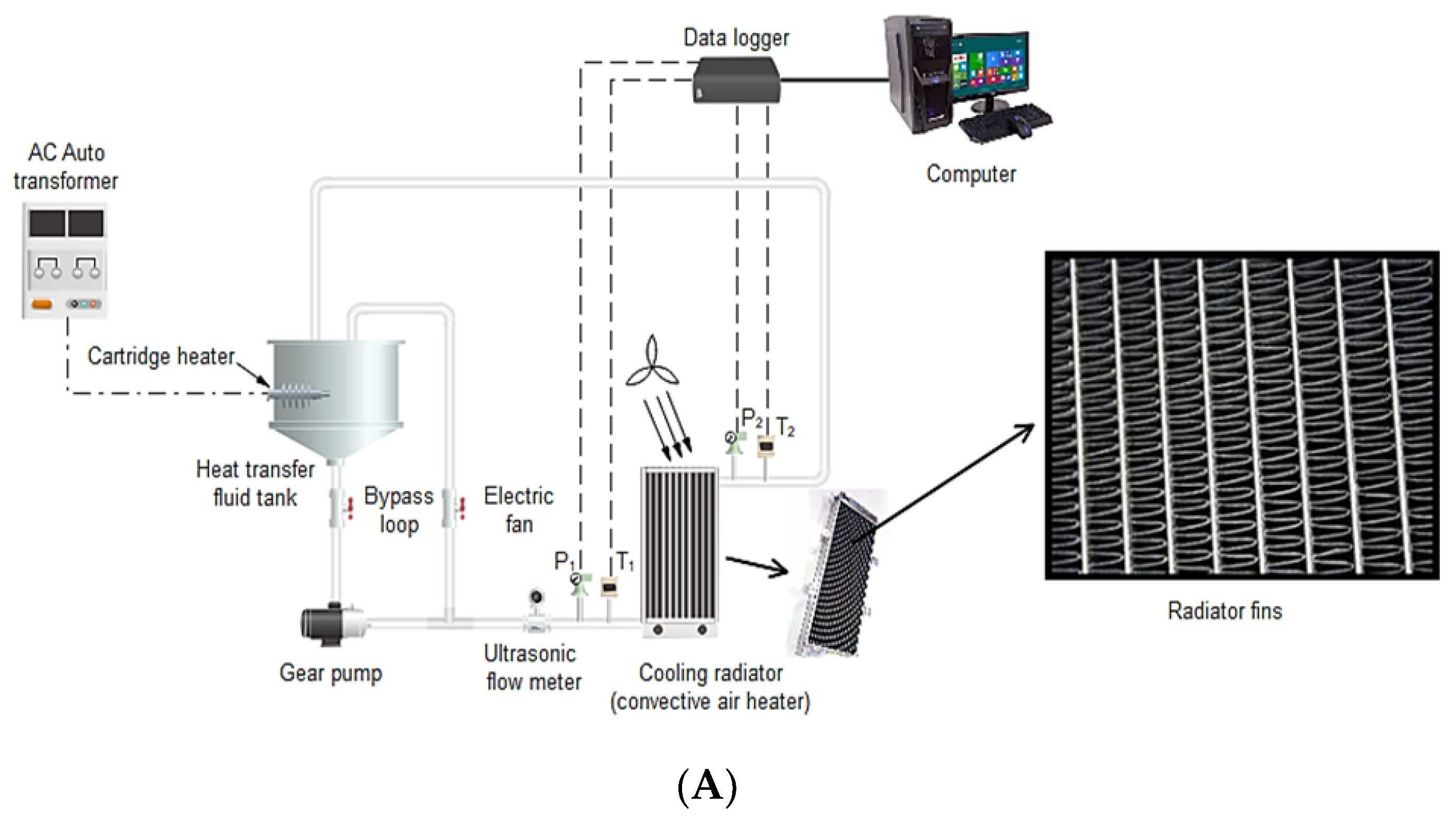
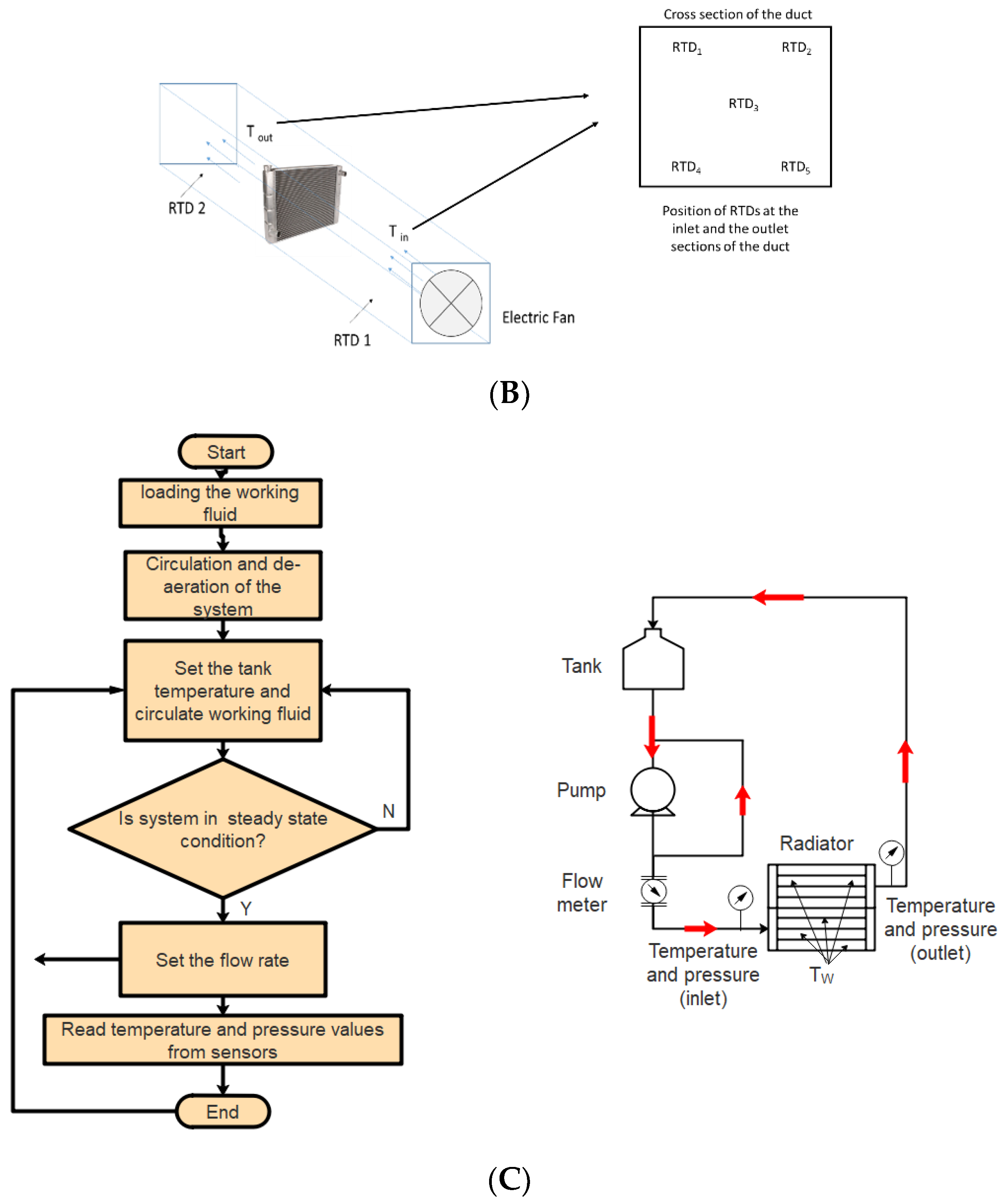
2.1. Experimental Setup

A schematic diagram of the experimental setup is depicted in Figure 1. The setup included a loop section for circulating the heat transfer fluid, a convective radiator, and the measurement instruments. The working fluid was loaded in a tank, which was heavily insulated with glass wool. An AC heater was installed inside the tank to provide the required heat to the working fluid and to maintain a uniform temperature in the tank. The heater was connected to an auto-transformer to adjust the voltage and consequently the heat applied to the tank. The coolant fluid is circulated from the tank to the radiator using a pump manufactured by DAB company with a maximum flow rate of Q = 8 lit/min. A bypass loop was designed to accurately control the flow rate of the working fluid. Two Omega pressure transducers were installed before and after the radiator. At the inlet and outlet channel, as shown in Figure 1B, five resistance temperature detector (RTDs) were installed at the inlet and outlet sides of the duct to read the inlet and outlet temperature of the air. The arithmetic average of the thermo-meter readings at each side was considered the inlet and outlet temperature. These instruments were connected to a high-frequency data logging system with the capability to record data at a frequency of 1 kHz. A Flownetix ultrasonic flow meter was used to record flow rate fluctuations in the loop. The convective radiator includes 45 straight tubes equipped with fins to improve the heat transfer performance from the working fluid towards the air. An electric fan was used to absorb the thermal energy from the radiator using air flow. A data logger was connected to a computer using a USB port to post-process the data. By using the overall heat transfer coefficient and the temperature and pressure readings, the friction factor and the loss of pressure due to the usage of nanofluids in the device were estimated. Notably, all the pipes, joints, and valves were heavily insulated with glass wool wrapped in plastic insulation material with thermal conductivity of 0.03 W/(mK), thermal resistance of 2.8 (m2K)/kW, density of 27.5 kg/m3, and thickness of 1.5 cm. Also, the thickness of the plastic wrap was 3 mm. This minimized the heat loss from the experimental setup to the environment.
The heat transfer tank was filled with the working fluid. Initially, the gear pump was switched on to circulate the working fluid inside the system. The whole test rig was allowed to run for about 1 h to de-aerate the piping systems and radiator. Then, the heater in the tank was switched on and temperature of the tank was set. The heater was connected to a proportion integration derivative controller (PID) to set the temperature of the tank to a set value. A PID controller prevents overshooting in the tank and provides a constant temperature. This provides a condition for a back-to-back comparison between the data collected at different operating conditions. When the temperature of the tank was constant, the required flow rate was adjusted using a bypass loop. At each flow rate, the inlet temperature, outlet temperature, inlet and outlet pressure, air temperature profile, and wall temperature of the radiator were recorded. Notably, an electric fan constantly operated to cool the radiator. The outlet of the radiator was then fed into the tank. A flow chart of the experimental procedure is given in Figure 1C.
Table 2 presents the specifications of the radiator used in the present research.

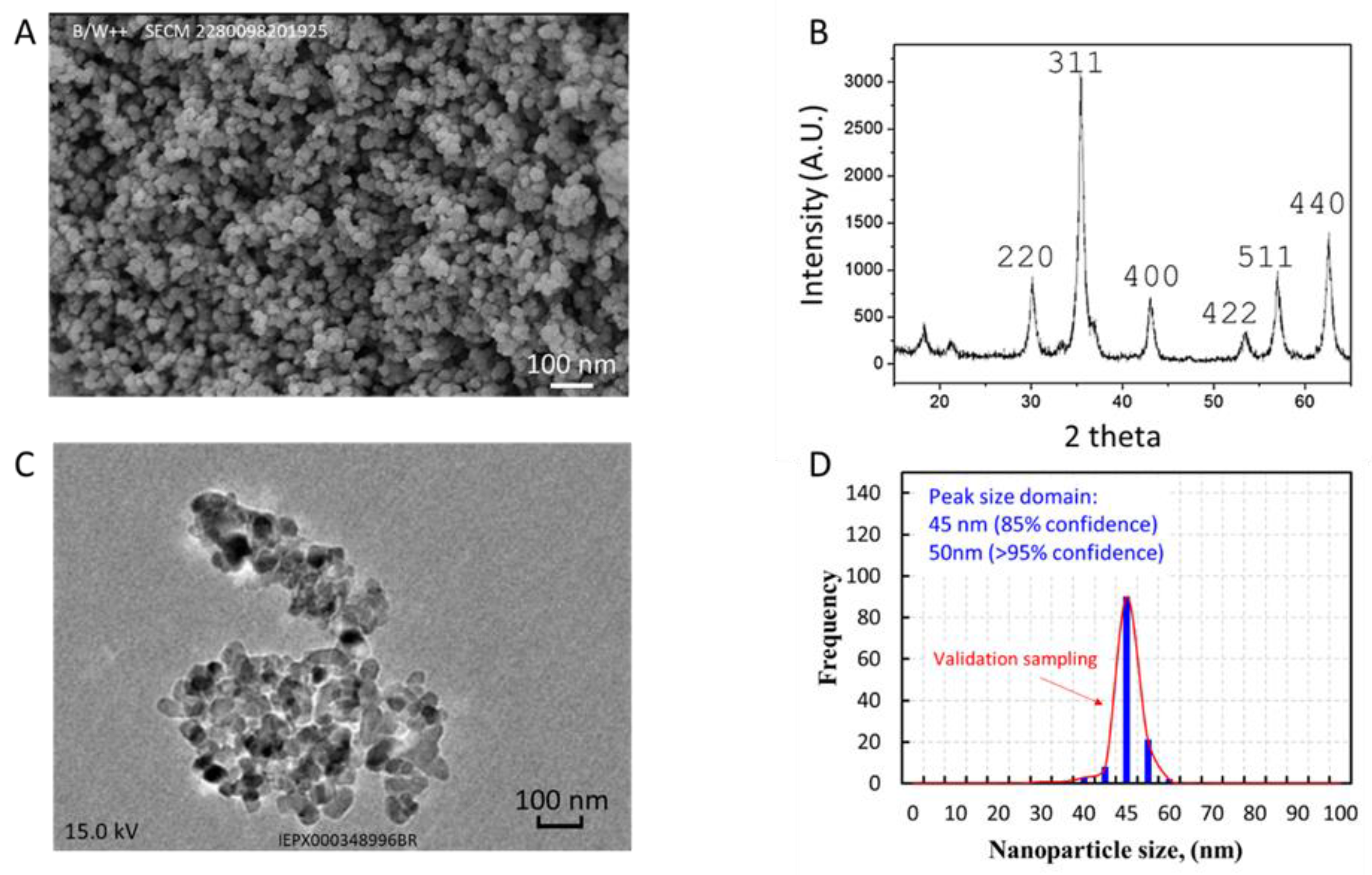
2.2. Preparation of the Nanofluids, Stability Analysis, and Characterization

A nanofluid based on oil was used to decrease the rate of evaporation of the working fluid, improving the thermal performance of the convective radiator by increasing the thermal capacity of the system and decreasing the rate of erosion and corrosion inside the radiator. Fe3O4 was purchased from USNANO Company. Tests were performed to ensure that the nanoparticles were of high quality. The following procedure was carried out to disperse the nanoparticles within therminol 66 as the base fluid: (1) initially, therminol 66 was heated up to 120 °C to evaporate any potential moisture trapped in the oil during the production stage; (2) the predetermined mass of the nanoparticles was dispersed in therminol 66 using a stirrer and ultrasonic homogenizer at 20 kHz and 300 Watt for 10 minutes. The concentrations of nanofluids by weight were 0.1%, 0.2, and 0.3%, without using any surfactants in order to avoid variations in the characteristics of the working fluid; (3) stability tests were conducted using time-settlement experiments, and it was identified that nanofluids can be stable for up to three weeks at pH 7.9, 8.0, and 8.1, with zeta potentials of −45 mV, −40 mV, and −45 mV for 0.1, 0.2, and 0.3 wt.%, respectively.
Figure 2 presents the results of the characterization tests conducted on Fe3O4 samples. In Figure 2A, the scanning electron microscopy (SEM) image shows that the morphology of the nanoparticles is uniform, and the nanoparticles are identical in size. Also, the nanoparticles have a mean diameter of 50 nm, which is equal to the size prescribed by the manufacturer. The X-ray pattern obtained via X-ray diffraction analysis (see Figure 2B) revealed that the structure of the samples includes Fe and O, and there are no peaks belonging to any other impurities. Hence, the thermal conductivity of the nanoparticles was not affected by any structural impurities. Likewise, the structure of Fe3O4 was identified, which was in agreement with the materials present in the compound based on the catalog. After dispersing the Fe3O4 nanoparticles in therminol 66, a transmission electron microscopic (TEM) photo was obtained for the nanofluid with a concentration of 0.1 wt.%, which is shown in Figure 2C. The picture shows the uniform dispersion of the nanoparticles in oil. A particle size count test was also carried out in order to make sure that the particle size in the catalogue was correct. Agglomeration of the nanoparticles is also undesirable, and a TEM photo can show that this has not occurred. However, there are some attractive forces that kept the particles close to each other. As shown in Figure 2, the nanoparticles are close to each other due to the attractive forces, while the boundary of each nanoparticle can clearly be distinguished within the image. This means that as soon as the nanosuspension is pumped into the loop, the nanoparticles are re-dispersed within the bulk of the base fluid. Agglomeration of the nanoparticle is undesirable because the particles create a porous cluster of nanoparticles. Such agglomeration can increase the apparent density of the nanoparticles, resulting in the deposition of the particles on the walls, inside the dead zones, and on the heating surfaces. Figure 2D shows that the nanoparticles have a dominant size of 45 to 50 nm. This is in agreement with the SEM and TEM results. To measure the nanoparticles size, a ZS zeta sizer manufactured by Malvern Company was employed, which can plot nanoparticle sizes from 0.5 nm to 5 µm using a distribution profile and digital light scattering. To measure the nanoparticles, a sample of nanoparticles was loaded into the cup and measurements were performed three times to ensure the repeatability of the results. An agreement of 1.3% was obtained, confirming the reliability of the measurements. It is worth noting that the measurements were conducted at room temperature and the samples were taken from the prepared nanofluids.

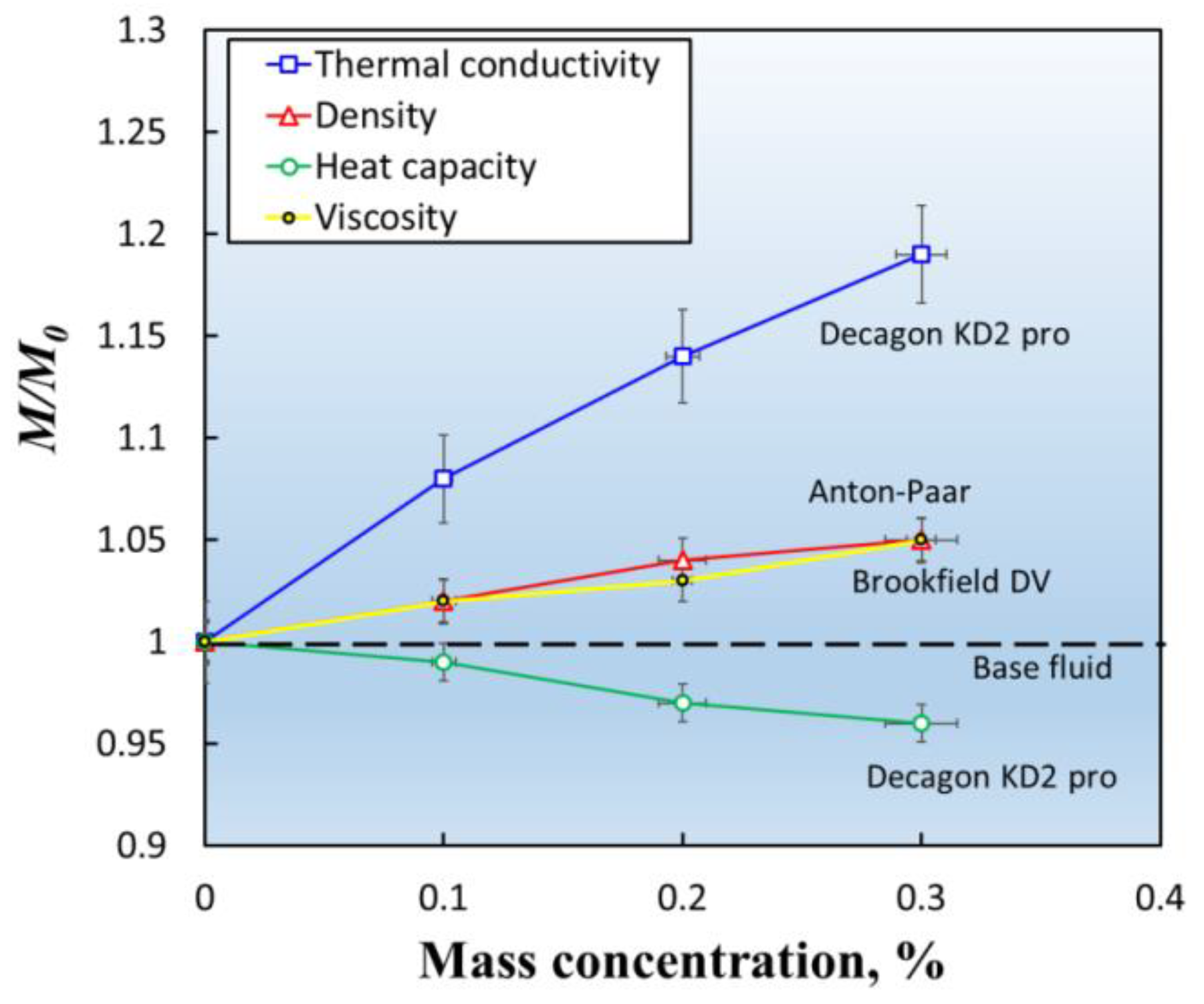
2.3. Nanofluids Properties

In order to obtain the nanofluids properties, density was measured with an Anton Paar density meter, while the heat capacity and thermal conductivity were measured with a Decagon KD2 pro instrument. The former has a measurement accuracy of ±1% of the reading value, while the latter has an accuracy of ±2% of the reading value. Figure 3 shows the nanofluid properties vs. mass concentration. M and M0 represent property values for the nanofluid and base fluid (therminol 66). Increasing the mass concentration of the nanofluid resulted in higher thermal conductivity. This is because the thermophoresis is amplified in the fluid bulk with greater Brownian motion of the particles. At 0.3 wt.% nanofluid, the thermal conductivity reached its maximum value, which was 20% higher than the base fluid. However, the heat capacity was reduced at this level because iron oxide has a lower heat capacity than therminol, and increasing the particle’s percentage reduces the heat capacity. For the nanofluid with 0.3 wt.% concentration, the heat capacity decreased by 4%. At higher nanofluid mass concentration, higher density was obtained, which was because of the larger density of iron oxide in comparison with therminol 66. Also, the viscosity of the nanosuspension was measured with a high-precision viscometer manufactured by Brookfield (DV model). As can be seen, the viscosity of therminol increased by adding iron oxide nanoparticles to the base fluid. The maximum augmentation of viscosity was observed at 0.3 wt.%, which was 5%. A linear trend between the viscosity of the nanosuspension and the mass concentration of the nanoparticles was observed.

2.4. Data Analysis and Uncertainty Quantification

The following equations were employed to calculate the heat transfer coefficient of the system:
For the liquid side:
Q = h A Δ T = h A ( T b T w )
Here, h is the convective heat transfer coefficient (HTC), A is the area of heat transfer, Tb and Tw are the bulk and wall temperatures. Tb is calculated with the following equation:
T b = T i n + T o u t 2
Here Tw is the arithmetic average of the five thermocouples installed on the wall of the convective radiator. The heat transfer from the air side can be calculated with the following equation:
Q = m C p ( T o u t T i n )
Merging Equations (1) and (2), the heat transfer coefficient can be obtained with the following equation:
h   o r   H T C = m C p ( T o u t T i n ) A ( T b T w )
Here, m is the mass of air, HTC is an acronym for Heat Transfer Coefficient, Tout and Tin are the outlet temperature and the inlet temperature of the air, respectively, both measured with two RTD thermo-meters. Here, h is the heat transfer coefficient, k is the thermal conductivity of the fabrication material of the radiator, and Dh is the hydraulic diameter. The friction factor was calculated by:
f = Δ P l D h 2 u 2 ρ
Here, ρ is the density of the working fluid and u is the velocity of the fluid measured with the flow meter.
The thermo-hydraulic index (THI) or η is calculated using Equation (6), as follows [39]:
η = ( N u n a n o f l u i d N u w a t e r ) × ( Δ P w a t e r Δ P n a n o f l u i d ) 1 3
In the above equation, the performance of the system is evaluated for the nanofluid against operation with water. The experimental uncertainty relative to the calculated uncertainty are shown in Table 3. The calculated uncertainty was estimated using the method introduced by Kline-McClintock [40].

3. Results

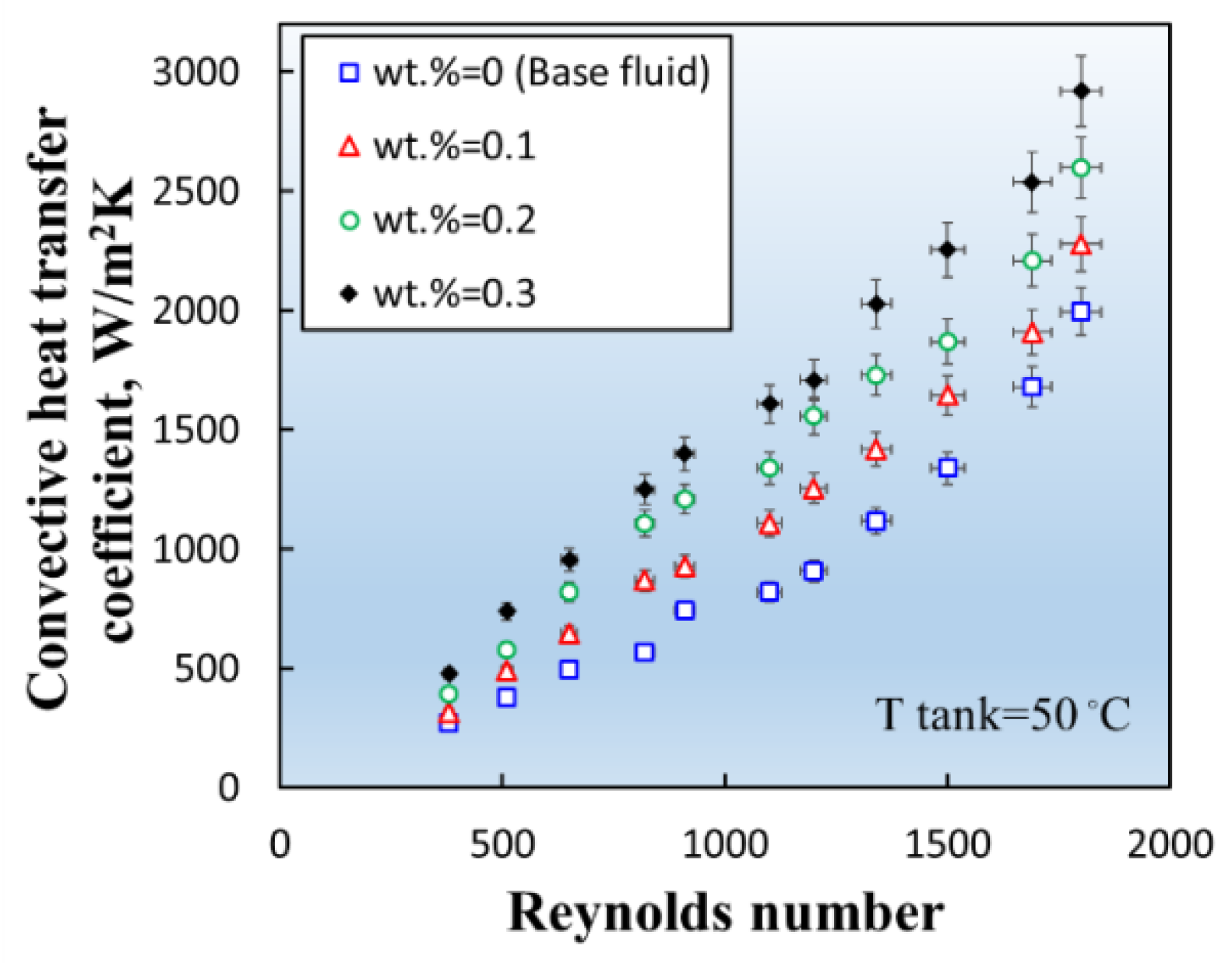
3.1. Convective Heat Transfer Coefficient

Figure 4 presents the variation of the convective heat transfer coefficient (HTC) with the Reynolds numbers for the base fluid and various nanofluids at 50 °C for the tank. The heat transfer coefficient is strongly influenced by Reynolds number, such that an increase in Reynolds number results in an increase in the HTC of the system. For example, for the base fluid, at Reynolds number of ~400, the HTC was 295, reaching to 910 and 1995 W/(m2K) at 1200 and 1800 Re, respectively. Higher system HTC can be obtained by increasing the mass concentration. At 1200 Re, the HTC for the nanofluid at 0.1 wt.% was 1255 W/(m2K), reaching 2280 W/(m2K) at 1800 Re. For the same Reynolds numbers, the HTC values were 1558 W/(m2K) and 2610 W/(m2K) at 0.2 wt.% and 1710 W/(m2K) and 2920 W/(m2K) at 0.3 wt.%. It is noted that the increase in heat transfer coefficient with Reynolds number was linear, and this trend was observed for all the concentrations and for all the tank temperatures. Notably, for any nanofluid concentration, the system’s HTC was higher than the base fluid. This was because of the Brownian motion of the particles, the thermophoresis influence, and the high thermal conductivity of the fluid. The largest heat transfer coefficient (2920 W/(m2K) was recorded for the nanofluid with the highest mass concentration (0.3 wt.%) and at the highest Reynolds number of 1800.

3.2. Pressure Drop

Figure 5 presents the effect of the Reynolds number on pressure drop for the base fluid and the nanofluids at tank temperature of 50 °C. Higher Re results in higher pressure loss. For the base fluid, at Re = 400, the pressure drop was 0.3 kPa, reaching 32 kPa at Re = 1800. Also, increasing the percentage of nanoparticles resulted in higher pressure loss. For example, at 1200 Re, the pressure drop value, ΔP were 14.8 kPa and 18.9 kPa at 0.1 wt.% and 0.3 wt.%, respectively. The iron oxide nanoparticles increased the fluid viscosity because of the interaction with the base fluid and the radiator walls. Higher ΔP resulted in higher pump power, which increased the operating costs of the device.

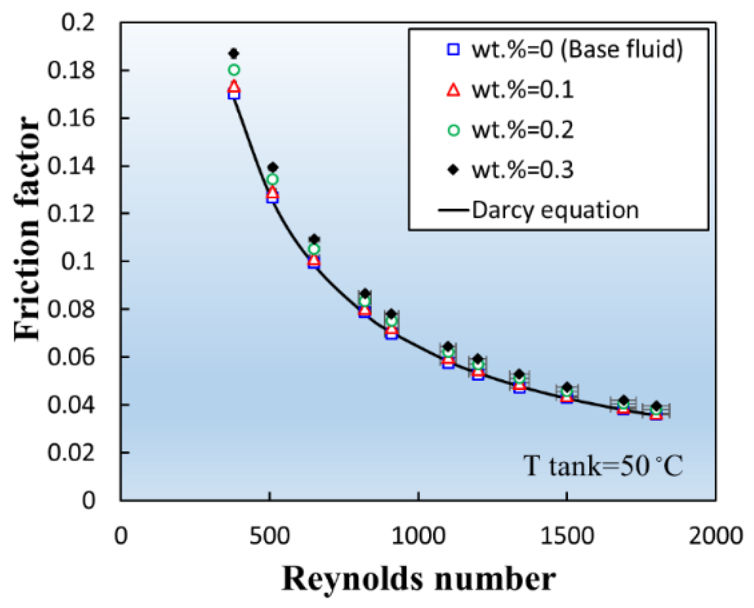
3.3. Friction Factor

Figure 6 presents the measured friction factor (f) for the nanofluids and the base fluid against the Darcy equation [41]. The friction factor vs. Re obeys Darcy’s law (higher Re results in lower f). Since the fluid flow was laminar, the trend was predictable by the equation of Darcy, however, for the nanofluids, because of higher viscosity with respect to the base fluid and additional friction within the base fluid due to the particle–particle, particle–base fluid, and particle–surface interactions, the friction factor was relatively higher than the base fluid. Results showed that in comparison with Darcy’s equation, we had a 3.1% increase in f for 0.1 wt.%, 7.2% increase for 0.2 wt.%, and 11.2% increase for 0.3 wt.%. For example, at 1800 Re, the friction factor for the base fluid was 0.0359, reaching 0.0366, 0.038, and 0.039 for nanofluids at 0.1, 0.2, and 0.3 wt.%, respectively.

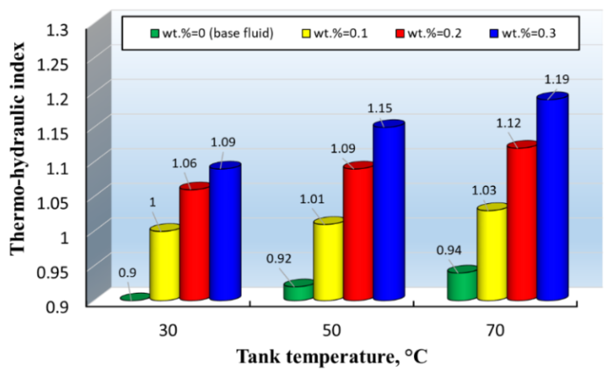
3.4. Temperature of the Tank

Figure 7 shows thermo-hydraulic index (THI) calculated with Equation (6), with the temperature of the tank shown for various nanofluids at 1800 Re. Water was selected as a reference case in order to compare with the works published in the literature [42,43]. At 30 °C, the base fluid (therminol 66) had the lowest THI, such that the performance of the system was 10% lower than water. Increasing the tank temperature resulted in slightly better system performance, but it was still less than water. For the nanofluid, the story was different, such that at 30 °C and 0.1 wt.%, the performance of the system was similar to water due to the pumping power required to overcome the pressure drop. However, for other nanofluids, the system’s thermal efficiency was higher than water, with a 19% increase with respect to water t 70 °C and 0.3 wt.%. This means that despite the pressure drop induced in the system by iron oxide nanoparticles, the increase in the HTC compensated for the pressure drop. This reveals the plausible application of iron oxide–therminol 66 nanofluid for laminar convective heating systems.

4. Conclusions

Here, we studied the thermo-hydraulic index of iron oxide nanoparticles mixed with therminol 66 base fluid in a convective radiator. The positive effect of iron oxide particles on the base fluid’s thermal conductivity was quantified. The radiator experienced a 46.3% increase in heat transfer vs. the base fluid, which was because of the thermophoresis influence, Brownian motion, and higher thermal conductivity with respect to therminol. In addition, the iron oxide nanoparticles improved the friction factor and pressure drop by 9.9% and 37.5% at 0.3 wt.%, respectively, which was due to the frictional forces induced in the system because of the nano-sized particles. Despite the higher ΔP and f, the device had a better thermo-hydraulic index (above 1), which means that the device was better than the system working that used water. The highest value of the index was 1.19, with respect to water at 70 °C. Overall, Fe3O4/therminol 66 showed good thermal performance in the convective radiator. However, this assessment was only for the laminar flow, and this must be re-assessed for systems in turbulent regimes, including the pressure drop and thermal characteristics of this nanofluid in those regimes.

Author Contributions

Conceptualization, M.M.S., A.D.B., M.R.S., and M.G.; methodology, M.R.S., A.D.B., and M.M.S.; formal analysis, M.M.S., A.D.B., and M.R.S.; investigation, M.M.S. and M.G.; writing—original draft preparation, M.M.S., A.S.L., M.R.S., M.G., and R.G.; writing—review and editing, M.A., R.G., M.M.S., A.D.B., Z.T., A.S.L., and C.-X.L.

Funding

This research received no external funding.

Acknowledgments

The authors of this work appreciate the Ton Duc Thang University for supporting the research. Adelaide microfluidics laboratory is also gratefully acknowledged.

Conflicts of Interest

The authors declare no conflict of interest.

References

  1. De Wilde, P.; Van Der Voorden, M. Providing computational support for the selection of energy saving building components. Energy Build. 2004, 36, 749–758. [Google Scholar] [CrossRef]
  2. Thormark, C. A low energy building in a life cycle—Its embodied energy, energy need for operation and recycling potential. Build. Environ. 2002, 37, 429–435. [Google Scholar] [CrossRef]
  3. Safaei, M.; Togun, H.; Vafai, K.; Kazi, S.; Badarudin, A. Investigation of heat transfer enhancement in a forward-facing contracting channel using FMWCNT nanofluids. Numer. Heat Transf. Part A Appl. 2014, 66, 1321–1340. [Google Scholar] [CrossRef]
  4. Goodarzi, M.; Amiri, A.; Goodarzi, M.S.; Safaei, M.R.; Karimipour, A.; Languri, E.M.; Dahari, M. Investigation of heat transfer and pressure drop of a counter flow corrugated plate heat exchanger using MWCNT based nanofluids. Int. Commun. Heat Mass Transf. 2015, 66, 172–179. [Google Scholar] [CrossRef]
  5. Akbari, O.A.; Toghraie, D.; Karimipour, A.; Safaei, M.R.; Goodarzi, M.; Alipour, H.; Dahari, M. Investigation of rib’s height effect on heat transfer and flow parameters of laminar water–Al2O3 nanofluid in a rib-microchannel. Appl. Math. Comput. 2016, 290, 135–153. [Google Scholar]
  6. Muraleedharan, M.; Singh, H.; Suresh, S.; Udayakumar, M. Directly absorbing Therminol-Al2O3 nano heat transfer fluid for linear solar concentrating collectors. Sol. Energy 2016, 137, 134–142. [Google Scholar] [CrossRef]
  7. Harandi, S.S.; Karimipour, A.; Afrand, M.; Akbari, M.; D’Orazio, A. An experimental study on thermal conductivity of F-MWCNTs–Fe3O4/EG hybrid nanofluid: Effects of temperature and concentration. Int. Commun. Heat Mass Transf. 2016, 76, 171–177. [Google Scholar] [CrossRef]
  8. Davarnejad, R.; Jamshidzadeh, M. CFD modeling of heat transfer performance of MgO-water nanofluid under turbulent flow. Eng. Sci. Technol. Int. J. 2015, 18, 536–542. [Google Scholar] [CrossRef]
  9. Moghaddam, M.A.; Motahari, K. Experimental investigation, sensitivity analysis and modeling of rheological behavior of MWCNT-CuO (30–70)/SAE40 hybrid nano-lubricant. Appl. Therm. Eng. 2017, 123, 1419–1433. [Google Scholar] [CrossRef]
  10. Motahari, K.; Moghaddam, M.A.; Moradian, M. Experimental investigation and development of new correlation for influences of temperature and concentration on dynamic viscosity of MWCNT-SiO2 (20-80)/20W50 hybrid nano-lubricant. Chin. J. Chem. Eng. 2018, 26, 152–158. [Google Scholar] [CrossRef]
  11. Hosseini, S.M.; Safaei, M.R.; Goodarzi, M.; Alrashed, A.A.; Nguyen, T.K. New temperature, interfacial shell dependent dimensionless model for thermal conductivity of nanofluids. Int. J. Heat Mass Transf. 2017, 114, 207–210. [Google Scholar] [CrossRef]
  12. Abdollahi-Moghaddam, M.; Motahari, K.; Rezaei, A. Performance characteristics of low concentrations of CuO/water nanofluids flowing through horizontal tube for energy efficiency purposes; an experimental study and ANN modeling. J. Mol. Liq. 2018, 271, 342–352. [Google Scholar] [CrossRef]
  13. Nikkhah, Z.; Karimipour, A.; Safaei, M.R.; Forghani-Tehrani, P.; Goodarzi, M.; Dahari, M.; Wongwises, S. Forced convective heat transfer of water/functionalized multi-walled carbon nanotube nanofluids in a microchannel with oscillating heat flux and slip boundary condition. Int. Commun. Heat Mass Transf. 2015, 68, 69–77. [Google Scholar] [CrossRef]
  14. Goodarzi, M.; Safaei, M.; Karimipour, A.; Hooman, K.; Dahari, M.; Kazi, S.; Sadeghinezhad, E. Comparison of the finite volume and lattice Boltzmann methods for solving natural convection heat transfer problems inside cavities and enclosures. Abstr. Appl. Anal. 2014. [Google Scholar] [CrossRef]
  15. Olia, H.; Torabi, M.; Bahiraei, M.; Ahmadi, M.H.; Goodarzi, M.; Safaei, M.R. Application of nanofluids in thermal performance enhancement of parabolic trough solar collector: State-of-the-art. Appl. Sci. 2019, 9, 463. [Google Scholar] [CrossRef]
  16. Persson, U.; Werner, S. Heat distribution and the future competitiveness of district heating. Appl. Energy 2011, 88, 568–576. [Google Scholar] [CrossRef]
  17. Brown, L.R. Eco-Economy: Building an Economy for the Earth; Routledge: Abingdon, UK, 2013. [Google Scholar]
  18. Kulkarni, D.P.; Das, D.K.; Vajjha, R.S. Application of nanofluids in heating buildings and reducing pollution. Appl. Energy 2009, 86, 2566–2573. [Google Scholar] [CrossRef]
  19. Park, K.-J.; Jung, D. Boiling heat transfer enhancement with carbon nanotubes for refrigerants used in building air-conditioning. Energy Build. 2007, 39, 1061–1064. [Google Scholar] [CrossRef]
  20. Kumar, R.R.; Sridhar, K.; Narasimha, M. Heat transfer enhancement in domestic refrigerator using R600a/mineral oil/nano-Al2O3 as working fluid. Int. J. Comput. Eng. Res. 2013, 3, 42–50. [Google Scholar]
  21. Firouzfar, E.; Soltanieh, M.; Noie, S.H.; Saidi, S.H. Energy saving in HVAC systems using nanofluid. Appl. Therm. Eng. 2011, 31, 1543–1545. [Google Scholar] [CrossRef]
  22. Hatami, M.; Domairry, G.; Mirzababaei, S. Experimental investigation of preparing and using the H2O based nanofluids in the heating process of HVAC system model. Int. J. Hydrogen Energy 2017, 42, 7820–7825. [Google Scholar] [CrossRef]
  23. Khalifa, A.H. Comparative Study for Heat Transfer Enhancement and Energy Saving in HVAC system using Nanoparticles. IJO Int. J. Appl. Sci. 2019, 2, 1–13. [Google Scholar]
  24. Canbolat, A.S.; Bademlioglu, A.H.; Kaynakli, O. Determination of proper insulation thickness for building walls regarding economic consideration. Int. Res. J. Adv. Eng. Sci. 2018, 4, 173–176. [Google Scholar]
  25. Berardi, U.; Nosrati, R.H. Long-term thermal conductivity of aerogel-enhanced insulating materials under different laboratory aging conditions. Energy 2018, 147, 1188–1202. [Google Scholar] [CrossRef]
  26. Shelote, K.; Jajodia, R.; Gavali, H.; Madurwar, M.; Gadve, S.; Ralegaonkar, R.V. Experimental and Computational Analysis of Energy Efficient Plaster. Proc. Sustain. Infrastruct. Dev. Manag. 2019. [Google Scholar] [CrossRef]
  27. Alam, M.; Singh, H.; Limbachiya, M. Vacuum Insulation Panels (VIPs) for building construction industry–A review of the contemporary developments and future directions. Appl. Energy 2011, 88, 3592–3602. [Google Scholar] [CrossRef]
  28. Cockroft, J.; Cowie, A.; Samuel, A.; Strachan, P. Potential energy savings achievable by zoned control of individual rooms in UK housing compared to standard central heating controls. Energy Build. 2017, 136, 1–11. [Google Scholar] [CrossRef]
  29. Yu, W.; France, D.M.; Choi, S.U.; Routbort, J.L. Review and Assessment of Nanofluid Technology for Transportation and Other Applications; Argonne National Lab. (ANL): Argonne, IL, USA, 2007. [Google Scholar]
  30. Colangelo, G.; Favale, E.; Miglietta, P.; Milanese, M.; de Risi, A. Thermal conductivity, viscosity and stability of Al2O3-diathermic oil nanofluids for solar energy systems. Energy 2016, 95, 124–136. [Google Scholar] [CrossRef]
  31. Colangelo, G.; Favale, E.; De Risi, A.; Laforgia, D. A new solution for reduced sedimentation flat panel solar thermal collector using nanofluids. Appl. Energy 2013, 111, 80–93. [Google Scholar] [CrossRef]
  32. Colangelo, G.; Favale, E.; Miglietta, P.; de Risi, A.; Milanese, M.; Laforgia, D. Experimental test of an innovative high concentration nanofluid solar collector. Appl. Energy 2015, 154, 874–881. [Google Scholar] [CrossRef]
  33. Choi, C.; Yoo, H.S.; Oh, J.M. Preparation and heat transfer properties of nanoparticle-in-transformer oil dispersions as advanced energy-efficient coolants. Curr. Appl. Phys. 2008, 8, 710–712. [Google Scholar] [CrossRef]
  34. Saeedinia, M.; Akhavan-Behabadi, M.A.; Nasr, M. Experimental study on heat transfer and pressure drop of nanofluid flow in a horizontal coiled wire inserted tube under constant heat flux. Exp. Therm. Fluid Sci. 2012, 36, 158–168. [Google Scholar] [CrossRef]
  35. Liu, M.-S.; Lin, M.C.-C.; Huang, I.T.; Wang, C.-C. Enhancement of thermal conductivity with carbon nanotube for nanofluids. Int. Commun. Heat Mass Transf. 2005, 32, 1202–1210. [Google Scholar] [CrossRef]
  36. Iacobazzi, F.; Milanese, M.; Colangelo, G.; de Risi, A. A critical analysis of clustering phenomenon in Al2O3 nanofluids. J. Therm. Anal. Calorim. 2019, 135, 371–377. [Google Scholar] [CrossRef]
  37. Mukherjee, S.; Paria, S. Preparation and stability of nanofluids-A Review. IOSR J. Mech. Civ. Eng. 2013, 9, 63–69. [Google Scholar] [CrossRef]
  38. Ghadimi, A.; Saidur, R.; Metselaar, H.S.C. A review of nanofluid stability properties and characterization in stationary conditions. Int. J. Heat Mass Transf. 2011, 54, 4051–4068. [Google Scholar] [CrossRef]
  39. Amiri, A.; Ahmadi, G.; Shanbedi, M.; Etemadi, M.; Zubir, M.N.M.; Chew, B.T.; Kazi, S.N. Heat transfer enhancement of water-based highly crumpled few-layer graphene nanofluids. RSC Adv. 2016, 6, 105508–105527. [Google Scholar] [CrossRef]
  40. Kline, S.J.; McClintock, F.A. Describing Uncertainties in Single-Sample Experiments. Mech. Eng. 1953, 75, 3–8. [Google Scholar]
  41. Carley, K.M.; Kamneva, N.Y.; Reminga, J. Response Surface Methodology: CASOS Technical Report; Center for Computational Analysis of Social and Organizational Systems, Carnegie Mellon University: Pittsburgh, PA, USA, 2004. [Google Scholar]
  42. Vallejo, J.P.; Mercatelli, L.; Martina, M.R.; Di Rosa, D.; Dell’Oro, A.; Lugo, L.; Sani, E. Comparative study of different functionalized graphene-nanoplatelet aqueous nanofluids for solar energy applications. Renew. Energ. 2019, 141, 791–801. [Google Scholar] [CrossRef]
  43. Wang, Y.; Al-Saaidi, H.A.I.; Kong, M.; Alvarado, J.L. Thermophysical performance of graphene based aqueous nanofluids. Int. J. Heat Mass Trans. 2018, 119, 408–417. [Google Scholar] [CrossRef]
Figure 1. (A) Schematic diagram of the test rig, (B) an illustration of the air channel and thermo-meter locations, (C) procedure of conducting experiments.
Energies 12 04327 g001aEnergies 12 04327 g001b
Figure 2. Characterization of the nanoparticle samples: (A) scanning electron microscopic image of the sample, (B) X-ray diffraction test pattern, (C) transmission electron microscopy image of iron oxide/therminol nanofluid, and (D) size distribution of the particles.
Energies 12 04327 g002
Figure 3. Thermo-physical characteristics vs. nanoparticle mass concentration.
Energies 12 04327 g003
Figure 4. Heat transfer coefficient vs. Reynolds number for nanofluid and base fluid.
Energies 12 04327 g004
Figure 5. The pressure drop value (ΔP) vs. Re for the nanofluid and base fluid.
Energies 12 04327 g005
Figure 6. Variation of the friction factor with Reynold number for the base fluid and the nanofluids.
Energies 12 04327 g006
Figure 7. Variation of the thermo-hydraulic index with tank temperature for various nanofluids.
Energies 12 04327 g007
Table 1. Summary of investigations on energy saving due to use of nanofluids.
Author(s)NanoparticleBase FluidConcentrationRemarks
Kumar et al. [20]Al2O3/MOMineral oil0.06 wt.%Heat transfer enhanced by using the nanofluid in refrigerant R600a. 11.5% energy saving was achieved.
Firouzfar et al. [21]AgMethanol100 mg/litEnergy saving obtained was between 8.8 and 31.5% for cooling and between 18% and 100% for reheating.
Hatami et al. [22]CNT
SiO2
TiO2
water0.001g nanoparticles in 3 L waterResults indicated SiO2/water nanofluid had better performance in energy saving.
Khalifa [23]CuO
Al2O3
POE mineral oil0.1 wt.%COP was enhanced for nanofluids containing CuO and Al2O3 up to 32.5% and 16.5%, respectively. Energy consumption was reduced by 16.6% and 10.1% for CuO and Al2O3, respectively.
Table 2. Geometric specifications of the radiator used in the research.
DescriptionValueUnit
Frontal area 200 (H) × 350 (W)mm
Coolant capacity12.9liter
Length of fin8.59mm
Fin thickness0.11mm
Fin pitch2.4mm
Fin typecorrugated-
Heat transfer area/total volume890 (Air)
140 (Coolant)
m2/m3
Number of tube passes35-
Spacing7.5mm
Hydraulic diameter (dual diameter)4.1–7.2mm
Table 3. Uncertainty and accuracy values of the apparatuses used for the experiments.
ParameterInstrumentAccuracy/Uncertainty
Instruments
Liquid temperature k-type thermocouple, Omega±0.5 K
Temperature of airThermo-meters, Omega±0.5 K
Air flow rateAnemo-meter, Tucson±1% of max. displayed value
Liquid flow rateUltrasonic flowmeter, Flownetix ±1% of max. displayed value
Flow rategear pump±0.1% of max. displayed value
Pressure Pressure transmitter, Omega±1% of max. displayed value
Calculated uncertainty
Heat transfer coefficient-±4.1%
Reynolds number-±2.3%
Pressure drop-±3.4%
Friction factor-±2.6%

