1. Introduction
In the HVDC converter station, the bushing of valve side winding (valve side bushing) is the key high voltage component of the HVDC converter transformer, and its reliability is directly related to the operation safety of the converter transformer and AC/DC hybrid power grid. During operation, the ambient temperature of the valve side bushing is high, and its current-carrying central tube carries a large harmonic current component, in addition to the fundamental current. Affected by the harmonic current skin effect, the valve side bushing with insufficient current capacity is prone to insulation failure, which is caused by overheating inside bushing during the highest load period [
1,
2,
3,
4,
5,
6,
7,
8,
9]. In recent years, Yimin, Baoji, Fengjing etc. HVDC converter stations in China have repeatedly experienced internal breakdown failures on resin impregnated paper (RIP) valve side bushing caused by current heating, resulting in single-pole lockout at the HVDC converter stations, which has large negative impact on the AC-DC transmission system [
10,
11,
12,
13,
14].
The main insulation of the RIP valve side bushing used in HVDC transmission project in China is resin impregnated paper condenser, and its upper envelope is a composite hollow insulator. The space between the condenser and the upper envelope is filled with SF
6. The condenser of this RIP bushing has poor thermal conductivity, and most of the heat inside the bushing can only be transmitted through the central current-carrying conductive tube. It is easy to cause partial overheating defects inside the bushing under high ambient temperature and high-load current operating conditions. Increasing the diameter and cross-sectional area of the current-carrying conductive tube and using the heat pipe technology are effective methods to solve the internal overheating problems [
15,
16,
17,
18]. However, bushing with a larger diameter conductive tube will have a higher economic cost and a more complex structure. Meanwhile the heat pipe technology needs to solve the problem of liquid-gas mixed material sealing and long-term stability. IEC 60137 standard specifies the calculation method for the hot spot temperature of conventional HVAC bushings. However, the current-carrying connection structure and operating conditions of the RIP valve side bushing are different from those of HVAC bushings, and there is a big difference between the calculation result of the hot spot temperature value and the actual value [
19,
20,
21]. Despite having passed the temperature rise test, internal breakdown failures of RIP valve side bushings, caused by overheating under long-term load current [
22,
23,
24], might still happen.
In this paper, a typical internal breakdown failure of RIP valve side bushing caused by the overheating of the copper–aluminum conductive tube transition joint at ± 500 kV Baoji converter station is analyzed. A method to diagnose four typical breakdown failures, a simulation calculation method to analyze the temperature distribution of abnormal overheating bushing, and an on-site disposal device to repair defective bushings are put forward. These methods can be used to diagnose RIP valve side bushing failures, evaluate how much load current a defective bushing can run safely and how to repair the defective bushings at the lowest economic cost on the premise of ensuring the safety of the converter transformer.
2. Structure of the Failed RIP Valve Side Bushing
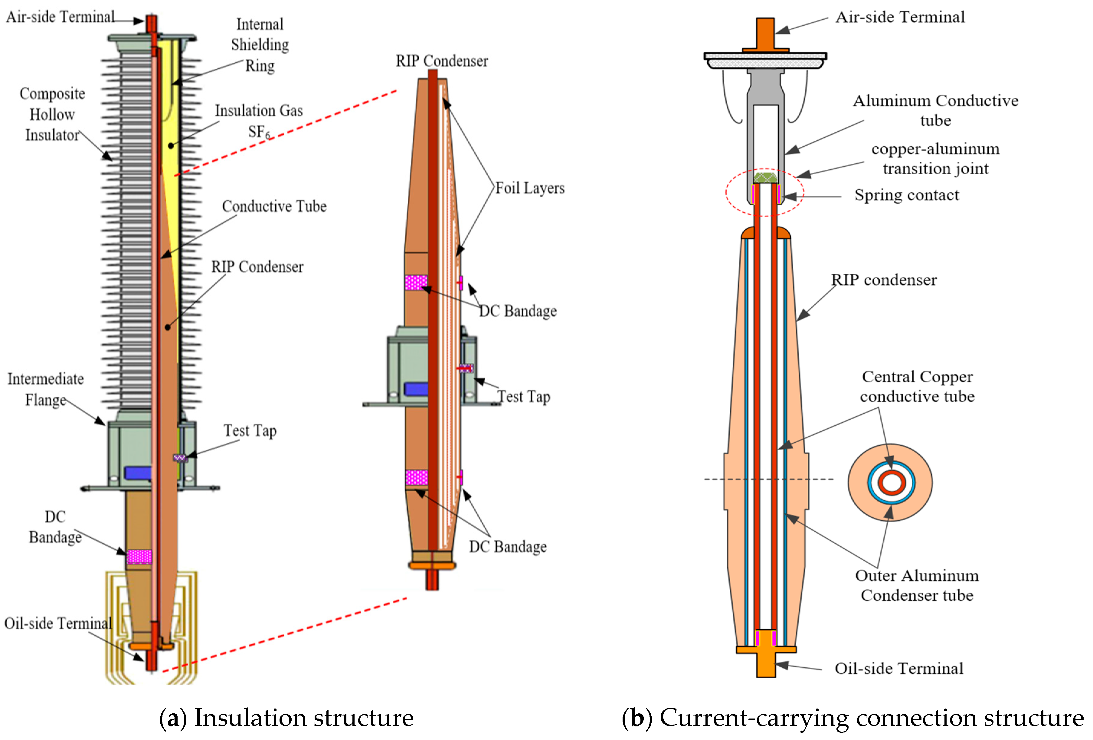
From September 2015 to June 2019, several ± 500 kV RIP valve side bushings from Yimin converter station, Tuanlin converter station and Fengjing converter station were found to have abnormal overheating defects. Meanwhile, one ± 500 kV RIP valve side bushing in Baoji converter station broke down on April 16, 2017. The insulation structure and current-carrying connection structure of these failed valve side bushings is shown in
Figure 1.
All these bushings have the same insulation and current-carrying connection structure. This paper takes the failed bushing of the Baoji converter station as an example to analyze characteristics and the root cause of this breakdown failure.
The external envelope of the failed bushing is a composite hollow insulator, and its inner insulation is resin impregnated paper condenser body. The space inbetween the insulator and condenser is filled with SF6. Foil layers arranged inside the RIP condenser can control both axial and radial electric field inside the bushing, and as well to adjust external electric field outside the envelope insulator. DC-bandages are designed on the upper and lower surface of RIP condenser to release the surface charge. Inside the RIP condenser of the failed bushing is designed by a double-tube structure. The outer tube is an aluminum alloy tube, which is used to winding the condenser body but does not carry any current. The inner central tube is a copper current-carrying conductive tube. Outside the upper part of RIP condenser body, the inner copper conductive tube and another aluminum conductive tube form a copper–aluminum transition joint through spring contact, which can offset relative displacement of the insulator and conductor when temperature changes.
3. Characteristics and Diagnosis of the Failure
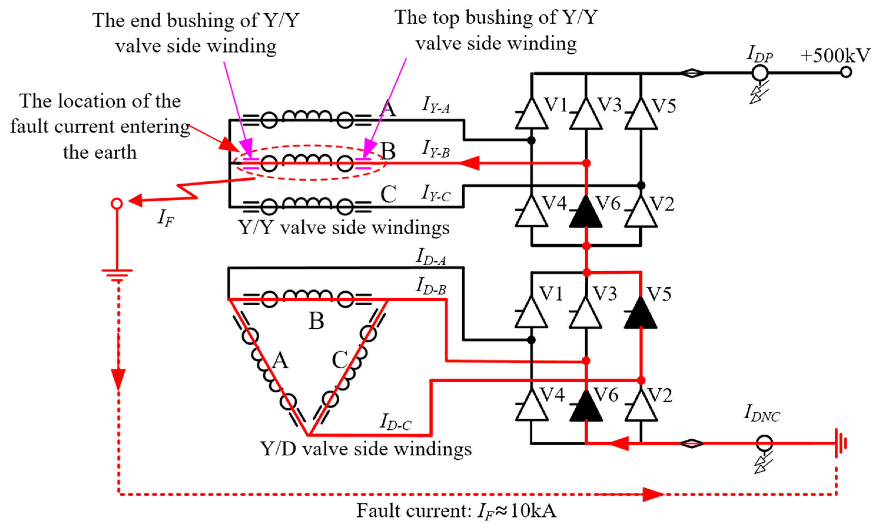
Baoji converter station uses a typical 12-pulse converter system consisting of two six-pulse rectifier bridges in series, three Y/Y converter transformers and three Y/D converter transformers, 12 valve side bushings. Each converter transformer has an end valve side bushing and a top valve side bushing, which are connected to terminals of the valve side winding of transformer. Fault current waveform at the time of the RIP valve side bushing failure, and the insulation characteristic parameters after the failure were measured for the purpose of analyzing the root causes.
3.1. Fault Current Waves and Loop
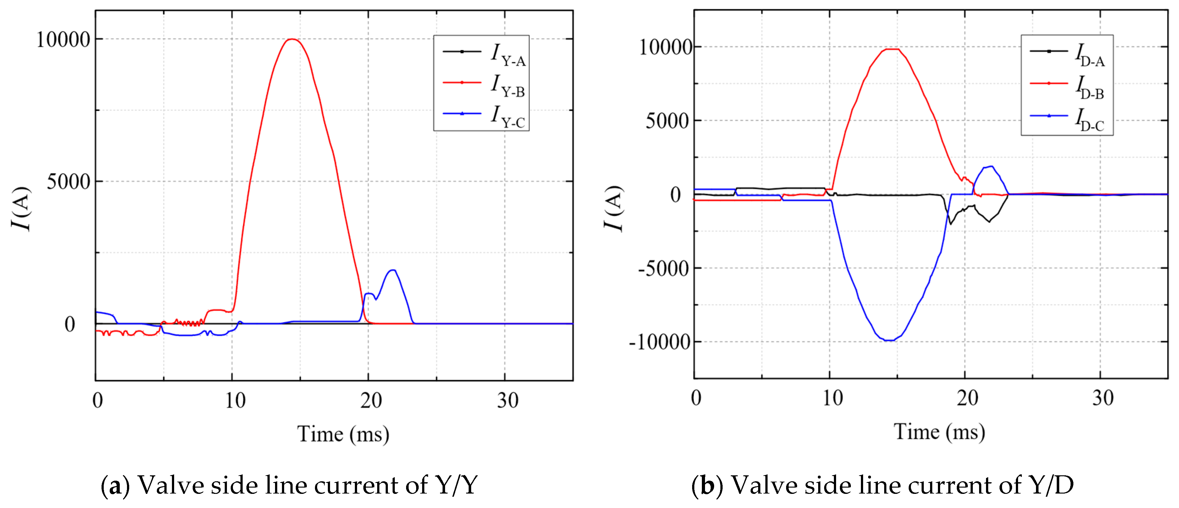
At the time of the RIP valve side bushing failure, valve side line current of Y/Y converter transformer (
IY-A, IY-B, IY-C) and those of Y/D converter transformer (
ID-A, ID-B, ID-C) are shown in
Figure 2a,b. The peak value of fault current which is defined as
IF, and it is equal to
IY-B,
ID-B,
ID-C. These fault current are all 10 kA, shown in
Figure 2a.
IY-A,
IY-C,
ID-A are close to 0 A. Meanwhile, as shown in
Figure 3, the current in the pole line (
IDP) is also 0 A, while the current in the neutral line (
IDNC) is equal to 10 kA. The whole duration time of fault current is about 10 ms, in the meantime, Y rectifier bridge V6 and D rectifier bridge V5 and V6 turn on.
Based on the characteristics of these currents, the flow loop of the fault current in the converter station can be obtained, shown in
Figure 3. The location of the fault current entering the earth can be concluded at the end valve side of Y/Y-B converter transformer. This shows that the end valve side bushing of Y/Y-B converter transformer has been broken down.
3.2. Insulation Characteristics after Failure
Field test results of insulation characteristics on bushings after failure are shown in
Table 1, including the main insulation resistance, test tap insulation resistance, capacitance, dielectric loss factor (tanδ), decomposition gas SO
2 and H
2S on both the top and the end valve side bushings of Y/Y converter transformers in phase A, B and C. Meanwhile, an oil sample was also taken from the converter transformers, and the DGA result including C
2H
2, H
2 and total hydrocarbon is also showed in
Table 1. DL/T 393-2010 standard specifies values of these insulation characteristics.
Field test results of insulation characteristics in
Table 1 shows that the main insulation resistance of the end valve side bushing for Y/Y-B converter transformer is just 140 MΩ, while that of test tap insulation resistance is close to 0. What’s more, test voltage cannot be applied on the bushing, thus capacitance and tanδ cannot be tested, which indicates that internal breakdown occurs on the RIP condenser between the HV conductive tube and the intermediate flange, and the insulation is totally damaged. SO
2 was also detected inside the composite hollow insulator, and it can be concluded that an arcing path is inside the hollow insulator.
3.3. Overheating and Arcing Trace of Disassembled Bushing
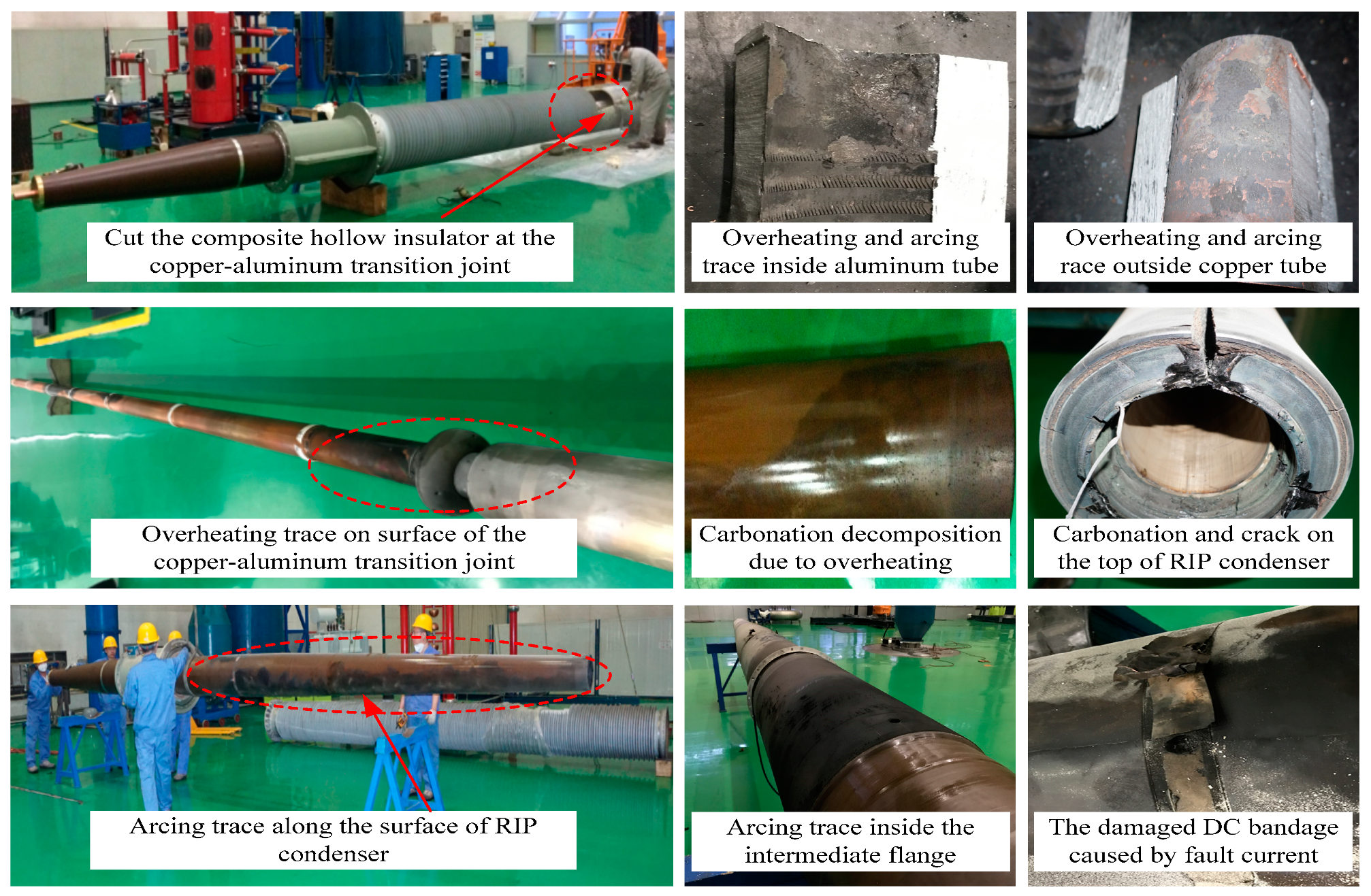
After removing the failed bushing from the converter transformer, dc resistance test and disassemble inspection was carried out. The total conductive tube dc resistance of the failed bushing is above 1900 μΩ, which is much higher than that of the normal value (less than 50 μΩ). Arcing trace and overheating trace on RIP condenser, intermediate flange and conductor, as well as overheating trace on current-carrying conductive tubes and insulating material, are recorded during each step of the disassemble process.
The arcing and overheating traces of the disassemble inspection on the failed bushing is shown in
Figure 4. When the composite hollow insulator is cut down, obvious overheating trace is found on the contact surface of the copper–aluminum conductive tube transition joint. Inside the joint, partial contact surface of both copper conductive tube and aluminum conductive tube has been melt, and the spring contact between two tubes is totally damaged. Due to overheating, cracking and carbonization of the top RIP condenser close to the transition joint has occurred. Some carbonized decomposition particles are attached to the top-part surface of RIP condenser.
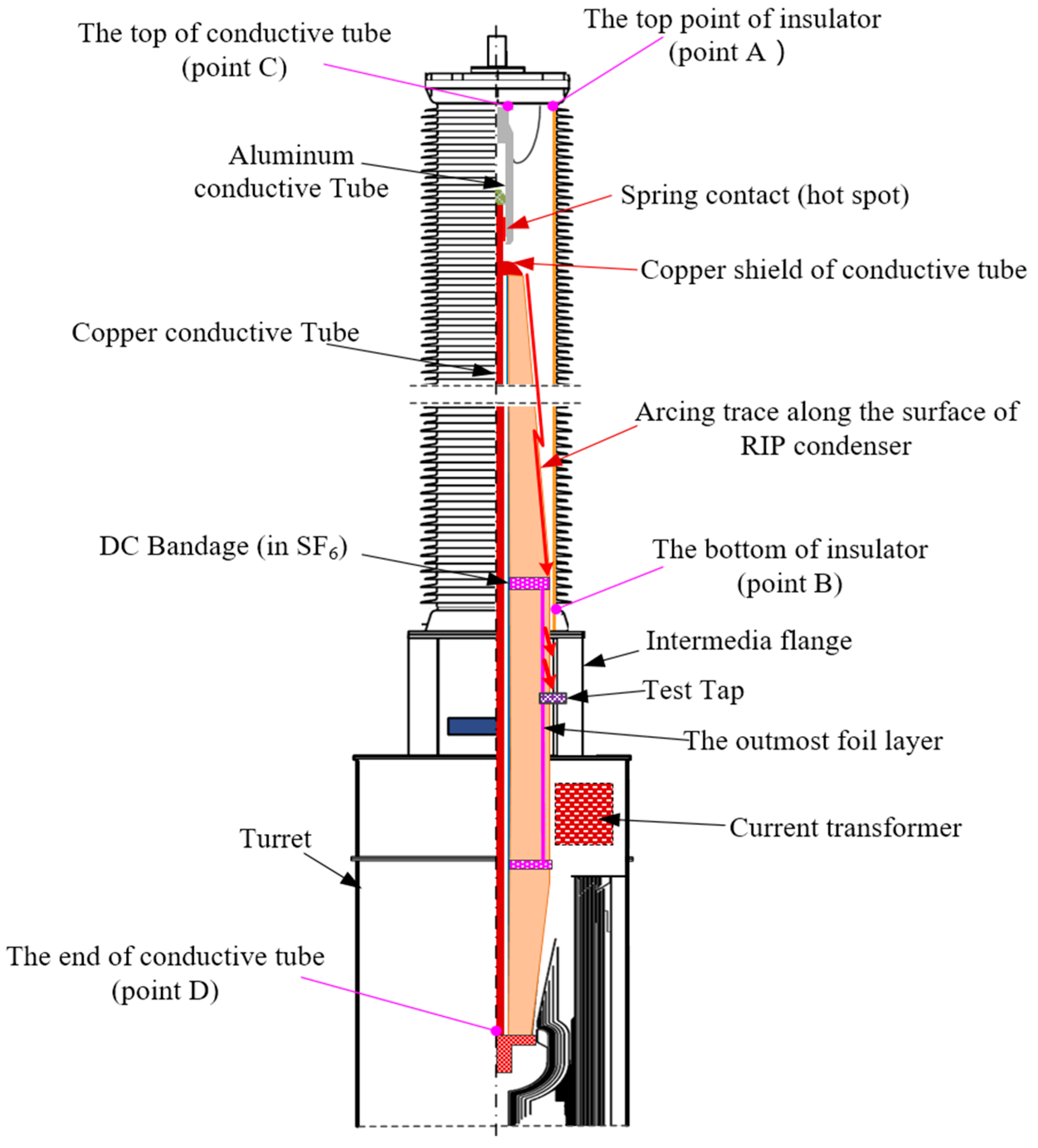
There is a clear axial arcing trace on the surface of RIP condenser, which starts from the top-part surface of RIP condenser close to the high voltage conductive tube to the DC bandage which is grounded to the earth. All these overheating and arcing trace indicate that there is an axial flashover along the RIP condenser/SF
6 interface. Axial flashover arcing path of the failed bushing is showed in
Figure 5. The arcing path starts from the copper shield of conductive tube at the top of the RIP condenser, along the interface of the RIP condenser and SF
6, after passing through the DC bandage and finally enter the earth through the test tap and intermediate flange.
It was clear that the solid insulator material (resin impregnated paper) around area of the copper–aluminum transition joint has been carbonized due to the overheating of high abnormal contact resistance at the copper–aluminum conductive tube transition joint. These carbonation decomposition particles are attached to the surface of RIP condenser which can lead to a reduction in the flashover voltage. Influence of partial overheating of abnormal copper–aluminum transition joint inside bushing on abnormal temperature distribution is analyzed in
Section 4.
3.4. Typical Breakdown Failures Diagnosis
When analyzing the failures of the valve side bushings, the location where the fault current flows into the earth can be concluded by the magnitude and direction of the fault current in the converter station and the characteristics of the fault current flow loop. Through the multiple external features of the valve side bushing where the fault current enters the earth, including external visual inspection of arcing traces, the capacitance and insulation resistance of the bushing condenser, the decomposition gases of SF6, and the dissolved gas of converter transformer oil, the types of breakdown inside or outside valve side bushing can be deduced.
For the failed RIP valve side bushing of Baoji converter station, there is no arcing trace outside the composite hollow insulator and the DGA result of transformer oil is normal. However, the main insulation resistance, the capacitance and the dielectric loss factor of the bushing are all abnormal, and large amount of SO2 gas from SF6 decomposition is also detected inside the composite hollow insulator. Based on all these test results, the type of bushing failure can be diagnosed as axial flashover along the condenser/SF6 interface.
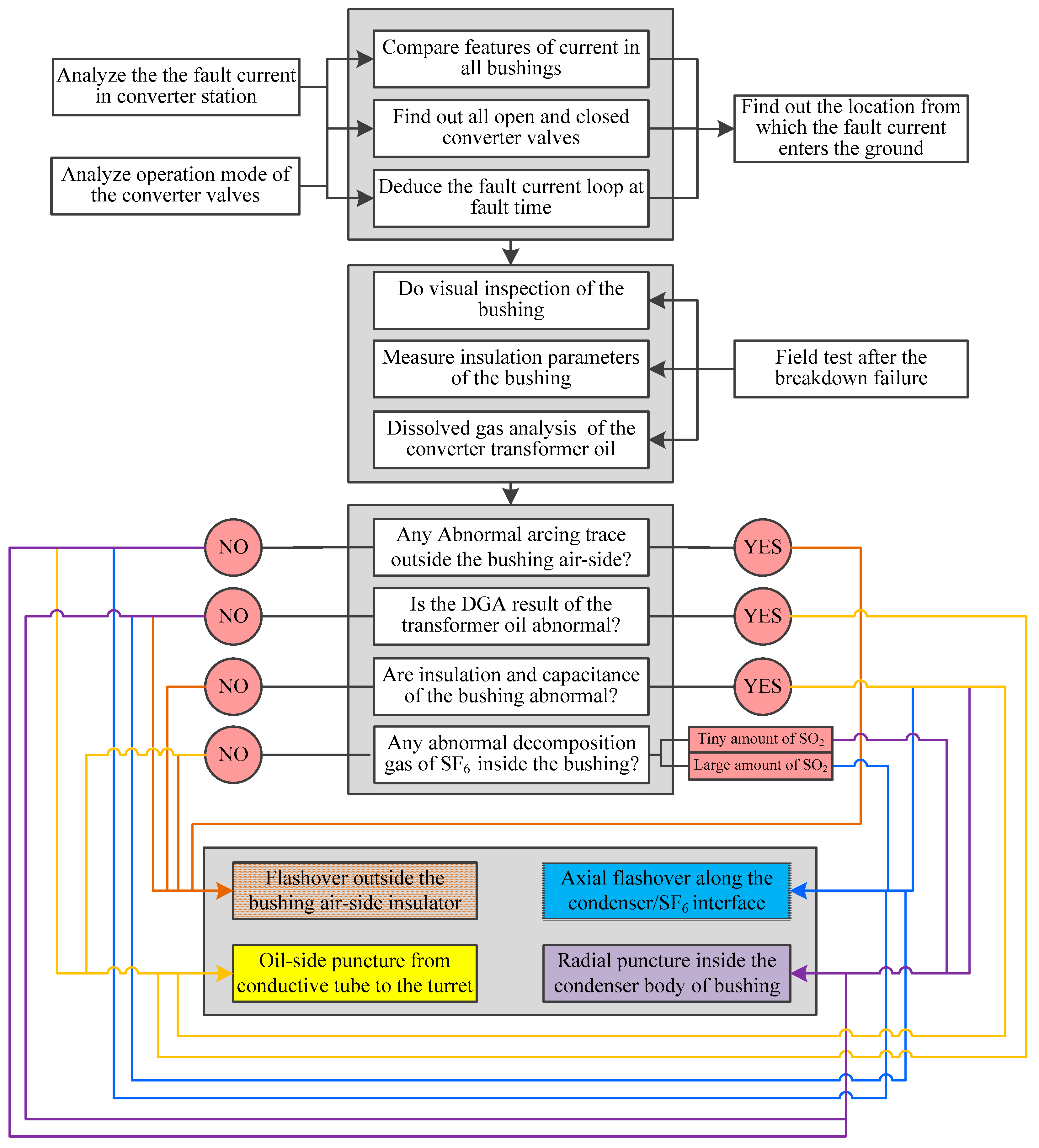
According to four characteristics of failed RIP valve side bushing and its related converter transformer, which include external arcing traces of the bushing air-side, dissolved gas analysis results (DGA) of converter transformer oil, capacitance and insulation characteristics of bushing’s condenser, decomposition gases of SF
6 inside the bushing’s composite hollow insulator, four typical breakdown failures and their diagnosis method are proposed. These breakdown failures are flashover outside the air-side of the composite hollow insulator, axial flashover along the RIP condenser/SF
6 interface, radial puncture inside the RIP condenser, and oil-side puncture from conductive tube to the bushing turret. The diagnosis flow chart is shown in
Figure 6. Some more cases of breakdown bushings indicate that a defect caused by axial flashover along the condenser/SF
6 interface is generally accompanied by large amount of SO
2, and the recommended concentration of this gas is greater than 100 μL/L. While a defect caused by radial puncture inside the condenser body of bushing is usually accompanied by tiny amount of SO
2, and the recommended concentration of this gas is undetectable or less than 5 μL/L.
4. Temperature Simulation and Analysis on the Failed Bushing
In normal condition, the DC resistance R0 of failed bushing in Baoji converter station is 35 μΩ, but for the failed state, it is 1900 μΩ, of which 1855 μΩ is the resistance of the spring contact transition joint between the copper and aluminum conductive tubes. The causes of abnormal contact resistance include the non-concentric installation of the copper–aluminum conductive tube, insufficient contact area between copper–aluminum tubes with spring contact finger, as well as improper treatment of silver plating on contact surface.
In order to analyze the influence internal temperature distribution of the abnormal contact resistance under various load current, the total normal resistance loss and the total abnormal contact resistance loss of the copper–aluminum transition joint at 0.25 p.u., 0.50 p.u., 0.75 p.u. and 1.00 p.u. load current are calculated respectively. Considering the mainly harmonic number
h is 1, 5, 7, 11 and 13, the corresponding resistance loss
PR0_h and
PRc_h are calculated and shown in
Table 2.
P1,
P2,
P3, and
P4 which are consist of Σ(
PR0_h) and Σ(
PRc_h) represent the total resistance loss of all harmonic current resistances at load currents of 0.25 p.u., 0.5 p.u., 0.75 p.u.. Also, 1.0 p.u..
PR0_h is the heat loss of a single harmonic current with a normal DC resistance
R0, while
PRc_h is the heat loss of a single harmonic current with abnormal contact resistance, and
h can be 1, 5, 7, 11, or 13.
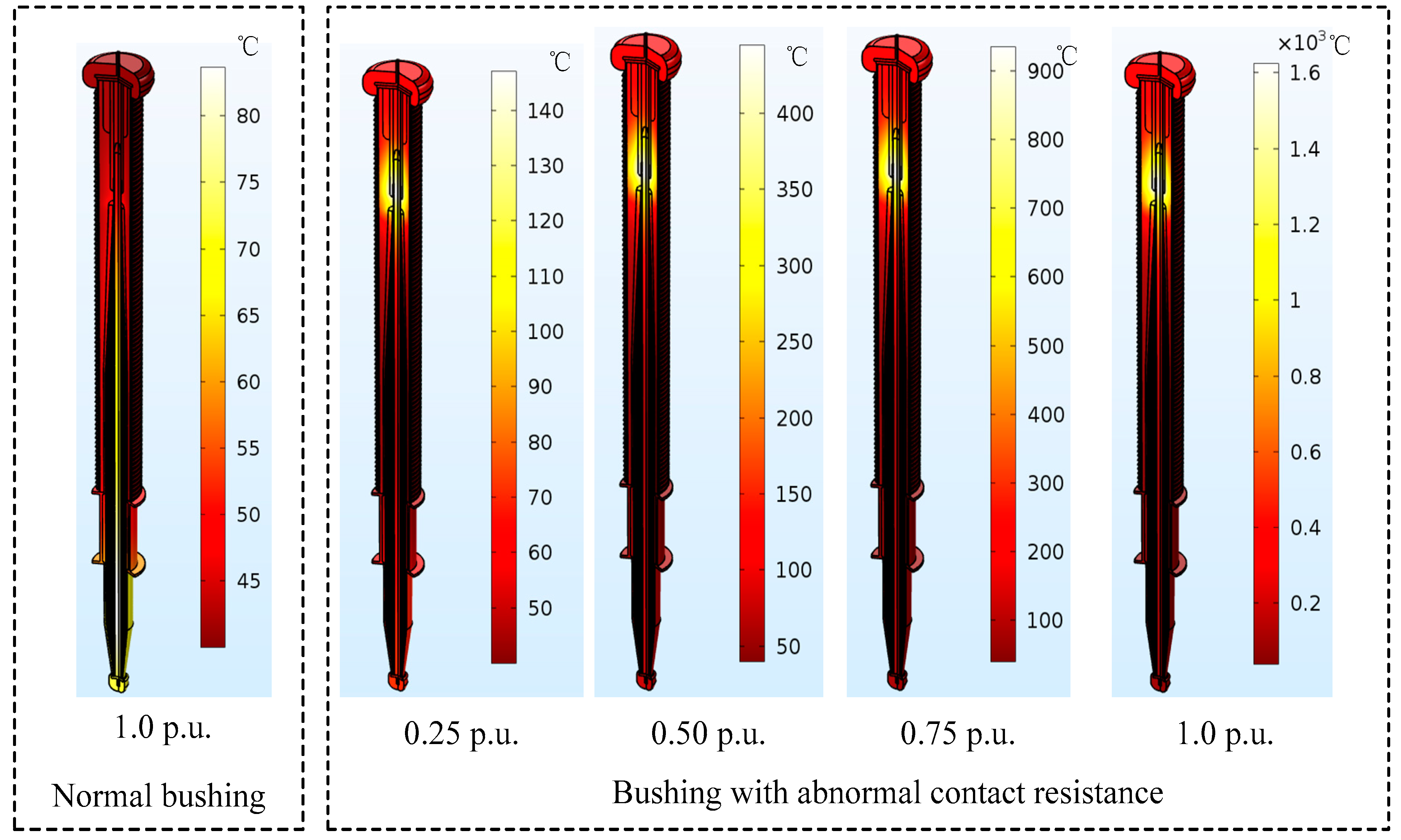
The finite element simulation model with an abnormal contact resistance between the copper conductive tube and aluminum conductive tube is established. According to
Table 2, the total resistance loss Σ(
PR0_h+PRc_h) of the load current of 0.25 p.u., 0.5 p.u., 0.75 p.u., 1.0 p.u. is applied to the bushing model, and the simulation result of the internal temperature distribution of the bushing is shown in
Figure 7. In the simulation model, the temperature in the valve side bushing oil is set to 70 °C, and the ambient temperature of the air side is set to 40 °C.
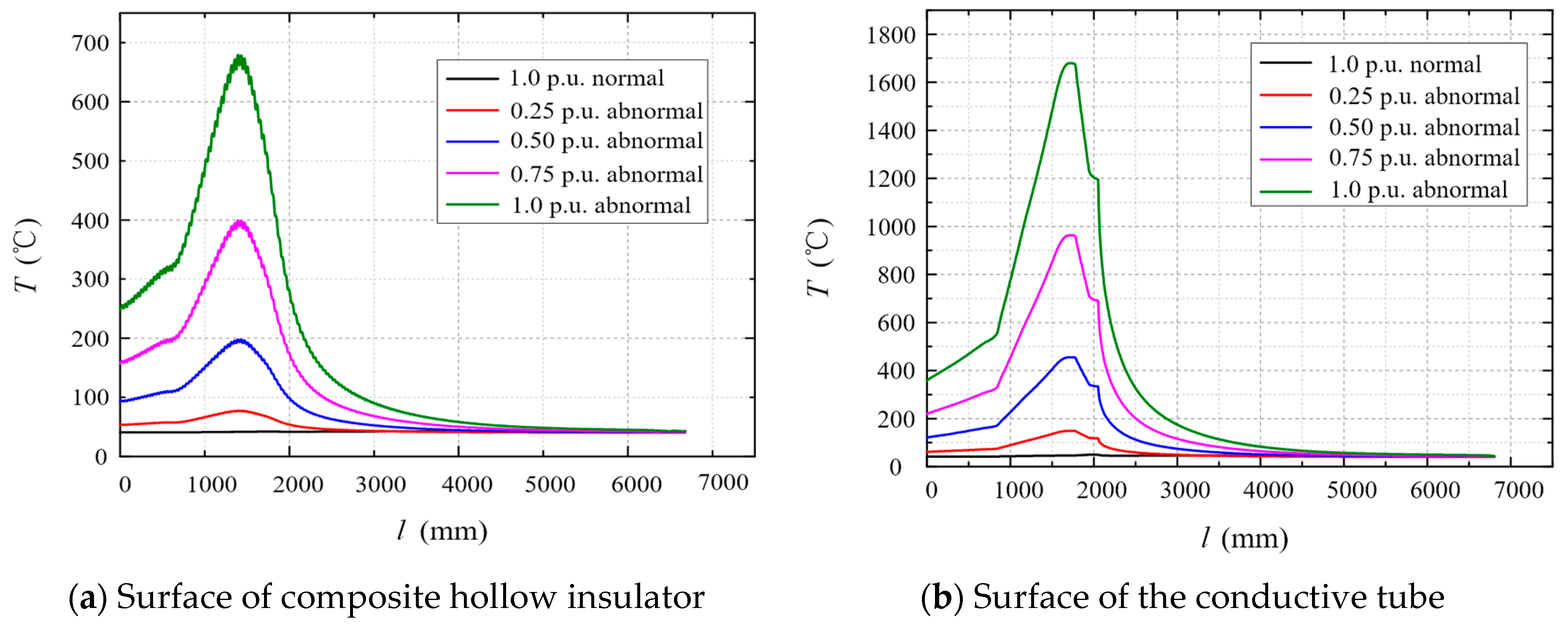
Temperature curves along the surface of the composite hollow insulator from point A to point B outside the bushing, and temperature curves along the surface of the copper–aluminum conductive tube inside the bushing are shown in
Figure 8. The four points A, B, C and D are indicated in
Figure 5. These temperature curves include simulation results under 1.0 p.u. load current with normal conductive resistance, as well as under 0.25 p.u., 0.50 p.u., 0.75 p.u., and 1.0 p.u. load current with abnormal contact resistance between the copper and aluminum conductive tubes.
It can be seen from
Figure 8 that when the copper–aluminum transition joint of the bushing is normal (
Rc = 0), the surface temperature of the insulator is 40 °C under rated load current (1.0 p.u. normal), and the copper–aluminum transition zone temperature is also 40 °C.
When spring contact of the copper–aluminum conductive tube is abnormal (
Rc = 1855 μΩ), the temperature of the silicone rubber insulator reaches 75 °C under the load current of 0.25 p.u., and the temperature of the transition joint between the copper and aluminum conductive tubes (the highest point of the purple curve in
Figure 8b) reaches more than 150 °C, which is higher than the temperature limit 120 °C specified by IEC standard. Therefore, from the analysis results, it can be seen that the maximum safe operation current of the defective bushing with abnormal contact resistance is not above 0.25 p.u.
As the load current increases to 0.75 p.u., the temperature of the transition joint is close to 1000 °C, at which temperature the copper conductor will begin to melt. The temperature at the upper part of the RIP condenser close to the transition joint is also more than 200 °C. Under this extreme condition, partial material of the upper RIP condenser begins to carbonize and decompose. Carbonized decomposition products of solid insulating materials and metal melts can contaminate the interface between the RIP condenser body and the SF6 gas, reducing the dielectric strength of bushing and ultimately causing the axial flashover along the condenser/SF6 interface.
5. Field Repair of Defective Bushings
The analysis in this paper shows that the overheating of the copper–aluminum conductive tube transition joint of the RIP valve side bushing can lead to axial flashover along the RIP condenser/SF
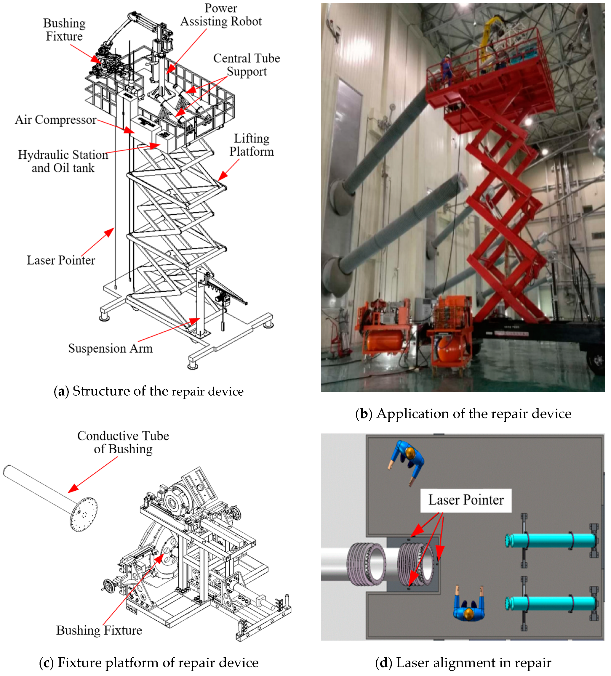
6 interface. To solve the similar problems of the same type bushing in Yimin converter station, Tuanlin converter station and Fengjing converter station, a special bushing repair device is developed, which can be used to repair defective bushings on-site directly without pushing converter transformers away from the valve hall and without pulling out the bushing from the converter transformer. The bushing field repairing device is suitable for all valve side bushings with spring contact joint conductive tube. The structure of the repair device for defective bushings is shown in
Figure 9.
The bushing field repair device shown in
Figure 9 includes lifting platform and power assisting robot, hydraulic station, laser pointer and bushing fixture respectively mounted on the lifting platform. The device can be used to quickly and cost-effectively disassemble and assemble the defective RIP valve side bushing and its composite hollow insulator, as well as accurately control the force and distance required to disassemble and install the conductive tube with the help of the assisting robot and laser pointer.
The procedure of field repairing for abnormal copper–aluminum conductive tube transition joints on defective bushings includes pre-treatment, bushing and repair device positioning, top cover removal, defect inspection and treatment, replacement parts handling, bushing reassembling, post-treatment and testing. Using the field repair device, a total of 75 bushings with overheating hidden defects in copper–aluminum transition joints in the State Grid Corporation’s system of ±500 kV Tuanlin, Fengjing, Baoji, Mujia and Yimin converter stations are repaired on site. All the 75 bushings have the same structure as the bushing shown in
Figure 1. In addition, when they were running under rated load current, it was found through infrared accurate temperature measurement that the hottest spot of the composite hollow insulators was located one third of the distance from the air-side terminal, corresponding to the position of copper–aluminum conductive tube transition joint inside these bushings. Before field repair, in some of the 75 bushings, decomposition gas SO
2 caused by micro-discharge under combined heat and electricity had been detected, which is more than 50 μL/L. After the field repair, the main insulation resistance, the capacitance, the dielectric loss factor, the content of SO
2, the SF
6 leakage rate of the repaired bushing, as well as dc resistance together with converter transformer winding have been tested and fully meet the operational requirement. All these repaired RIP valve side bushings are now in stable operation.
6. Conclusion
In this paper, the characteristics of a RIP valve side bushing breakdown failure caused by an abnormal contact at the copper–aluminum conductive tube transition joint is analyzed, and then according to these analysis, a method of diagnosing four typical internal breakdown failures is proposed. Meanwhile defective bushings of the same type are repaired by using a field repair devices, drawing the following conclusions:
- (1).
In a converter station with structure of 12-pulse valves, when any one of 12 valve side bushings breaks down, the position of the fault current entering the earth and the location of related failed bushing can be accurately diagnosed by the characteristics of all valve side currents in Y/Y and Y/D converter transformers, the magnitude of current in the Pole line and neutral line, as well as the opening and closing status of each converter valve.
- (2).
Based on the analysis of capacitance, insulation resistance, SF6 decomposition gas, external air-side arcing trace on a failed RIP valve side bushing, as well as the DGA result of the related converter transformer oil, the type of the breakdown failure can be diagnosed, including flashover outside the air-side of the composite hollow insulator, axial flashover along the RIP condenser/SF6 interface, radial puncture inside the RIP condenser, and oil-side puncture from conductive tube to the bushing turret.
- (3).
For the valve side bushing with abnormal contact resistance at the copper–aluminum transition joint, by applying the total resistance loss of all harmonic current resistances at the area of the copper–aluminum conductive joint, the finite element temperature simulation can be used to obtain the temperature values inside and outside the bushing under different load current. Thus the safety operation current of the defective bushing can be determined.
- (4).
When repairing and replacing components of the this abnormal contact resistance bushings on-site, it is necessary to accurately control the installation force, the installation angle, and installation distance. The special field repair device with laser pointer and power assisting robot can complete this complex and difficult task.
The transition joint of two conductive tubes is the weak point of RIP valve side bushing. When the contact resistance increases, long-term overheating can be developed into a serious breakdown failure. There are many researches on the influence of metal particles on the flashover properties of solid insulation, but rarely studying on insulating carbonized decomposition particles. Thus when the RIP condenser/SF6 interface is attached with the insulation carbonized decomposition particles, axial flashover mechanism needs further study.


