Article

Data Centers as Active Multi-Energy Systems for Power Grid Decarbonization: A Technical and Economic Analysis

by
Pio Alessandro Lombardi
1,*,
Kranthi Ranadheer Moreddy
2,
André Naumann
1,
Przemyslaw Komarnicki
1,
Carmine Rodio
3 and
Sergio Bruno
3
1
Convergent Infrastructures, Fraunhofer Institute for Factory Operation and Automation IFF, 39106 Magdeburg, Germany
2
Ventury GmbH, 01309 Dresden, Germany
3
Department of Electrical Engineering and Information Technology, Politecnico di Bari, 70126 Bari, Italy
*
Author to whom correspondence should be addressed.
Energies 2019, 12(21), 4182; https://doi.org/10.3390/en12214182
Submission received: 7 August 2019 / Revised: 21 October 2019 / Accepted: 28 October 2019 / Published: 1 November 2019
(This article belongs to the Special Issue Optimization of Multicarrier Energy Systems)

Abstract

:
Power system decarbonization will be one of the main challenges confronting society over the next twenty to thirty years. Renewable energy sources (RES), such as wind and solar, will be the main resources supplying the power grid. Given their volatility, their integration into the grid necessitates planning and utilizing new flexibility options. Energy storage systems (ESS), multi-energy systems and active consumer involvement are three solutions attracting the scientific community’s attention. Data centers (DCs) provide a very high degree of flexibility for consumers. They can be utilized to support system operators or integrate power generated by locally installed renewable energy source generators in the DC’s network. This study is intended to contribute by developing a methodology for planning new flexibility options in DCs. The methodology developed treats DCs as active multi-energy systems. Control strategies were also developed. The technical and economic performance of the solutions implemented was evaluated.

1. Introduction

Volatile renewable energy sources (RES), such as wind and solar, will be the main energy sources supplying future power systems. The European Union intends to cover 80% of the total load with RES by 2050 [1]. However, the integration of such volatile energy sources in the grid is a huge challenge for system operators. More flexibility options need to be planned in order to integrate volatile RES fully [2]. Such flexibility options could be supplied by energy storage systems (ESS), multi-energy systems (MES) and active consumer involvement in power system management [3,4,5]. In MES, energy converted into any form can be used to provide the flexibility resources necessary to regulate and balance power systems, exploiting for example the intrinsic storage resources of thermal systems (as in the case of the thermal inertia of buildings). Data centers (DCs), which are impacting our society and economy due to the digital transformation, are becoming one of the main important and critical infrastructures of modern society [6,7,8,9], and can provide a significant contribution to flexibility. DCs are characterized by highly intensive energy consumption, due mostly to the necessity of avoid overheating of equipment through cooling systems. Moreover, due to the strict requirements in terms of reliability and power quality, DCs are often equipped with energy storage. The ESS, primarily thermal ones since electrical storage is mostly deputed to guarantee immunity from voltage perturbations and interruptions, could be integrated in a DC to optimize energy conversion (from electricity to cold) and (cold) energy supply processes. The use of thermal ESS (TESS) together with new control strategies would make it possible to increase the flexibility degree that DCs could provide system operators. The planning and operation of new flexibility options would allow DC operators to adopt demand response (DR) programs or to operate DC according to signals from the electricity market operator.
The possibility of operating DCs as active MES has captured the attention of many researchers in the last few years. The concept to plan DCs according to the “net-zero-energy” approach has been formulated in [10,11]. In both cases, the DC’s thermal loads have been considered as a flexibility option to match the DC´s load, according to the electric power generated by volatile RES. In [12], the integration into the DC´s building of cool air from the outside environment has been analyzed as an option for decreasing the electric load and increasing the flexibility of the DC´s loads. Control strategies for DR based on the bargaining procedure has been investigated in [13]. The DR strategies developed allow the power generated by volatile RES and the price signals sent by the electricity market operator to be combined optimally. The design of a DC as a direct continuous network has been investigated in [14,15]. It has been estimated that energy savings can reach upward of 30% and the power generated by volatile RES can be integrated more easily into the DC network. The utilization of thermal (cold) storage systems for increasing the flexibility of the loads have been investigated in [16,17]. Control strategies were developed to minimize the operational costs of the DCs. In addition to using ESS, strategies for controlling the sleep mode of the servers have been proposed as a solution for increasing the energy efficiency of DCs [18].
This paper presents a methodology for planning and operating new flexibility options for active DC operators and an evaluation of their economic and technical performance. The DC analyzed is an active MES in which a reversible heat pump converts electricity into thermal energy (cooling). Different types of TESS (latent and sensible) allow an increase of the DC’s degree of flexibility and operating the DC more efficiently. The main contribution of the methodology developed lies in having a holistic view regarding identifying and operating the flexibility options. Differently from other approaches found in the literature, the proposed control methodology allows to take advantage concurrently of both flexibility resources offered by the thermal inertia of the DC’s building and by the thermal (cold) storage systems.
The advantage to using such a planning methodology lies both by the system operators as well as by the DC operators. Indeed, the system operators might save investment on new flexibility options (i.e., batteries), which need to be integrated into the electric network. On the other side, the DC operators might sell their flexibility to the system operators and therefore improve their business model or using dynamic electricity price and therefore decreasing the energy costs. A DC with the weather conditions of the city of Dresden (Germany) was the case study analyzed. The study does not consider the system operator point of view, but it analyzes the advantages to exploit flexibility from the DC’s operator perspective only. The control strategy suggested for exploiting the flexibility makes energy savings of about 8% possible.
The role of DC in the power systems of the future is described in the first section of this paper. A thermoelectric model of a DC as an MES is presented in the main section. The case study and its results are discussed in the final section of this paper.

2. The Data Center’s Role in the Future Power System

Digital transformation has changed the way in which people interact with each other. The DCs are becoming a critical infrastructure for the whole society. They process an enormous quantity of data consuming huge amounts of electric power. They now require almost 1–1.5% of the global electricity demand [19]. This share will increase to 13% by 2030 [20,21]. The DC will be one of the main consumers of electricity by 2030, together with electric vehicles, which are expected to have a demand ranging between 640 TWh and 1110 TWh [22].
Cooling systems alone consume almost 35–45% of the total electricity supplied to DCs. The remaining electricity is divided among information technology (IT) equipment (40–50%), lighting (2–5%) and power losses (10–17%) (see Figure 1). This breakdown of electricity consumption makes DCs very attractive to system operators that need active and flexible loads to integrate power generated by volatile RES in the grid better [23,24]. The nature of RES, such as wind and solar, make it necessary for system operators to take so-called “redispatch actions” to compensate for volatile power generation by RES and their generation prediction error. The TESS and the thermal inertia of the building in which data servers are located can be used to supply the DC’s cooling load with a very high degree of flexibility. In addition to standard TESS, the performance and technical and economic attractiveness of other TESS, such as ice and seasonal cold storage systems are capturing the scientific community’s attention [25,26,27,28]. The combination of TESS and electric reversible heat pumps allows DC operators to employ DR programs [29,30] or to participate in flexibility platforms, such as the one developed in the WINDNODE project in Germany [31]. Energy costs can be reduced and new business models (e.g., flexibility services provider) can be taken advantage of to benefit active consumers.

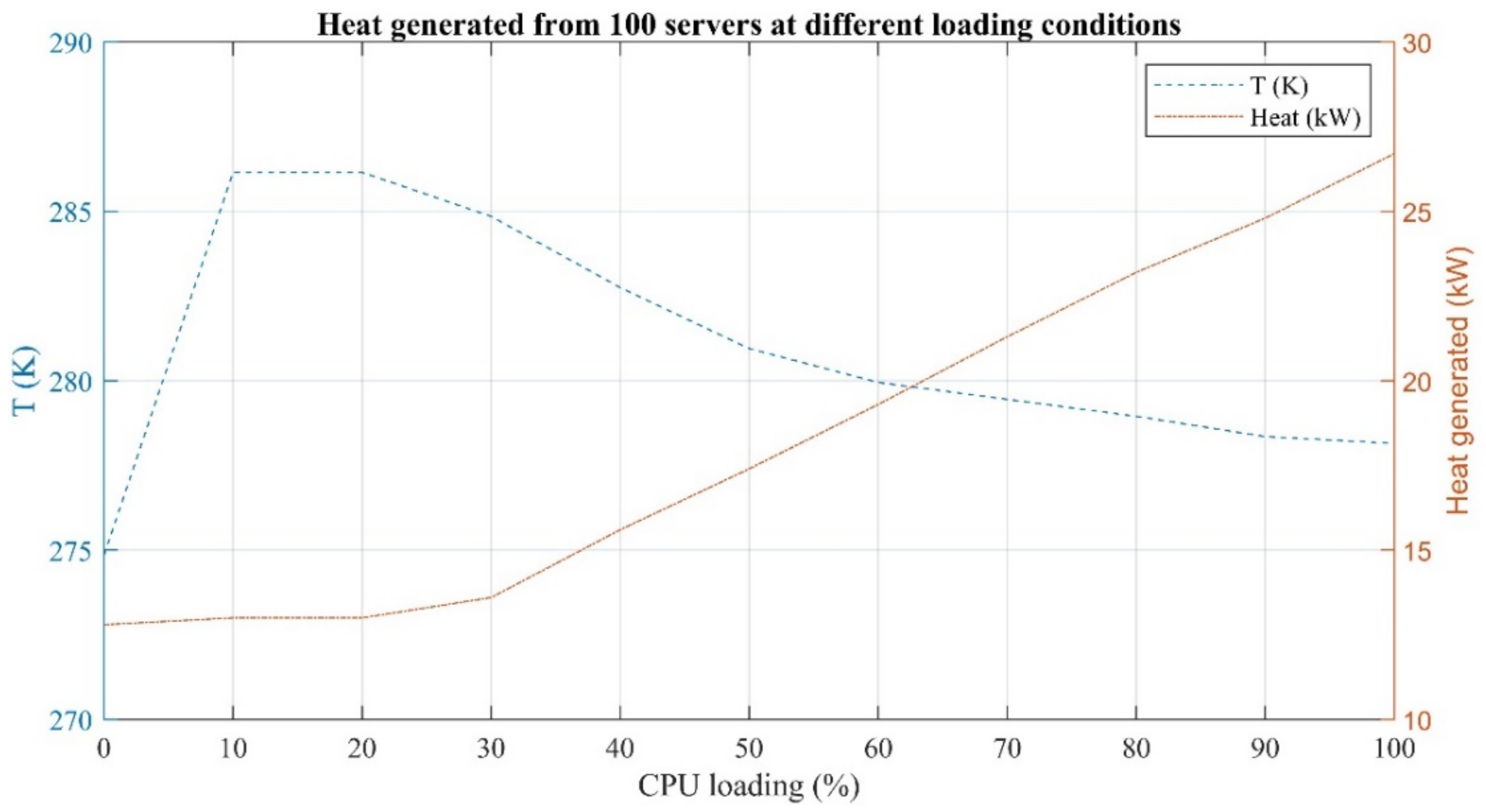
3. Data Centers as Active Multi-Energy Systems: Modeling Aspects and Control Strategies

A share of the electricity demanded in a DC system is converted into thermal energy to cool the temperature of data server rooms. The thermal energy can be used directly to cover thermal loads or stored in different TESS. Either latent or sensible TESS can be selected, depending on the storage temperature. The DC considered in this study was an active MES. A methodology for modeling the flexibility option within a DC was developed to evaluate its technical and economic performance. In the first three steps, the features of the DC building (e.g., area, number of floors, height of floors and number of windows) and the weather conditions at the location of the DC building are parametrized using the software SimulationX (ESI IT GmbH, Dresden, Germany) [32]. In the fourth step, the data server room temperature control algorithms are developed. Flexibility options (e.g., TESS capacity, utilization of the building’s thermal inertia) are planned in the fifth step. The consideration of the flexibility during the planning phase could be a wise choice since it might be used both for enlarging the business model of DC or for decreasing their energy costs. Figure 2 presents an overview of the methodology developed.
The models created in step three are based on a synthetic electric power profile of the IT equipment’s power consumption, which are incorporated within the SimulationX database. The profile was successively normalized to estimate the server’s central processing unit loading. The heat generated by servers (Qserver) that must be removed from the data server room is calculated based on the data collected in [33] and presented in Figure 3. T specifies the difference between the inlet and output temperature of the cooling medium in different processing data conditions.
In addition to Qserver, the heat caused by solar gain, Qsol, (see Equation (1)), and the heat transferred from the building’s walls to the outside environment, Qtrans, (see Equation (2)), should also be examined. The total heat to be removed is calculated by Equation (3). The negative sign before Qtrans represents the case when the environment contributes to cooling data servers (usually during the winter). Electric energy consumption depends on the coefficient of performance of the reversible heat pumps utilized to remove heat. Ambient temperature also affects the coefficient of performance of reversible air-to-water heat pumps, while water source temperature affects the coefficient of performance of reversible water-to-water heat pumps. Table 1 presents all of the parameters analyzed.
Q s o l   =   g   ×   A i   ×   I i
Q t r a n s   =   A i   ×   U i   ×   T r o o m T a m b i e n t    
Q r e m o v e   =   Q s e r v e r + Q s o l ± Q t r a n s
One of the main indicators utilized to evaluate the energetic performance of DCs is the power usage effectiveness (PUE), which is estimated as a ratio between the total consumed electric power and the electric power consumed by the IT system, as Equation (4).
P U E   =   T o t a l   F a c i l i t y   P o w e r I T   E q u i p m e n t   P o w e r
The higher the PUE value, the lower the energetic efficiency of the DC, since a large part of the electricity consumed is not used for the IT load. A PUE value of 1 depicts the ideal case in which all the electricity consumed is used to serve the IT equipment. According the analysis carried out by [34], the PUE value ranges between 1.25 and 3.75, with an average value of 1.89 (in 2011). When the DCs are located in high temperature and high humidity zones, they are expected to have a higher PUE value compared to those located in cold temperature and dry zones.

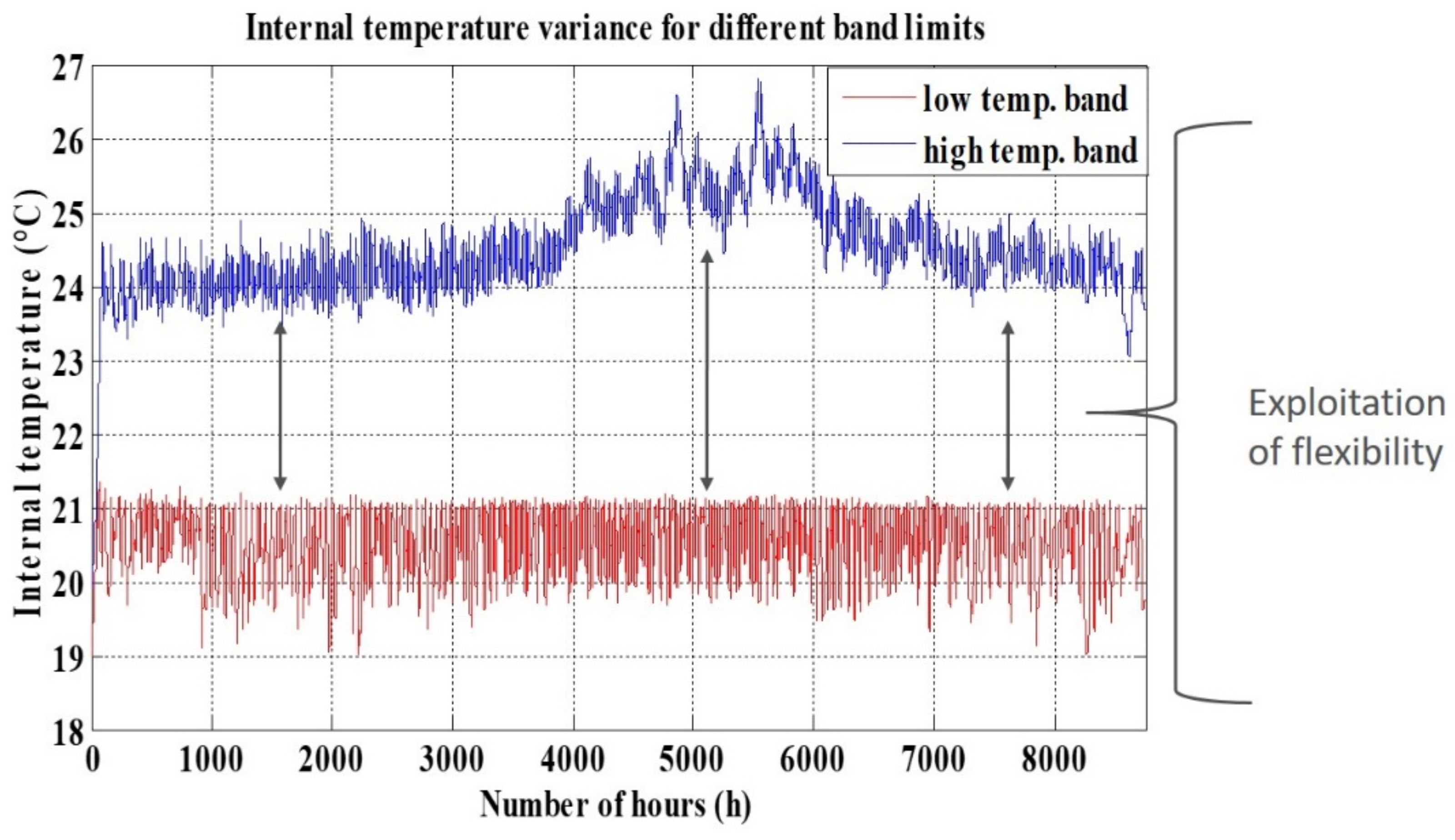
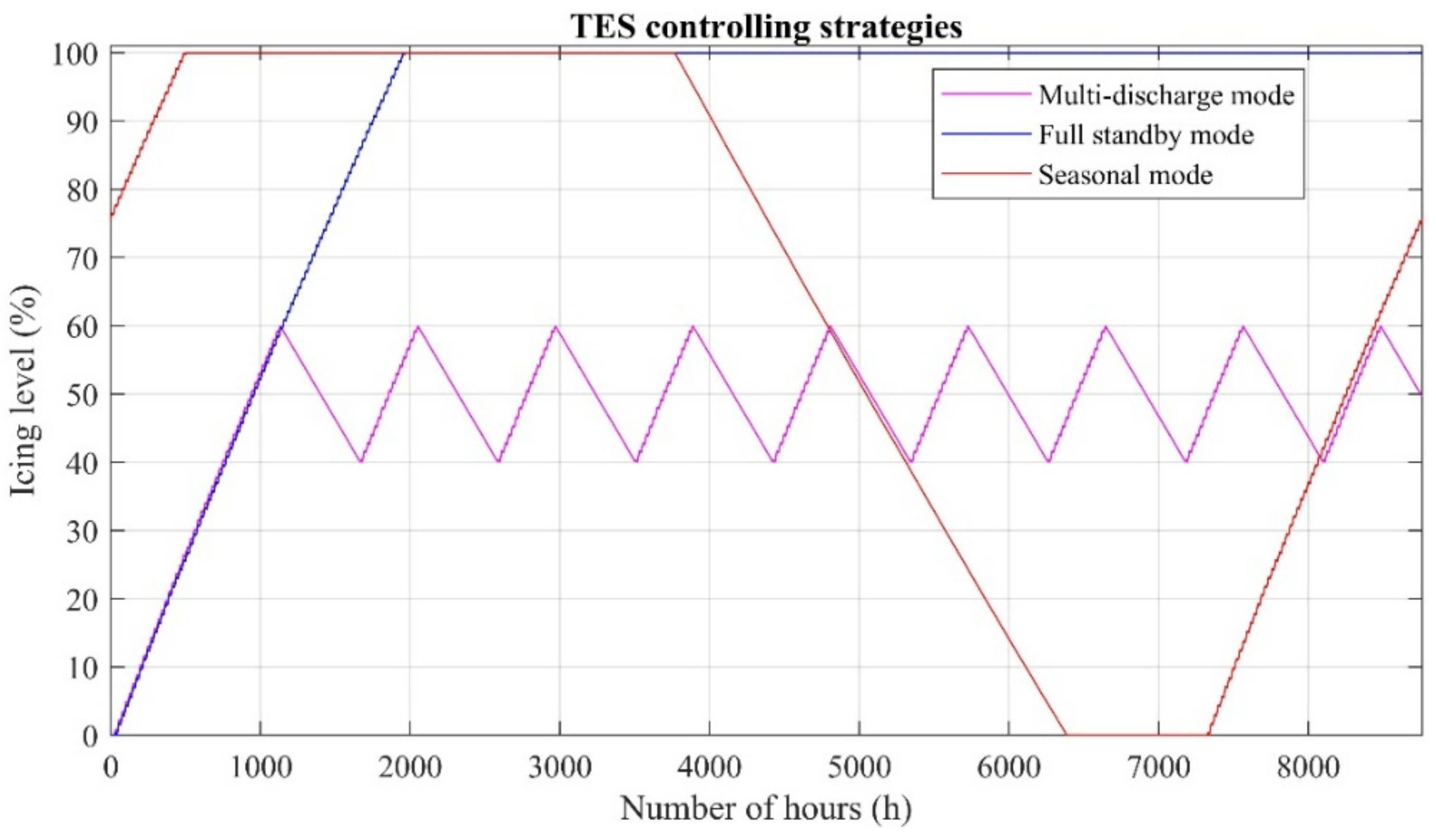
4. Utilizing Flexibility Options in a Data Center: A Case Study

A DC located in Dresden, Germany, served as the case study analyzed to assess the flexibility that a DC operator can provide or utilize. A nonresidential building with a cooling area of 20,363 m2 was analyzed (see Table 2 for the DC building’s main features). Ambient temperature and the direct solar radiation are visualized in Figure 4. The model examines a reversible heat pump that converts electricity into cold. Two different types of TESS were analyzed, namely, latent and sensible TESS. The cold generated by the reversible heat pump is stored in the latent TESS as ice at a temperature ranging between −5 °C and −10 °C. The feasibility of an ice storage system might be justified from the required space. Indeed, an ice storage needs 4–5 times lesser space than chilled water storage. Additionally, the use of the two energy storages is justified by increasing the storage capacity and, therefore, increasing the flexibility to control the DC’s load. One multilayer (10 layers) sensible TESS is used as a (short-term) backup storage system and supplies cold to the DC rooms at a temperature of 4.5 °C. This storage system is necessary since the needed cooling energy is transmitted using a fluid medium. The return temperature of the medium after extracting the heat from the facility ranges between 8 °C and 23 °C. Figure 5 shows the difference between the supply and return temperature of the sensible TESS’s cooling medium. The heat generated by the reversible heat pump and that removed from the DC rooms are stored in another sensible TESS. However, it should be noted that it is an approach adopted by the Software SimulationX. If needed, the latter TESS can serve as the environment into which heat is released. The reversible heat pump is controlled by the temperature of the ice storage system and external signals (i.e., from the market operator or the flexibility market platform). Another control system (DC room temperature controller) is needed to utilize the building’s thermal inertia. Figure 6 is a schematic of the model implemented.
This configuration would enable DC operators to control the system actively. Unlike the IT load that must always be supplied, the thermal load can be used to provide flexibility. Doing this necessitates monitoring at least three parameters: the data server room temperature (Troom), the ice storage system’s state of charge (SOCice) and the electricity price signal. Typically, when DCs are operated passively, Troom does not change from a given temperature generally set between 18 °C and 22 °C. However, according to ASHRAE, DC can be operated up to a Troom of 27 °C, ensuring maximum security and reliability of the IT equipment [35]. This means that the maximum Troom can raise during the day as long as it is controlled to stay below this maximum threshold, thus giving the possibility to increase the flexibility utilizable by the DC (see Figure 7) and exploit the thermal inertial capacity of the DC’s building.
This operational strategy has an effect on total power consumption. In the case of a lower band temperature, load ranges from a minimum of 750 kW to a maximal 1450 kW. The maximal electric power consumed decreases noticeably when a higher band temperature control is used (see Figure 8). By considering one year as time horizon, the high temperature control requires about 1.2% lesser power in comparison with the low temperature control. This difference increases to 4.3% if the only the seasonal effects of summer is taken in consideration. This is a significant result since the summer period can be characterized by relevant demand response events, where a significant amount of regulating power can be needed during morning load de-ramps and evening ramps due to the solar production.
Along with the Troom, the TESS capacity affects the flexibility degree utilizable by the DC. The thermal storage system’s storage capacity is contingent on tank geometry (affecting the medium’s storage volume) and storage temperature. However, control of the Troom and SOCice does not ensure efficient operation of the DC. The charging and discharging strategy for the TESS can also affect the DC system’s total efficiency [36,37]. In order to show how TESS can provide flexibility, three different control strategies, pictorially described in Figure 9, were proposed for the latent TESS in this study:
  • full standby mode;
  • seasonal mode; and
  • multi-discharge mode.
In full standby mode, the ice storage system is controlled at SOCice near 100%. In this case the TESS cannot provide flexibility, just stored cooling power to be used in case of system malfunctions. The system’s flexibility is very limited and cannot be used to repay the requisite capital expenditures and operating costs.
The seasonal mode takes advantage of free cooling during the cold season to charge the ice storage system. It starts to charge from the mid-end of autumn and stores ice for about four months. The discharge starts at the end of the spring season. This strategy has drawbacks because of the high humidity near the DC. Moreover, flexibility can be used only for upward load regulation in winter and downward load regulation in summer.
In the multi-discharge mode, the SOCice is kept within a range of 40–60%. This strategy has a very high degree of flexibility and allows the charging and discharging of the ice storage system according to price signals. Downward and upward regulation services can be provided in all months. Plus, there is always a cold reserve to be used in the case of malfunctions and to ensure system reliability.
The economic performance of the control strategies developed was analyzed by evaluating capital expenditures, Equation (5); operating costs, Equation (6); and total annual costs, Equation (7). The operating costs were estimated for the two different cases. A fixed electricity price scenario was analyzed in the first case and a dynamic tariff in the second (see Figure 10). Table 3 presents the main economic parameters analyzed in the economic analysis.
C i n v . = i C i l i f e s p a n   |   i H P i ,   I S , C P , S U , m
C o p e r . =   h = 1 8760 α   × E h   + β   × P m a x
C t o t a l = C i n v . + C o p e r .
The comparison of the three control strategies revealed that total annual costs are slightly (around 2%) lower when the multi-discharge mode strategy is used rather than the other control strategies (see Figure 11). This difference increases in the case in which the DC operator pays the electricity at a fix price instead of a dynamic price. In this case, the annual cost differences are about 8%. This result is expected because the capital expenditures of TESS cannot be recouped by exploiting price volatility. In the case in which the DC operator uses a fix electricity price, no flexibility is exploited, since storage cycles will only entail losses and, therefore, higher energy costs. The multi-discharge mode strategy, instead, allows the shifting of about 34% of the daily electricity consumption from peak hours to off-peak. Thanks to the continuous control of aisles temperature, the improved flexibility has no impact on the equipment, since temperature never exceeds 27 °C.
The controlling strategies effect the PUE of the DC. Indeed, the results confirm that the full standby mode is the lesser efficient way to operate the DC, since no flexibility option is offered. On the other hand, the multi-discharge mode allows the energetic efficiency to be increased by about 7% (see Table 4), thanks to the full.

5. Discussion

The paper demonstrated how DCs can be controlled as active loads and offer flexibility to the system operator. Thermal energy storage resources, usually installed for reliability purposes, can be exploited concurrently to the thermal inertia of the DC’s building in order to contribute to an increase in DC degree of flexibility. However, thermal storage system controlling strategies need to be implemented to fully exploit the flexibility´s potential. A multi-discharge mode for controlling ice storage system is a better performer when compared with the full standby and seasonal TESS controlling mode. Indeed, both from the economic and efficiency points of view, the multi-discharge mode requires less operating costs and allows the DC to be operated in a more efficient way.
Moreover, the analyzed study case does not consider the intrinsic advantages that the system operators might receive if DC are operated actively. Indeed, the combination of heat pump and thermal storage systems allows exploiting flexibility by offering ancillary services. Having active DCs in their network might allow system operators to save money on investing in new flexibility capacity (i.e., energy storage systems) and operate the network in a more efficient way. By considering these aspects, system operators might economically encourage DC operators (for example, by using attractive power or/and electricity prices) in order that DC operator enlarge their flexibility option and operate the facility in an active way.

6. Conclusions

Power system decarbonization necessitates planning new flexibility options, which could be utilized by system operators to compensate for volatile generation by RES. Operating DCs as flexible loads would yield a solution attractive to both system operators and DC operators, who sell their flexibility or control the DC according to the electricity market or ancillary services signals sent by the market operator of system operators. Operating DCs with a room temperature range between 20 and 27 °C and installing TESS would help to increase the degree of flexibility of DCs. Both combinations were analyzed in this study simultaneously. A case study employing the weather conditions in the city of Dresden was analyzed. The case study has considered the possibility of using two different TESS: latent and sensible storage. The use of a latent TESS that stores the cold as ice allows the storage capacity and therefore the flexibility to be increased. Indeed, this configuration allows degree of flexibility of the DC to be increased. Roughly 34% of the daily energy consumption could be shifted, within a time horizon of 24 h, according to a dynamic price signal. Such a flexible strategy could also be used if the DC is locally supplied by generators based on volatile RES, such as wind or solar. Such flexibility makes it possible to improve the electric efficiency by around 7% when it is compared to a DC which is operated in a passive way. In addition, the strategy developed would cut the annual costs by around 8%. It is expected that the solutions developed might be adopted in 10–20 years as the electric grid will be massively based on generators using volatile RES.

Author Contributions

Conceptualization, P.A.L.; formal analysis, A.N.; investigation, P.K.; methodology, P.A.L., K.R.M., P.K. and C.R.; resources, S.B.; software, K.R.M.; supervision, A.N.; Validation, S.B.; Visualization, C.R.; writing—original draft, P.A.L.

Funding

This research received no external funding.

Conflicts of Interest

The authors declare no conflicts of interest.

References

  1. European Commission. Energy Roadmap 2050. 2012. Available online: https://ec.europa.eu/energy/sites/ener/files/documents/2012_energy_roadmap_2050_en_0.pdf (accessed on 10 September 2019).
  2. Komarnicki, P.; Lombardi, P.; Styczynski, Z. Electric Energy Storage Systems: Flexibility Options for Smart Grid; Springer: Berlin/Heidelberg, Germany, 2017. [Google Scholar]
  3. Alemany, J.M.; Arendarski, B.; Lombardi, P.; Komarnicki, P. Accentuating the renewable energy exploitation: Evaluation of flexibility options. Int. J. Electr. Power 2018, 102, 131–151. [Google Scholar] [CrossRef]
  4. Cesena, E.A.M.; Capuder, T.; Mancarella, P. Flexible distributed multienergy generation system expansion planning under uncertainty. IEEE Trans. Smart Grid 2015, 7, 348–357. [Google Scholar] [CrossRef]
  5. Tran, N.H.; Ren, S.; Han, H.; Jang, S.M.; Moon, S.; Hong, C.S. Demand Response of Data Centers: A Real-time Pricing Game between Utilities in Smart Grid; The Advanced Computing Systems Association: Berkeley, CA, USA, 2014. [Google Scholar]
  6. Dastbaz, M.; Pattinson, C.; Akhgar, B. Green Information Technology. A Sustainable Approach, 1st ed.; Morgan Kaufmann: Burlington, MA, USA, 2015. [Google Scholar]
  7. Vasques, T.L.; de Almeida, A.T.; Moura, P.S. Energy Efficiency Insight into Small and Medium Data Centres: A Comparative Analysis Based on a Survey; European Council for Energy Efficiency Economy (ECEEE): Stocholm, Sweden, 2017. [Google Scholar]
  8. Lombardi, P.; Hänsch, K.; Arendarski, B.; Komarnicki, P. Information and power terminals: A reliable microgrid infrastructure for use in disaster scenarios. Int. J. Crit. Infr. Prot. 2017, 19, 49–58. [Google Scholar] [CrossRef]
  9. Hauer, I.; Rohrig, C.; Rudion, K.; Styczynski, Z.A.; Naumann, A.; Komarnicki, P. Concept, architecture and components of a smart distribution control center. In Proceedings of the IEEE Grenoble Conference PowerTech, POWERTECH, Grenoble, France, 16–20 June 2013. [Google Scholar]
  10. Arlitt, M.; Bash, C.; Blagodurov, S.; Chen, Y.; Christian, T.; Gmach, D.; Hyser, C.; Kumari, N.; Liu, Z.; Marwah, M.; et al. Towards the design and operation of net-zero-energy data center. In Proceedings of the 13th Intersociety Conference on Thermal and Thermomechanical Phenomena in Electronic Systems, San Diego, CA, USA, 30 May–1 June 2012; pp. 552–561. [Google Scholar]
  11. Liu, Z.; Chen, Y.; Bash, C.; Wierman, A.; Gmach, D.; Wang, Z.; Marwah, M.; Hyser, C. Renewable and cooling aware workload management for sustainable data centers. ACM SIGMETRICS/Performance. In Proceedings of the 12th Joint ACM SIGMETRICS//Performance Conference, London, UK, 11–15 June 2012; pp. 175–186. [Google Scholar]
  12. Zhou, R.; Wang, Z.; McReynolds, A.; Bash, C.E.; Christian, T.W.; Shih, R. Optimization and control of cooling microgrids for data centers. In Proceedings of the 13th Intersociety Conference on Thermal and Thermomechanical Phenomena in Electronic Systems, San Diego, CA, USA, 30 May–1 June 2012; pp. 338–343. [Google Scholar]
  13. Cao, X.; Zhang, J.; Poor, H.V. Data center demand response with on-site renewable generation: A bargaining approach. IEEE/ACM Trans. Netw. 2018, 26, 2707–2720. [Google Scholar] [CrossRef]
  14. Chalise, S.; Golshani, A.; Awasthi, S.R.; Ma, S.; Shrestha, B.R.; Bajracharya, L.; Sun, W.; Tonkoski, R. Data center energy systems: Current technology and future direction. In Proceedings of the IEEE Power Society, General Meeting, Denver, CO, USA, 26–30 July 2015. [Google Scholar]
  15. AlLee, G.; Tschudi, W. Edison’s data center: 380 Vdc brings reliability and efficiency to sustainable data centers. IEEE Power Energy Mag. 2012, 10, 50–59. [Google Scholar] [CrossRef]
  16. Guo, Y.; Gong, Y.; Gang, Y.; Khargonekar, P.P.; Geng, Y. Energy and network aware workload management for sustainable data centers with thermal storage. IEEE Trans. Parallel Distrib. Syst. 2014, 25, 2030–2042. [Google Scholar] [CrossRef]
  17. Rose, I.; Fleischer, A.S. Analysis of a water tank energy storage system for use in a warm water cooled data center. In Proceedings of the IEEE Intersociety Conference on Thermal and Thermomechanical Phenomena in Electronic Systems (ITherm), Las Vegas, NV, USA, 31 May–3 June 2016. [Google Scholar]
  18. Chiaraviglio, L.; Cianfrani, A.; Listani, M.; Liu, W.; Polverini, M. Lifetime-aware could data centers: Models and performance evaluation. Energies 2016, 9, 470. [Google Scholar] [CrossRef]
  19. Zhang, X.; Lindberg, T.; Xiong, N.; Vyatkin, V.; Mousavi, A. Cooling energy consumption investigation of data center IT room with vertical placed server. Energy Procedia 2017, 105, 2047–2052. [Google Scholar] [CrossRef]
  20. Bertoldi, P.; Avgerinoug, M.; Castellazzi, L. Trends in Data Center Energy Consumption Under the European Code of Conduct for Data Centre Energy Efficiency; European Commission: Ispra (VA), Italy, 2017; Available online: https://www.researchgate.net/publication/322223249_Trends_in_data_centre_energy_consumption_under_the_European_Code_of_Conduct_for_data_centre_energy_efficiency (accessed on 10 September 2019). [CrossRef]
  21. International Organization for Standardization. Information Technology—Data Centres—Key Performance Indicators—Part 2: Power Usage Effectiveness (PUE); ISO/IEC 31134-2: 2016; International Organization for Standardization: Geneva, Switzerland, 2016. [Google Scholar]
  22. International Energy Agency (IEA). Global EV Outlook 2019; IEA: Paris, France, 2019; Available online: https://www.iea.org/publications/reports/globalevoutlook2019/ (accessed on 10 September 2019).
  23. Klabunde, C.; Moskalenko, N.; Styczynski, Z.; Lombardi, P.; Komarnicki, P. Use of energy storage systems in low voltage networks with high photovoltaic system penetration. In Proceedings of the IEEE PowerTech Conference, Eindhoven, The Netherlands, 29 June–2 July 2015. [Google Scholar]
  24. Song, Z.; Zhang, X.; Eriksson, C. Data center energy and cost saving evaluation. Energy Procedia 2015, 75, 1255–1260. [Google Scholar] [CrossRef]
  25. Xu, J.; Wang, R.Z.; Li, Y. A review of available technologies for seasonal thermal energy storage. Sol. Energy 2014, 103, 610–638. [Google Scholar] [CrossRef]
  26. Yan, C.; Shi, W.; Li, X.; Zhao, Y. Optimal design and application of a compound cold storage system combining seasonal ice storage and chilled water storage. Appl. Energy 2016, 171, 1–11. [Google Scholar] [CrossRef]
  27. Carbonell, D.; Philippen, D.; Haller, M.Y.; Brunold, S. Modeling of an ice storage buried in the ground for solar heating applications. Validations with one year of monitored data from a pilot plant. Sol. Energy 2016, 125, 398–414. [Google Scholar] [CrossRef]
  28. Yan, C.; Shi, W.; Li, X.; Wang, S. A seasonal cold storage system based on separate type heat pipe for sustainable building cooling. Renew. Energ 2016, 85, 880–889. [Google Scholar] [CrossRef]
  29. Liu, Z.; Wierman, A.; Chen, Y.; Razon, B.; Chen, N. Data center demand response: Avoiding the coincident peak via workload shifting and local generation. Perform. Eval. 2013, 70, 770–791. [Google Scholar] [CrossRef] [Green Version]
  30. Wang, H.; Huang, J.; Lin, X.; Mohsenian-Rad, H. Proactive demand response for data centers: A win-win solution. IEEE Trans. Smart Grid 2015, 3, 1584–1596. [Google Scholar] [CrossRef]
  31. WINDNODE Project. Utilisation before Limitation. Available online: https://www.windnode.de/en/newsdetail/news/nutzen-statt-abregeln (accessed on 11 October 2018).
  32. SimulationX by ESI. Available online: https://www.simulationx.com/ (accessed on 10 September 2019).
  33. Thomas, J.; Bruschi, J.; Anliker, R.; Bulger, N.; Sau, A.; McDonald, J.; Weale, J.; Rumsey, P.; Mahdavi, R.; Mathew, P.; et al. Data Center Best Practices Guide Energy Efficiency Solutions for High-Performance Data Centers; Pacific Gas and Electric Company: Sacramento, CA, USA, 2012. [Google Scholar]
  34. Salom, J.; Urbaneck, T.; Oró, E. Advanced Concepts for Renewable Energy Supply of Data Centers; River Publisher: Gistrup, Denmark, 2017. [Google Scholar]
  35. ASHRAE. Data Center Power Equipment Thermal Guidelines and Best Practices. Whitepaper created by ASFRAE Technical Committee (TC) 9,9 Mission Critical Facilities, Data Centers, Technology Spaces, and Electronic Equipment. 2016. Available online: https://tc0909.ashraetcs.org/documents/ASHRAE_TC0909_Power_White_Paper_22_June_2016_REVISED.pdf (accessed on 10 September 2019).
  36. Durand-Estebe, B.; Le Bot, C.; Mancos, J.N.; Arquis, E. Simulation of a temperature adaptive control strategy for an IWSE economizer in a data center. Appl. Energy 2014, 134, 45–56. [Google Scholar] [CrossRef]
  37. Oró, E.; Salom, J. Energy model for thermal energy storage system management integration in data centres. Energy Procedia 2015, 73, 254–262. [Google Scholar] [CrossRef]
Figure 1. Breakdown of electricity consumption in a data center (DC), based on [24].
Energies 12 04182 g001
Figure 2. Methodology developed to plan and utilize flexibility in DCs.
Energies 12 04182 g002
Figure 3. Heat generated by 100 Dell PowerEdge R730xd servers over the CPU load.
Energies 12 04182 g003
Figure 4. (a) Ambient temperature and (b) direct solar radiation in Dresden.
Energies 12 04182 g004
Figure 5. Difference between return and supply temperatures.
Energies 12 04182 g005
Figure 6. Schematic of the DC as an active multi-energy system created by SimulationX software.
Energies 12 04182 g006
Figure 7. Temperature inside a DC operated in a low and a high temperature band.
Energies 12 04182 g007
Figure 8. Total electric power demand for a DC operated in (a) a lower temperature band and (b) a higher temperature band.
Energies 12 04182 g008
Figure 9. Ice level for the three controlling strategies.
Energies 12 04182 g009
Figure 10. Dynamic price tariff used for the economic analysis.
Energies 12 04182 g010
Figure 11. Comparison of the total costs of the control strategies developed.
Energies 12 04182 g011
Table 1. Symbols utilized and their meanings.
SymbolParameterUnit
QremoveHeat to be removed from a DCkW
QserverHeat generated by serverskW
QsolHeat caused by solar gainkW
QtransHeat transmitted by wallskW
g Heat transmission coefficient of windowsW/m2
AiBoundary surfacem2
IiSolar incidence angle°
UiBoundary’s thermal transmittanceW/m2
TroomServer room temperature°C
TambientAmbient temperature°C
Table 2. Main features of the DC building.
ParametersValue
Building typeNonresidential building
Cooling area20,363 (m2)
Clear room height3.4 (m)
Number of floors4 (-)
Annual specific electric energy consumption438 (kWh/m2)
Table 3. Parameters used in the economic analysis.
SymbolParameterValue
C i n v . Total capital expendituresTo be evaluated
H P i Capital expenditures for the heat pump with controller, refrigerant and water supply 800   kW
I S Capital expenditures for the ice storage unit with heat exchangers 2800 / MWh
C P Capital expenditures for the circulation pumps 30 m 3 / h
S U Capital expenditures for backup storage units 35 m 3
m Capital expenditures for the piping, temperature and flow sensors, volumetric flow controller, installation and maintenance 10 , 000
α Electricity price 150 MWh in the case of fixed electricity price or evaluated according to Figure 10 when the price is variable
β Power price 100 kW
h Number of hours (h)Evaluated using the simulations
E h Electricity consumed at h-th hour (MWh)Dependent on the control strategy analyzed
P m a x Maximum electric energy consumed (kW)Dependent on the control strategy analyzed
Table 4. Impact of the thermal energy storage systems (TESS) controlling strategies on the DC’s efficiency. PUE: power usage effectiveness.
TESS Controlling StrategyPUE
Full standby mode1.44
Seasonal mode1.42
Multi-discharge mode1.38

