The Effects of Coupling Stiffness and Slippage of Interface Between the Wellbore and Unconsolidated Sediment on the Stability Analysis of the Wellbore Under Gas Hydrate Production


Abstract
1. Introduction
2. Thermal–Hydraulic–Mechanical Simulation for Wellbore Stability
2.1. Thermal–Hydraulic–Mechanical Coupled Simulator
Constitutive Models for T-H-M Simulator
2.2. Interface Model
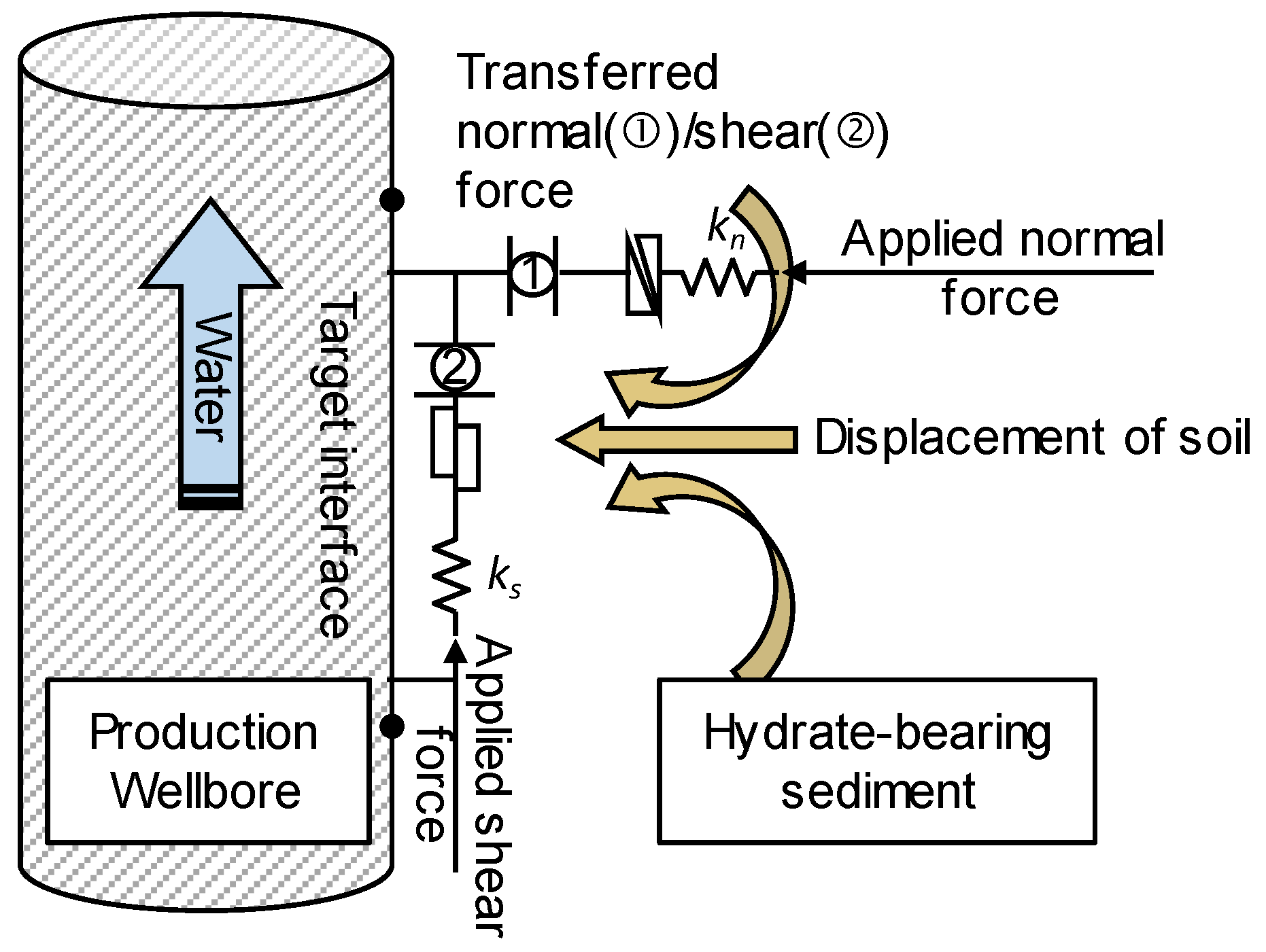
2.2.1. Concept of Force Transfer at the Interface
2.2.2. Coupling Stiffness Model in FLAC3D
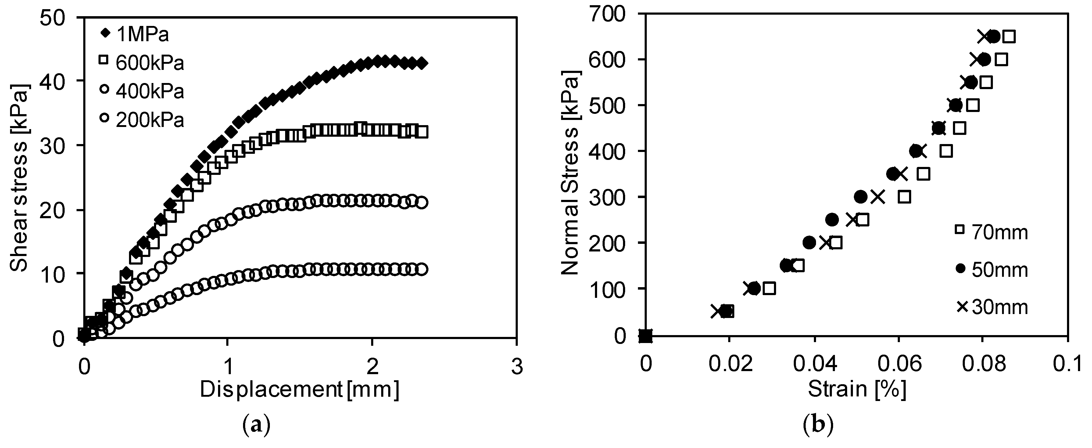
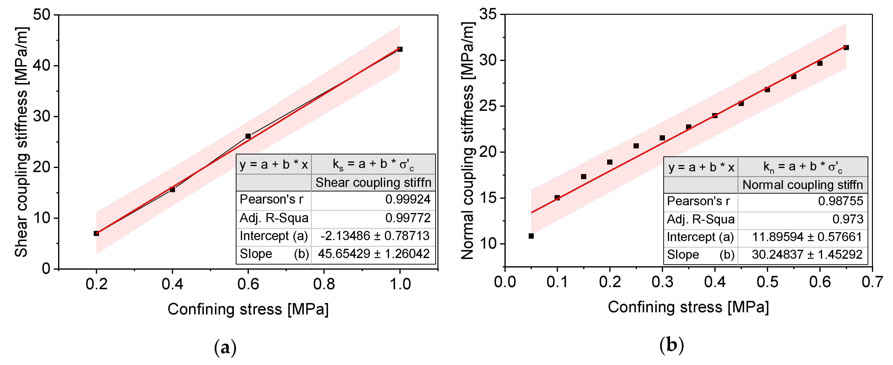
2.2.3. Linear Regression Models from Lab-Scale Experimental Tests
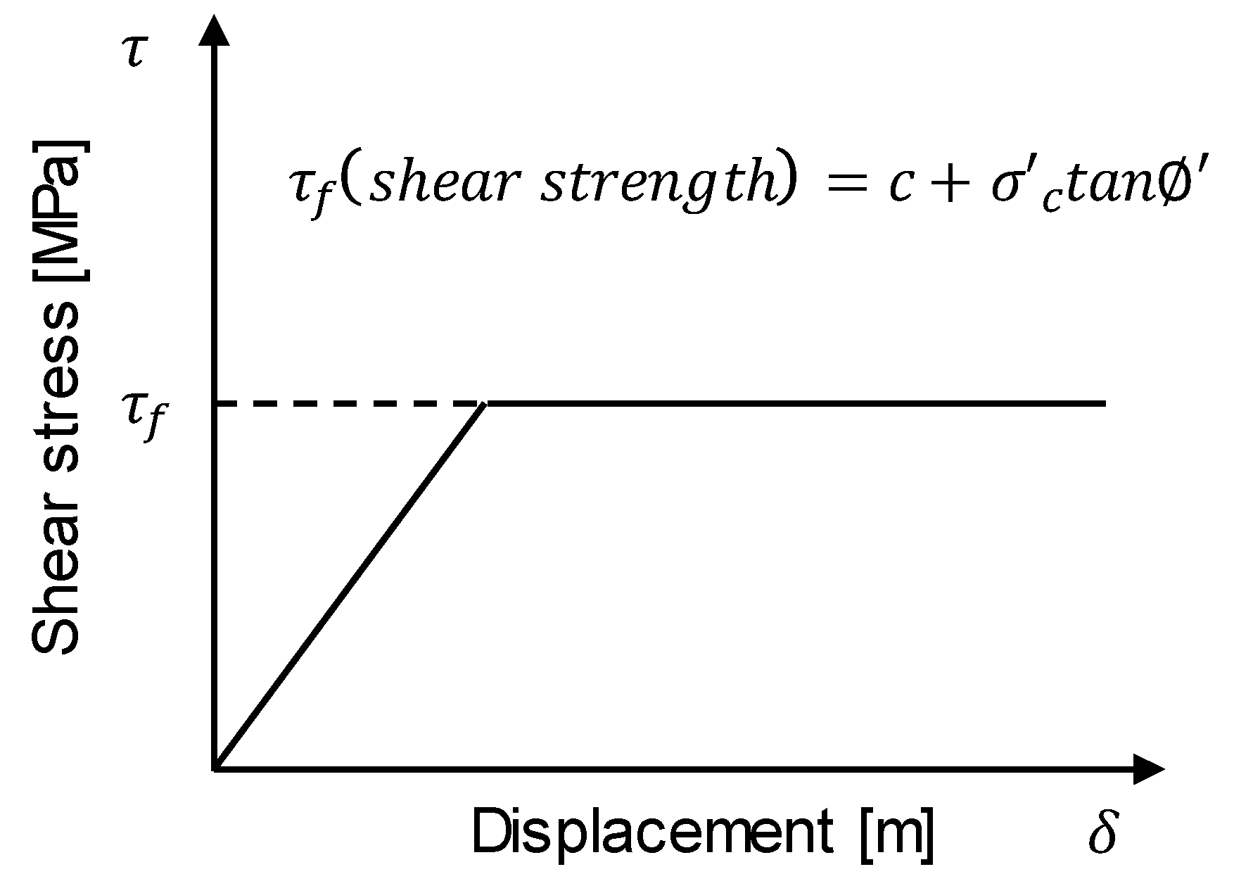
2.3. Slippage at the Interface
2.3.1. Concept of Wellbore Stress Evolution
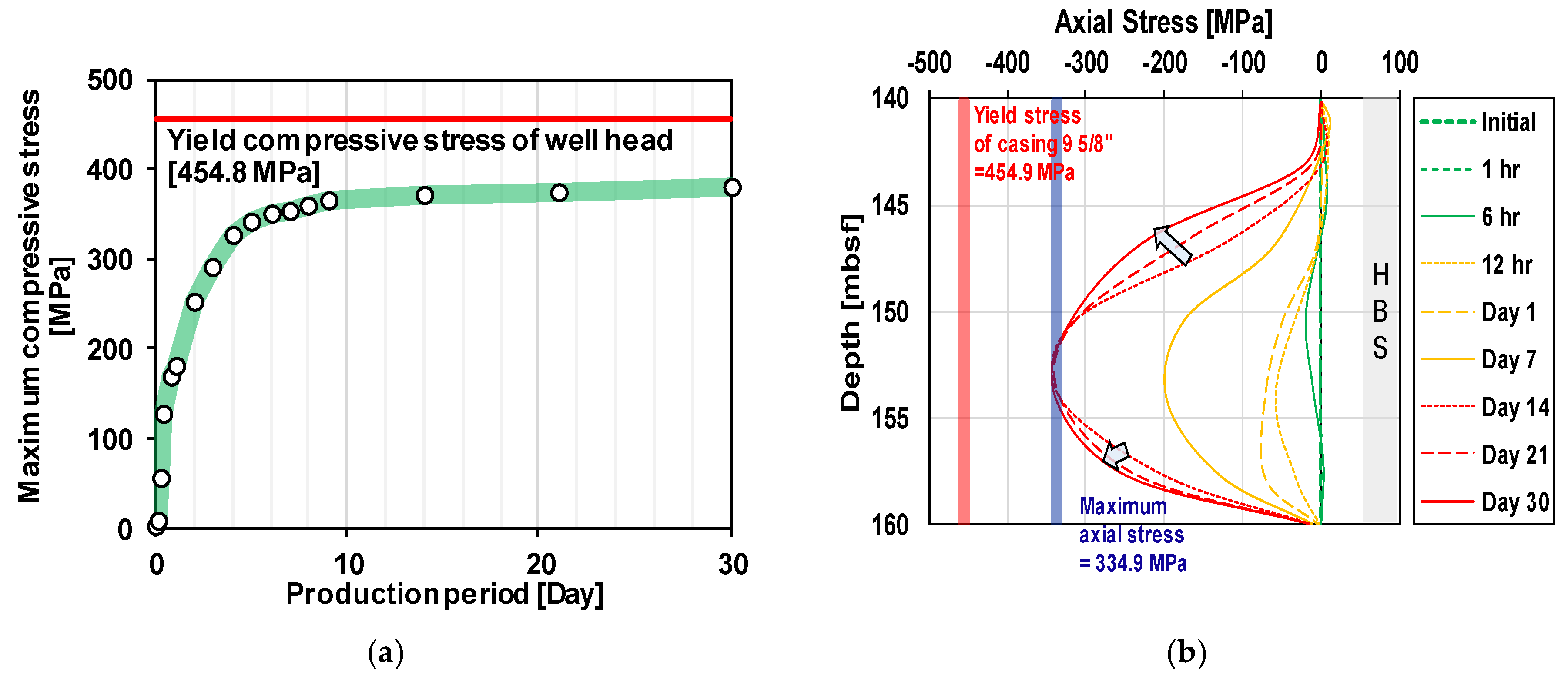
2.3.2. Maximum Axial Stress
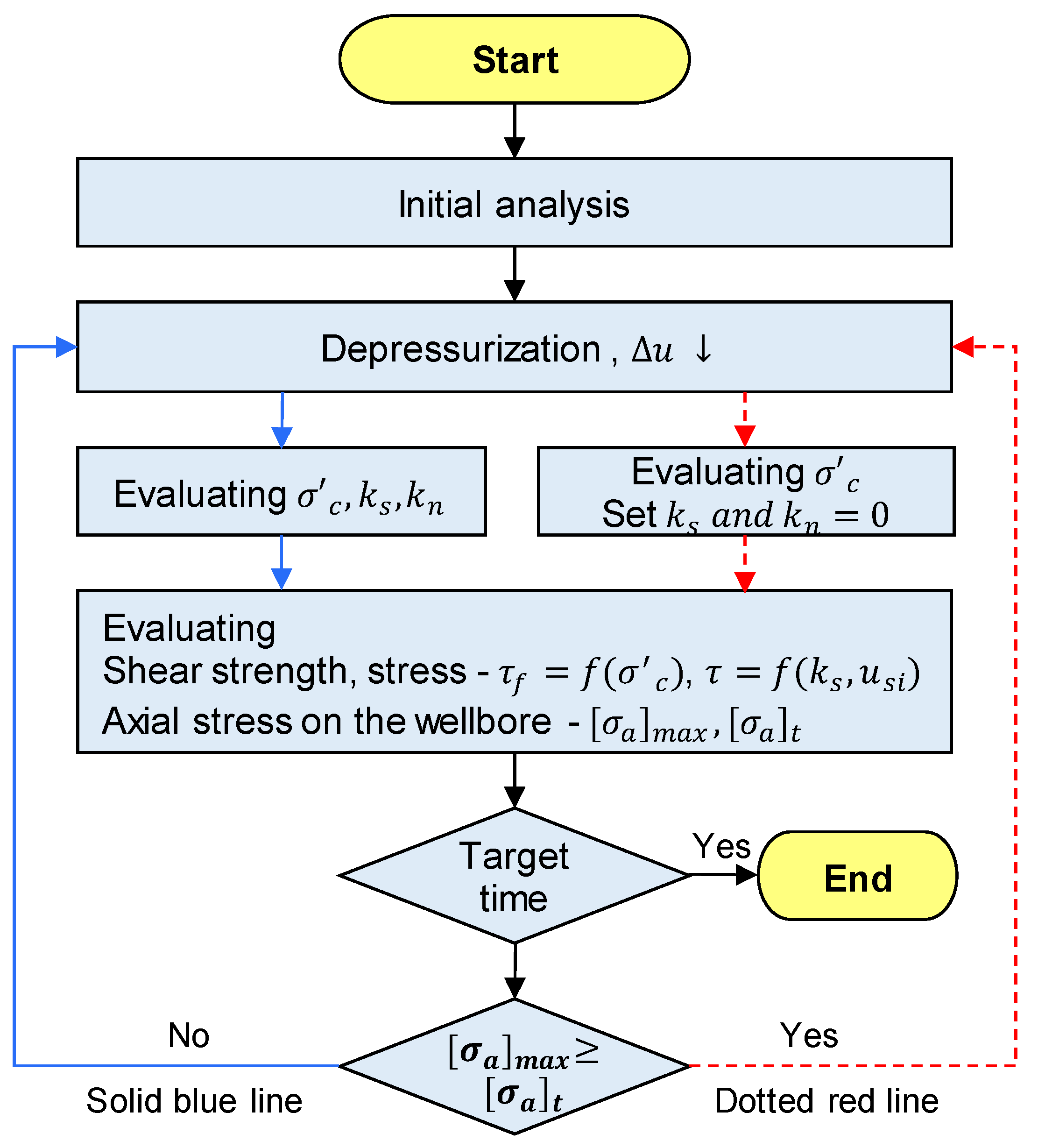
2.4. Algorithm for Stability Analysis of the Wellbore
Procedure for Estimating the Axial Stress on the Wellbore
2.5. Target Site and Input Parameters
3. Results and Analysis
3.1. Stability Analysis of HBS During Gas Hydrate Production
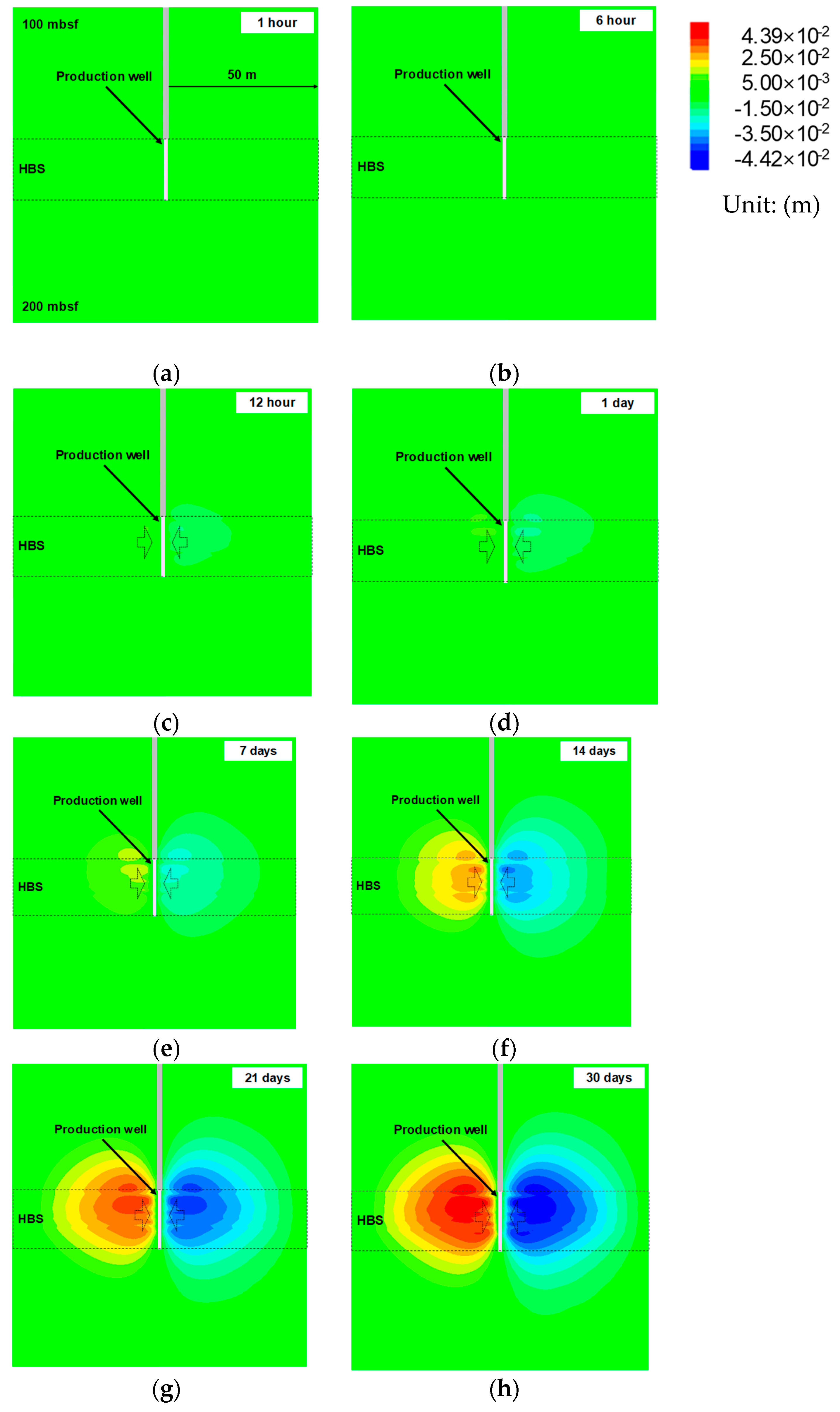
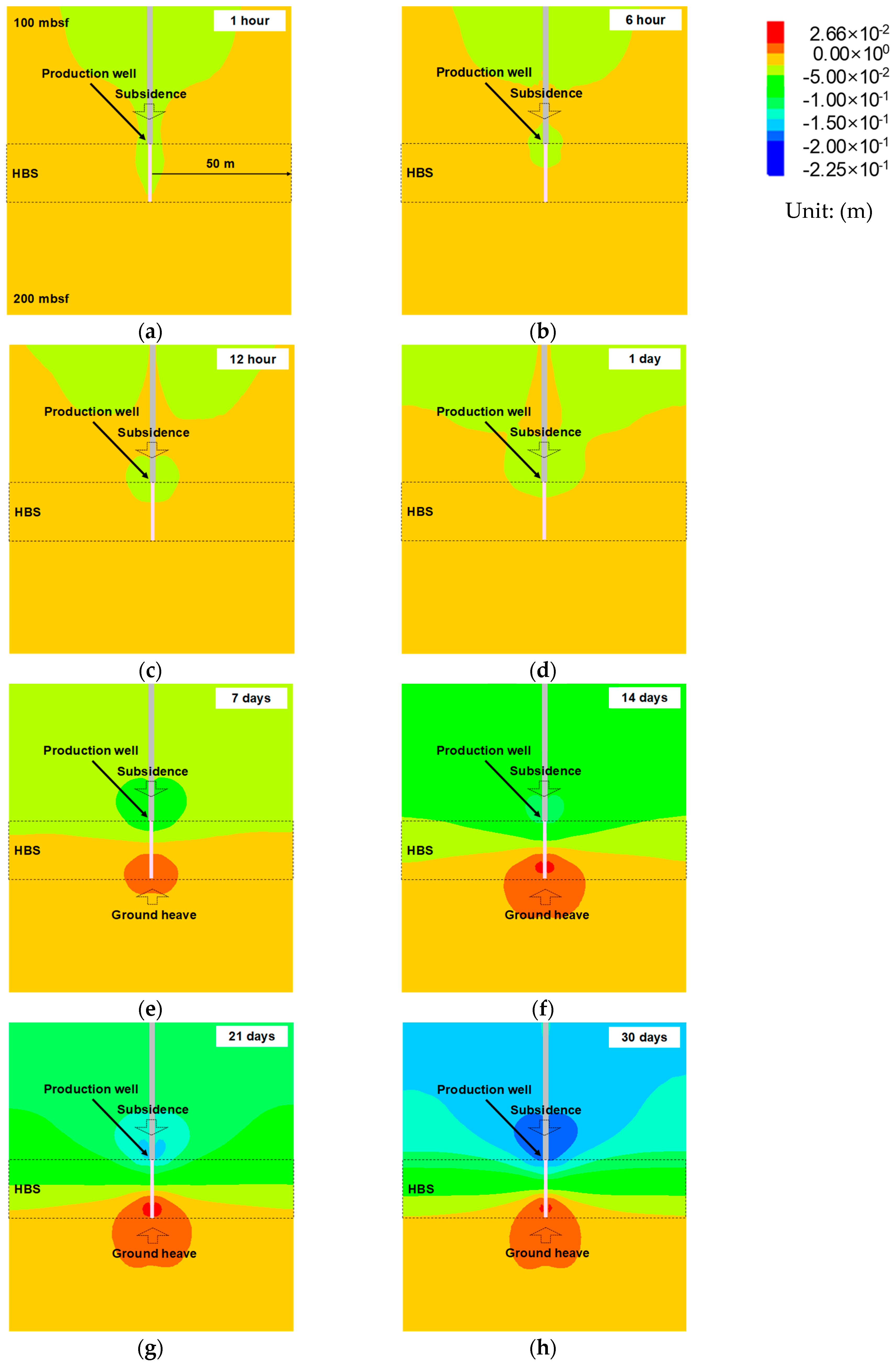
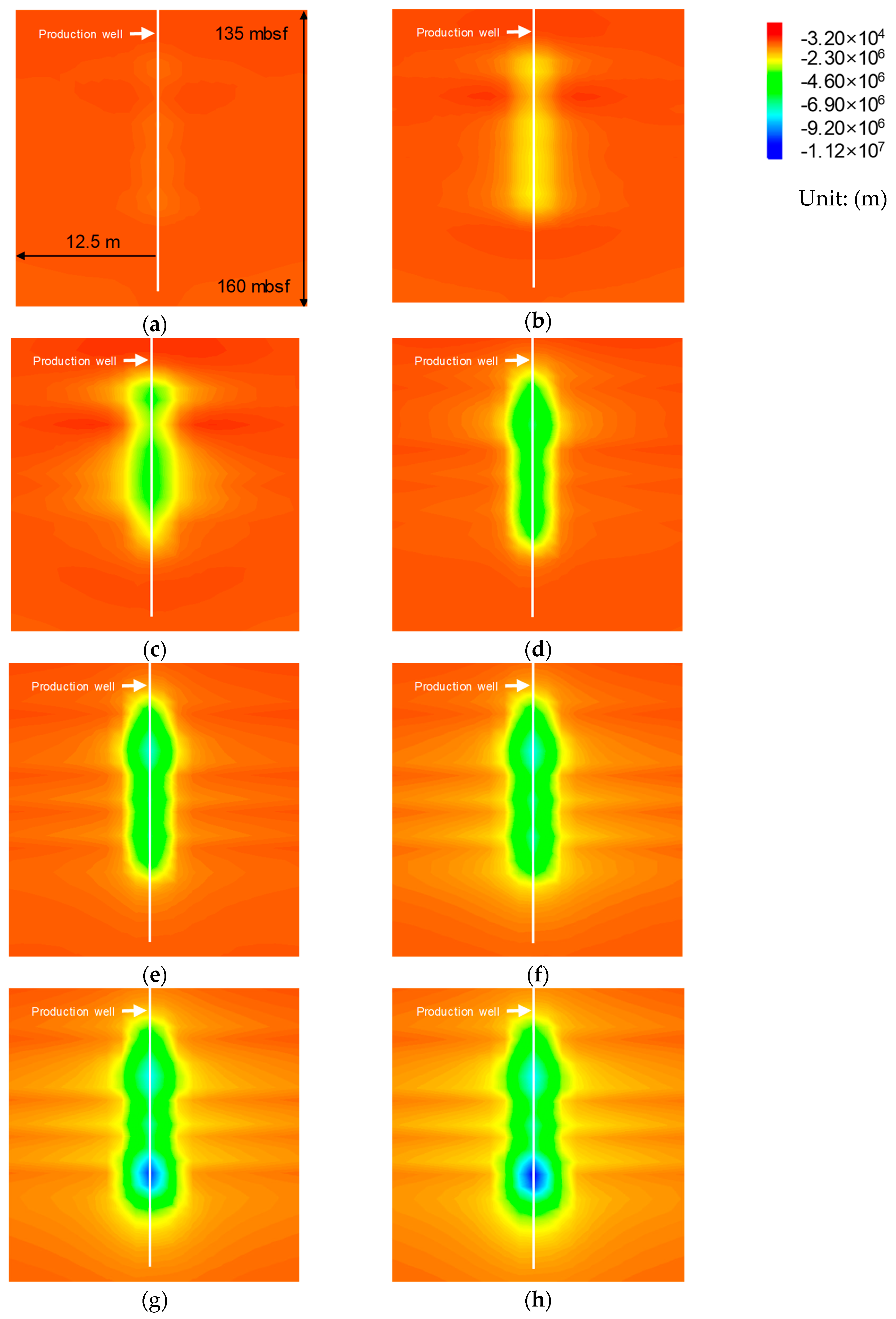
Geotechnical Behaviors Near the Wellbore During Gas Production
3.2. Effects of Coupling Stiffness and Confining Stress on Axial Stress of Wellbore
3.2.1. Parametric Analysis
3.2.2. Results of Parametric Study
3.3. Effects of Slippage at the Interface
4. Discussion
4.1. Comparison of the Models
4.2. Comparison of Results According to Model Application
5. Conclusions
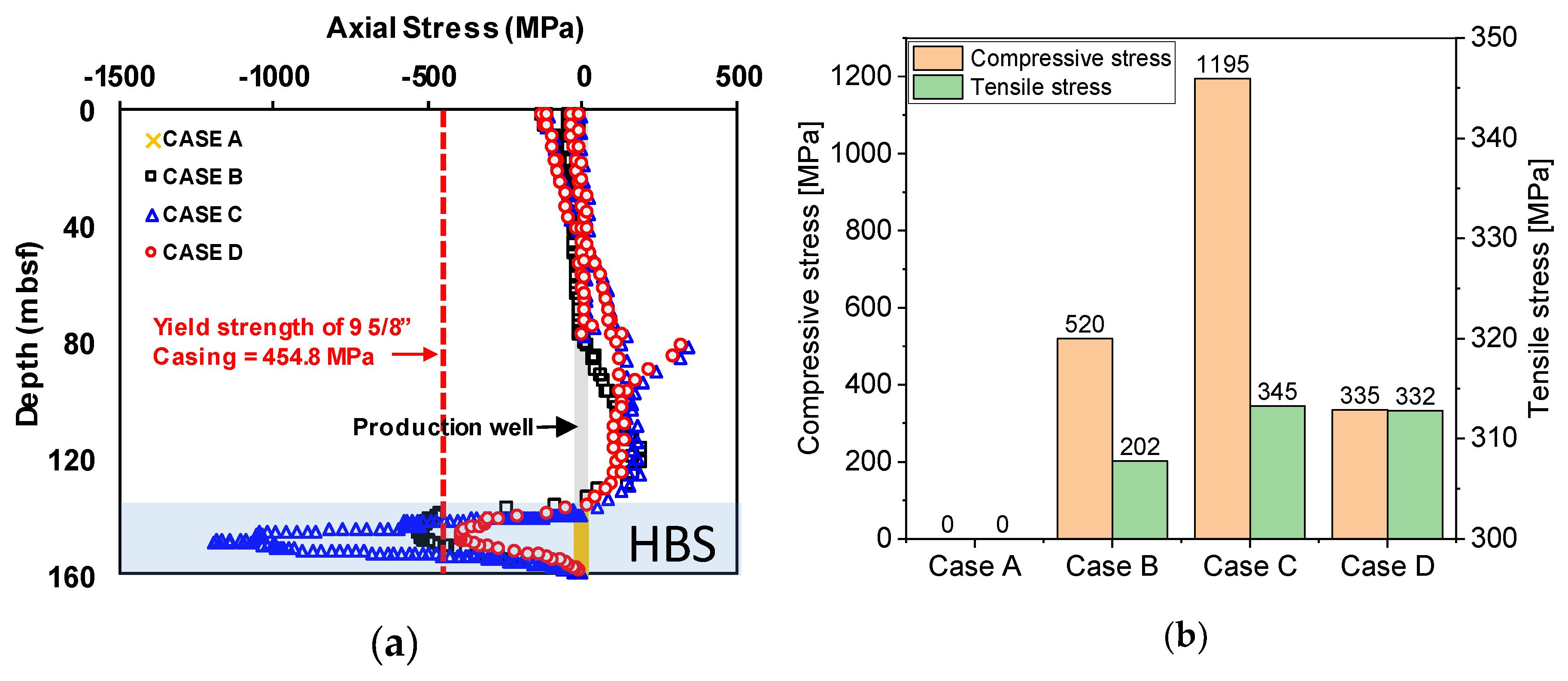
- The shear and normal coupling stiffness have to be considered to simulate the interface between the wellbore and the ground. From the parametric analysis relating coupling stiffness to wellbore stability, shear coupling stiffness has a significant effect on the development of axial stress of the wellbore while normal coupling stiffness does not affect the development of axial stress on the wellbore.
- The shear and normal coupling stiffness are the function of confining stress. This study derived a coupling stiffness model considering confining stress by performing the direct shear test and consolidation test.
- The shear coupling stiffness has to be considered differently from the depth of the wellbore to estimate the actual development of axial stress on the wellbore.
- The compressive stress is induced at the wellbore due to the subsidence and heave of the ground.
- As the effective stress with depressurization for gas hydrate production increases, slippage occurs between the wellbore and the ground because of shear failure. After shear failure, additional axial stress on the wellbore is not developed. For this reason, the maximum generated axial stress converges to a whole range during gas hydrate production.
- Preferentially, the maximum axial stress occurs at the neutral point where displacement is zero, and gradually converges to the whole range of the wellbore. The final conclusion based on the key findings is that the coupling stiffness has to be considered differently from the depth of the wellbore, and the slippage phenomena also has to be considered to performed accurate stability analysis.
Author Contributions
Funding
Conflicts of Interest
References
- Yin, Z.; Khurana, M.; Tan, H.K.; Linga, P. A review of gas hydrate growth kinetic models. Chem. Eng. J. 2018, 342, 9–29. [Google Scholar] [CrossRef]
- Chong, Z.R.; Yang, S.H.B.; Babu, P.; Linga, P.; Li, X.-S. Review of natural gas hydrates as an energy resource: Prospects and challenges. Appl. Energy 2016, 162, 1633–1652. [Google Scholar] [CrossRef]
- Sloan, E.D. Fundamental principles and applications of natural gas hydrates. Nature 2003, 426, 353. [Google Scholar] [CrossRef] [PubMed]
- Rossi, F.; Gambelli, A.M.; Sharma, D.K.; Castellani, B.; Nicolini, A.; Castaldi, M.J. Experiments on methane hydrates formation in seabed deposits and gas recovery adopting carbon dioxide replacement strategies. Appl. Therm. Eng. 2019, 148, 371–381. [Google Scholar] [CrossRef]
- Lu, H.; Seo, Y.-T.; Lee, J.-W.; Moudrakovski, I.; Ripmeester, J.A.; Chapman, N.R.; Coffin, R.B.; Gardner, G.; Pohlman, J. Complex gas hydrate from the Cascadia margin. Nature 2007, 445, 303. [Google Scholar] [CrossRef]
- Makogon, Y.F. Natural gas hydrates—A promising source of energy. J. Nat. Gas. Sci. Eng. 2010, 2, 49–59. [Google Scholar] [CrossRef]
- Park, K.-P.; Bahk, J.-J.; Kwon, Y.; Kim, G.Y.; Riedel, M.; Holland, M.; Schultheiss, P.; Rose, K. Korean national Program expedition confirms rich gas hydrate deposit in the Ulleung Basin, East Sea. Fire Ice Methane Hydrate Newsl. 2008, 8, 6–9. [Google Scholar]
- Kim, G.Y.; Yi, B.Y.; Yoo, D.G.; Ryu, B.J.; Riedel, M. Evidence of gas hydrate from downhole logging data in the Ulleung Basin, East Sea. Mar. Pet. Geol. 2011, 28, 1979–1985. [Google Scholar] [CrossRef]
- Ryu, B.-J.; Collett, T.S.; Riedel, M.; Kim, G.Y.; Chun, J.-H.; Bahk, J.-J.; Lee, J.Y.; Kim, J.-H.; Yoo, D.-G. Scientific results of the second gas hydrate drilling expedition in the Ulleung basin (UBGH2). Mar. Pet. Geol. 2013, 47, 1–20. [Google Scholar] [CrossRef]
- Kang, N.; Yoo, D.; Yi, B.; Bahk, J.; Ryu, B. Resources Assessment of Gas Hydrate in the Ulleung Basin, Offshore Korea. In Proceedings of the AGU Fall Meeting Abstracts, San Francisco, CA, USA, 3–7 December 2012. [Google Scholar]
- Lee, G.H.; Bo, Y.Y.; Yoo, D.G.; Ryu, B.J.; Kim, H.J. Estimation of the gas-hydrate resource volume in a small area of the Ulleung Basin, East Sea using seismic inversion and multi-attribute transform techniques. Mar. Pet. Geol. 2013, 47, 291–302. [Google Scholar] [CrossRef]
- Riedel, M.; Bahk, J.-J.; Kim, H.-S.; Scholz, N.; Yoo, D.; Kim, W.-S.; Ryu, B.-J.; Lee, S. Seismic facies analyses as aid in regional gas hydrate assessments. Part-II: Prediction of reservoir properties, gas hydrate petroleum system analysis, and Monte Carlo simulation. Mar. Pet. Geol. 2013, 47, 269–290. [Google Scholar] [CrossRef]
- Bo, Y.Y.; Lee, G.H.; Kang, N.K.; Yoo, D.G.; Lee, J.Y. Deterministic estimation of gas-hydrate resource volume in a small area of the Ulleung Basin, East Sea (Japan Sea) from rock physics modeling and pre-stack inversion. Mar. Pet. Geol. 2018, 92, 597–608. [Google Scholar]
- Holder, G.; Kamath, V.; Godbole, S. The potential of natural gas hydrates as an energy resource. Annu. Rev. Energy 1984, 9, 427–445. [Google Scholar] [CrossRef]
- Collett, T.; Bahk, J.-J.; Baker, R.; Boswell, R.; Divins, D.; Frye, M.; Goldberg, D.; Husebø, J.; Koh, C.; Malone, M. Methane Hydrates in Nature Current Knowledge and Challenges. J. Chem. Eng. Data 2014, 60, 319–329. [Google Scholar] [CrossRef]
- Dallimore, S.; Collett, T. Summary and implications of the Mallik 2002 gas hydrate production research well program. Sci. Results Mallik 2005, 585, 1–36. [Google Scholar]
- Yamamoto, K.; Terao, Y.; Fujii, T.; Ikawa, T.; Seki, M.; Matsuzawa, M.; Kanno, T. Operational overview of the first offshore production test of methane hydrates in the Eastern Nankai Trough. In Proceedings of the Offshore Technology Conference, Houston, TX, USA, 5–8 May 2014. [Google Scholar]
- Moridis, G.J.; Collett, T.S.; Boswell, R.; Hancock, S.; Rutqvist, J.; Santamarina, C.; Kneafsey, T.; Reagan, M.T.; Pooladi-Darvish, M.; Kowalsky, M. Gas hydrates as a potential energy source: State of knowledge and challenges. In Advanced Biofuels and Bioproducts; Springer: Berlin, Germany, 2013; pp. 977–1033. [Google Scholar]
- Moridis, G.J. TOUGH+ HYDRATE v1. 2 User’s Manual: A Code for the Simulation of System Behavior in Hydrate-Bearing Geologic Media; University of California: Berkeley, CA, USA, 2012. [Google Scholar]
- Moridis, G.; Kowalsky, M.; Pruess, K. HydrateResSim Users Manual: A Numerical Simulator for Modeling the Behavior of Hydrates in Geologic Media; Lawrence Berkeley National Laboratory: Berkeley, CA, USA, 2005. [Google Scholar]
- Kurihara, M.; Ouchi, H.; Masuda, Y.; Narita, H.; Okada, Y. Assessment of Gas Productivity of Natural Methane Hydrates Using MH21 Reservoir Simulator; Natural Gas Hydrates/Energy Resource Potential Associated Geologic Hazards: Vancouver, BC, Canada, 2004. [Google Scholar]
- White, M. Impact of kinetics on the injectivity of liquid CO2 into Arctic hydrates. In Proceedings of the OTC Arctic Offshore Technology Conference, Houston, TX, USA, 7 February 2011. [Google Scholar]
- Kim, A. THM Coupled Numerical Analysis of Gas Production from Methane Hydrate Deposits in the Ulleung Basin in Korea. Ph.D. Thesis, Korea Advanced Institute of Science and Technology (KAIST), Daejeon, Korea, 2016. [Google Scholar]
- Kim, A.-R.; Kim, J.-T.; Cho, G.-C.; Lee, J.Y. Methane Production From Marine Gas Hydrate Deposits in Korea: Thermal-Hydraulic-Mechanical Simulation on Production Wellbore Stability. J. Geophys. Res. Solid Earth 2018, 123, 9555–9569. [Google Scholar] [CrossRef]
- Masuda, Y. Modeling and experimental studies on dissociation of methane gas hydrates in Berea sandstone cores. In Proceedings of the Third International Gas Hydrate Conference, Salt Lake City, UT, USA, 18–22 July 1999. [Google Scholar]
- Kim, A.-R.; Kim, H.-S.; Cho, G.-C.; Lee, J.Y. Estimation of model parameters and properties for numerical simulation on geomechanical stability of gas hydrate production in the Ulleung Basin, East Sea, Korea. Quat. Int. 2017, 459, 55–68. [Google Scholar] [CrossRef]
- Zheng, R.; Li, S.; Li, Q.; Li, X. Study on the relations between controlling mechanisms and dissociation front of gas hydrate reservoirs. Appl. Energy 2018, 215, 405–415. [Google Scholar] [CrossRef]
- Zheng, R.; Li, S.; Li, X. Sensitivity analysis of hydrate dissociation front conditioned to depressurization and wellbore heating. Mar. Pet. Geol. 2018, 91, 631–638. [Google Scholar] [CrossRef]
- Su, Z.; Cao, Y.; Wu, N.; He, Y. Numerical analysis on gas production efficiency from hydrate deposits by thermal stimulation: Application to the Shenhu Area, south China sea. Energies 2011, 4, 294–313. [Google Scholar] [CrossRef]
- Ruan, X.; Song, Y.; Zhao, J.; Liang, H.; Yang, M.; Li, Y. Numerical simulation of methane production from hydrates induced by different depressurizing approaches. Energies 2012, 5, 438–458. [Google Scholar] [CrossRef]
- Sun, Z.; Xin, Y.; Sun, Q.; Ma, R.; Zhang, J.; Lv, S.; Cai, M.; Wang, H. Numerical simulation of the depressurization process of a natural gas hydrate reservoir: An attempt at optimization of field operational factors with multiple wells in a real 3D geological model. Energies 2016, 9, 714. [Google Scholar] [CrossRef]
- Wang, Y.; Feng, J.-C.; Li, X.-S.; Zhang, Y.; Li, G. Evaluation of gas production from marine hydrate deposits at the GMGS2-Site 8, Pearl river Mouth Basin, South China Sea. Energies 2016, 9, 222. [Google Scholar] [CrossRef]
- Ruan, X.; Li, X.-S.; Xu, C.-G. Numerical Investigation of the Production Behavior of Methane Hydrates under Depressurization Conditions Combined with Well-Wall Heating. Energies 2017, 10, 161. [Google Scholar] [CrossRef]
- Feng, Y.; Chen, L.; Suzuki, A.; Kogawa, T.; Okajima, J.; Komiya, A.; Maruyama, S. Numerical analysis of gas production from layered methane hydrate reservoirs by depressurization. Energy 2019, 166, 1106–1119. [Google Scholar] [CrossRef]
- Jeong, S.; Lee, J.; Lee, C.J. Slip effect at the pile-soil interface on dragload. Comput. Geotech. 2004, 31, 115–126. [Google Scholar] [CrossRef]
- Chen, R.; Zhou, W.; Chen, Y. Influences of soil consolidation and pile load on the development of negative skin friction of a pile. Comput. Geotech. 2009, 36, 1265–1271. [Google Scholar] [CrossRef]
- Abdrabbo, F.M.; Ali, N.A. Behaviour of single pile in consolidating soil. Alex. Eng. J. 2015, 54, 481–495. [Google Scholar] [CrossRef]
- Itasca, F.D. Fast lagrangian analysis of continua in 3 dimensions; Itasca Consulting Group Inc.: Minneapolis, MN, USA, 2005. [Google Scholar]
- Häggblad, B.; Nordgren, G. Modelling nonlinear soil-structure interaction using interface elements, elastic-plastic soil elements and absorbing infinite elements. Comput. Struct. 1987, 26, 307–324. [Google Scholar] [CrossRef]
- Kim, J.; Moridis, G.J.; Rutqvist, J. Coupled flow and geomechanical analysis for gas production in the Prudhoe Bay Unit L-106 well Unit C gas hydrate deposit in Alaska. J. Pet. Sci. Eng. 2012, 92, 143–157. [Google Scholar] [CrossRef]
- Rutqvist, J.; Moridis, G.; Grover, T.; Silpngarmlert, S.; Collett, T.; Holdich, S. Coupled multiphase fluid flow and wellbore stability analysis associated with gas production from oceanic hydrate-bearing sediments. J. Pet. Sci. Eng. 2012, 92, 65–81. [Google Scholar] [CrossRef]
- Kamath, V.A. Study of Heat Transfer Characteristics During Dissociation of Gas Hydrates in Porous Media; Pittsburgh University: Pittsburgh, PA, USA, 1984. [Google Scholar]
- Clarke, M.; Bishnoi, P.R. Determination of the activation energy and intrinsic rate constant of methane gas hydrate decomposition. Can. J. Chem. Eng. 2001, 79, 143–147. [Google Scholar] [CrossRef]
- Darcy, H.P.G. Les Fontaines Publiques de la Ville de Dijon. Exposition et Application des Principes à Suivre et des Formules à Employer dans les Questions de Distribution d’eau; Dalamont, V., Ed.; Libraire des Corps Imperiaux des Ponts et Chaussees et des Mines: Paris, France, 1856. [Google Scholar]
- Van Genuchten, M.T. A closed-form equation for predicting the hydraulic conductivity of unsaturated soils 1. Soil Sci. Soc. Am. J. 1980, 44, 892–898. [Google Scholar] [CrossRef]
- Zeghal, M.; Edil, T.B. Soil structure interaction analysis: Modeling the interface. Can. Geotech. J. 2002, 39, 620–628. [Google Scholar] [CrossRef]
- Salemi, A.; Esmaeili, M.; Sereshki, F. Normal and shear resistance of longitudinal contact surfaces of segmental tunnel linings. Int. J. Rock Mech. Min. Sci. 2015, 77, 328–338. [Google Scholar] [CrossRef]
- Rosso, R.S. A comparison of joint stiffness measurements in direct shear, triaxial compression, and In Situ. Int. J. Rock Mech. Min. Sci. Geomech. Abstr. 1976, 13, 167–172. [Google Scholar] [CrossRef]
- Li, W.; Bai, J.; Cheng, J.; Peng, S.; Liu, H. Determination of coal–rock interface strength by laboratory direct shear tests under constant normal load. Int. J. Rock Mech. Min. Sci. 2015, 77, 60–67. [Google Scholar] [CrossRef]
- Jeong, S.; Cho, J. Proposed nonlinear 3-D analytical method for piled raft foundations. Comput. Geotech. 2014, 59, 112–126. [Google Scholar] [CrossRef]
- Kulhawy, F.H. Stress deformation properties of rock and rock discontinuities. Eng. Geol. 1975, 9, 327–350. [Google Scholar] [CrossRef]
- Bandis, S.C.; Lumsden, A.C.; Barton, N.R. Fundamentals of rock joint deformation. Int. J. Rock Mech. Min. Sci. Geomech. Abstr. 1983, 20, 249–268. [Google Scholar] [CrossRef]


| Property | Conductor | 20-in. Casing | 13-3/8-in. Casing | 9-5/8-in. Casing | 9-5/8-in. Casing Screen Part | Cement Grout |
|---|---|---|---|---|---|---|
| Diameter (inch) | 36 | 20 | 13.375 | 9.625 | 9.625 | - |
| Thickness (inch) | 1.5 | 1 | 0.514 | 0.472 | 0.472 | - |
| Elastic modulus (GPa) | 200 | 200 | 200 | 200 | 120 | 3.47 |
| Density (kg/m3) | 7897 | 7897 | 7897 | 7897 | 7897 | 1040 |
| Yield strength (MPa) | 390 | 390 | 758 | 758 | 454.8 | 1.74 |
| Cohesion (MPa) | - | - | - | - | - | 17.39 |
| Friction angle (deg) | - | - | - | - | - | 30 |
| Category | Parameters | Value | Category- | Parameters | Value |
|---|---|---|---|---|---|
| Geologic conditions | Hydrostatic pressure at seafloor (MPa) | 21.9 | Mechanical properties | Bulk density of sand (Layer S; kg/m3) | 1700 |
| - | Temperature at seafloor (°C) | 0.482 | Bulk density of mud (Layer M1; kg/m3) | 1500 | |
| - | Geothermal gradient (°C/km) | 112 | Bulk density of mud (Layer M2; kg/m3) | 1610 | |
| - | Hydrate occurrence zone (mbsf) | 140–153 | - | Bulk density of mud (Layer M3; kg/m3) | 1640 |
| - | Initial hydrate saturation in sand (Layer S; %) | 65 | - | Methane hydrate density (kg/m3) | 910 |
| - | Initial hydrate saturation in mud (%) | 0.0 | - | Young’s modulus of sand (Layer S; MPa) | 40 |
| - | Salinity (wt%) | 3.45 | - | Young’s modulus of mud (Layer M1; MPa) | 15 |
| Thermal properties | Thermal conductivity of sand (W/m K) | 1.45 | - | Young’s modulus of mud (Layer M2; MPa) | 18 |
| - | Thermal conductivity of mud (W/m K) | 1.00 | - | Young’s modulus of mud (Layer M3; MPa) | 20 |
| Hydraulic properties | Porosity of sand (Layer S; -) | 0.45 | - | Poisson’s ratio of sand (Layer S; -) | 0.25 |
| - | Porosity of mud (Layer M1; -) | 0.69 | - | Poisson’s ratio of mud (Layer M1, M2, and M3; -) | 0.35 |
| - | Porosity of mud (Layer M2; -) | 0.67 | - | Friction angle of sand (Layer S; deg) | 25 |
| - | Porosity of mud (Layer M3; -) | 0.63 | - | Friction angle of mud (Layer M1, M2, and M3; deg) | 22 |
| - | Residual water saturation, (-) | 0.1 | - | Cohesion of sand (Layer S; kPa) | 35 |
| - | Residual gas saturation, (-) | 0.01 | - | Cohesion of mud (Layer M1, M2; kPa) | 30 |
| - | - | - | - | Cohesion of mud (Layer M3; kPa) | 40 |
| Van Genuchten parameters | P0 (kPa) | 2.2 | Properties related to the hydrate dissociation | Molecular mass of gas, Mg (g/mol) | 16.042 |
| a | 0.6 | Molecular mass of water, Mw (g/mol) | 18.016 | ||
| b | 0.5 | Molecular mass of hydrate, Mh (g/mol) | 124.14 | ||
| - | c | 0.5 | Hydrate number, Nh | 6 | |
| - | - | - | Phase equilibrium model parameters, α, β | 42.047, −9332 |
| Case | Normal Coupling Stiffness, kn (Pa/m) | Shear Coupling Stiffness, ks (Pa/m) | Description |
|---|---|---|---|
| I | 57.41 106 | 26.11 106 | Experimental data |
| II | 5.74 106 | 26.11 106 | 1/10 kn compared to case I |
| III | 28.71 106 | 2.61 106 | 1/2 kn and 1/10 ks compared to case I |
| IV | 57.41 106 | 2.61 106 | 1/10 ks compared to case I |
| V | Consider confining stress |
| Case | Coupling Stiffness Model | Slippage at Interface | Production Period |
|---|---|---|---|
| A | w/o consideration | w/o consideration | 14 days |
| B | With consideration FLAC3D (constant) | w/o consideration | 14 days |
| C | With consideration the confinement dependent model (this study) | w/o consideration | 14 days |
| D | with consideration | 14 days |
© 2019 by the authors. Licensee MDPI, Basel, Switzerland. This article is an open access article distributed under the terms and conditions of the Creative Commons Attribution (CC BY) license (http://creativecommons.org/licenses/by/4.0/).
Share and Cite
Kim, J.-T.; Kim, A.-R.; Cho, G.-C.; Kang, C.-W.; Lee, J.Y. The Effects of Coupling Stiffness and Slippage of Interface Between the Wellbore and Unconsolidated Sediment on the Stability Analysis of the Wellbore Under Gas Hydrate Production. Energies 2019, 12, 4177. https://doi.org/10.3390/en12214177
Kim J-T, Kim A-R, Cho G-C, Kang C-W, Lee JY. The Effects of Coupling Stiffness and Slippage of Interface Between the Wellbore and Unconsolidated Sediment on the Stability Analysis of the Wellbore Under Gas Hydrate Production. Energies. 2019; 12(21):4177. https://doi.org/10.3390/en12214177
Chicago/Turabian StyleKim, Jung-Tae, Ah-Ram Kim, Gye-Chun Cho, Chul-Whan Kang, and Joo Yong Lee. 2019. "The Effects of Coupling Stiffness and Slippage of Interface Between the Wellbore and Unconsolidated Sediment on the Stability Analysis of the Wellbore Under Gas Hydrate Production" Energies 12, no. 21: 4177. https://doi.org/10.3390/en12214177
APA StyleKim, J.-T., Kim, A.-R., Cho, G.-C., Kang, C.-W., & Lee, J. Y. (2019). The Effects of Coupling Stiffness and Slippage of Interface Between the Wellbore and Unconsolidated Sediment on the Stability Analysis of the Wellbore Under Gas Hydrate Production. Energies, 12(21), 4177. https://doi.org/10.3390/en12214177