Article

Energy-Storage-Based Smart Electrical Infrastructure and Regenerative Braking Energy Management in AC-Fed Railways with Neutral Zones

School of Mechanical Electronic & Information Engineering, China University of Mining & Technology (Beijing), Beijing 100083, China
*
Author to whom correspondence should be addressed.
Energies 2019, 12(21), 4053; https://doi.org/10.3390/en12214053
Submission received: 22 September 2019 / Revised: 20 October 2019 / Accepted: 22 October 2019 / Published: 24 October 2019
(This article belongs to the Special Issue Optimal Control of Hybrid Systems and Renewable Energies)

Abstract

:
This paper presents a modified power supply system based on the current alternating current (AC)-fed railways with neutral zones that can further improve the eco-friendliness and smart level of railways. The modified system complements the existing infrastructure with additional energy-storage-based smart electrical infrastructure. This infrastructure comprises power electronic devices with energy storage system connected in parallel to both sides of each neutral zone in the traction substations, power electronic devices connected in parallel to both sides of each neutral zone in section posts, and an energy management system. The description and functions of such a modified system are outlined in this paper. The system allows for the centralized- and distributed-control of different functions via an energy management system. In addition, a control algorithm is proposed, based on the modified system for regenerative braking energy utilization. This would ensure that all the regenerative braking energy in the whole railway electrical system is used more efficiently. Finally, a modified power supply system with eight power supply sections is considered to be a case study; furthermore, the advantages of the proposed system and the effectiveness of the proposed control algorithm are verified.

Graphical Abstract

1. Introduction

Rail transport is one of the most environmental friendly modes for transportation. Under the background of an environmentally concerned economy, it is a crucial way to satisfy increasing transport demands [1]. However, despite its high efficiency, the rail industry is still a significant energy consumer worldwide [1]. With a growing population and energy usage, the increased demand placed on rail services will further increase and the energy consumption will increase accordingly [2]. Along with the energy shortage and global warming, policy makers pay special attention to the high level of energy demand users. Due to the vast potential of energy recovery lying behind them, the targets of reduction of carbon emission and energy consumption can be achieved by regulating their energy consumption [3]. The energy savings in rail transport will play an important role in achieving this target. In rail transport, the consumption of traction energy accounts for about 60% to 80% of the total energy consumption [1]. Therefore, the regulation for traction energy will be a key area for energy savings.
To satisfy the specified energy efficiency targets, several measures have been proposed to save traction energy. Currently, the main measures for savings based on the existing technologies include renewable energy system, efficient driving, and regenerative braking.
The installation of equipment that provide clean energy from renewable sources (e.g., solar panels and wind generators) to feed the traction loads in rail may have a significant impact in the energy costs and CO2 emissions of a railway system, increasing the environment friendliness of the railway [4,5,6]. The introduction of renewable energy is to partially reduce the depletion of non-renewable energy resources and thus reduce CO2 emissions. These outcomes have been favored by scholars and many countries, such as North American, European, China, and Japan [6,7]. But in practice, the traction energy consumption of railways has not been reduced.
By contrast, the efficient driving and regenerative braking schemes differ the renewable energy scheme. They can essentially reduce the traction energy consumption of railways.
Efficient driving is an effective way to reduce the traction energy consumption of rolling stock. Typically, the running state of vehicles comprises three phases: braking, speed-holding (cruising) and acceleration. At present, many literatures have studied the efficient driving and realize the traction energy savings through the optimum combination of these phases [8,9,10,11,12,13]. To implement such trajectories and maximize savings, some auxiliary systems, such as driver advisory systems (DAS) [10,11] and automatic train operation (ATO) [12,13], must be provided to drivers. The trials of such systems have shown savings of 5‒18%. However, with efficient driving, the savings of energy consumption may sacrifice service quality, such as the train speed, stopping time, etc. [1].
Regenerative braking energy (RBE) recovery is a simple and efficient way to reduce energy consumption, which cannot influence the operation of trains and service quality. Regenerative braking is a technology that can recover the mechanical energy during a locomotive braking as electricity. In some cases, over a third of the total traction energy, even a half, can be recovered using this method. If this part of energy is used effectively, the traction energy consumption of a network will be significantly reduced [1]. There are some mature RBE utilization schemes in metro, but the metro and alternating current (AC) railways are different in some respects, such as the type of power supply voltage, the amount of traction power and so on. Therefore, the RBE recovery equipment in the metro cannot be used directly in AC railway systems, but the metro schemes can be used as reference. According to experience of the metro systems and the art of research, the main regenerative energy saving measures are: a reversible inverter, optimizing operation timetable, energy storage system, and power transfer device.
Reversible inverter can directly inject the RBE into the public grid or distribution grid. Conventionally, the RBE is reversed from the traction power supply system to the public grid via traction transformers at substations. However, it is not reflected to the electric charge purchased from a utility company for railway operation [14]. Furthermore, it is not certain that the back-flown regenerative power is effectively utilized. Due to the single-phase characteristics of the back-flown power, it may be consumed in the traction transformers as a circulation current or as a heat [15]. In addition, the back-flown regenerative power, due to its stochasticity, may have impacts on the public grid.
Another option is to inject the RBE into the distribution grid via a regenerative inverter to power the distribution load in railway power supply systems, such as lighting, air conditioning, elevators, escalators, and so on. However, the distribution power of a conventional railway station on the ground is considerably smaller than the regenerative power [16]. Therefore, the RBE would be surplus, flowing back to the public grid or being stored in an energy storage system.
Optimizing operation timetable is a low-cost solution for reducing energy consumption of railways by increasing the coexistence time of the traction and braking trains in the same electric section without auxiliaries [1,17,18]. However, owing to unanticipated occurrences often emerging during the actual operation, such as the temporary addition or cancellation of trains, equipment failure, bad weather, and so on, the trains cannot consistently run according to the optimized operation timetable. This leads to a significant reduction in energy saving efficiency. Furthermore, the flexibility of this solution is poor [19].
The other option is to store the RBE in an energy storage system (ESS), by which the RBE can be utilized or sold at some point in the future. ESS can be generally divided into on-board and wayside ESS. The first standard related to railway ESS, IEC62924, was published in 2017 and it will provide guidance for the application of ESS in railway [20]. According to the measured data in the railway systems in Japan, the total energy saving effect can amount to several hundred MWh per year after applying ESS. If the ESS is installed in the appropriate location, the total traction energy consumption can be reduced by about 4‒8% [21]. In realizing railway energy saving and consumption reduction, it will bring huge electricity savings to railway operation. However, this data was obtained from the Japanese direct current (DC) railway traction system; according to present reports, the installation of ESS is usually only in DC traction systems or metros. Actual cases of installing such energy storage devices in AC systems are seldom reported.
In the AC railway system, an application of RBE utilization is the use of a railway static power conditioner (RPC). By using it, the regenerative braking power can be interchanged from one supply section to an adjacent one. At present, a RPC was installed at Ushiku section post in Japan in 2014 [14]. At first, the development of RPC was to solve the three phase imbalance problem at traction substations. Then, with the emergence of RBE utilization problem, RPCs were used to improve the utilization of RBE. The capacity of RPCs for utilizing RBE can be much smaller than that of three phase balancing, but they have much potential to increase the environment friendliness of the AC railway systems by making use of regenerative braking power [22]. Other than that, many papers also put forward proposals for using power transfer devices (PTD; RPC [14,22], railway power quality compensator (RPQC) [23], or energy optimization controller (EOC) [24]) to utilize the RBE.
However, the above schemes are independent distributed control and cannot cooperate with each other, which causes each device to not effectively play its maximum potential and may even cause energy waste. The railway smart grid paradigm provides a chance to integrate each component, including renewable energy systems, energy storage systems, RBE utilization systems, and so on, using bidirectional communication equipment and advanced computational features [25,26,27,28,29]. Different optimal strategies are proposed to decrease the energy consumption and electricity bills of electrical railway systems by controlling cooperative operations between each component [5,6,30,31,32]. These methods achieve the optimal operation of the electric railway energy systems using existing electrical railway infrastructure. However, there is a neutral zone (NZ) in the existing traction power supply system, which limits energy optimization capability. Thus, [33] introduced the smart electrical infrastructure into railway systems to complement the existing electrical railway infrastructure, creating more opportunities and controllability for smart railway systems, such as power flow in the whole railway system (similar to power routing). The smart grid concept presents more efficient, safe, reliable, and modernized railway systems and offers a new perspective to the eco-friendliness of railway systems and low carbon societies in the future.
This paper presents the energy-storage-based smart electrical infrastructure to modify current AC-fed railways with neutral zones. Compared with the smart electrical infrastructure in [33], the proposed modified system increases the dimensions of the controlled variables of power flow under the action of ESS. It brings more benefits, such as further enhancing the ability to control power flow and reducing more cost; achieving full utilization of all RBE, which is crucial in further improving the eco-friendliness of railway transportation; and better regulating the clean power from renewable energy sources (photovoltaic (PV) panels and wind turbines) to achieve more efficient utilization of clean energy in railways. In addition, the proposed modified system also has other functions, such as cutting peak and filling valley, active control for line voltage and emergency power supply in case of power failure. Then, in order to utilize the RBE, this paper also proposed a control algorithm to achieve the full utilization of all RBE by the use of the proposed energy-storage-based smart electrical infrastructure. It should be emphasized that when realizing the utilization of RBE, the capacity and cost of the energy storage system in the proposed modified system will be much less than that of the system adopting ESS alone; this is verified in the validation section of the paper. The work done in this paper will provide options for railway smart control and energy saving and consumption reduction.
This paper is organized as follows: The regenerative braking energy utilization schemes are described in Section 2. The description and functions of the modified system are outlined in Section 3. The proposed control algorithm based on the modified system for regenerative braking energy utilization is presented in Section 4. The verification results and analysis are represented in Section 5. Finally, conclusions are drawn in Section 6.

2. Regenerative Braking Energy Utilization Schemes

Figure 1 summarizes some possible solutions for RBE utilization that have already used or proposed. As shown in Figure 1a, regenerative resistance has been one of the most effective methods in the past, but the RBE is not utilized in this solution. A simple scheme is reversing the regenerative power from a railway power supply system to the utility grid directly, as shown in Figure 1b. However, it is not known that such back-flowed single phase regenerative power is utilized properly in the utility grid and the back-flow of power is not reflected in electrical cost. Back-flow to the distribution grid shown in Figure 1c is one of the most effective methods to utilize RBE in metros because the load of metro stations is large enough to utilize the regenerative power simultaneously. However, in AC railways such as high-speed or burden, typically the regenerative power is more than the power demand of distribution grids such as railway stations and trackside signaling systems. Therefore, whether this scheme can be used in AC railways still needs further discussion. Compared with the above solutions, the installation of ESS could be effective because it is independent of operation schedules of trains and other electrical loads, as shown in Figure 1d. The ESS can be installed along the railway trackside to store RBE. Then, the RBE stored in ESS during train braking will be utilized for the powering of systems later. However, the cost of ESS needs to be concerned in AC railways. Figure 1e shows an RBE utilization scheme via the use of a PTD (such as RPC [14] or EOC [24]) connected in parallel to both sides of each NZ in section posts (SPs). PTD can interchange regenerative power from one feeder catenary to another and it contributes to realize the simultaneous utilization of RBE within the railway systems. Figure 1f illustrates the RBE utilization scheme via the use of a PTD (such as RPQC [23] or RPC [22]) connected in parallel to both sides of each NZ in traction substations (TSs). Then, part of the traction power in one feeding section can be supplied by the RBE recovered from the other adjacent feeding section, similar to Figure 1e. Figure 1g illustrates the scheme that complements the existing railway power supply system with additional PTDs [33]. This makes it possible for control of power flow through the whole railway system. In AC railways, PTDs are able to transfer the power specified by a control system from one feeding section to the other nonadjacent electrical sections. Since the supplied power voltage is high enough, 20 kV or 25 kV, the regenerative power can be delivered over long distances, which is impossible with DC railway or metro [15].
However, as shown in Figure 1e,f, if there are no traction locomotives in the adjacent feeding section, the regenerative power flows back into the utility grid. The schemes in Figure 1g can solve this problem to a certain degree by transferring the surplus regenerative power to the traction locomotives in the other nonadjacent electrical sections. However, if the amount of regenerative power is more than the traction power in the whole railway system, the surplus regenerative power flows back into the utility grid. Therefore, to solve these problems, the installation of PTD with the ESS (EPTD) is a feasible option [34,35,36,37,38]. Via EPTD, it is possible to interchange RBE with the adjacent feeding sections when there are traction locomotives present and store the RBE when there is a surplus. Figure 2 shows the proposed energy-storage-based smart electrical infrastructure for AC-fed railways with NZs. The proposed modified system links the whole railway power supply system together by PTDs and EPTDs, allowing power flow, energy storage, and release within the internal railway system. Moreover, the modified system can not only use RBE, but also can also use clean energies and control their cooperation. Other than these, the proposed modified system also has other functions as follows:
  • Power quality improvement;
  • Peak cutting and valley filling;
  • Active control for line voltage;
  • Emergency power supply.
The following discussion covers the analysis of each function of the proposed system.

3. Description of the Modified System

The railway traction system with energy-storage-based smart electrical infrastructure is shown in Figure 3. The red dashed line is the existing infrastructure in AC-fed railways with NZs. For the sake of analysis, all locomotives on the same power supply section are equivalent to one electrical locomotive load. The existing system consists of n TSs, where TSm (m = 1, 2, …, n) is used to supply trains Lk (k = 1, 2, …, 2n) in the power supply sections Sk. The NZ is used to ensure electrical insulation between two adjacent power supply sections. The green dashed line is the proposed energy-storage-based smart electrical infrastructure. The modified system consists of the additional PTDs and EPTDs connected in parallel to both sides of each NZ and an energy management system (EMS). The acronym TS-EPTD refers to the PTDs with the ESS located in the NZs of the TSs. The acronym SP-PTD refers to the PTDs located in the other NZs of the SPs. The installation of TS-EPTDs will connect all power supply sections to ESSs, so there is no need to install EESs in SP-PTDs. The active and reactive power transferred by PTDs and EPTDs is specified by the EMS via the bidirectional communication equipment. The modified system can perform a centralized and a distributed-control. The centralized architecture can perform a global optimization to achieve the cooperative operations between each component, significantly enhancing the energy-management performance of the systems. The distributed control can further enhance redundancy and reliability of the railway systems [31,33]. Each EPTD and PTD can realize data acquisition (DA) of voltage and current on each power supply section and transmit the data to the EMS via the bidirectional communication equipment. The EMS performs a global optimization by the use of the data of voltage and current and has power control (PC) over the EPTDs and PTDs via the bidirectional communication equipment. It should be pointed out that the proposed system is also applicable for autotransformer (AT)-based railway systems.

3.1. Regenerative Braking Energy Utilization

The simplified system and its electrical description are shown in Figure 4. uk and ik are the voltage and current on each power supply section provided by traction transformers, iL,k is the load current produced by locomotives (traction or regeneration), iE,k,1 and iE,k,2 are the transferring current controlled by EPTDs, iES,k is the discharge or charge current controlled by ESSs in EPTDs, and iP,k,1 and iP,k,2 are the transferring current controlled by PTDs. The total cost of the whole railway system Pcost can be expressed as:
P cost = k = 1 2 n i k u k .
Assuming that X1 locomotives are in the traction state; R1 locomotives are in the regenerative state; and X1 + R1 = 2n. Then, the locomotive traction power and the locomotive regenerative power can be expressed as:
P traction = k = 1 X 1 i L , k u k .
P regeneration = k = 1 R 1 i L , k u k .
If there is no modified system in the railway, the feeder power of the traction transformer is the locomotive power. Due to the existence of NZ, the regenerative power cannot be transferred to the other traction electrical sections, and can only be fed back to the utility grid. However, the utility companies do not pay for regenerative power, so the railway operators will pay the charge consumed by all traction rolling stocks. Neglect all losses in the system, then, the total cost of the whole railway system is:
P cos t = P traction .
After adding the modified system, the feeder power is affected by the locomotive power and the transmission power in EPTDs and PTDs, as shown in Figure 4. Their relationship can be obtained as:
{ i E , k , 1 i E , k , 2 i ES , k = 0 i P , k , 1 i P , k , 2 = 0 .
(i) If k is an odd number:
i k = { i L , 1 + i E , 1 , 1 ,                          k = 1 i L , k i P , k 1 , 2 + i E , k , 1 ,      k > 1 .
(ii) If k is an even number:
i k = { i L , k + i P , k + 1 , 1 i E , k , 2 ,      k < n i L , 2 n i E , 2 n 1 , 2 ,                 k = 2 n .
Submitted (5)–(7) into (1):
P cos t = P traction P regeneration + P ES ,
where
P ES = k = 1 n i ES , k v dc ,
where vdc is the dc bus voltage in EPTDk.
A comparison of (4) and (8) illustrates that after the action of the modified system, the regenerative power can be transferred to the other traction electrical sections, and both the traction energy consumption and the electrical bills for railway operators will be reduced. Furthermore, it can be known from (8) that if the regenerative power is surplus after transferring, the surplus regenerative power can be stored in ESS instead of feeding back to the grid, and will be used for traction later. Apparently, all regenerative power can be used within the internal railway system, further improving the utilization rate of the regenerative power. The modified system enhances the means of regulating RBE utilization in traction power supply system.
The energy distribution of the whole railway system is shown in Figure 5. P_tra is the judgment threshold of the traction condition; P_reg is the judgment threshold of the regeneration condition; Pgrid is the power supplied by the utility grid; PPTD is the transferring power by EPTD and PTD; PES_disch is the discharge power of EES; PES_ch is the charge power of EES. P_tra and P_reg can divide power allocation into three states: traction, non-load, and regeneration. In the traction condition, the traction power is supplied together by the grid, the regenerative power and the stored regenerative power in EES. In the non-load condition, there are no trains running or in the cruising state. However in practice, there will be losses in transformers, lines, etc. At this time, the line loss, transformer loss and other losses are powered by the grid. Furthermore, the ESS can be charged for other functions in this condition. In the regeneration condition, the regenerative power supplies the traction power demanded by the locomotives, and the surplus part is stored in ESS.

3.2. Power Quality Improvement

The output powers of two-phase windings in single-phase railway networks have significant differences due to the imbalance of traction loads, causing negative sequence, reactive power, and other power quality problems in the upstream three-phase utility grid. The modified system also has the ability to improve power quality. An EPTD comprises two single-phase back-to-back AC/DC/AC converters and one DC/DC converter with a bus dc link in between. It can control active power exchange and compensate reactive power to present the upstream three phase power as balanced and free of reactive power. By compensating the reactive loads (QEPTDk,1 and QEPTDk,2) and balancing the active load power (PEPTDk) between the two railway power supply sections (take V/V transformer as an example, see Figure 6), the problem of negative sequence and reactive power pollution to the upstream three-phase utility grid can be eliminated. The EPTD can also be used as a three phase balancer for Scott transformer and other transformer connections. At present, many control methods of EPTD (RPC or ES-RPC) have been proposed [35,36,37,38,39,40,41]. This paper did not elaborate too much on it. However, the capacity of the EPTD for three phase balancer can be much larger than that of the EPTD used for the regenerative power user. The capacity reduction methods of EPTD (mainly RPC) have also been investigated [42,43,44].

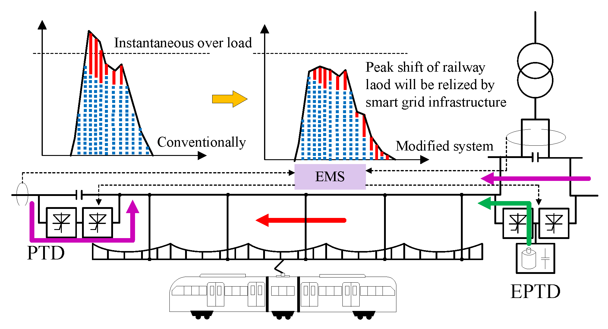
3.3. Peak Cutting and Valley Filling Control

Due to the influence of train running intervals and train carrying capacities, there is peak power in the traction substation. The traction transformer will experience huge power at peak positions, when power surges to traction transformer. In addition, the operation cost and the investment cost are large if the traction transformers are designed according the peak power in convention [22,28,33,35,36]. The effect of peak power surges can be reduced by the modified system. EPTD and PTD can control power flow on both sides connected to it and EPTD can also store up energy as well as release energy, realizing the peak shift control.
Figure 7 shows an example of a peak load waveform caused by the coincidence of some train loads. In a certain power supply section, peak shaving can be realized by releasing the energy stored in EPTD and transferring the power from other adjacent power supply intervals [35,36]. In addition, the cost of the whole railway will be reduced via peak-shift control adopting the smart electrical infrastructure in [33]. The modified system in this paper will further enhance the flexibility of peak-shift control, and the cost of the whole railway will be reduced even more. It should be pointed out that the storage energy in EES will come from regenerative braking energy (see Figure 2) on the one hand and charging power from grid (see Figure 5) on the other hand. By realizing the function of peak shaving, the economic cost of the whole railway will be reduced.
Similarly, there is valley power in the traction substation and valley filling control also needs to be considered. Above all, the filling valley can increase the utilization rate of traction transformers [35,36]. Moreover, valley filling can help balance the supply and demand in an electrical system and reduce cost of electrical railway system. According to market price fluctuations in the electricity market, buying energy at low prices during valley power duration by storing it in ESSs, and when the price is higher, using it to power. In this way, the cost can be reduced even without reducing the total energy consumption [31].

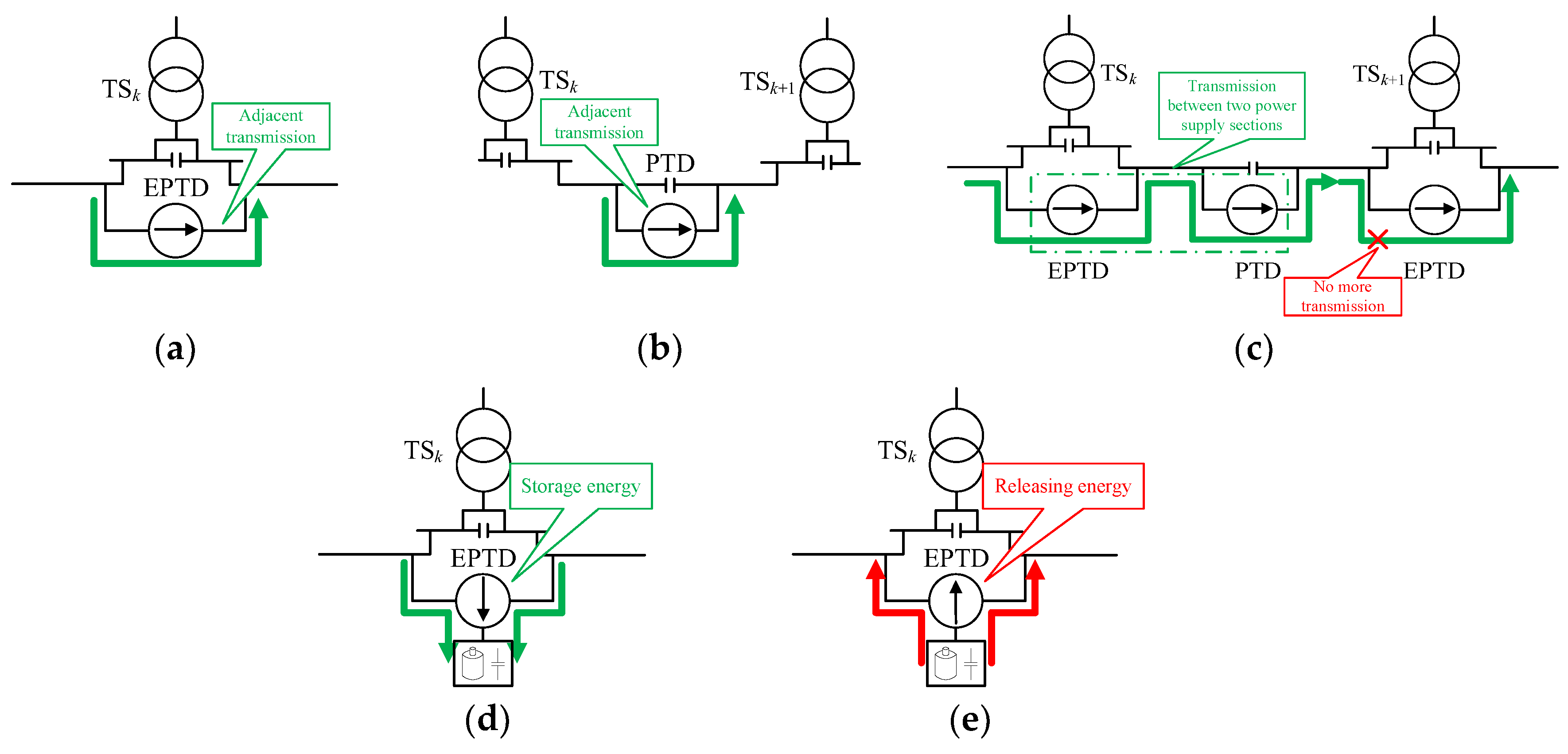
3.4. Management and Control for Clean Energy

Renewable sources such as PV panels and wind generators may be installed to feed railway loads, and this will become a trend in the future [45]. The aim of the measure is to partially power railway loads with clean energy and thus reduce CO2 emissions. Covering part of the energy needs of a railway system through local renewable sources may significantly reduce the amount of energy imported and reduce the ratio of emitted per kWh consumption. However, there are two main problems after introducing renewable sources:
(1) Locational mismatch:
There are distributed usable spaces along railroad tracks for renewable sources in some supply sections of railway systems. In some cases, the traction power in the corresponding electrical section is less than the clean energy, but other electrical sections without renewable sources require power. That means that in some cases the consumption location is away from the generation area, causing locational mismatch (see the location of the regeneration sources in Figure 2).
(2) Temporal mismatch:
In many stations, huge amounts of electric power are consumed during rush hours. However, the hours of PV generation are fixed, i.e., PV generation is active in the daytime and inactive at night. When generating more, the power consumption may not be high. Wind generators experience a similar effect. Therefore, there are temporal mismatches between railway consumption and renewable generation [22].
The modified system can eliminate the locational and temporal mismatches by controlling EPTDs and PTDs so that they can transfer the clean energy to other sections and store as well as release the clean energy to increase the buffer time. By this approach, clean energy can be reasonably controlled through EMS improving the utilization of clean energy, as shown in Figure 2.

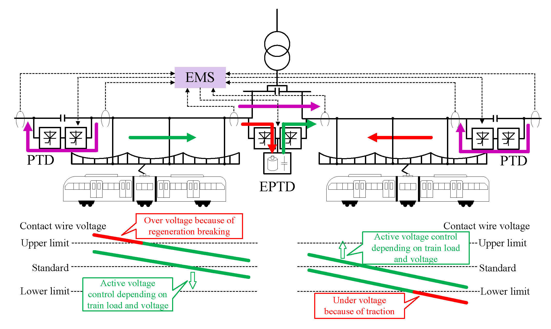
3.5. Active Control for Line Voltage

Traction and regenerative braking of locomotives will cause voltage fluctuations on lines, and the introduction of regenerative sources will also cause voltage fluctuations on lines [20,28]. The effects of the equivalent parameters of the line, such as the reactive power generated by parasitic capacitor, can also cause line voltage fluctuations [46,47]. The range of voltage fluctuation can be suppressed by introducing the modified system. Figure 8 shows the concept of line voltage fluctuation at line ends and the concept of voltage control by use of the modified system. When a locomotive brakes, the regenerative braking power may cause over-voltage in the contact line. The EMS can carry out active voltage control by transferring power via PTD and EPTD and storing the regenerative power in ESS. Similarly, when a locomotive accelerates, the regenerative braking power may cause under-voltage in the contact line. The voltage in the contact line can be kept at a normal via active voltage control. In addition, the modified system can also compensate reactive power to control voltage via PTD and EPTD.

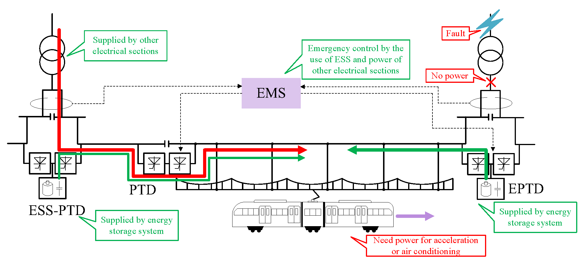
3.6. Emergency Power Supply

In electrified railways, power failures will have important impacts on the operation and the service quality of railways. During blackout conditions, trains will stop running; there will be no ventilation and mugginess in trains, which greatly reduces the comfort of passengers. The modified system will alleviate this problem. In blackout conditions, the EMS can carry out emergency control by the use of ESS and power of other electrical sections, as shown in Figure 9. The emergency control can maintain a train’s operation during blackout conditions at least until it reaches the nearest station. This will avoid long stops between stations on the canal [20], and keep air-conditioning in operation during the remainder of the train journey to ensure the quality of service provided to passengers.

4. Control Algorithm for Utilization of RBE

This paper focused on the realization of eco-friendliness, energy saving, and low carbon of a railway. In order to achieve this goal, a control algorithm for the utilization of RBE based on the modified system was proposed in this paper.

4.1. Algorithm Principles

In the control process for the utilization of RBE in the whole railway line using the modified system, the loss of the RBE in the lines and the power converters is unavoidable. The line loss of the RBE in the flow process is small, accounting for approximately 0.2% [48]. Therefore, the line loss was ignored and the efficiency of the converters alone was considered in this paper. In addition, the capacity of the ESSs was considered to be unlimited.
To utilize the RBE using the modified system, a control algorithm was designed in this paper. The control algorithm principles is as follows:
(1)
Adjacent transmission by EPTD and PTD (see Figure 10a,b).
(2)
Transmission between two power supply sections (see Figure 10c).
(3)
Storage the surplus RBE in ESS (see Figure 10d).
(4)
Release the energy in ESS (see Figure 10e).
The efficiency of the converter is the most important factor affecting the transmission loss of regenerative braking power. The typical topology of an EPTD is shown in Figure 11, and a PTD was similar, including only AC−DC, and DC−AC. In Figure 11, there were two efficiency paths. Path 1 was transferring the regenerative power by the use of AC−DC, DC−AC converter, and its transmission efficiency was η(AC–DC)·η(DC–AC). Path 2 was storing or releasing regenerative power by the use of AC−DC, DC−DC converter, and its transmission efficiency was η(AC–DC)·η(DC–DC). At present, the efficiency of power electronic converters was very high, above 90%, so the efficiencies of η(AC−DC), η(DC−AC), η(DC−DC) were considered to be similar in this paper.
The regenerative power is charged to the ESS during train braking and will be utilized for the powering of systems later. Therefore, the transmission efficiency of RBE via ESS is:
η ES = η ( AC DC ) η ( DC DC ) η ( DC DC ) η ( AC DC ) .
When the surplus regenerative power is transferred to other power sections, the transmission efficiency of RBE via PTD and EPTD is:
η T = ( η ( AC DC ) η ( DC AC ) ) m ,
where m is the number of power supply sections during the process of regenerative power transmission.
When taking m = 1, it can be seen by contrasting (10) and (11) that the transmission efficiency, when transferring regenerative power to the adjacent section via PTD or EPTD, is obviously higher than when it is storing and releasing regenerative power via ESS. Therefore, the most efficient way is to transfer regenerative braking power to the adjacent power supply sections. After principle (1), if there is regenerative power surplus in the whole railway system, this part power will be transferred to other non-adjacent power sections or stored in the ESS. When taking m = 2, the transmission efficiency of transferring regenerative power between two sections via PTD and EPTD is similar to storing and releasing regenerative power via ESS. In order to reduce the capacity and cost of ESS, it allows the transfer of the regenerative power between two power sections via PTD and EPTD. After principle (2), if there is still regenerative power surplus, the surplus power continues to be transferred to other non-adjacent power sections or stored in the ESS. When taking m = 3, the transmission efficiency transferring regenerative power between the three sections via PTDs and EPTDs is lower than storing and releasing regenerative power via ESS. Therefore it is not economical to transfer the regenerative power between three sections, as shown in Figure 10c. Instead, all surplus regenerative power is stored in ESS. Obviously, the RBE utilization efficiency via the modified system in this paper was higher than that via the system in [33]. After principles (1), (2), and (3), if there is traction power needed in some power sections, the previously stored regenerative power will be released to supply the traction power.

4.2. Algorithm Steps

In accordance with the control algorithm principle, the algorithm steps and computational process were designed.
According to the Figure 4, the feeder power satisfied:
P k = i k u k .
Assuming that transferring regenerative power by EPTD and PTD is PPTD,k; the exchange power in ESS is PES,k. A simplified diagram of power flow in the whole railway system for RBE utilization can be obtained, as shown in Figure 12. The green arrow and the red arrow are the positive direction of transmission power and energy storage power respectively, and the power is negative when they are pointing in the opposite direction. Therefore, transferring power to the right is positive and to left is negative; storing power in an ESS is positive and releasing power from an ESS is negative. Defining the transmission efficiency of each converter is ηk = η(AC–DC)·η(DC–AC); the storage and release efficiency of an ESS from its left port is ηLk = η(AC–DC)·η(DC–DC) (arrow 3 and 5 in Figure 11); and the storage or release efficiency of an ESS from its right port is ηRk = η(DC–AC)·η(DC–DC) (arrow 4 and 6 in Figure 11). Before the modified system operates, each feeder power is equal to the train power in the corresponding power supply sections.
(1) Step 1: According to the power data of P1, P2, …, P2n, screening out the power supply sections where the RBE is located and storing the number of the power supply sections in variable j. Firstly, the regenerative power is transmitted to the adjacent power supply sections, as shown in Figure 13.
Case 1: Pj−1 ≤ 0, Pj+1 ≤ 0.
No transmission.
Case 2: Pj−1 > 0, Pj+1 ≤ 0.
The regenerative power in the j power supply section is transferred to the j − 1 power supply section. The RBE should be maximized transmission. Therefore, the transmission power PPTD_1,j−1 in step 1 can be calculated by:
P PTD _ 1 , j 1 = min { | P j 1 / η j 1 | , | P j | } .
It should be noted that when taking j = 2n, the regenerative power in the 2nth power supply section is transferred to the (2n − 1)th power supply section only.
Case 3: Pj−1 ≤ 0, Pj+1 > 0.
The transmission power PPTD_1,j in step 1 can be calculated by:
P PTD _ 1 , j = min { | P j + 1 / η j | , | P j | } .
It should be noted that when taking j = 1, the regenerative power in the 1st power supply section is transferred to the 2nd power supply section only.
Case 4: Pj−1 > 0, Pj+1 > 0.
(i) if |Pj| ≥ |Pj−1/ηj−1| + |Pj+1/ηj|.
The regenerative power in the j power supply section is transferred to the j − 1 power supply section and the j + 1 power supply section. The regenerative power in the j power supply section can supply all traction power required by the j − 1 and j+1 power supply sections. The transmission power in step 1 can be calculated by:
{ P PTD _ 1 , j 1 = | P j 1 / η j 1 | P PTD _ 1 , j = | P j + 1 / η j | .
(ii) if |Pj| < |Pj−1/ηj−1| + |Pj+1/ηj|.
Transmission in accordance with converter efficiency to achieve efficient use of RBE.
When ηj−1 > ηj:
{ P PTD _ 1 , j 1 = min { | P j 1 / η j 1 | , | P j | } P PTD _ 1 , j = ( | P j | | P PTD _ 1 , j 1 | ) .
When ηj−1ηj:
{ P PTD _ 1 , j 1 = ( | P j | | P PTD _ 1 , j | ) P PTD _ 1 , j = min { | P j + 1 / η j | , | P j | } .
(2) Step 2: After step 1, recalculating the feeder power P1, P2, …, P2n. Then, screening out the power supply sections where the RBE is located and storing the number of the power supply sections in variable j again. After adjacent transmission, the power supply section adjacent to the section with regenerative power has no traction power. Therefore, the regenerative power needs to be transmitted between two power supply sections, as shown Figure 14.
Case 1: Pj−2 ≤ 0, Pj+2 ≤ 0.
No transmission.
Case 2: Pj−2 > 0, Pj+2 ≤ 0.
The regenerative power in the j power supply section is transferred to the j − 2 power supply section. However, the transmission process requires two converters to complete. The transmission power PPTD_2,j−1 and PPTD_2,j−2 in step 2 both need both to be calculated by:
{ P PTD _ 2 , j 1 = min { | P j 2 / ( η j 2 η j 1 ) | , | P j | } P PTD _ 2 , j 2 = P PTD , j 1 η j 1 .
It should be noted that when taking j = 2n or j = 2n − 1, the regenerative power in the 2nth or (2n − 1)th power supply section is transferred to the (2n − 2)th or (2n − 3)th power supply section only.
Case 3: Pj-2 ≤ 0, Pj+2 > 0.
The transmission power PPTD_2,j and PPTD_2,j+1 in step 2 both need to be calculated by:
{ P PTD _ 2 , j = min { | P j + 2 / ( η j η j + 1 ) | , | P j | } P PTD _ 2 , j + 1 = P PTD , j η j .
It should be noted that when taking j = 1 or j = 2, the regenerative power in the 1st or 2nd power supply section is transferred to the 3rd or 4th power supply section only.
Case 4: Pj−2 > 0, Pj+2 > 0.
(i) if |Pj| ≥ |Pj-2/(ηj−1·ηj-2)| + |Pj+2/(ηj·ηj+1)|.
The regenerative power in the j power supply section is transferred to the j − 2 power supply section and the j + 2 power supply section. The regenerative power in the j power supply section can supply all traction power required by the j − 2 and j + 2 power supply sections. The transmission power in step 2 can be calculated by:
{ P PTD _ 2 , j 1 = | P j 2 / ( η j 1 η j 2 ) | P PTD _ 2 , j 2 = P PTD _ 2 , j 1 η j 1 P PTD _ 2 , j = | P j + 2 / ( η j η j + 1 ) | P PTD _ 2 , j + 1 = P PTD _ 2 , j η j .
(ii) if |Pj| < |Pj−2/(ηj−1·ηj−2)| + |Pj+2/(ηj·ηj+1)|.
Transmission according to converter efficiency.
When ηj−1·ηj−2 > ηj·ηj+1:
{ P PTD _ 2 , j 1 = min { | P j 1 / ( η j 1 η j 2 ) | , | P j | } P PTD _ 2 , j 2 = P PTD _ 2 , j 1 η j 1 P PTD _ 2 , j = ( | P j | | P PTD _ 2 , j 1 | ) P PTD _ 2 , j + 1 = P PTD _ 2 , j η j .
When ηj−1·ηj−2ηj·ηj+1:
{ P PTD _ 2 , j 1 = ( | P j | | P PTD _ 2 , j | ) P PTD _ 2 , j 2 = P PTD _ 2 , j 1 η j 1 P PTD _ 2 , j = min { | P j + 1 / ( η j η j + 1 ) | , | P j | } P PTD _ 2 , j + 1 = P PTD _ 2 , j η j .
(3) Step 3: After step 2, Recalculating the feeder power P1, P2, …, P2n. Then, screening out the power supply sections where the RBE is located and storing the number of the power supply sections in variable j again. After step 2, if the regenerative power is still surplus, the surplus regenerative power will be stored in ESS.
(i) if j is an odd number.
The regenerative energy power will be stored in ESS by arrow 3 in Figure 11. The storage energy power PES_3,j in step 3 can be calculated by:
P ES _ 3 , j = | P j η L j | .
(ii) if j is an even number.
The storage energy power will be stored in ESS by arrow 4 in Figure 11. The storage energy power in step 3 can be calculated by:
P ES _ 3 , j 1 = | P j η R j 1 | .
After storage, all regenerative power is utilized in railway system.
(4) Step 4: Screening out the ESS with storage energy and storing the number of the ESSs in variable j. j is an odd number (see Figure 3).
Case 1: Pj = 0, Pj+1 = 0.
No release energy.
Case 2: Pj > 0, Pj+1 = 0.
The regenerative power in the j ESS is transferred to the j power supply section by the path 5 in Figure 11. The release energy power PES_4,j in step 4 can be calculated by:
P ES _ 4 , j = min { | P j / η L j | , | P ES j | } .
Case 3: Pj = 0, Pj+1 > 0.
The regenerative power in the j ESS is transferred to the j power supply section by the path 6 in Figure 11. The release energy power in step 4 can be calculated by:
P ES _ 4 , j = min { | P j + 1 / η R j | , | P ES j | } .
Case 4: Pj > 0, Pj+1 > 0.
(i) if |PESj| ≥ |Pj/ηLj| + |Pj+1/ηRj|.
The regenerative power in the j ESS is transferred to the j power supply section and the j + 1 power supply section. The release energy power in step 4 can be calculated by:
P ES _ 4 , j = ( | P j / η L j | + | P j + 1 / η R j | ) .
(ii) if |PESj| < |Pj/ηLj| + |Pj+1/ηRj|.
When ηLj > ηRj, the storage energy in ESSj first releases along arrow 5 in Figure 11, achieving efficient utilization. When ηLjηRj, the storage energy in ESSj first releases along arrow 6 in Figure 11, achieving efficient utilization. However, it should be noted that all storage energy in ESSj is fully utilized in above two cases, and the release energy power can be calculated by:
P ES _ 4 , j = | P ES j | .
Through step 4, the regenerative power stored in the energy storage system is utilized.
Finally, the transmission power references of EPTDs and PTDs and the storage as well as release power references can be calculated by the use of PPTD_1, PPTD_2, PES_3, and PES_4. These references are calculated by the EMS and the relevant data is delivered to the PTDs and EPTDs via bidirectional communication equipment.
In summary, all regenerative power was used within the internal railway system more efficiently by the modified smart system proposed in this paper.

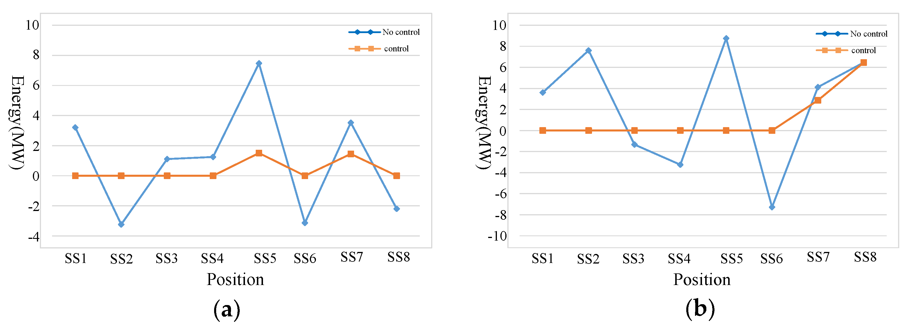
5. Results Verification and Analysis

To evaluate the effectiveness of the modified system and the proposed control algorithm, a modified power supply system consisting of four TSs and eight power supply sections was considered. The diagram of the traction power supply system is shown in Figure 15. The variable data of EPTDs and PTDs and 100 groups of locomotive power data in eight supply power sections were randomly generated in Matlab. The efficiency of AC−DC, DC−AC, and DC−DC converters in EPTDs and PTDs is shown in Table 1. The efficiency ηj, ηLj, and ηRj could be calculated by the use of the data in Table 1. The control algorithm was realized in Matlab.

5.1. Feasibility Evaluation of the Modified System

Based on the aforementioned data, 100 groups of train power consumption of no control results in the original system and control results in the modified system were obtained, as shown in Figure 16. With the proposed system and the control algorithm, the regenerative power was effectively utilized within the internal railway system and the power consumption of the whole railway system was significantly reduced. Moreover, when there are surplus regenerative power in the railway system, the surplus power is stored in ESSs and will be utilized for the powering in the other groups later. The storage energy results in all the ESSs are shown in Figure 17. It can be seen from Figure 17 that the ESSs were not only charged but also discharged, realizing full utilization of all the regenerative power within the internal railway system.
In addition, six groups of the locomotive power data in eight supply power sections of no control results in the original system and control results in the modified system were compared. The comparison results are presented in Figure 18. The power in the corresponding six groups of ESSs is presented in Figure 19. It can be seen from the results that the power consumption in most of supply power sections was reduced to zero after utilizing the regenerative power in trains and the energy in ESSs via modified system, realizing the eco-friendliness and low carbon of railway transportation. Specially, In Figure 18f, the power consumption in all the supply power sections was reduced to zero, realizing the zero-emission of railway transportation. Furthermore, the ESS in EPTD7 had no storage power because the regenerative power in 7th and 8th sections was not surplus after regulating by the control algorithm.

5.2. Advantage Evaluation of the Modified System

Furthermore, a comparison between the energy storage power of the proposed modified system and that of the system with ESSs alone (Figure 1d) was made in Matlab to verify the advantage of the proposed modified system, as shown in Figure 20. It can be seen that the capacity of the energy storage system adopting the proposed system was greatly reduced. When the system with ESSs alone was also adopted, the regenerative power could be utilized through four converter links AC−DC/DC−DC/DC−DC/DC−AC. Compared with the system with ESSs alone, the modified system only needs to pass through two converter links AC−DC/DC−AC to utilize regenerative power when adjacent transmission, which enhances the utilization rate of the regenerative braking energy. In addition, compared with the scheme in [33], the proposed system can utilize all the regenerative power and avoid regenerative power waste. For example, In Figure 18c, the total regenerative power was 30.347 MW, and the total traction power was 26.973 MW. The regenerative power was more than the traction power. If the scheme in [33] is adopted to utilize regenerative power, it will cause regenerative power waste. Instead, the proposed system will solve this problem. Moreover, the proposed system could also enhance the utilization rate of regenerative power compared with the scheme in [33], as analyzed in Section 4.2, avoiding regenerative power transmission between three sections.
However, the cost of energy-storage-based smart electrical infrastructure needs to be considered. The cost of batteries is four times that of converters [49], but there may be discrepancies in practice. If only from the perspective of regenerative braking energy utilization, the economy of the proposed system compared with the system with ESSs alone needs to be discussed, because some literatures consider that the systems with ESSs alone are more economical [20,22]. However, considering that the system has other functions, it will bring more benefits at the same cost. From this point of view, the proposed system will be more competitive economically. In addition, with the development of the technology and the increased demand of batteries, the cost of the batteries will be gradually reduced, thereby greatly improving the application potential of the proposed system. Moreover, in some railways with large slopes, more regenerative braking energy will be generated [17]. In these railways, the economic benefits of the proposed system will be more obvious. The scheme of adding ESS in AC-fed railway system has also received attention and been studied [34,35,36,50], which proves the feasibility of the application of the proposed system based on the energy storage scheme in the railway system. Last but not least, the capacity of the ESSs in the proposed system can be optimized, thereby reducing the cost of the ESSs. Then, the regenerative braking energy can be effectively utilized while ensuring the minimum capacity and cost of the ESSs, thereby further improving the economics of the proposed modified system. It also should be noted that this paper did not consider the issue of the capacity constraints of the ESSs. However in the future research work, the author will further optimize the capacity of the ESSs and design the control strategy under the capacity constraints of the ESSs, thereby enhancing the economic advantage of the proposed system.
In addition, it should be noted that the data was randomly obtained by Matlab, and whether the result of zero-emission of railway transportation in Figure 18f will be achieved in practice still needs to be discussed. This mainly depends on the regenerative braking energy produced by locomotives in actual. However, if clean energy is added for powering traction in the railway system in the future, combined with the energy-storage-based smart electrical infrastructure proposed in this paper, the zero-emission of railway transportation could be realized in the future.
The feasibility of the additional functions of power quality improvement, peak cutting and valley filling, management and control for clean energy, active control for line voltage, and emergency power supply are widely discussed in literatures [5,6,14,20,21,22,23,24,28,30,31,32,35,36,37,38,39,40,41,42,43,44]. For the realization process and verification results of those functions, readers can see the above-mentioned literatures. This paper would no longer validate those functions. The energy-storage-based smart electrical system proposed in this paper could integrate these functions instead of allowing them to operation independently, providing options for smart and eco-friendliness of railway in the future.
This paper focused on regenerative braking energy utilization via the proposed system, realizing eco-friendly railway transportation system. In the future, the author will further investigate the other functions of the proposed system, so as to maximize the benefits of the proposed system.

6. Conclusions

This paper presented a modified system to improve the current AC-fed railway power supply systems, which could enhance the eco-friendliness and smart level of railway. The modified system further improved the degree of controllability of the infrastructure, which allowed for many functions as follows:
  • Utilization of regenerative braking energy;
  • Power quality improvement;
  • Peak cutting and valley filling;
  • Management and control for clean energy;
  • Active control for line voltage;
  • Emergency power supply.
In addition, to utilize the regenerative braking energy, a control algorithm based on the modified system was proposed to realize efficient utilization of all the regenerative power within the internal railway system, making traction consumption of railway systems reduction greatly and more eco-friendliness.
Finally, the advantages of the proposed system and the effectiveness of the proposed control algorithm were verified in a case of a modified power supply system consisting of four traction substations and eight power supply sections. The results showed that the regenerative braking energy in railway could be efficiently utilized by using the improved system and the control algorithm. The work conducted in this paper would provide alternative methods for railway smart control and energy saving and consumption reduction.

Author Contributions

Z.G. and Q.L. designed the research; J.F. and C.W. gave help of validation and formula derivation; Z.G. and B.H. finished the verification; Z.G. wrote the paper.

Funding

This research was funded in part by [the Shenhua Group Co., Ltd., Science and Technology Innovation Projects] grant number [CSIE16024877], and in part by [the National Natural Science Foundation of China] grant number [51577187].

Conflicts of Interest

The authors declare no conflict of interest.

References

  1. Douglas, H.; Roberts, C.; Hillmansen, S.; Schmid, F. An assessment of available measures to reduce traction energy use in railway networks. Energy Conv. Manag. 2015, 106, 1149–1165. [Google Scholar] [CrossRef]
  2. The International Energy Agency (IEA) and the International Union of Railways (UIC). Railway Handbook: Energy Consumption and CO2 Emissions. Available online: https://www.iea.org/topics/transport/railwayhandbook (accessed on 3 October 2019).
  3. Bukarica, V.; Tomsic, Z. Design and evaluation of policy instruments for energy efficiency market. IEEE Trans. Sustain. Energy 2017, 8, 354–362. [Google Scholar] [CrossRef]
  4. Pankovits, P.; Pouget, J.; Robyns, B.; Delhaye, F.; Brisset, S. Towards railway-smartgrid: Energy management optimization for hybrid railway power substations. In Proceedings of the 5th IEEE PES Innovative Smart Grid Technologies Conference Europe (ISGT Europe), Istanbul, Turkey, 12–15 October 2014. [Google Scholar]
  5. Hernandez, J.C.; Sutil, F.S. Electric vehicle charging stations feeded by renewable: PV and train regenerative braking. IEEE Latin Am. Trans. 2016, 14, 3262–3269. [Google Scholar] [CrossRef]
  6. Aguado, J.A.; Racero, A.J.S.; De La Torre, S. Optimal operation of electric railways with renewable energy and electric storage systems. IEEE Trans. Smart Grid. 2018, 9, 993–1001. [Google Scholar] [CrossRef]
  7. Hayashiya, H.; Itagaki, H.; Morita, Y.; Mitoma, Y.; Furukawa, T.; Kuraoka, T.; Fukasawa, Y.; Oikawa, T. Potentials, peculiarities and prospects of solar power generation on the railway premises. In Proceedings of the 2012 International Conference on Renewable Energy Research and Applications (ICRERA), Nagasaki, Japan, 11–14 November 2012. [Google Scholar]
  8. Bocharnikov, Y.V.; Tobias, A.M.; Roberts, C.; Hillmansen, S.; Goodman, C.J. Optimal driving strategy for traction energy saving on DC suburban railways. IET Electr. Power Appl. 2007, 5, 675–682. [Google Scholar] [CrossRef]
  9. Li, L.; Dong, W.; Ji, Y.D.; Zhang, Z.K.; Tong, L. Minimal-energy driving strategy for high-speed electric train with hybrid system model. IEEE Trans. Intell. Transp. Syst. 2013, 14, 1642–1653. [Google Scholar] [CrossRef]
  10. Johnson, P.; Brown, S. A simple in-cab schedule advisory system to save energy and improve on-time performance. In Proceedings of the IET Conference on Railway Traction Systems (RTS 2010), Birmingham, UK, 13–15 April 2010. [Google Scholar]
  11. Li, Y.; Tomas, L.; Per, L. Achieving energy-efficiency and on-time performance with Driver Advisory Systems. In Proceedings of the 2013 IEEE International Conference on Intelligent Rail Transportation Proceedings, Beijing, China, 30 August–1 September 2013. [Google Scholar]
  12. Wang, Y.; Hou, Z.S.; Li, X.Y. A novel automatic train operation algorithm based on iterative learning control theory. In Proceedings of the 2008 IEEE International Conference on Service Operations and Logistics, and Informatics, Beijing, China, 12–15 October 2008. [Google Scholar]
  13. Li, Z.X.; Yin, C.K.; Jin, S.T.; Hou, Z.S. Iterative learning control based automatic train operation with iteration-varying parameter. In Proceedings of the 2013 10th IEEE International Conference on Control and Automation (ICCA), Hangzhou, China, 12–14 June 2013. [Google Scholar]
  14. Hayashiya, H.; Yokokawa, S.; Iino, Y.; Kikuchi, S.; Suzuki, T.; Uematsu, S.; Sato, N.; Usui, T. Regenerative energy utilization in a.c. traction power supply system. In Proceedings of the 2016 IEEE International Power Electronics and Motion Control Conference (PEMC), Varna, Bulgaria, 25–28 September 2016. [Google Scholar]
  15. Hayashiya, H.; Kikuchi, S.; Matsuura, K.; Hino, M.; Tojo, M.; Kato, T.; Ando, M.; Oikawa, T.; Kamata, M.; Munakata, H. Possibility of energy saving by introducing energy conversion and energy storage technologies in traction power supply system. In Proceedings of the 2013 15th European Conference on Power Electronics and Applications (EPE), Lille, France, 2–6 September 2013. [Google Scholar]
  16. Hayashiya, H.; Nakao, Y.; Aoki, Y.; Kobayashi, S.; Ogihara, M. Comparison between energy storage system and regenerative inverter in D.C. traction power supply system for regenerative energy utilization. In Proceedings of the 2017 19th European Conference on Power Electronics and Applications (EPE’17 ECCE Europe), Warsaw, Poland, 11–14 September 2017. [Google Scholar]
  17. Lu, Q.W.; He, B.B.; Wu, M.Z.; Zhang, Z.C.; Luo, J.T.; Zhang, Y.K.; He, R.K.; Wang, K.Y. Establishment and analysis of energy consumption model of heavy-haul train on large long slope. Energies 2018, 11, 965. [Google Scholar] [CrossRef]
  18. Yang, X.; Li, X.; Gao, Z.Y.; Wang, H.W.; Tang, T. A cooperative scheduling model for timetable optimization in subway systems. IEEE Trans. Intell. Transp. Syst. 2013, 14, 438–447. [Google Scholar] [CrossRef]
  19. González-Gil, A.; Palacin, R.; Batty, P. Sustainable urban rail systems: Strategies and technologies for optimal management of regenerative braking energy. Energy Convers. Manag. 2013, 75, 374–388. [Google Scholar] [CrossRef]
  20. Hayashiya, H.; Iino, Y.; Takahashi, H.; Kawahara, K.; Yamanoi, T.; Sekiguchi, T.; Sakaguchi, H.; Sumiya, A.; Kon, S. Review of regenerative energy utilization in traction power supply system in Japan: Applications of energy storage systems in d.c. traction power supply system. In Proceedings of the IECON 2017–43rd Annual Conference of the IEEE Industrial Electronics Society, Beijing, China, 29 October–1 November 2017. [Google Scholar]
  21. Hayashiya, H.; Suzuki, T.; Kawahara, K.; Yamanoi, T. Comparative study of investment and efficiency to reduce energy consumption in traction power supply: A present situation of regenerative energy utilization by energy storage system. In Proceedings of the 2014 16th International Power Electronics and Motion Control Conference and Exposition (PEMC), Antalya, Turkey, 21–24 September 2014. [Google Scholar]
  22. Hayashiya, H.; Watanabe, Y.; Fukasawa, Y.; Miyagawa, T.; Egami, A.; Iwagami, T.; Kikuchi, S.; Yoshizumi, H. Cost impacts of high efficiency power supply technologies in railway power supply–Traction and Station. In Proceedings of the 2012 15th International Power Electronics and Motion Control Conference (EPE/PEMC), Novi Sad, Serbia, 4–6 September 2012. [Google Scholar]
  23. Kaleybar, H.J.; Kojabadi, H.M.; Brenna, M.; Foiadelli, F.; Zaninelli, D. An intelligent strategy for regenerative braking energy harvesting in AC electrical railway substation. In Proceedings of the 2017 5th IEEE International Conference on Models and Technologies for Intelligent Transportation Systems (MT-ITS), Naples, Italy, 26–28 June 2017. [Google Scholar]
  24. Wang, Y.; Chen, M.; Lei, G.; Luo, J. Flexible traction power system adopting energy optimisation controller for AC-fed railway. Electron. Lett. 2017, 53, 554–556. [Google Scholar] [CrossRef]
  25. Pilo De La Fuente, E.; Mazumder, S.K.; Franco, I.G. Railway Electrical Smart Grids: An introduction to next-generation railway power systems and their operation. IEEE Electrif. Mag. 2014, 2, 49–55. [Google Scholar] [CrossRef]
  26. Palfreyman, T.; Hewings, D. The smart grid applied to railway traction systems: A future vision and integrated protection & control. In Proceedings of the 6th IET Professional Development Course on Railway Electrification Infrastructure and Systems (REIS 2013), London, UK, 3–6 June 2013. [Google Scholar]
  27. Bartłomiejczyk, M. Smart grid technologies in electric traction: Mini inverter station. In Proceedings of the 2017 Zooming Innovation in Consumer Electronics International Conference (ZINC), Novi Sad, Serbia, 31 May–1 June 2017. [Google Scholar]
  28. Hayashiya, H.; Yoshizumi, H.; Suzuki, T.; Furukawa, T.; Kondoh, T.; Kitano, M.; Aoki, T.; Ishii, T.; Kurosawa, N.; Miyagawa, T. Necessity and possibility of smart grid technology application on railway power supply system. In Proceedings of the 14th European Conference on Power Electronics and Applications, Birmingham, UK, 30 August–1 September 2011. [Google Scholar]
  29. Nasr, S.; Iordache, M.; Petit, M. Smart micro-grid integration in DC railway systems. In Proceedings of the IEEE PES Innovative Smart Grid Technologies, Europe, Istanbul, Turkey, 12–15 October 2014. [Google Scholar]
  30. Şengör, I.; Kiliçkiran, H.C.; Akdemir, H.; Kekezoǧlu, B.; Erdinç, O.; Catalão, J.P.S. Energy management of a smart railway station considering regenerative braking and stochastic behaviour of ESS and PV generation. IEEE Trans. Sustain. Energy 2018, 9, 1041–1050. [Google Scholar] [CrossRef]
  31. Khayyam, S.; Ponci, F.; Goikoetxea, J.; Recagno, V.; Bagliano, V.; Monti, A. Railway Energy management system: Centralized-decentralized automation architecture. IEEE Trans. Smart Grid. 2016, 7, 1164–1175. [Google Scholar] [CrossRef]
  32. Novak, H.; Vasak, M.; Lesic, M. Hierarchical energy management of multi-train railway transport system with energy storages. In Proceedings of the IEEE International Conference on Intelligent Rail Transportation (ICIRT), Birmingham, UK, 23–25 August 2016. [Google Scholar]
  33. Pilo, E.; Mazumder, S.K.; González-Franco, I. Smart electrical infrastructure for AC-fed railways with neutral zones. IEEE Trans. Intell. Transp. Syst. 2015, 16, 642–652. [Google Scholar] [CrossRef]
  34. Kazunori, T.; Masaaki, T.; Hitoshi, H.; Yumiko, I. Proposal and effect evaluation of RPC application with energy storage system for regenerative energy utilization of high speed railway. J. Int. Counc. Electr. Eng. 2017, 7, 227–232. [Google Scholar] [Green Version]
  35. Ma, Q.; Guo, X.; Luo, P.; Zhang, Z.W. Coordinated control strategy design of new type railway power regulator based on super capacitor energy storage. Trans. Chin. Electr. Soc. 2018, 34, 765–776. (In Chinese) [Google Scholar]
  36. Ma, Q.; Guo, X.; Luo, P.; Zhang, Z.W. A novel railway power conditioner based on super capacitor energy storage system. Trans. Chin. Electr. Soc. 2018, 33, 1208–1218. (In Chinese) [Google Scholar]
  37. Wei, W.J.; Hu, H.T.; Wang, K.; Chen, J.Y.; He, Z.Y. Energy storage scheme and control strategies of high-speed railway based on railway power conditioner. Trans. Chin. Electr. Soc. 2019, 34, 1290–1299. (In Chinese) [Google Scholar]
  38. Deng, W.L.; Dai, C.H.; Han, C.B.X.; Chen, W.R. Back-to-back hybrid energy storage system of electric railway and its control method considering regenerative braking energy recovery and power quality improvement. Proc. CSEE 2019, 39, 2914–2923. (In Chinese) [Google Scholar]
  39. Luo, A.; Wu, C.P.; Shen, J.; Shuai, Z.K.; Ma, F.J. Railway static power conditioners for high-speed train traction power supply systems using three-phase V/V transformers. IEEE Trans. Power Electron. 2011, 26, 2844–2856. [Google Scholar] [CrossRef]
  40. Chen, M.W.; Chen, Y.Y.; Wei, M.C. Modeling and control of a novel hybrid power quality compensation system for 25-kV electrified railway. Energies 2019, 12, 3303. [Google Scholar] [CrossRef]
  41. Roudsari, H.M.; Jalilian, A.; Jamali, S. Flexible fractional compensating mode for railway static power conditioner in a V/v traction power supply system. IEEE Trans. Ind. Electron. 2018, 65, 7963–7974. [Google Scholar] [CrossRef]
  42. Zhang, D.H.; Zhang, Z.X.; Wang, W.; Yang, Y.L. Negative sequence current optimizing control based on railway static power conditioner in V/v traction power supply system. IEEE Trans. Power Electron. 2016, 31, 200–212. [Google Scholar] [CrossRef]
  43. Langerudy, A.T.; Mousavi, G.S.M. Hybrid railway power quality conditioner for high-capacity traction substation with auto-tuned DC-link controller. IET Electr. Syst. Transp. 2016, 6, 207–214. [Google Scholar] [CrossRef]
  44. Zhu, Z.; Ma, F.J.; Wang, X.; Deng, L.F.; Li, G.X.; Wei, X.W.; Tang, Y.X.; Liu, S.Y. Operation analysis and a game theoretic approach to dynamic hybrid compensator for the V/v traction system. IEEE Trans. Power Electron. 2019, 34, 8574–8587. [Google Scholar] [CrossRef]
  45. The International Energy Agency (IEA). The Future of Rail: Opportunities for Energy and the Environment. Available online: https://www.iea.org/futureofrail (accessed on 23 October 2019).
  46. Perin, I.; Walker, G.R.; Ledwich, G. Load sharing and wayside battery storage for improving AC railway network performance, with generic model for capacity estimation, part 1. IEEE Trans. Ind. Electron. 2019, 66, 1791–1798. [Google Scholar] [CrossRef]
  47. Perin, I.; Walker, G.R.; Ledwich, G. Load sharing and wayside battery storage for improving AC railway network performance, with generic model for capacity estimation, part 2. IEEE Trans. Ind. Electron. 2018, 65, 9459–9467. [Google Scholar] [CrossRef]
  48. Ma, F.J.; Luo, A.; Xu, X.Y.; Xiao, H.G.; Wu, C.P.; Wang, W. A simplified power conditioner based on half-bridge converter for high-speed railway system. IEEE Trans. Power Electron. 2013, 60, 728–738. [Google Scholar] [CrossRef]
  49. Gelman, V. Energy storage that may be too good to be true: Comparison between wayside storage and reversible thyristor controlled rectifiers for heavy rail. IEEE Veh. Technol. Mag. 2013, 8, 70–80. [Google Scholar] [CrossRef]
  50. Gui, G.P.; Luo, L.F.; Liang, C.G.; Hu, S.J.; Li, Y.; Cao, Y.J.; Xie, B.; Xu, J.Z.; Zhang, Z.W.; Liu, Y.X.; et al. supercapacitor integrated railway static power conditioner for regenerative braking energy recycling and power quality improvement of high-speed railway system. IEEE Trans. Transp. Electrif. 2019, 5, 702–714. [Google Scholar]
Figure 1. Regenerative braking energy (RBE) utilization schemes (a) regenerative resistance; (b) feeding into grid; (c) feeding into distribution grid; (d) storage energy with an energy storage system (ESS); (e) tie feeding in a section post (SP); (f) tie feeding in a traction substation (TS); and (g) smart electrical infrastructure.
Energies 12 04053 g001
Figure 2. Energy-storage-based smart electrical infrastructure.
Energies 12 04053 g002
Figure 3. The railway traction system with energy-storage-based smart electrical infrastructure.
Energies 12 04053 g003
Figure 4. The simplified system and its electrical description.
Energies 12 04053 g004
Figure 5. Energy distribution of the whole railway system.
Energies 12 04053 g005
Figure 6. Power quality improvement by PTD with the ESS (EPTD).
Energies 12 04053 g006
Figure 7. Peak shaving based on the modified system.
Energies 12 04053 g007
Figure 8. Active voltage control based on the modified system.
Energies 12 04053 g008
Figure 9. Emergency control based on the modified system.
Energies 12 04053 g009
Figure 10. Control algorithm principle: (a) adjacent transmission; (b) adjacent transmission; (c) transmission between two power supply sections; (d) storage energy; and (e) release energy.
Energies 12 04053 g010
Figure 11. Typical topology and operation paths of EPTD.
Energies 12 04053 g011
Figure 12. The simplified electrical description for RBE utilization.
Energies 12 04053 g012
Figure 13. Adjacent transmission.
Energies 12 04053 g013
Figure 14. Transmission between two power supply sections.
Energies 12 04053 g014
Figure 15. The diagram of the modified power supply system.
Energies 12 04053 g015
Figure 16. Results before and after control.
Energies 12 04053 g016
Figure 17. Energy storage results.
Energies 12 04053 g017
Figure 18. Partial comparison results before and after control: (a) 60th group; (b) 61th group; (c) 62th group; (d) 63th group; (e) 64th group; and (f) 65th group.
Energies 12 04053 g018aEnergies 12 04053 g018b
Figure 19. The results in six groups of ESSs.
Energies 12 04053 g019
Figure 20. A comparison results of energy storage power between the proposed modified system and the energy storage system.
Energies 12 04053 g020
Table 1. Converter efficiency.
Typeη(AC−DC)η(DC−AC)η(DC−DC)
EPTD10.96900.97560.9753
PTD20.96090.9665
EPTD30.98610.95010.9736
PTD40.98860.9790-
EPTD50.98470.95860.9721
PTD60.98100.9597-
EPTD70.98810.95750.9786

