Article

Research on Access Mode of the Flexible DC Power Distribution System into AC System

1
School of Electric Power, South China University of Technology, Guangzhou 510640, China
2
Zhuhai Power Supply Bureau, Guangdong Power Grid Co., Ltd., Zhuhai 519000, China
3
State Key Lab of Power Systems (Department of Electrical Engineering), Tsinghua University, Beijing 100084, China
4
DC Research Center, Energy Internet Institute, Tsinghua University, Beijing 100084, China
*
Authors to whom correspondence should be addressed.
Energies 2019, 12(20), 4002; https://doi.org/10.3390/en12204002
Submission received: 11 September 2019 / Revised: 15 October 2019 / Accepted: 18 October 2019 / Published: 21 October 2019
(This article belongs to the Section F: Electrical Engineering)

Abstract

:
The connection mode of the direct current (DC) power distribution system and the alternating current (AC) system is the foundation of system design, and it is also one of key technologies of the DC power distribution network. Based on the topology structure, grounding method, main equipment parameters, load parameters and system control protection strategy of the DC power distribution system, this paper establishes the system simulation model in the case of configuring the connection transformer and not configuring the connection transformer. Simulation results show that, when no connecting transformer is installed, the interaction between AC and DC systems will be great when faults occur, and the cost of converter valves and DC reactors will be increased. When connecting transformers are installed, the interaction between AC and DC systems can be effectively isolated, and the operation reliability of the system will be greatly improved while the cost is saved. Therefore, it is recommended to configure an independent connection transformer in the DC distribution system.

1. Introduction

The direct current (DC) power distribution network has many advantages, it can improve the power quality, decrease the power loss and running cost, harmonize the contradiction between the power grid and distributed power supply effectively [1,2,3,4,5,6,7]. Therefore, it has become one of the important directions of research on the distribution network.
The connection mode of the DC power distribution network and the alternating current (AC) network is the basis of system design and one of the key technologies in the DC power distribution [8,9,10]. System fault simulation is carried out generally in order to study the operating characteristics for a connection between the AC network and the DC network. Experts and scholars have completed a lot of research on DC fault analysis. In reference [11], the fault mechanism of the modular multilevel converter (MMC) DC-side bipolar short circuit is analyzed, and the circuit model of overcurrent analysis is established. In reference [12], the transient characteristics of the MMChigh-voltage direct current (HVDC) DC-side fault are studied, and the equivalent circuit model under short-circuit fault is established. The mathematical expressions of fault voltage and current are given. Based on the mechanism of the MMC DC-side bipolar short circuit fault, references [13,14] establish the fault current analytical expression of each stage of the fault development process. In reference [15], the DC fault characteristics of the MMC-HVDC are analyzed in depth, and the equivalent circuit model of the MMC under fault is proposed. In reference [16], a general calculation method of the fault current is proposed for the DC-side bipolar short-circuit fault of the flexible DC grid. In reference [17], the overvoltage and insulation coordination of a flexible DC power distribution network is studied.
Therefore, this paper uses the method of fault simulation analysis to study the connection mode between the DC distribution system and the AC system. A system simulation model configured with the connecting transformer and not configured with the connection transformer are established separately. Simulation analysis is conducted for the connection mode of the DC power distribution system and the AC network. Then, the AC-side fault simulation analysis and DC-side fault simulation analysis are carried out to study the influence of whether to configure the connection transformer on the system characteristics.

2. System Overview

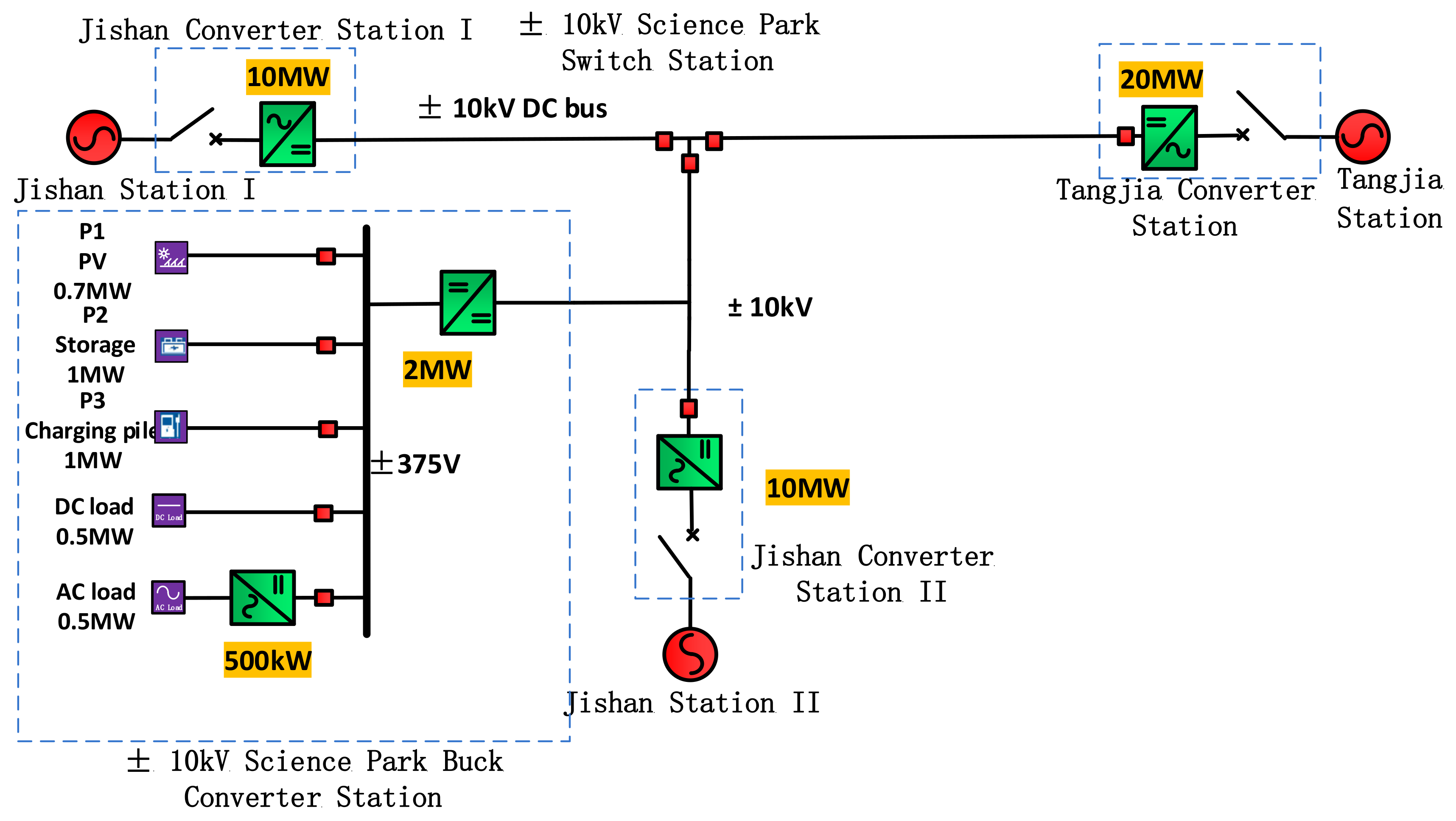
2.1. System Structure

The system structure of a ±10 kV flexible DC distribution system is shown in Figure 1. In order to realize the power transfer function and improve the power supply reliability of the power distribution network, the system is equipped with a “star” network topology with three independent AC power sources. The three-terminal AC system is connected with the medium-voltage DC distribution bus through a fully controlled voltage source converter in order to improve the power quality of the AC power distribution network associated with the DC power distribution system [7].
The relevant parameters of the converter are shown in Table 1.
The type and capacity of source, storage and load in the flexible DC power distribution system are shown in Table 2.

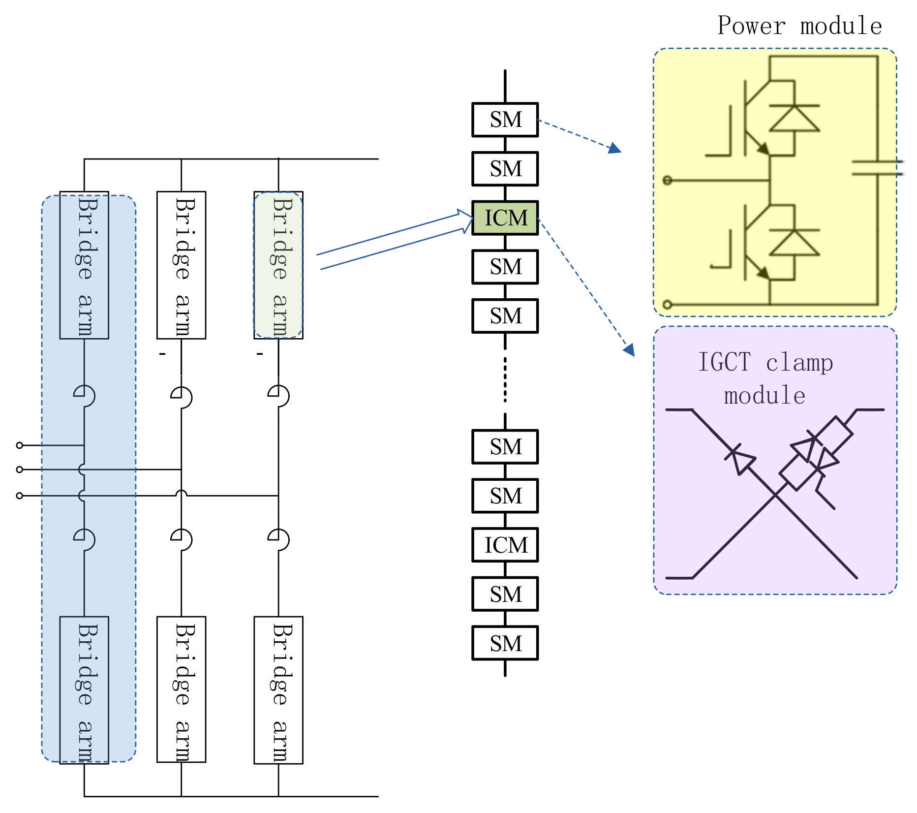
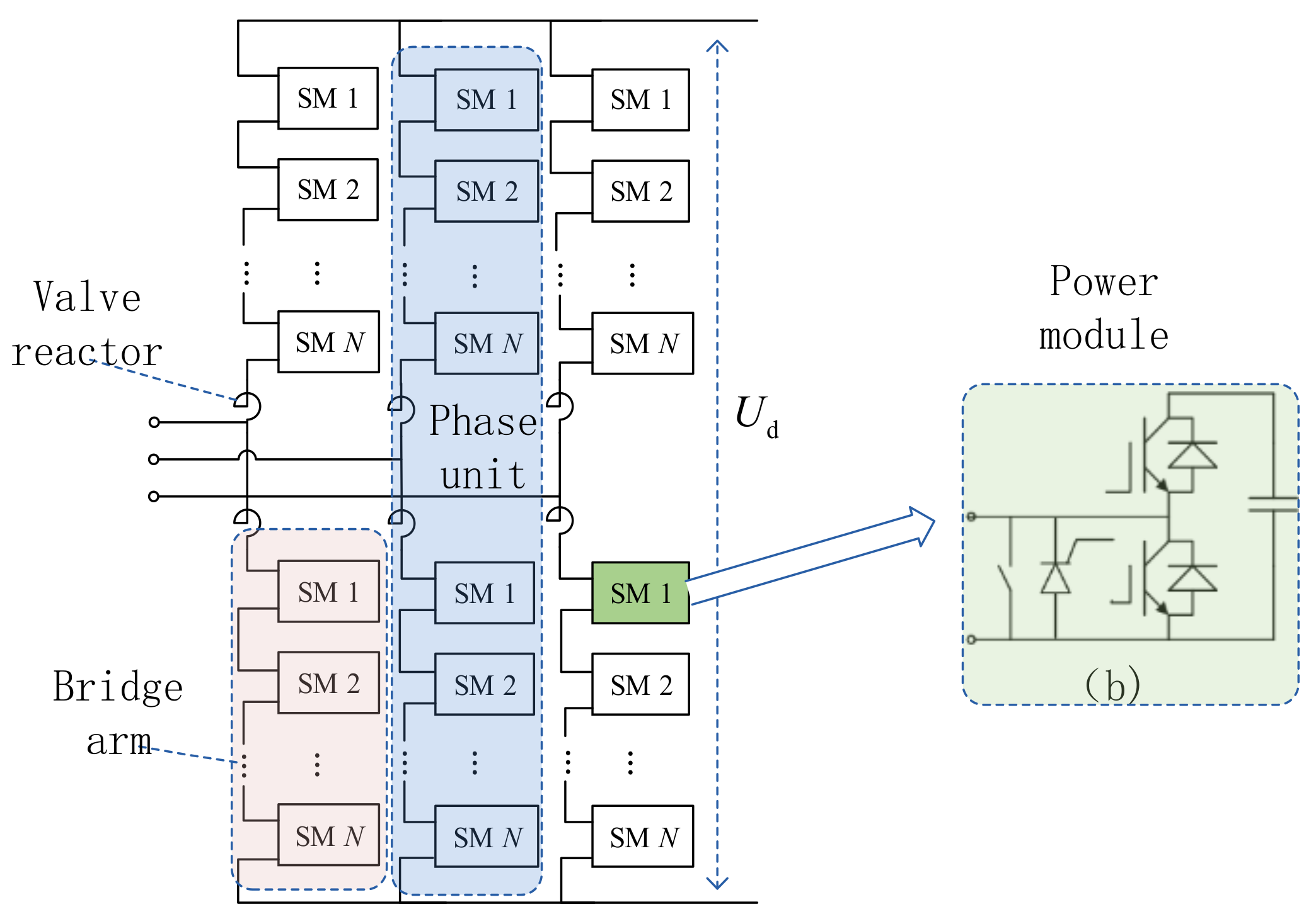
2.2. Modular Multilevel Converter (MMC)

For Tangjia station and Jishan II station, because the DC bus is equipped with a DC circuit breaker, a basic MMC converter topology can be used. The power module topology is shown in Figure 2 [7].
Since the DC bus of Jishan Station 1 is not equipped with a DC breaker, its converter should adopt a topology with a DC fault self-clearing capability. The power module topology is shown in Figure 3 [7].

2.3. Short Circuit Fault Analysis

2.3.1. AC-Side Short Circuit Fault

Taking the single-phase grounding fault as an example to analyze the fault characteristics of the AC side, when a single-phase grounding fault occurs in the A phase of the AC system, it will be given as [8]:
U ˙ AK = 0 U ˙ BK = E ˙ B E ˙ A = 3 E ˙ A e j 5 π / 6 U ˙ CK = E ˙ C E ˙ A = 3 E ˙ A e j 5 π / 6
where, EA, EB, EC are the three relative ground voltages of the AC system, and UAK, UBK, UCK are the three relative ground voltages of the fault point. According to the symmetric component method, the zero-sequence voltage is given as:
U ˙ 0 = 1 3 U ˙ AK + U ˙ BK + U ˙ CK = E ˙ A
When the connection transformer is configured, because the converter transformer adopts triangle connection mode, the zero-sequence current will not be traded, so there is no zero-sequence component in the valve side and the DC side.

2.3.2. DC-Side Short Circuit Fault

After the bipolar short-circuit fault occurs on the DC side of the MMC, the fault current is mainly divided into a sub-module capacitive discharge current and an AC system feed-in current, in which the capacitive discharge current is the main part. The AC current feed-in cannot be considered in analytical calculation [18]. The equivalent circuit of capacitive discharge of the MMC sub-module before blocking is shown in Figure 4.
According to circuit theory, the expression of the fault current can be obtained as follows:
i dc t = e t τ U dc C e L e sin ω t I dc 0 ω 0 ω 1 sin ω 1 t θ 1
where, U dc is the DC bus voltage of the MMC, I dc 0 is the initial current, τ is the decay time constant of the discharge current, θ 1 is the initial phase angle determined by the initial current, ϖ 0 is the resonance angle frequency, ϖ 1 is the angular frequency of the oscillating current, L e = 2 L / 3 , L is the equivalent reactance of the bridge arm, and C e is the equivalent capacitance of the bridge arm.

3. System Configuring with Connection Transformer

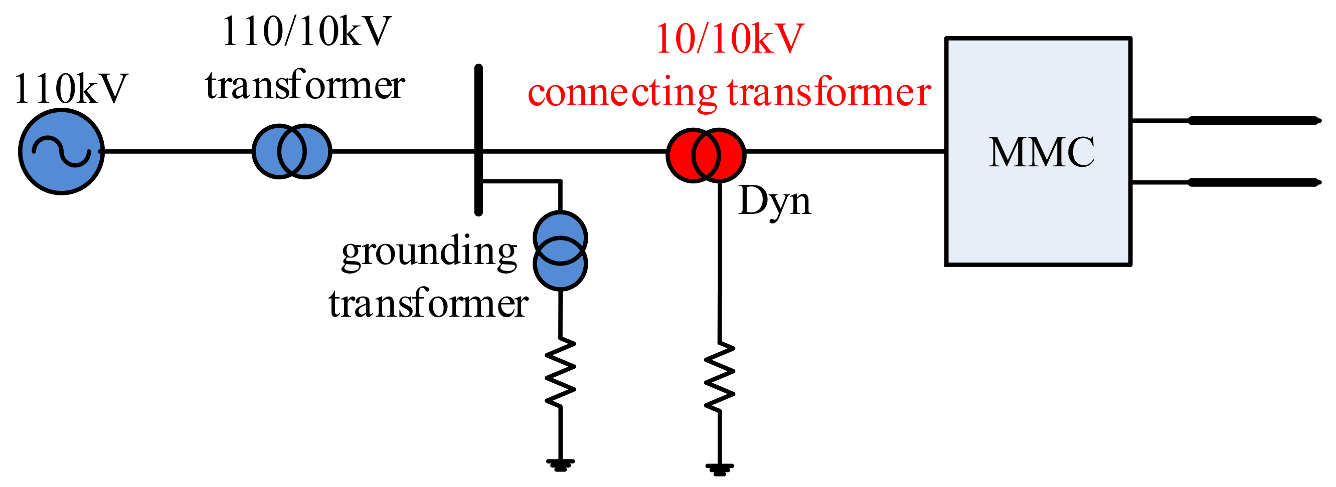
3.1. Access Mode for Connection Transformer

The traditional high-voltage direct current (HVDC) transmission system uses a converter transformer to connect to the AC grid, and the converter transformer and the converter valve together realize power conversion and electrical isolation between the AC system and the DC system. The flexible HVDC systems generally use connection transformers to connect with AC systems. The connection transformers can realize voltage conversion and make voltage source converters work in the optimal voltage range. Referring to the flexible HVDC transmission system, the flexible medium voltage direct current (MVDC) distribution system can be connected to the AC network by the connection transformer [6].
For the ±10 kV DC distribution system shown in Figure 1, the AC side is connected to the 10 kV AC distribution network. The connection transformer adopts a 10 kV/10 kV transformer, and the connection group is Dyn. That’s because the connection transformer is the link of power transmission between the AC side and the DC side. In order to isolate the influence of zero-sequence components at both ends of the transformer, the connection transformer is generally designed to eliminate zero-sequence components, and one side of the transformer must be an ungrounded system. For the connection mode of a single converter, the three-phase double-winding transformer with the Dyn connection is usually used. The neutral point is grounded by resistance, which provides the ground potential reference point for the DC distribution system [7].
According to relevant requirements of the urban distribution network planning and design specification, the limit of the single-phase continuous grounding current of the non-effective earthing system is 10 A. Therefore, the continuous DC grounding current under the single-pole grounding fault of the DC power distribution system is also considered to be limited below 10 A. When the system has a positive ground fault, the neutral point potential jumps to the negative value of the fault pole−10 kV. When the ground current is less than 10 A, the grounding resistance should be greater than 2000 Ω. In the case of a single-pole ground fault, the unbalanced voltage is 10 kV, and the grounding current is 10 A, which allows the three-phase DC current flowing through the connecting transformer to be 5 A, and the grounding resistance should be no less than 2000 Ω. Considering a certain margin, the grounding resistance that satisfies the continuous ground current and the DC bias of the transformer is taken as 3500 Ω.
When configuring the connection transformer, the main circuit connection of the DC power distribution system is shown in Figure 5. In the figure, the converter of the DC power distribution system is connected to the 10 kV AC bus through the 10 kV/10 kV connection transformer, and the 10 kV AC bus is taken out through the 110 kV/10 kV power transformer. There is no neutral point in the 10 kV AC power distribution system. The grounding is realized by connecting the grounding transformer of the Z-connection group on the busbar of the 10 kV AC system. The neutral point of the grounding transformer is grounded by a small resistance.

3.2. System Simulation Analysis

In this section, based on the topological structure and system parameters of the DC distribution system with connection transformer, the system simulation model is established in Power Systems Computer Aided Design/Electromagnetic Transients including DC (PSCAD/EMTDC) to simulate the faults on the AC side and the DC side. According to the simulation results, the influence of AC side faults on DC side voltage and current, and the influence of DC side faults on AC side voltage and current, are analyzed.

3.2.1. Normal Operation

When the system is in normal operation, the overvoltage and overcurrent levels at key positions of the system are shown in Table 3 and Table 4, respectively.

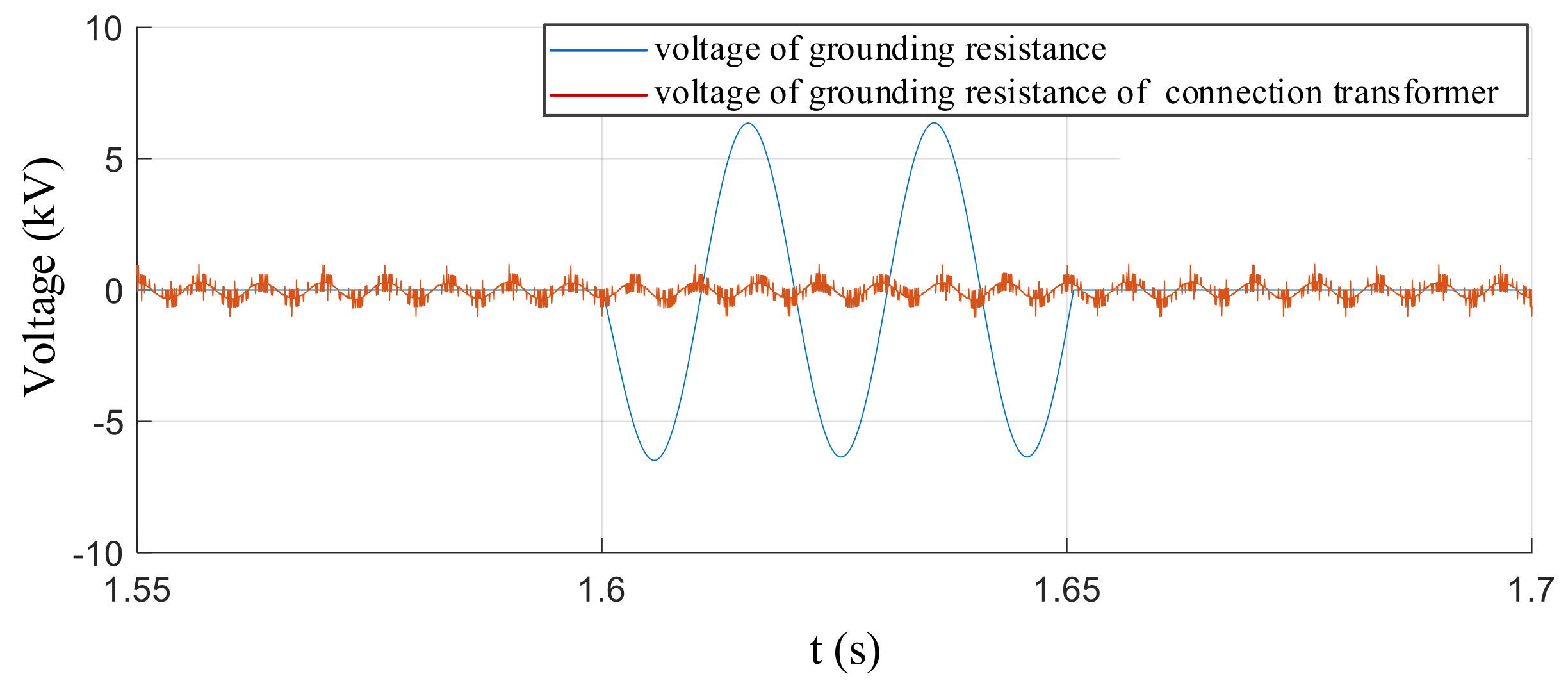
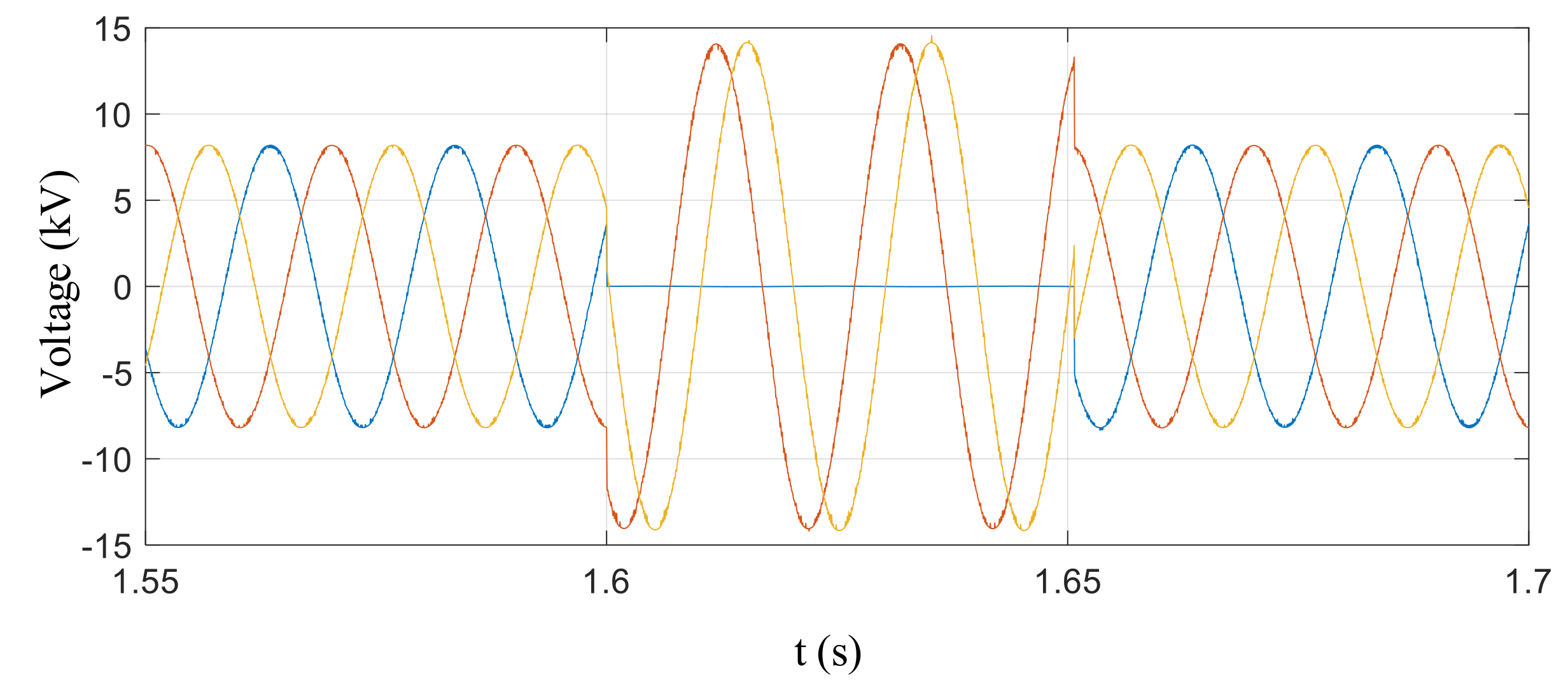
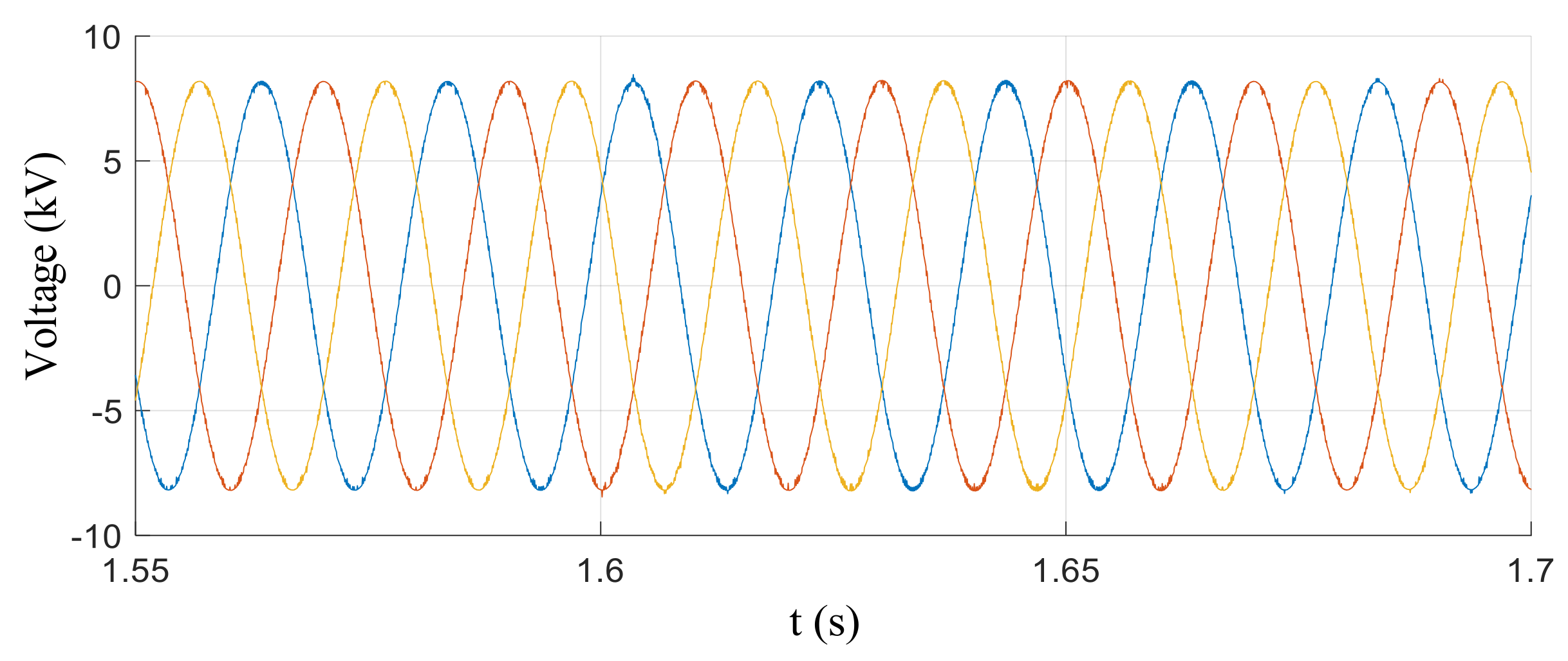
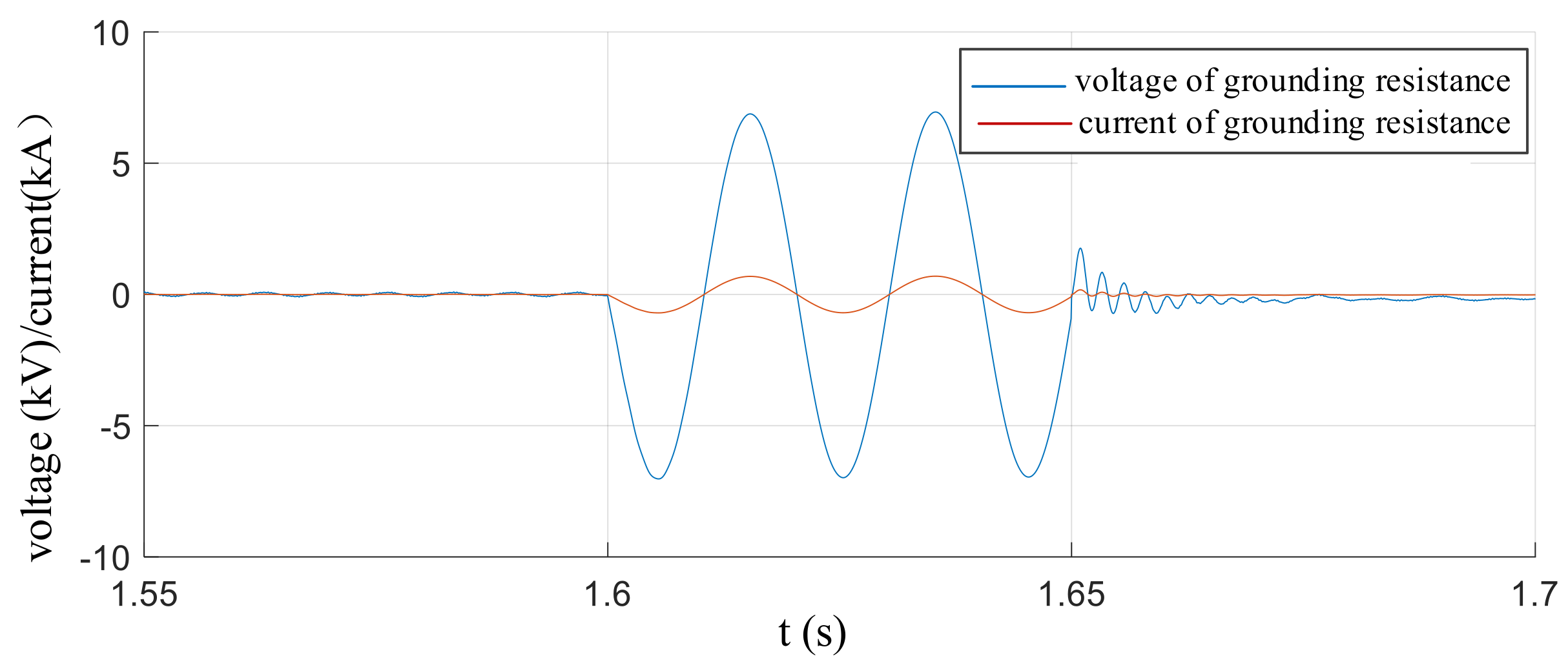
3.2.2. 10 kV AC System-Side Fault

The fault occurring in the 10 kV AC system mainly considers the single-ground short-circuit fault and the phase-to-phase short-circuit fault. Among them, the phase-to-phase short-circuit fault only considers the most serious three-phase-to-ground short circuit fault. Considering the influence of the distributed resistance and the distributed inductance of cable on fault characteristics, the fault current at the outlet of the 110/10 kV transformer is the largest. Therefore, only the simulation condition that the fault point is set at the 10 kV AC bus side and at the outlet of the 110/10 kV transformer is considered. In the simulation, the fault introduction time is set to 1.6 s, and the fault duration is 0.04 s. During the fault, the voltage and current levels at the key locations of the AC and DC sides of the DC distribution system are shown in Table 5.
It can be seen from Table 5 that, when the AC system has a single-phase ground fault, the zero-sequence component appears in the AC system under the condition of configuring the connection transformer. When the three phase-to-ground short-circuit fault occurs in the 10 kV AC bus, the current flowing through 10 kV AC bus increases sharply, and the maximum current is 29.29 kA. This current will be transmitted to the side of the converter valve through the connection transformer, which will increase the current in the converter valve and the bridge-arm reactor accordingly, thus generating overvoltage on the bridge-arm reactor.
The voltage across the neutral point grounding resistance of the grounding transformer and the current waveform flowing through the grounding resistance are shown in Figure 6 and Figure 7, respectively. The voltage waveform of the 10 kV AC bus to ground is shown in Figure 8. It can be seen from the figure that the voltage of the fault phase goes to zero, and the voltage of the non-fault phase rises; but in the small resistance grounding system, the voltage rise value is lower than the line voltage. The maximum voltage across the grounding resistance is 6.49 kV. Under the isolation of the connection transformer, the DC side voltage and current are almost unaffected, and the voltage and current multiples are all one.
According to the above analysis, when the single-phase grounding fault occurs in the 10 kV AC system, the voltage of the AC bus and the DC bus at the valve side is almost unaffected due to the isolation effect of the connection transformer. If the protection action is not taken into account when the three phase-to-ground short circuit fault occurs in the 10 kV AC system, the maximum current flowing through the converter valve is 2.63 kA, the maximum overvoltage generated on the bridge-arm reactor is 7.61 kV, and the maximum current flowing through the DC line is 2.04 kA.

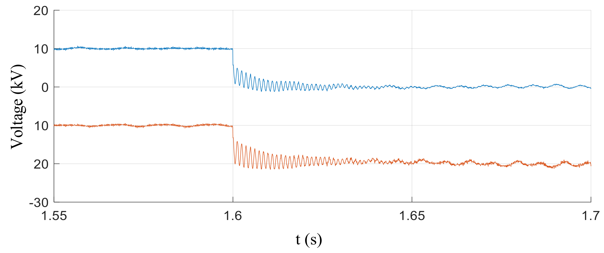
3.2.3. 10 kV DC System-Side Fault

The DC side fault analysis focuses on whether the DC side fault will be transmitted to the AC system side, thus affecting the normal operation of the AC system. This section mainly considers the DC side single-pole grounding fault and bipolar short-circuit fault. Considering the influence of the distributed resistance and the distributed inductance of cable on fault characteristics, the fault current at the outlet of the converter station is the largest. Therefore, the fault point is set at the 10 kV DC bus side and at the outlet of the converter in Tangjia Station during simulation. The time of introducing the fault is 1.6 s. The duration of the single-pole grounding fault is 1.0 s and that of the bipolar short-circuit fault is 0.005 s. In the simulation calculation, the fault is in self-clearing mode without considering the protection action. During the fault, the calculation results of overvoltage and overcurrent at critical locations are shown in Table 6.
Table 6 shows that the single-pole grounding fault has little effect on the voltage of the AC bus, while the voltage of the 10 kV AC bus increases slightly to the ground. As shown in Figure 9, the voltage at both ends of the grounding resistance of the AC system is not affected. As shown in Figure 10, under the DC side bipolar short-circuit fault, the system flows through a large short-circuit current, which will produce a large overvoltage on the DC reactor and bridge-arm reactor.
According to the above analysis, when the single-pole grounding fault occurs on the DC side, the voltage and current on the AC system side are almost unaffected by the isolation of the connection transformer. When the bipolar short-circuit fault occurs on the DC side, the maximum overcurrent of the converter valve and the bridge-arm reactor flows through the converter valve is 1.79 kA without considering the blocking of the converter valve and the action of the DC circuit breaker, and the maximum current transmitted to the 10 kV AC bus is 1.89 kA.

4. System Configuring with no Connection Transformer

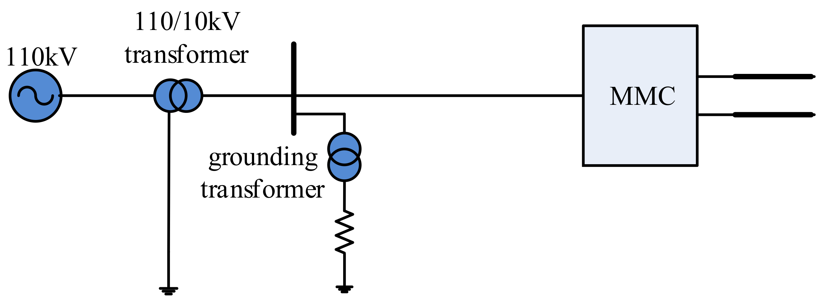
4.1. Access Mode for no Connection Transformer

When the DC distribution system is not configured with the connection transformer, the converter is directly connected to the 10 kV AC bus through the AC reactor. Therefore, it is necessary to consider the interaction between AC and DC distribution systems, which includes the influence of AC-side faults on the DC-side voltage and current, and the influence of DC-side faults on the AC-side voltage and current.
According to the difference of the grounding mode of the 10 kV AC distribution system, the grounding mode of the DC system is also different. As shown in Figure 11, all 10 kV AC distribution systems are grounded by grounded transformers through a small resistance (10 Ω), which can be used as a reference point of ground potential on the DC side. The influence of the grounding mode is mainly reflected in the grounding fault. When the single-phase grounding fault occurs on the DC side, the fault point and the AC-side grounding point form a circuit, while the AC-side grounding resistance value is low, and the circuit will flow through a large current. If the system continues to operate, the larger DC current will have a greater impact on the underground pipeline network and the surrounding communication equipment; moreover, the larger current amplitude flowing through the neutral point when the fault occurs, the overcurrent protection of the AC distribution system will quickly remove the fault, leading to the immediate outage of the DC system. In summary, under this system connection, the normal operation of the AC/DC distribution system will be affected when the DC distribution system occurs a single-pole grounding fault, which greatly reduces the power supply reliability of the system.

4.2. System Simulation Analysis

In this section, based on the topological structure and system parameters of the DC distribution system without a connection transformer, the system simulation model is established to simulate the faults on the AC side and the DC side. According to the simulation results, the influence of AC side faults on DC side voltage and current, and the influence of DC side faults on AC side voltage and current, are analyzed.

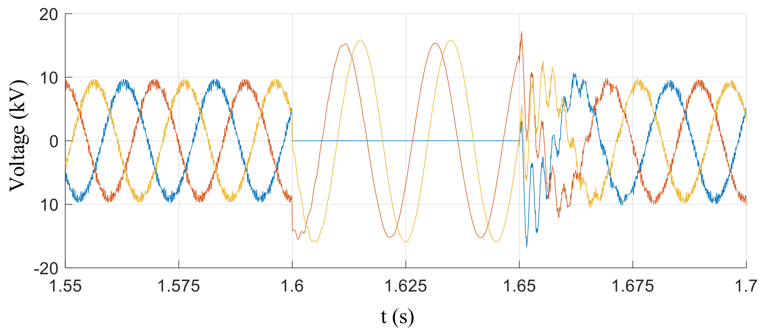
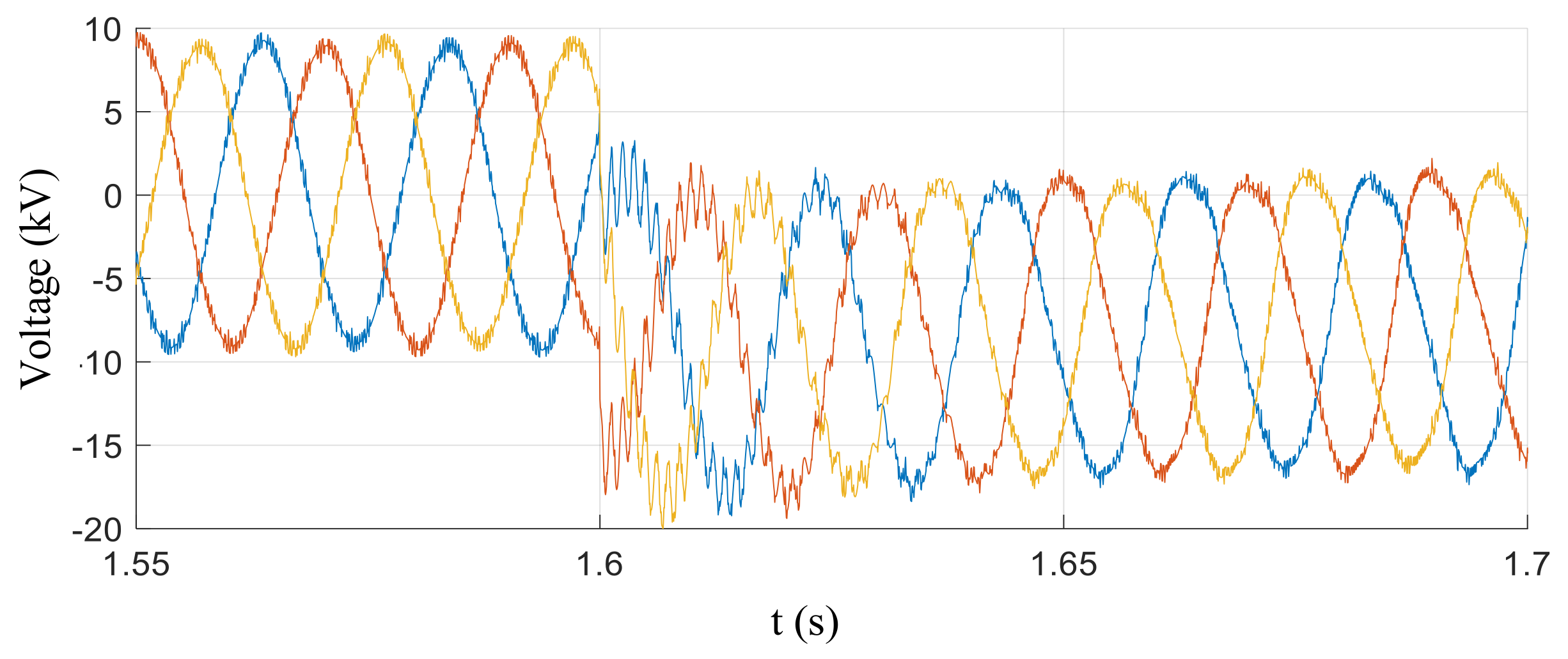
4.2.1. 10 kV AC System-Side Fault

The 10 kV AC system side fault mainly considers the single-ground short-circuit fault and the phase-to-phase short-circuit fault on the 10 kV AC bus side. In the simulation, the fault introduction time is set to 1.6 s, and the fault duration is 0.05 s. During the fault, the voltage and current levels at the key locations of the AC and DC sides of the DC distribution system are shown in Table 7.
It can be seen from Table 7 that, when the AC system has a single-phase ground fault, the zero-sequence voltage component appears in the AC system. Under the action of the zero-sequence voltage component of the AC system, zero-sequence components with the same amplitude and phase appear between positive and negative poles of the DC line to ground voltage, as shown in Figure 12.
It can be seen from Table 7 that, when the three-phase-to-ground short-circuit fault occurs in 10 kV AC bus, because the system is a small resistance grounding system, the short-circuit current will increase sharply, so that the current flowing through the converter valve and the DC line will increase significantly, and the current flowing through the converter valve and bridge-arm reactor will rise to 2.25 kA, which puts forward higher requirements for the current flowing ability of the power electronic devices of the converter valve. The increase of the current also makes the voltage of the bridge arm and both ends of the reactor rises significantly, reaching to about 7.71 kV, which has a certain impact on its insulation level. The maximum current flowing through the DC line is 1.45 kA, and the maximum overvoltage generated at both ends of the DC reactor is 10.11 kV. The voltage waveform at both ends of the neutral grounding resistance of the grounding transformer and the current waveform flowing through the resistance are shown in Figure 13. The waveform of ground voltage of the 10 kV AC bus is shown in Figure 14.
It can be seen from the graph that the ground voltage of the fault phase will jump to zero and the voltage of the non-fault phase will rise, but because of the small resistance grounding system, the voltage is lower than the line voltage. After the fault is cleared, a large transient overvoltage will appear.

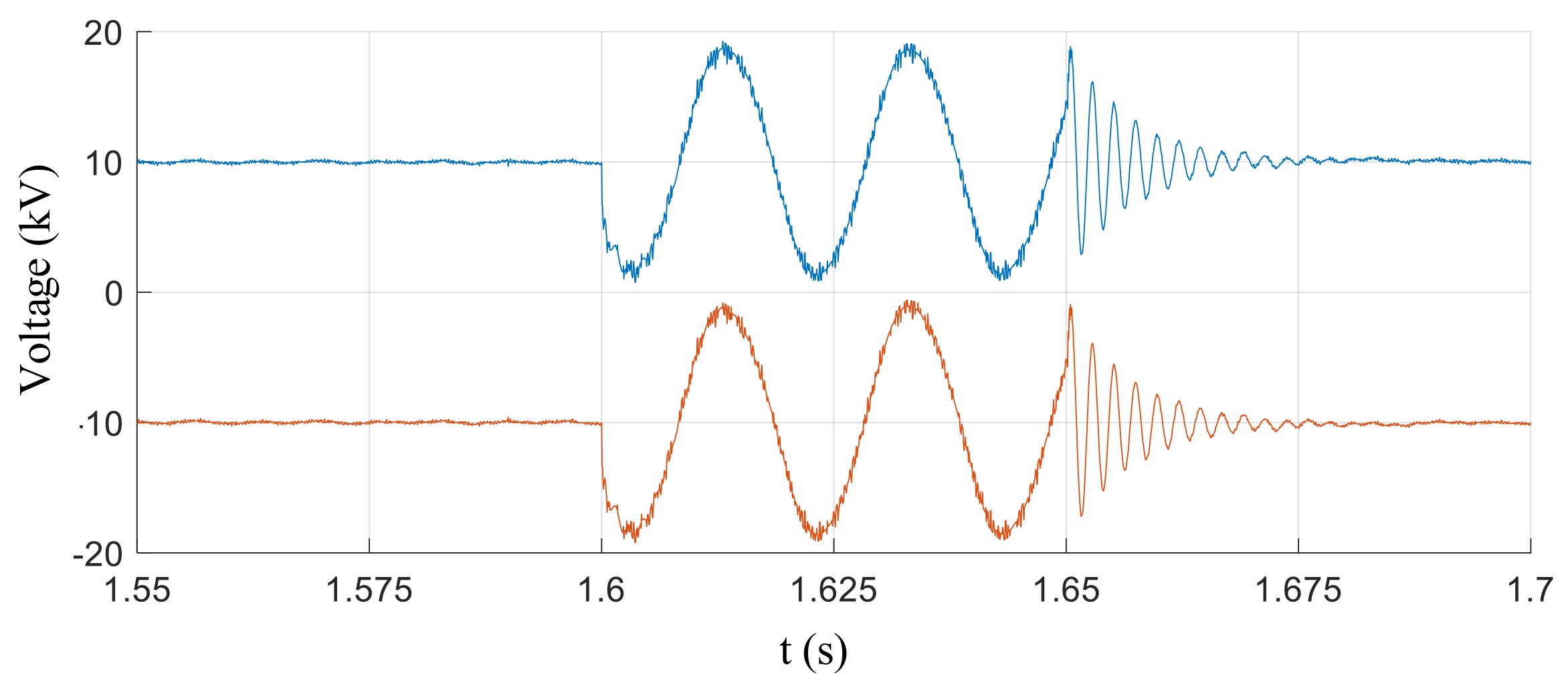
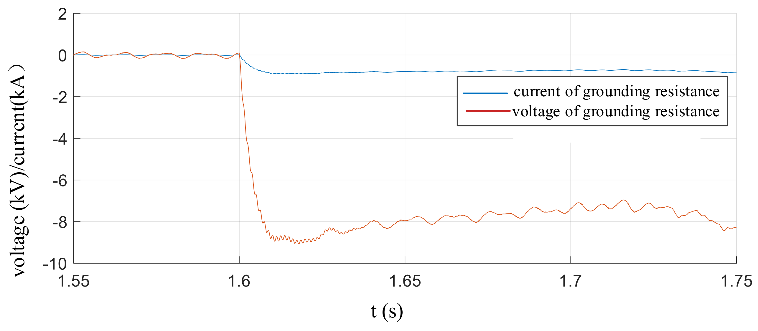
4.2.2. 10 kV DC System-Side Fault

This section mainly considers the DC side single-pole grounding fault and bipolar short-circuit fault. The time of introducing the fault is 1.6 s. The duration of the single-pole grounding fault is 1.0 s and that of the bipolar short-circuit fault is 0.005 s. In the simulation calculation, the fault is in self-clearing mode without considering the protection action. During the fault, the calculation results of overvoltage and overcurrent at critical locations are shown in Table 8.
The waveform of the voltage of single-pole to ground is shown in Figure 15, when the single-pole grounding fault occurs on the DC side. It can be seen from the graph that the voltage of the fault pole becomes zero and the voltage of the non-fault pole jumps twice as much as the normal operation. There is a short transition process in the process of change. The waveform of voltage at both ends of the grounding resistance and the current flowing through the grounding resistance are shown in Figure 16. The neutral grounding point of the AC system jumps to the negative value of the fault pole voltage, that is −9.7 kV, and the current flowing through the grounding resistance is about 1 kA. Figure 17 shows the voltage waveform of the single-pole to ground of the 10 kV AC bus when the DC side single-pole grounding fault occurs. Due to the voltage change of the ground point, the relative ground voltage of the 10 kV AC system deviates as a whole, and the maximum overvoltage value is −20.22 kV. That is to say, the DC side fault is transmitted to the 10 kV AC system side, which makes the AC system produce large overvoltage and overcurrent. The protection of the AC system will act, which will affect the continuous operation of both the DC system and the AC system.
Table 8 shows that when the bipolar short circuit fault occurs on the DC side, there will be a large short-circuit current in the fault circuit, which causes a sharp increase in the current flowing through the converter valve and the bridge-arm reactor, thus causing a high overvoltage on the DC reactor and the bridge-arm reactor. The voltage at both ends of the bridge arm and the unipolar voltage of the DC line to the ground rise to a higher level.
In conclusion, if the system is not configured with a connection transformer and the AC system is grounded by small resistance, when the DC system fault occurs, the converter valve and bridge-arm reactor will flow through a large short-circuit current, which seriously affects the safety of the converter and reactor. At the same time, faults on the DC side will also be transmitted to the AC system side, which affects not only the reliable operation of the DC system, but also the reliable operation of the AC system.

5. Conclusions

The access mode of the three-terminal flexible DC power distribution system to the AC system is studied in the paper, and the conclusions are shown as follows:
(1)
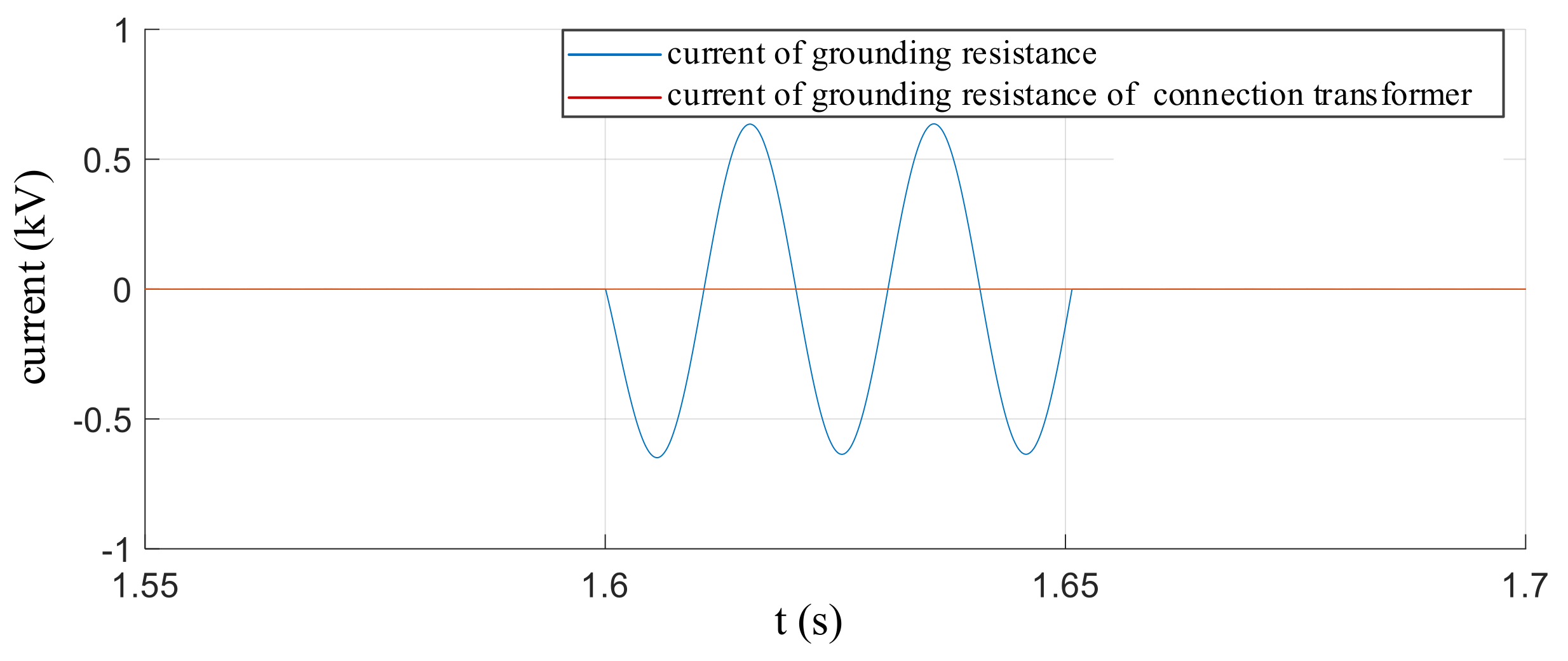
The configuration of the connection transformer can effectively isolate the interaction between the AC and the DC system, and can ensure that the continuous operation under the DC single-pole ground fault without affecting the operation of the 10 kV AC bus, thereby greatly improving the reliability of the power supply of the AC–DC hybrid power distribution system.
(2)
If the system is not configured with a connection transformer and the AC system side is grounded by small resistance, the fault current generated by the fault of the AC system side will be transmitted to the DC side, which greatly increases the current through the converter valve and DC line, and generates large overvoltage at both ends of the DC reactor, which will cause great harm to the continuous operation of the DC system. The faults on the DC side will cause the grounding resistance of the AC system side to flow through a large current, and the AC system side will produce a large overvoltage and overcurrent, which will affect the continuous operation of the AC and DC system.
To sum up, when no connection transformer is installed, the fault will cause a great impact between the AC and the DC system and will increase the cost of converter valves and DC reactor. Configuring the connection transformer can effectively isolate the interaction between the AC and DC systems, while saving costs, greatly improving the operational feasibility of the system. Therefore, it is suggested to configure the connection transformer in the DC distribution system.

Author Contributions

Conceptualization, R.Z. and J.C.; methodology, L.Q. and Z.Y.; software, Z.N.; validation, Y.L., L.Q. and J.C.; formal analysis, Z.Y.; investigation, L.Q.; resources, Y.L.; data curation, Z.N.; writing—original draft preparation, L.Q.; writing—review and editing, Y.L.; visualization, Z.Y.; supervision, Z.N.; project administration, J.C.; funding acquisition, R.Z.

Funding

This research was funded by the ‘smart energy demonstration project of city-park dual-level ‘Internet +’ supporting the energy consumption revolution’.

Conflicts of Interest

The authors declare no conflicts of interest.

References

  1. Song, Q.; Zhao, B.; Liu, W.; Zeng, R. Overview of research on intelligent DC power grid. Chin. J. Electr. Eng. 2013, 33, 9–19. [Google Scholar]
  2. Riccobono, A.; Santi, E. Comprehensive review of stability criteria for DC power distribution systems. IEEE Trans. Ind. Appl. 2014, 50, 3525–3535. [Google Scholar] [CrossRef]
  3. Jiang, D.; Zheng, H. Research status and prospect of DC power grid. Power Syst. Autom. 2012, 36, 98–104. [Google Scholar]
  4. Tabari, M.; Yazdani, A. Stability of a DC distribution system for power system integration of plug-in hybrid electric vehicles. IEEE Trans. Smart Grid. 2014, 5, 2564–2573. [Google Scholar] [CrossRef]
  5. Cui, F.; Guo, J.; Jing, P.; Pan, B.; Hou, Y. Overview of DC distribution technology. Grid Technol. 2014, 38, 556–564. [Google Scholar]
  6. Zhou, H.; Qiu, W.; Sun, K.; Chen, J.; Deng, X.; Qian, F.; Wang, D.; Bincai, Z.; Li, J.; Li, S.; et al. (Eds.) Ultra-High Voltage AC/DC Power Transmission; Springer: Berlin, Germany, 2018; ISBN 978-3662545737. [Google Scholar]
  7. Qu, L.; Yu, Z.; Song, Q.; Yuan, Z.; Zhao, B.; Yao, D.; Chen, J.; Liu, Y.; Zeng, R. Planning and analysis of the demonstration project of the MVDC distribution network in Zhuhai. Front. Energy 2019, 13, 120–130. [Google Scholar] [CrossRef]
  8. Yu, Y.; Jiang, D.; Liang, Y.; Chen, J. Research on the transformerless connection mode for DC power distribution system. J. Eng. 2019, 16, 3378–3382. [Google Scholar] [CrossRef]
  9. Lin, Z. Multi-terminal HVDC-flexible transmission system and its main wiring of Nan’ao island. Autom. Appl. 2014, 10, 76–78. [Google Scholar]
  10. Han, Y.; He, Q.; Zhao, Y.; Guo, Z.; Yao, S.; Li, L. Access mode of intelligent distribution network to AC network based on flexible DC technology. Autom. Electr. Power Syst. 2016, 13, 141–146. [Google Scholar]
  11. Meng, X.; Li, K.; Wang, Z.; Huo, X.; Wu, H.; Zhang, M. A hybrid MMC topology and its DC-fault ride-through capability analysis when applied to MTDC system. Autom. Electr. Power Syst. 2015, 39, 72–79. [Google Scholar]
  12. Yu, X.; Wei, Y.; Jiang, Q.; Xie, X.; Liu, Y.; Wang, K. A Novel Hybrid-arm Bipolar MMC Topology with DC Fault Ride-through Capability. IEEE Trans. Power Deliv. 2016, 32, 1404–1413. [Google Scholar] [CrossRef]
  13. Wu, J.; Yao, L.; Wang, Z.; Li, Y. The Study of MMC Topologies and Their DC Fault Current Blocking Capacities in DC Grid. Proc. CSEE 2015, 35, 2681–2694. [Google Scholar]
  14. Bin, L.; Ye, L.; He, J. Research on the key properties of MMC sub-modules with DC fault eliminating capability. Proc. CSEE 2016, 36, 2114–2122. [Google Scholar]
  15. Xue, Y.; Xu, Z. On the bipolar MMC-HVDC topology suitable for bulk power overhead line transmission: Configuration, control, and DC fault analysis. IEEE Trans. Power Deliv. 2014, 29, 2420–2429. [Google Scholar] [CrossRef]
  16. Li, C.; Zhao, C.; Xu, J.; Ji, Y.; Zhang, F.; An, T. A Pole-toPole Short-Circuit Fault Current Calculation Method for DC Grids. IEEE Trans. Power Deliv. 2017, 32, 4943–4953. [Google Scholar] [CrossRef]
  17. He, Q.; Han, Y.; Li, L.; Zhao, Y.; Liu, G.; Yao, S. Study on the overvoltage and insulation coordination of flexible DC power distribution network. In Proceedings of the 2014 IEEE PES Asia-Pacific Power and Energy Engineering Conference (APPEEC), Hong Kong, China, 7–10 December 2014; pp. 1–5. [Google Scholar]
  18. Guo, X.; Cui, X.; Qi, L. DC Short-circuit Fault Analysis and Protection for the Overhead Line Bipolar MMC-HVDC System. Proc. CSEE 2017, 37, 2177–2184. [Google Scholar]
Figure 1. System structure of a flexible DC power distribution system.
Energies 12 04002 g001
Figure 2. Converter Topology of Tangjia Station and Jishan II Station.
Energies 12 04002 g002
Figure 3. Topology of MMC based on Integrated Gate Commutated Thyristors (IGCT) cross-clamped.
Energies 12 04002 g003
Figure 4. Equivalent circuit of capacitance discharge in the sub-module.
Energies 12 04002 g004
Figure 5. Diagram of the DC distribution system with connection transformers.
Energies 12 04002 g005
Figure 6. Voltage waveform across the neutral point grounding resistance.
Energies 12 04002 g006
Figure 7. Current waveform flowing through the grounding resistance.
Energies 12 04002 g007
Figure 8. Voltage waveform of the ground of the 10 kV AC bus.
Energies 12 04002 g008
Figure 9. Voltage waveform of the AC bus under the single-pole grounding fault.
Energies 12 04002 g009
Figure 10. Voltage waveform of the AC bus under the bipolar short-circuit fault.
Energies 12 04002 g010
Figure 11. Diagram of the DC distribution system without connection transformers.
Energies 12 04002 g011
Figure 12. Single-pole to ground voltage waveform of the DC line.
Energies 12 04002 g012
Figure 13. Voltage and current waveform of grounding resistance.
Energies 12 04002 g013
Figure 14. Relative ground voltage waveform of the 10 kV AC bus.
Energies 12 04002 g014
Figure 15. Voltage waveform of the DC-side single-pole to ground.
Energies 12 04002 g015
Figure 16. Voltage and current waveform of grounding resistance.
Energies 12 04002 g016
Figure 17. Relative ground voltage waveform of the 10 kV AC bus.
Energies 12 04002 g017
Table 1. Parameters of the converter.
Tangjia StationJishan I StationJishan II Station
Rated capacity (MVA)201010
Reactive output range (Mvar)−10~10−5~5−5~5
Rated DC voltage (kV)±10±10±10
Rated DC current (A)1000500500
Rated AC voltage (kV)10.510.510.5
Rated AC current (A)1155577577
Rated current of bridge arm(A)666333333
Table 2. Type and capacity of source, storage and load in a 10 kV AC/DC hybrid distribution network.
VoltageSourceStorageLoad
10 kVJishan I Station 10 MW00
Jishan II Station 10 MW
Tangjia Station 20 MW
±375 V Photovoltaic(PV) 0.7 MW1 MW1 MW charging pile
500 kW DC load
500 kW AC load
Table 3. Voltage levels in different areas during normal operation.
Key PositionVoltage (kV)
110 kV AC bus to ground90.2
10 kV AC bus to ground8.3
Both ends of bridge-arm reactor1.0
Both ends of bridge arm20.6
DC reactor valve-side to ground10.4
DC reactor line-side to ground10.1
Both ends of DC reactor0.3
10 kV DC bus inter-pole20.7
Both ends of AC system ground resistance0
Table 4. Current levels in different areas during normal operation.
Key PositionCurrent (kA)
110 kV AC bus0.08
10 kV AC bus1.68
Bridge-arm reactor1.06
Positive 10 kV DC bus1
Negative 10 kV DC bus1
AC system ground resistance0
Table 5. Overvoltage and overcurrent levels during the 10 kV AC system side fault.
ParameterKey PositionSingle Phase-to-GroundThree Phase-to-Ground
Overvoltage (Peak Value)10 kV AC bus to ground (kV)8.558.34
Both ends of bridge-arm reactor (kV)4.027.61
Both ends of DC reactor (kV)5.398.79
10 kV DC bus to ground (kV)2016.21
10 kV DC bus inter-pole (kV)20.2123.77
Both ends of ground resistance of connection transformer (kV)00
Overcurrent (Peak Value)10 kV AC bus (kA)1.7629.49
Bridge arm-reactor (kA)12.63
10 kV DC bus (kA)12.04
Ground resistance of connection transformer (kA)00
Fault point (kA)0.229.49
Table 6. Overvoltage and overcurrent levels of different positions during the DC system side fault.
ParameterKey PositionSingle-Pole Grounding FaultBipolar Short-Circuit Fault
Overvoltage
(Peak value)
10kV AC bus to ground (kV)8.478.68
Both ends of bridge-arm reactor (kV)2.346.51
Both ends of DC reactor (kV)6.9145.79
10kV DC bus to ground (kV)27.4618.87
10kV DC bus inter-pole (kV)20.7337.66
Both ends of ground resistance of connection transformer (kV)00
Overcurrent
(Peak value)
10kV AC bus (kA)1.651.89
Bridge arm-reactor (kA)1.011.79
10kV DC bus (kA)13.23
Ground resistance of connection transformer (kA)00
Fault point (kA)1.1711.89
Table 7. Overvoltage and overcurrent levels during the 10 kV AC system side fault.
ParameterKey PositionSingle-GroundThree-Phase-to-Ground
Overvoltage
(Peak Value)
10 kV AC bus to ground (kV)14.2413.67
Both ends of bridge-arm reactor (kV)4.047.71
Both ends of DC reactor (kV)4.0210.11
10 kV DC bus to ground (kV)18.3517.95
10kV DC bus inter-pole (kV)20.5623.20
Both ends of ground resistance of connection transformer (kV)6.272.13
Overcurrent
(Peak Value)
10 kV AC bus (kA)2.6854.45
Bridge arm-reactor (kA)1.232.25
10 kV DC bus (kA)1.451.45
Ground resistance of connection transformer (kA)0.6410.100
Fault point (kA)1.5755.42
Table 8. Overvoltage and overcurrent levels of different positions during the DC system side fault.
ParameterKey PositionSingle-Pole Grounding FaultBipolar Short-Circuit Fault
Overvoltage (Peak value)10 kV AC bus to ground (kV)19.409.45
Both ends of bridge-arm reactor (kV)8.0614.04
Both ends of DC reactor (kV)5.66129.67
10 kV DC bus to ground (kV)24.4428.77
10 kV DC bus inter-pole (kV)22.5356.7
Both ends of ground resistance of connection transformer (kV)9.040.30
Overcurrent (Peak value)10 kV AC bus (kA)2.302.08
Bridge arm-reactor (kA)2.541.7
10 kV DC bus (kA)1.893.05
ground resistance of connection transformer (kA)0.9040.030
Fault point (kA)2.7612.76

