The Role of Domestic Integrated Battery Energy Storage Systems for Electricity Network Performance Enhancement

 ,
,
Abstract
1. Introduction
2. State-of-The-Art Development of Domestic Integrated Batteries
2.1. Generalities about Batteries
2.1.1. Main Components and Working Principles
2.1.2. Chemistries
2.1.3. Battery Ageing and Degradation
2.2. Products Available
2.2.1. Solar PV Batteries
2.2.2. Electric Vehicles’ Batteries Reuse
2.2.3. Performance and Characteristics of Available Systems
2.3. Numerical Modelling of BESS
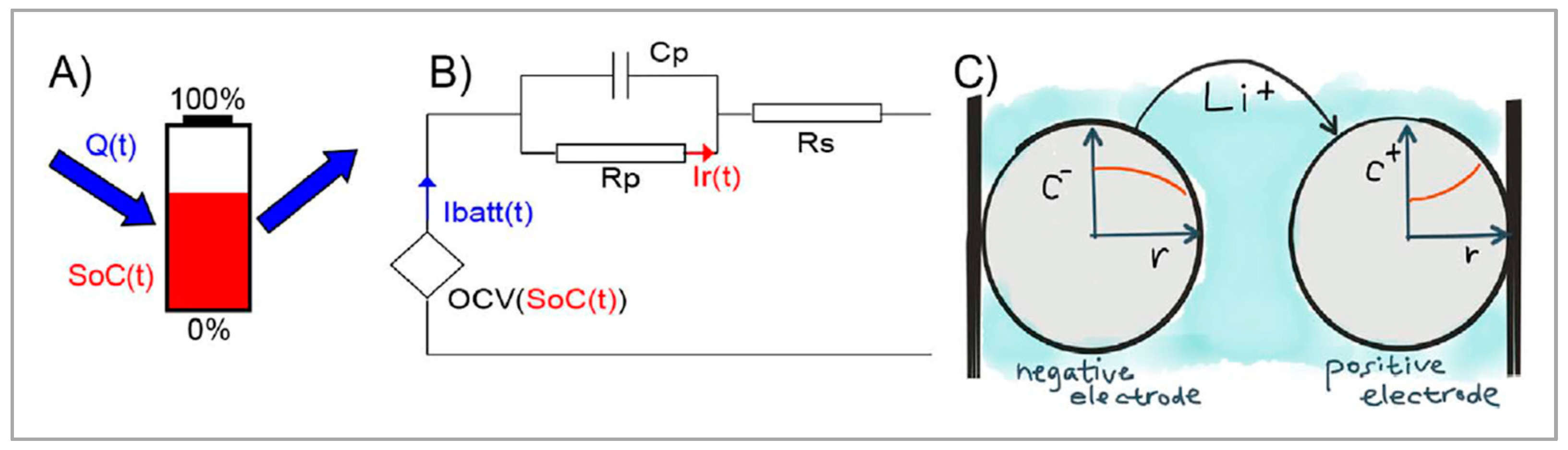
2.3.1. Main Battery Models
- A voltage source (Or Equilibrium Potential) which value is a function of the SOC of the battery, the discharge rate (current) and the temperature.
- Resistors, used to model the “potential losses”: The conductivity of the electrodes and the separator is not infinite, in addition to the effect of concentration gradients of ions near the electrodes and the limits in the kinetics of the chemical reactions. The value of these resistors depends on the chemistry, the geometry, the temperature and the discharge rate of the cell.
- A capacitor in parallel to one of the abovementioned resistors, to model the capacitive effects due to the structure of the cell, leading to electrical polarisation, and pseudo-capacitance (diffusion limited space charges). In other words, this capacitor accounts for transient effects in the cell.
- In some models, other parallel RC circuits maybe added in series, increasing the accuracy of the modelled transient response, adding at the same time complexity and computation time [68].
2.3.2. Electricity Network Modelling
2.3.3. Results from Numerical Simulations
2.4. Trials and Real-Scale Implementation
3. Potential Roles of Domestic Integrated Batteries
3.1. Behind-the-Meter Storage
3.2. Grid Services and Domestic BESS
3.2.1. Services and Applications
3.2.2. Integrated Batteries for Grid Services Provision
3.3. Comparison of BESS with Other Energy Storage Technologies
4. Barriers to Domestic Battery Deployment
5. Conclusions
Author Contributions
Funding
Acknowledgments
Conflicts of Interest
References
- Spiecker, S.; Weber, C. The future of the european electricity system and the impact of fluctuating renewable energy—A scenario analysis. Energy Policy 2014, 65, 185–197. [Google Scholar] [CrossRef]
- Allan, G.; Eromenko, I.; Gilmartin, M.; Kockar, I.; McGregor, P. The economics of distributed energy generation: A literature review. Renew. Sustain. Energy Rev. 2015, 42, 543–556. [Google Scholar] [CrossRef]
- Ekanayake, J.; Liyanage, K.; Wu, J.; Yokoyama, A.; Jenkins, N. SMART GRID—Technology and Applications; Wiley: Hoboken, NY, USA, 2012; ISBN 9780470974094. [Google Scholar]
- Brown, M.H.; Sedano, R.P. Electricity Transmission: A Primer; Natl Conference of State: Denver, CO, USA, 2004; ISBN 1580243525.
- Elombo, A.I.; Morstyn, T.; Apostolopoulou, D.; McCulloch, M.D. Residential load variability and diversity at different sampling time and aggregation scales. In Proceedings of the 2017 IEEE AFRICON, Cape Town, South Africa, 8–20 September 2017; pp. 1331–1336. [Google Scholar]
- Shah, N.N.; Wilson, C.; Huang, M.J.; Hewitt, N.J. Analysis on field trial of high temperature heat pump integrated with thermal energy storage in domestic retrofit installation. Appl. Therm. Eng. 2018, 143, 650–659. [Google Scholar] [CrossRef]
- EirGrid Group plc—Smart Grid Dashboard n.d. Available online: http://smartgriddashboard.eirgrid.com/#ni/demand (accessed on 24 April 2018).
- Mcdonald, J.D.; Wojszczyk, B.; Flynn, B.; Voloh, I. Distribution Systems, Substations, and Integration of Ditributed Generation. In Encyclopedia of Sustainability Science and Technology; Springer: Berlin/Heidelberg, Germany, 2012; pp. 7–68. ISBN 978-0-387-89469-0. [Google Scholar]
- Fitzgerald, G.; Mandel, J.; Morris, J.; Touati, H. The Economics of Battery Energy Storage: How Multi-Use, Customer-Sited Batteries Deliver the Most Services and Value to Customers and the Grid; Rocky Mountain Institute: Boulder, CO, USA, 2015. [Google Scholar]
- European Environment Agency. Air Quality in Europe—2017 Report; European Environment Agency: København, Denmark, 2017; ISBN 978-92-9213-489-1. [Google Scholar]
- Bertoldi, P.; López Lorente, J.; Labanca, N. Energy Consumption and Energy Efficiency Trends in the EU-28 2000–2014; EUR 27972 EN; Publications Office of the European Union: Luxembourg, Luxembourg, 2016; ISBN 9789279593604. [Google Scholar]
- Chaudry, M.; Abeysekera, M.; Reza Hosseini, S.H.; Wu, J.; Jenkins, N. UKERC Energy Strategy under Uncertainties; UK Energy Research Center: London, UK, 2014. [Google Scholar]
- Smith, B.D. Heat Electrification and Sub-Daily Demand Profiles: A Comparison of Great Britain and Norway—Energy Storage Hub n.d. Available online: http://energystoragehub.org/energy-storage-applications/grid-scale/heat-electrification-and-sub-daily-demand-profiles-a-comparison-of-great-britain-and-norway/ (accessed on 21 January 2019).
- Pimm, A.J.; Cockerill, T.T.; Taylor, P.G. The potential for peak shaving on low voltage distribution networks using electricity storage. J. Energy Storage 2018, 16, 231–242. [Google Scholar] [CrossRef]
- Jenkins, N.; Long, C.; Wu, J. An Overview of the Smart Grid in Great Britain. Engineering 2015, 1, 413–421. [Google Scholar] [CrossRef]
- Eyer, J. Electric Utility Transmission and Distribution Upgrade Deferral Benefits from Modular Electricity Storage; Sandia National Laboratories: Albuquerque, New Mexico; Livermore, CA, USA, 2009.
- Deeba, S.R.; Sharma, R.; Saha, T.K.; Chakraborty, D.; Thomas, A. Evaluation of technical and financial benefits of battery-based energy storage systems in distribution networks. IET Renew. Power Gener. 2016, 10, 1149–1160. [Google Scholar] [CrossRef]
- Amirante, R.; Cassone, E.; Distaso, E.; Tamburrano, P. Overview on recent developments in energy storage: Mechanical, electrochemical and hydrogen technologies. Energy Convers. Manag. 2017, 132, 372–387. [Google Scholar] [CrossRef]
- Akinyele, D.O.; Rayudu, R.K. Review of energy storage technologies for sustainable power networks. Sustain. Energy Technol. Assess. 2014. [Google Scholar] [CrossRef]
- Beardsall, J.C.; Gould, C.A.; Al-Tai, M. Energy Storage Systems: A Review of the Technology and Its Application in Power Systems. Power Eng. 2015. [Google Scholar] [CrossRef]
- Koohi-Kamali, S.; Tyagi, V.V.; Rahim, N.A.; Panwar, N.L.; Mokhlis, H. Emergence of energy storage technologies as the solution for reliable operation of smart power systems: A review. Renew. Sustain. Energy Rev. 2013. [Google Scholar] [CrossRef]
- Lund, P.D.; Lindgren, J.; Mikkola, J.; Salpakari, J. Review of energy system flexibility measures to enable high levels of variable renewable electricity. Renew. Sustain. Energy Rev. 2015, 45, 785–807. [Google Scholar] [CrossRef]
- Yekini Suberu, M.; Wazir Mustafa, M.; Bashir, N. Energy storage systems for renewable energy power sector integration and mitigation of intermittency. Renew. Sustain. Energy Rev. 2014, 35, 499–514. [Google Scholar] [CrossRef]
- Guney, M.S.; Tepe, Y. Classification and assessment of energy storage systems. Renew. Sustain. Energy Rev. 2017. [Google Scholar] [CrossRef]
- Hull, R.; Jones, A. Development of Decentralised Energy and Storage Systems in the UK; A Report for the Renewable Energy Association; KPMG: Amstelveen, The Netherlands, 2016. [Google Scholar]
- World Energy Council World Energy Resources—E-Storage. World Energy Counc. Rep. 2016, 1, 468.
- Aichhorn, A.; Greenleaf, M.; Li, H.; Zheng, J. A cost effective battery sizing strategy based on a detailed battery lifetime model and an economic energy management strategy. IEEE Power Energy Soc. Gen. Meet. 2012, 1–8. [Google Scholar] [CrossRef]
- Das, C.K.; Bass, O.; Kothapalli, G.; Mahmoud, T.S.; Habibi, D. Overview of energy storage systems in distribution networks: Placement, sizing, operation, and power quality. Renew. Sustain. Energy Rev. 2018. [Google Scholar] [CrossRef]
- Johnson, R.C.; Mayfield, M.; Beck, S.B.M. Optimal placement, sizing, and dispatch of multiple BES systems on UK low voltage residential networks. J. Energy Storage 2018, 17, 272–286. [Google Scholar] [CrossRef]
- Müller, M.; If, T.D.; Viernstein, L.; Nam, C.; Eiting, A.; Hesse, H.C.; Witzmann, R.; Jossen, A. Evaluation of grid-level adaptability for stationary battery energy storage system applications in Europe. J. Energy Storage 2017, 9, 1–11. [Google Scholar] [CrossRef]
- Hoppmann, J.; Volland, J.; Schmidt, T.S.; Hoffmann, V.H. The economic viability of battery storage for residential solar photovoltaic systems—A review and a simulation model. Renew. Sustain. Energy Rev. 2014. [Google Scholar] [CrossRef]
- Khalilpour, R.; Vassallo, A. Planning and operation scheduling of PV-battery systems: A novel methodology. Renew. Sustain. Energy Rev. 2016, 53, 194–208. [Google Scholar] [CrossRef]
- Linden, D.; Reddy, T.B. (Eds.) Handbook of Batteries, 3rd ed.; McGraw-Hill: Blackclick, OH, USA, 2002; ISBN 0071359788. [Google Scholar] [CrossRef]
- Buchmann, I. BU-908: Battery Management System (BMS)—Battery University n.d. Available online: https://batteryuniversity.com/learn/article/how_to_monitor_a_battery (accessed on 8 October 2019).
- Battery IInformation Table of Contents, Basic to Advanced n.d. Available online: http://batteryuniversity.com/learn/ (accessed on 4 December 2017).
- Chen, H.; Cong, T.N.; Yang, W.; Tan, C.; Li, Y.; Ding, Y. Progress in electrical energy storage system: A critical review. Prog. Nat. Sci. 2009, 19, 291–312. [Google Scholar] [CrossRef]
- Kularatna, N. ENERGY STORAGE DEVICES FOR ELECTRONIC SYSTEMS—Rechargeable Batteries and Supercapacitors; Hayton, J., Ed.; Elsevier: Amsterdam, The Netherlands, 2015. [Google Scholar]
- Isidor Buchmann. How does the Lead Acid Battery Work? Battery University, 2018. Available online: https://batteryuniversity.com/learn/article/lead_based_batteries (accessed on 15 August 2018).
- Buchmann, I. Nickel-based Batteries—Battery University. 2018. Available online: http://batteryuniversity.com/learn/article/nickel_based_batteries (accessed on 29 June 2018).
- Buchmann, I. Types of Lithium-Ion Batteries—Battery University. 2018. Available online: http://batteryuniversity.com/learn/article/types_of_lithium_ion (accessed on 3 July 2018).
- Garg, B. Introduction to Flow Batteries: Theory and Applications. 2011. Available online: http://large.stanford.edu/courses/2011/ph240/garg1/ (accessed on 4 July 2018).
- Scrosati, B. History of lithium batteries. J. Solid State Electrochem. 2011, 15, 1623–1630. [Google Scholar] [CrossRef]
- Kabir, M.M.; Demirocak, D.E.; Dotterweich, F.H. Degradation mechanisms in Li-ion batteries: A state-of- the-art review. Int. J. Energy Res. 2017, 41, 1963–1986. [Google Scholar] [CrossRef]
- Isidor Buchmann. Capacity Loss and Discovering What Causes a Battery to Fade—Battery University. 2016. Available online: http://batteryuniversity.com/learn/article/capacity_loss (accessed on 28 June 2018).
- Vetter, J.; Novák, P.; Wagner, M.R.; Veit, C.; Möller, K.C.; Besenhard, J.O.; Winter, M.; Wohlfahrt-Mehrens, M.; Vogler, C.; Hammouche, A. Ageing mechanisms in lithium-ion batteries. J. Power Sources 2005, 147, 269–281. [Google Scholar] [CrossRef]
- Rao, Z.; Wang, S. A review of power battery thermal energy management. Renew. Sustain. Energy Rev. 2011, 15, 4554–4571. [Google Scholar] [CrossRef]
- Al-Zareer, M.; Dincer, I.; Rosen, M.A. A review of novel thermal management systems for batteries. Int. J. Energy Res. 2018, 1–24. [Google Scholar] [CrossRef]
- Wankmüller, F.; Thimmapuram, P.R.; Gallagher, K.G.; Botterud, A. Impact of battery degradation on energy arbitrage revenue of grid-level energy storage. J. Energy Storage 2017, 10, 56–66. [Google Scholar] [CrossRef]
- Reniers, J.M.; Mulder, G.; Ober-Blöbaum, S.; Howey, D.A. Improving optimal control of grid-connected lithium-ion batteries through more accurate battery and degradation modelling. J. Power Sources 2018, 379, 91–102. [Google Scholar] [CrossRef]
- Rappaport, R.D.; Miles, J. Cloud energy storage for grid scale applications in the UK. Energy Policy 2017, 109, 609–622. [Google Scholar] [CrossRef]
- Staffell, I.; Rustomji, M. Maximising the value of electricity storage. J. Energy Storage 2016, 8, 212–225. [Google Scholar] [CrossRef]
- BEIS; Ofgem. Upgrading Our Energy System—Smart Systems and Flexibility Plan; Ofgem: London, UK, 2017; pp. 1–32. [Google Scholar]
- Neubauer, J.; Simpson, M. Deployment of Behind-The-Meter Energy Storage for Demand Charge Reduction; Technical Report NREL/TP-5400-63162; National Renewable Energy Laboratory: Golden, CO, USA, 2015; p. 30.
- Muenzel, V.; Mareels, I.; De Hoog, J.; Vishwanath, A.; Kalyanaraman, S.; Gort, A. PV generation and demand mismatch: Evaluating the potential of residential storage. In Proceedings of the 2015 IEEE Power & Energy Society Innovative Smart Grid Technologies Conference (ISGT), Washington, DC, USA, 18–20 February 2015. [Google Scholar]
- Günter, N.; Marinopoulos, A. Energy storage for grid services and applications: Classification, market review, metrics, and methodology for evaluation of deployment cases. J. Energy Storage 2016, 8, 226–234. [Google Scholar] [CrossRef]
- Svarc, J. Complete Solar Battery Review—Clean Energy Reviews. 2018. Available online: https://www.cleanenergyreviews.info/blog/2015/11/19/complete-battery-storage-comparison-and-review (accessed on 8 June 2018).
- Powerwall 2 AC Specifications n.d. Available online: https://www.energymatters.com.au/wp-content/uploads/2016/11/tesla-powerwall-2-datasheet.pdf (accessed on 9 October 2019).
- Powerwall 2 Full Specs Reveal Cheap Storage And Limited Warranty n.d. Available online: https://www.solarquotes.com.au/blog/powerwall-2-warranty/ (accessed on 9 October 2019).
- Lg Chem Resu Datasheet n.d.:1–2. Available online: https://solarclarity.nl/wp-content/uploads/2018/07/LG-Chem-RESU-13.pdf (accessed on 9 October 2019).
- Svarc, J. Lithium Vs Lead-Acid Batteries—Clean Energy Reviews. 2019. Available online: https://www.cleanenergyreviews.info/blog/simpliphi-pylontech-narada-bae-lead-acid-battery (accessed on 9 October 2019).
- SIMPLIPHI PHI Datasheet. 2018. Available online: https://simpliphipower.com/documentation/phi-3-5/simpliphi-power-phi-3-5-kwh-60-amp-specification-sheet.pdf (accessed on 9 October 2019).
- Svarc, J. Sonnen Battery Review—Clean Energy Reviews. 2018. Available online: https://www.cleanenergyreviews.info/blog/sonnen-battery-review (accessed on 9 October 2019).
- sonnenBatterie. Technical Data sonnenBatterie. 2019, 2–3. Available online: https://sonnenbatterie.de/sites/default/files/161018_datasheet_sonnenbatterie.pdf (accessed on 9 October 2019).
- Muoio, D. 10 Home Batteries Competing with Tesla Powerwall 2—Business Insider. 2017. Available online: http://uk.businessinsider.com/rechargeable-battery-options-compete-tesla-2017-5?r=US&IR=T/#8-powervault-is-an-at-home-battery-system-that-is-sold-in-the-uk-all-units-come-with-an-inverter-included-and-the-most-powerful-model-stores-6-kwh-of-energy-prices- (accessed on 12 January 2018).
- Relectrify n.d. Available online: https://www.relectrify.com/ (accessed on 5 July 2018).
- Cunningham, W. For Dead EV Batteries, Reuse comes before Recycle. CNET Road Show. 2017. Available online: https://www.cnet.com/roadshow/news/for-dead-ev-batteries-reuse-comes-before-recycle/ (accessed on 5 July 2018).
- Chris Robinson. Recycle vs Reuse: Why EV Batteries May not Often Get a Second-Life as Stationary Storage Systems. Energy Storage News. 2017. Available online: https://www.energy-storage.news/blogs/recycle-vs-reuse-why-ev-batteries-may-not-often-get-a-second-life-as-statio (accessed on 5 July 2018).
- Seaman, A.; Dao, T.S.; McPhee, J. A survey of mathematics-based equivalent-circuit and electrochemical battery models for hybrid and electric vehicle simulation. J. Power Sources 2014, 256, 410–423. [Google Scholar] [CrossRef]
- Simpkins, T.; Donnell, C.O. Optimizing Battery Sizing and Dispatching To Maximize Economic Return. In Proceedings of the Battcon 2017 International Stationary Battery Conference, At Orlando, FL, USA, 8–10 May 2017. [Google Scholar]
- Gao, L.; Liu, S.; Dougal, R.A. Dynamic lithium-ion battery model for system simulation. IEEE Trans. Components Packag. Technol. 2002, 25, 495–505. [Google Scholar]
- Newman, J.; Tiedemann, W. Porous-electrode theory with battery applications. AIChE J. 1975, 21, 25–41. [Google Scholar] [CrossRef]
- Banerjee, B.; Jayaweera, D.; Islam, S. Modelling and Simulation of Power Systems. In Smart Power Systems and Renewable Energy System Integration; Springer: Berlin/Heidelberg, Germany, 2016; pp. 15–29. ISBN 978-3-319-30425-0. [Google Scholar]
- Andersson, G. Modelling and Analysis of Electric Power Systems; EEH—Power Systems Laboratory: Zurich, Switzerland, 2008. [Google Scholar]
- Hay, S.; Ferguson, A. A Review of Power System Modelling Platforms and Capabilities; IET Special Interest Publication for the Council for Science and Technology; IET: London, UK, 2015; pp. 3–13. [Google Scholar]
- Meneses de Quevedo, P.; Contreras, J. Optimal Placement of Energy Storage and Wind Power under Uncertainty. Energies 2016, 9, 528. [Google Scholar] [CrossRef]
- Sidhu, A.S.; Pollitt, M.G.; Anaya, K.L. A social cost benefit analysis of grid-scale electrical energy storage projects: A case study. Appl. Energy 2018, 212, 881–894. [Google Scholar] [CrossRef]
- Patsios, C.; Wu, B.; Chatzinikolaou, E.; Rogers, D.J.; Wade, N.; Brandon, N.P.; Taylor, P. An integrated approach for the analysis and control of grid connected energy storage systems. J. Energy Storage 2016, 5, 48–61. [Google Scholar] [CrossRef]
- Ru, Y.; Kleissl, J.; Martinez, S. Storage size determination for grid-connected photovoltaic systems. IEEE Trans. Sustain. Energy 2013, 4, 68–81. [Google Scholar] [CrossRef]
- Weniger, J.; Tjaden, T.; Quaschning, V. Sizing of residential PV battery systems. Energy Procedia 2014, 46, 78–87. [Google Scholar] [CrossRef]
- Sani Hassan, A.; Cipcigan, L.; Jenkins, N. Optimal battery storage operation for PV systems with tariff incentives. Appl. Energy 2017, 203, 422–441. [Google Scholar] [CrossRef]
- Pena-Bello, A.; Burer, M.; Patel, M.K.; Parra, D. Optimizing PV and grid charging in combined applications to improve the profitability of residential batteries. J. Energy Storage 2017, 13, 58–72. [Google Scholar] [CrossRef]
- Nottrott, A.; Kleissl, J.; Washom, B. Energy dispatch schedule optimization and cost benefit analysis for grid-connected, photovoltaic-battery storage systems. Renew. Energy 2013, 55, 230–240. [Google Scholar] [CrossRef]
- Angenendt, G.; Zurmühlen, S.; Mir-Montazeri, R.; Magnor, D.; Sauer, D.U. Enhancing Battery Lifetime in PV Battery Home Storage System Using Forecast Based Operating Strategies. Energy Procedia 2016, 99, 80–88. [Google Scholar] [CrossRef]
- Yoon, Y.; Kim, Y.H. Effective scheduling of residential energy storage systems under dynamic pricing. Renew. Energy 2016, 87, 936–945. [Google Scholar] [CrossRef]
- Babacan, O.; Ratnam, E.L.; Disfani, V.R.; Kleissl, J. Distributed energy storage system scheduling considering tariff structure, energy arbitrage and solar PV penetration. Appl. Energy 2017, 1384–1393. [Google Scholar] [CrossRef]
- Yang, Y.; Li, H.; Aichhorn, A.; Zheng, J.; Greenleaf, M. Sizing strategy of distributed battery storage system with high penetration of photovoltaic for voltage regulation and peak load shaving. IEEE Trans. Smart Grid 2014, 5, 982–991. [Google Scholar] [CrossRef]
- Zillmann, M.; Yan, R.; Saha, T.K. Regulation of distribution network voltage using dispersed battery storage systems: A case study of a rural network. In Proceedings of the 2011 IEEE Power and Energy Society General Meeting, Detroit, MI, USA, 24–28 July 2011; pp. 1–8. [Google Scholar] [CrossRef]
- Nazaripouya, H.; Wang, Y.; Chu, P.; Pota, H.R.; Members, R.G. Optimal Sizing and Placement of Battery Energy Storage in Distribution System Based on Solar Size for Voltage Regulation. In Proceedings of the 2015 IEEE Power & Energy Society General Meeting, Denver, CO, USA, 26–30 July 2015. [Google Scholar] [CrossRef]
- Lindstens, J. Study of a Battery Energy Storage System in a Weak Distribution Grid Distribution Grid. Master Thesis, UPPSALA UNIVERSITET, Uppsala, Sweden, 2017. [Google Scholar]
- Marra, F.; Yang, G.; Træholt, C.; Østergaard, J.; Larsen, E. A decentralized storage strategy for residential feeders with photovoltaics. IEEE Trans. Smart Grid 2014, 5, 974–981. [Google Scholar] [CrossRef]
- Zeh, A.; Witzmann, R. Operational strategies for battery storage systems in low-voltage distribution grids to limit the feed-in power of roof-mounted solar power systems. Energy Procedia 2014, 46, 114–123. [Google Scholar] [CrossRef]
- Moshövel, J.; Kairies, K.P.; Magnor, D.; Leuthold, M.; Bost, M.; Gährs, S.; Szczechowicz, E.; Cramer, M.; Sauer, D.U. Analysis of the maximal possible grid relief from PV-peak-power impacts by using storage systems for increased self-consumption. Appl. Energy 2015, 137, 567–575. [Google Scholar] [CrossRef]
- Liu, J.; Zhang, N.; Kang, C.; Kirschen, D.; Xia, Q. Cloud energy storage for residential and small commercial consumers: A business case study. Appl. Energy 2017, 188, 226–236. [Google Scholar] [CrossRef]
- Sonnen, Storage and VPPs. Grey Cells Energy n.d. Available online: https://greycellsenergy.com/examples/sonnens-community-aggregating-domestic-battery-storage/ (accessed on 12 July 2018).
- Williams, D. The Vanguard of Decentralized Energy for Sonnen—Decentralized Energy. 2018. Available online: https://www.decentralized-energy.com/articles/2018/05/the-vanguard-of-decentralized-energy-for-sonnen.html (accessed on 12 July 2018).
- Dale, M.; Hey, R.; Turvey, N.; Swift, P. Project Sola BRISTOL—Closedown Report; University of Bristol: Bristol, UK, 2016. [Google Scholar]
- Northern Powergrid. Innovation Projects—Distributed Storage & Solar Study (NIA_NPG_011) n.d. Available online: https://www.northernpowergrid.com/innovation/projects/distributed-storage-solar-study-nia-npg-011 (accessed on 13 July 2018).
- Puckup, D.; Greene, L.; Dunlop, S.; Barwell, P. Solar + Storage = Opportunities − Solar Trade Association Position Paper on Energy Storage; Solar Trade Association: London, UK, 2016. [Google Scholar]
- Teller, O.; Nicolai, J.-P.; Lafoz, M.; Laing, D.; Tamme, R.; Pedersen, A.S.; Andersson, M.; Folke, C.; Bourdil, C.; Conte, G.; et al. Joint EASE/EERA Recommendations for a European Energy Storage Technology Development Roadmap Towards 2030; Joint European Association for Storage of Energy (EASE); European Energy Research Alliance (EERA): Brussels, Belgium, 2013; Available online: https://www.eera-set.eu/wp-content/uploads/148885-EASE-recommendations-Roadmap-04.pdf (accessed on 12 September 2019).
- Palizban, O.; Kauhaniemi, K. Energy storage systems in modern grids—Matrix of technologies and applications. J. Energy Storage 2016, 6, 248–259. [Google Scholar] [CrossRef]
- Becker, B.; Bardají, M.E.G.; Durand, J.-M.; Clerens, P.; Noe, M. European Energy Storage Technology Development Roadmap—2017 Update; Joint European Association for Storage of Energy (EASE) and European Energy Research Alliance (EERA); 2017. Available online: https://eera-es.eu/wp-content/uploads/2016/03/EASE-EERA-Storage-Technology-Development-Roadmap-2017-HR.pdf (accessed on 12 September 2019).
- Bray, R.; Woodman, B.; Connor, P. Policy and Regulatory Barriers to Local Energy Markets in Great Britain; University of Exeter: Exeter, UK, 2018; pp. 1–103. [Google Scholar]
- Katsanevakis, M.; Stewart, R.A.; Lu, J. Aggregated applications and benefits of energy storage systems with application-specific control methods: A review. Renew. Sustain. Energy Rev. 2017, 75, 719–741. [Google Scholar] [CrossRef]
- Hesse, H.C.; Schimpe, M.; Kucevic, D.; Jossen, A. Lithium-ion battery storage for the grid—A review of stationary battery storage system design tailored for applications in modern power grids. Energies 2017, 10, 2107. [Google Scholar] [CrossRef]
- Torrealba, P.J.R. The Benefits of Pumped Storage Hydro to the UK; Scottish Renewables: Glasgow, UK, 2016; pp. 1–49. [Google Scholar]
- Mahlia, T.M.I.; Saktisahdan, T.J.; Jannifar, A.; Hasan, M.H.; Matseelar, H.S.C. A review of available methods and development on energy storage; Technology update. Renew. Sustain. Energy Rev. 2014, 33, 532–545. [Google Scholar] [CrossRef]
- Eames, P.; Loveday, D.; Haines, V.; Romanos, P. The Future Role of Thermal Energy Storage in the UK Energy System: An Assessment of the Technical Feasibility and Factors Influencing Adoption; Research Report; UKERC: London, UK, 2014. [Google Scholar]
- Zhou, D.; Zhao, C.Y.; Tian, Y.; Lott, M.C.; Kim, S.-I.; Eames, P.; Loveday, D.; Haines, V.; Romanos, P. Thermal Energy Storage—Technology Brief; IRENA: Abu Dhabi, UAE, 2013; p. 92. [Google Scholar]
- Dutta, S. A review on production, storage of hydrogen and its utilization as an energy resource. J. Ind. Eng. Chem. 2014, 20, 1148–1156. [Google Scholar] [CrossRef]
- Castagneto Gissey, G.; Dodds, P.E.; Radcliffe, J. Market and regulatory barriers to electrical energy storage innovation. Renew. Sustain. Energy Rev. 2018, 82, 781–790. [Google Scholar] [CrossRef]
- Ugarte, S.; Larkin, J.; van der Ree, B.; Voogt, M.; Friedrichsen, N.; Michaelis, J.; Thielmann, A.; Wietschel, M.; Villafafila, R. Energy Storage: Which Market Design and Regulatory Incenctives Are Needed? European Parliament Committee on Industry, Research and Energy: Brussels, Belgium, 2015; pp. 1–5. [Google Scholar]
- Gyuk, I.; Johnson, M.; Vetrano, J.; Lynn, K.; Parks, W.; Handa, R.; Kannberg, L.D.; Hearne, S.; Waldrip, K.; Braccio, R.; et al. Grid Energy Storage; U.S. Department of Energy: Washington, DC, USA, 2013; p. 67.
- Zame, K.K.; Brehm, C.A.; Nitica, A.T.; Richard, C.L.; Schweitzer, G.D. Smart grid and energy storage: Policy recommendations. Renew. Sustain. Energy Rev. 2018, 82, 1646–1654. [Google Scholar] [CrossRef]


| Chemistry | Voltage | Power Density | Energy Density | Cycle life Performance | Self-Discharge | Cost | Safety Issues |
|---|---|---|---|---|---|---|---|
| Lead-Acid (PbA) | 2 V | High output current can be achieved for their size | 10 s of Wh/kg | Limited, especially if deep-cycled | low | Inexpensive | Toxicity of lead |
| Nickel-Cadmium | 1.2 V | High output achievable and not too harmful | 10 s of Wh/kg | Long, if properly maintained, but memory effect | High | Inexpensive | Robust, resistant to abuse. Toxicity of Cadmium |
| Nickel Metal Hydride | 1.2 V | Medium, but does not absorb high discharge rates well. | 120 Wh/kg | Limited, especially if deep-cycled. Memory effect | High | Average | Relatively environmental-friendly |
| Nickel Iron | 1.2 V | Medium | 10 s of Wh/kg | Limited, especially if deep-cycled | High | Around 4 times as expensive as PbA | Overcharging and full-charge idling causes increased temperature, gas builds up and dry-out |
| Nickel Zinc | 1.65 V | Relatively high | 100 Wh/kg | Limited, due to high dendrite growth | High | Low | No toxic component, good temperature operating range |
| Nickel Hydrogen | 1.25 V | Medium | 10 s of Wh/kg | Long, thanks to low corrosion | minimal | Expensive | Need for high pressure hydrogen vessels |
| Li-ion NMC | 3.7 V | Medium to low. Higher rates reduce battery life | 220 Wh/kg | Around 1000–2000 cycles | Low | Expensive | |
| Lithium-Iron LFP | 3.3 V | Medium. High output pulse can be achieved | 120 Wh/kg | Around 1000–2000 cycles | Relatively high for a Li-based cell | Expensive | Very safe chemistry |
| Lithium Cobalt Oxide | 3.6 V | Medium. Higher rates reduce battery life | 240 kW/kg | Around 500–1000 cycles | Low | More expensive than other Li-batteries (because of Cobalt) | Safety issues due to cobalt |
| Lithium Manganese Oxide | 3.7 V | Medium. High output pulse can be achieved | 150 Wh/kg | Around 300–700 cycles | Low | Expensive | Safer than Li-cobalt |
| Lithium Nickel Cobalt Aluminium Oxide | 3.6 V | Medium. Higher rates reduce battery life | 260 Wh/kg | Around 500 cycles | Low | More expensive than other Li-batteries (because of Cobalt) | Safety issues due to cobalt |
| Lithium Titanate | 2.4 V | High rates achievable | 80 Wh/kg | Up to 7000 cycles | Low | More expensive than other Li-batteries | Very safe. Better thermal stability than other Li-based batteries |
| Name | Chemistry | Energy (Usable) | Power (Continuous/Peak) | Inverter | Cycle Life | EoL | Warranty | Round-Trip Efficiency | Price US$/kWh | Source |
|---|---|---|---|---|---|---|---|---|---|---|
| Tesla Powerwall 2 | Lithium NMC | 13.2 kWh | 5.8/7.2 kW | DC-AC inverter-charger | 3200 | 70% | 10 years | 89% | 440 | [57,58] |
| LG Chem RESU | Lithium NMC | 12.4 kWh | 5/7 kW | none | - | 60% | 10 years | 92% | 510 | [56,59] |
| PylonTech | Lithium LFP | 19.2 kWh | 2.4/4.8 kW | none | 6000 | 80% | 5 years | 94% | 475 | [60] |
| Simpliphi PHI | Lithium LFP | 3.5 kWh | 1.6/3 kW | - | 10,000 | 80% | 10 years | 98% | 480 | [60,61] |
| Narada | Lead-Carbon | 4 kWh | 5/10 kW | - | 3000 | 80% | 10 years | 83% | 440 | [60] |
| BAE | Gel Lead-Acid | 14.6 kWh | 5/9 kW | - | 3000 | 80% | 5 years | 82% | 430 | [60] |
| SonnenBatterie ECO | Lithium LFP | 13.5 kWh | 3.3 kW | DC-AC included | 10,000 | 80% | 10 years | 94% | 400 | [62,63] |
| Services | Generation | Transmission | Distribution | Behind the Meter | Source |
|---|---|---|---|---|---|
| T&D congestion relief | ✕ | ~ | ✓ | ✓ | [9,55] |
| Voltage support | ✓ | ✓ | ✓ | ✓ | [9,30,55] |
| Power quality | ✓ | ✓ | ✓ | ✓ | [30,55,99] |
| Demand-Peak Limiting | ✕ | ✕ | ✓ | ✓ | [9,30,55] |
| Arbitrage & load levelling | ~ | ✓ | ✓ | ✓ | [9,30,55] |
| RE Capacity firming & smoothing | ✓ | ~ | ~ | ✕ | [55,99,100] |
| PV Self-consumption | ✕ | ✕ | ✕ | ✓ | [9,30] |
| Black-Start capability | ✓ | ✓ | ~ | ✕ | [9,30,55] |
| Backup provision | ✕ | ✕ | ✕ | ✓ | [9,30,55] |
| Reserves | ✓ | ✓ | ✓ | ✓ | [9,30,55] |
| Frequency regulation | ✓ | ✓ | ✓ | ✓ | [9,30,55] |
| Load Following | ✓ | ✓ | ✓ | ✓ | [55,100] |
| Service Name | Service Description | Role of Domestic BESS | Role of Aggregator/Signal Sender |
|---|---|---|---|
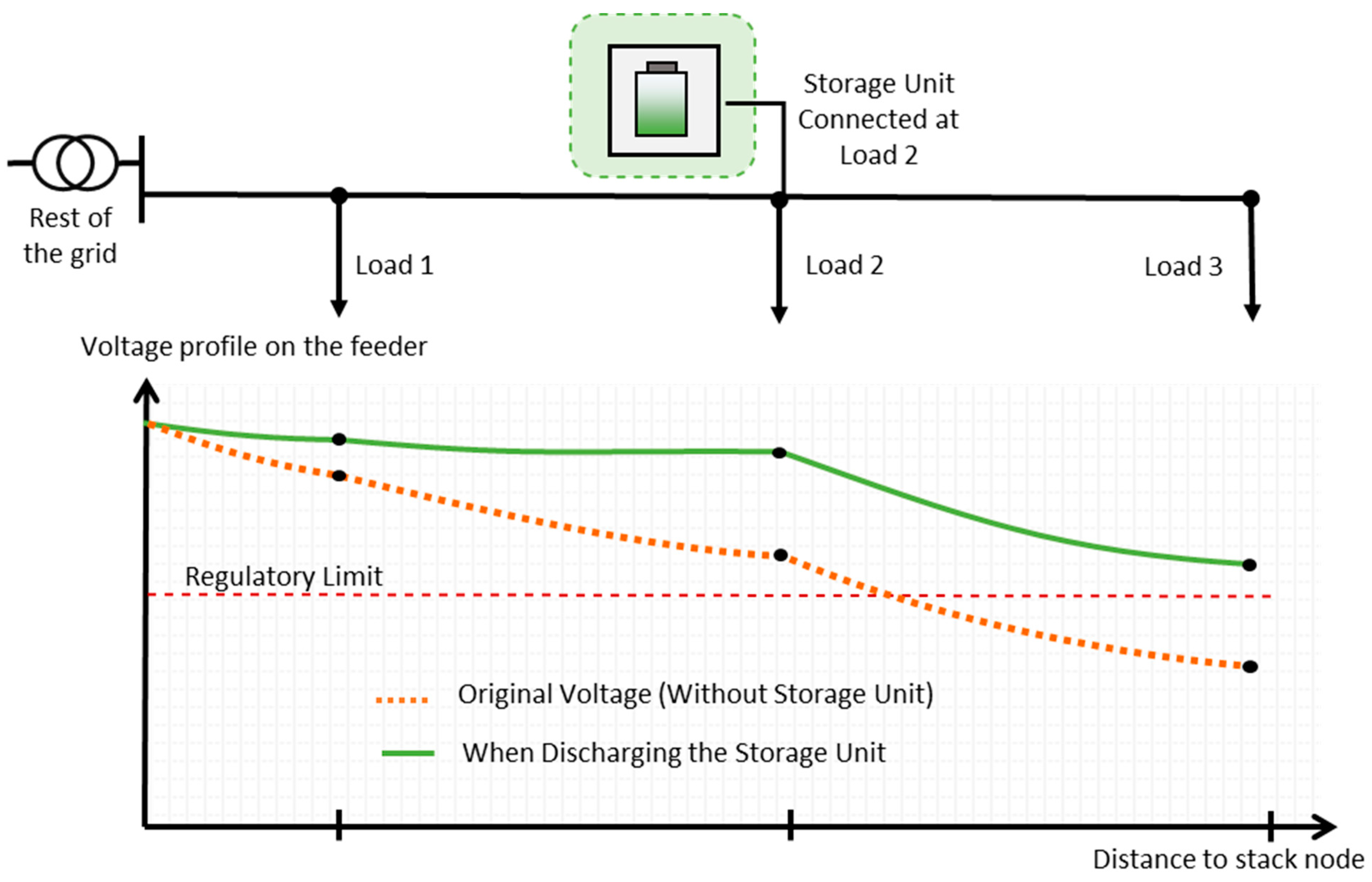
| Voltagesupport | Provide correction to the voltage variations (potentially out of the regulatory values) caused by the resistive and impedance nature of the cables (non-ideal conductors) by injections of active or reactive power. | Using the power converter (STATCOM) to manage reactive power flows and the storage unit to manage the active power flows in order to stabilise voltage close to regulatory values. Figure 4 provides an illustration of this service. | Not necessary. Enable access to more data and thus broaden their positive impact. |
| Power quality | Supporting any electrical parameters which need to remain in a certain range of value during operation, e.g. harmonic level, flickering, power factor, or voltage. | Using the power converter (STATCOM) to manage reactive power flows and compensate harmonics, and voltage or power factor deviations, for instance. | Not needed. |
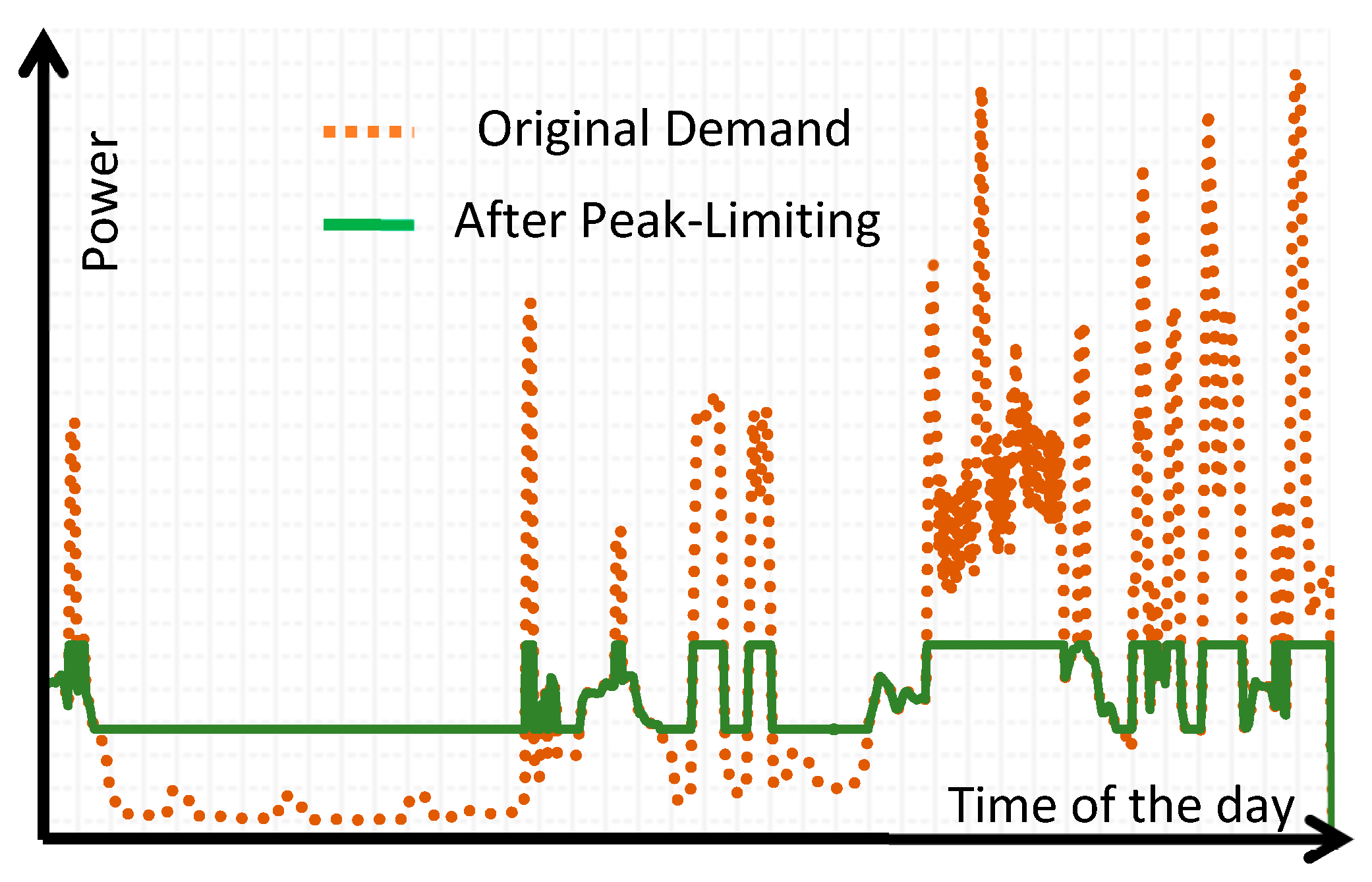
| Peak Limiting | Making up for the demand when it reaches a certain value, so that the power drawn as seen by the grid never overreaches a certain value. Figure 5 illustrates an example of peak shaving | The aggregation of demand profiles which peak has been limited thanks to BtM batteries should result in overall demand with limited peaks. Regardless of the location of storage on the grid, peak limiting only affects upstream components, thus BtM peak limiting should relieve a larger amount of hardware. | Not necessary. Provide coordination between units of a same area leading to overall optimised service. |
| PV Self-consumption | For buildings equipped with rooftop PV panels: Maximising the on-site used energy. | Sensible charging and discharging schedule to maximise the on-site utilisation of the energy produced. | Not necessary. Could help relief stress on grid by coordinating nearby units. |
| Backup provision | Guaranteeing operation of at least some critical appliances in the building for a given time during grid outage. | Keeping a certain amount of energy in the battery and storing energy from PV in case of a grid breakdown. | Not needed. |
| Frequency regulation | Injecting or absorbing power in response to frequency variation in order to maintain it in a between the regulatory limits. | Response to frequency variations by instantaneous injection or absorption of power. | Not necessary, but helpful to make sure this service and others do not interfere with each other. |
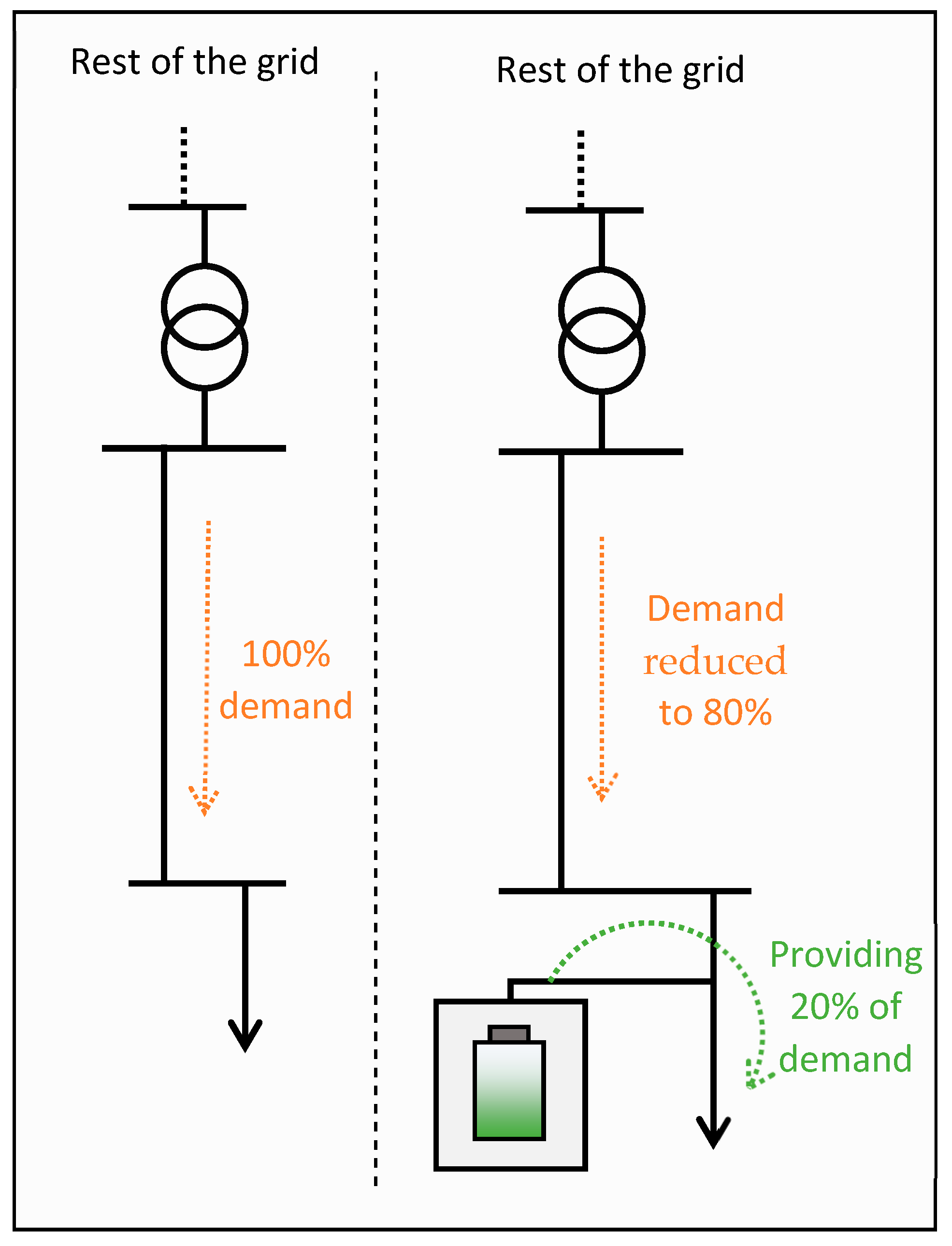
| T&D congestion relief | Downstream a potentially congested line: Charging when the demand downstream is low and discharging to when it increases to diminish the congestion. | Discharging the fleet to cover part of the local demand during peak periods, to decrease the overall energy flowing through the lines. An illustration of this principle for a simple line is found Figure 5. | Necessary to make sure enough energy is stored downstream the congested lines and manage the flows during charging and discharging to keep the line un-congested. |
| Arbitrage and load-levelling | Privileging charging during low demand and discharging during peak times to flatten the overall profile seen by the grid. Resulting in a larger-scale version of what is seen Figure 5. | Charge during low-demand periods and discharge at peak demands. | Necessary to access large-scale demand forecasts. |
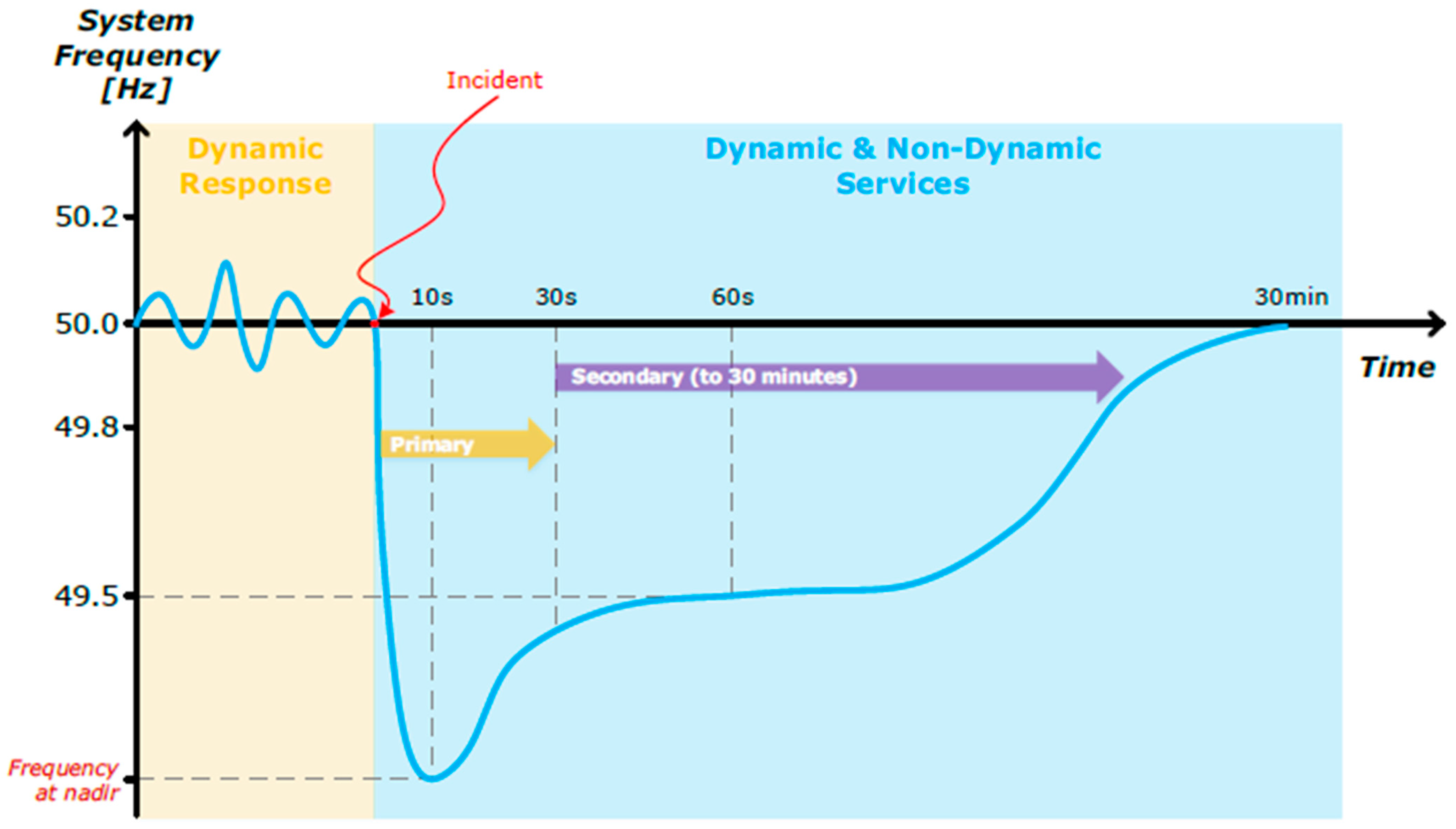
| Reserves | Covering the loss of some generation capacity shortly enough after the event occurs to maintain grid stability. There are different timescales in the response, a generic example is illustrated Figure 6. | Exploiting the potential very short-term response time to quickly respond to unexpected events occurring in the network such as faults or tripping of a generator. | Necessary to relay the information of unexpected events leading to need for reserve dispatch. |
| Load Following | Following the variations of the load profile at a given base-load level. | Adjust an individual unit’s output to reduce the need from load following by fossil fuel-based generators. | Necessary, to adjust a unit’s outputs and ease the effects of overall variations on conventional generator. |
| Renewable Generation Output Smoothing | Making up for short term fluctuations in renewable generation due to weather instabilities (clouds on PV panels or gusts of wind on turbines). | Not achievable by BtM BESS. | - |
| Renewable Generation capacity firming | Firm up renewable’s capacity by guaranteeing a minimum output regardless weather fluctuations and un-forecasted events. | Not achievable by BtM BESS. | - |
| Black-start | In case of grid black out, re-energising the generators to enable their re-connection to the network. | Not achievable by BtM BESS. | - |
| Grid Services | Arbitrage | RG Capacity Firming | RG Capacity Smoothing | Increased Self-Consumption | Congestion Relief | Voltage Support | Power Quality Enhancement | Peak Limiting | Reserves | Frequency Regulation | Load Following | Backup Power | Black-Start | Upgrade Deferral | |
|---|---|---|---|---|---|---|---|---|---|---|---|---|---|---|---|
| Electro-Chemical | PbA | ~ | ✓ | ✓ | ✓ | ~ | ✓ | ✓ | ~ | ~ | ✓ | ✓ | ✓ | ~ | ✓ |
| Li-based | ~ | ✓ | ✓ | ✓ | ~ | ✓ | ✓ | ~ | ~ | ✓ | ✓ | ✓ | ~ | ✓ | |
| Ni-based | ~ | ✓ | ✓ | ✓ | ~ | ✓ | ✓ | ~ | ~ | ✓ | ✓ | ✓ | ~ | ✓ | |
| Flow batteries | ~ | ✓ | ✓ | ✓ | ~ | ~ | ✓ | ~ | ~ | ✓ | ✓ | ✓ | ~ | ✓ | |
| Aggregation of domestic BESS | ✓ | ✕ | ✕ | ✓ | ✓ | ✓ | ✓ | ✓ | ✓ | ✓ | ✓ | ✓ | ✕ | ✓ | |
| Thermal | Sensible Heat | ~ | ✕ | ✕ | ~ | ~ | ✕ | ✕ | ✓ | ✕ | ✕ | ✕ | ✕ | ✕ | ✓ |
| Latent Heat | ~ | ✕ | ✕ | ~ | ~ | ✕ | ✕ | ✓ | ✕ | ✕ | ✕ | ✕ | ✕ | ✓ | |
| Thermochemical | ✓ | ✕ | ✕ | ~ | ~ | ✕ | ✕ | ✓ | ✕ | ✕ | ✕ | ✕ | ✕ | ✓ | |
| Mechanical | Pumped Hydro | ✓ | ✓ | ✓ | ~ | ✓ | ~ | ✕ | ✓ | ✓ | ✓ | ~ | ✕ | ✕ | ✓ |
| Compressed air | ~ | ✓ | ✓ | ~ | ✓ | ~ | ✕ | ✓ | ✓ | ✓ | ~ | ✕ | ✕ | ✓ | |
| Liquid air | ~ | ✓ | ✓ | ~ | ✓ | ~ | ✕ | ✓ | ✓ | ✓ | ~ | ✕ | ✕ | ✓ | |
| flywheels | ✕ | ✕ | ~ | ~ | ✕ | ✕ | ✓ | ~ | ~ | ~ | ✕ | ✕ | ✕ | ~ | |
| Chemical | Hydrogen & others | ✓ | ~ | ~ | ~ | ~ | ~ | ✓ | ~ | ~ | ~ | ~ | ~ | ~ | ✓ |
| Electrical | EDLC | ✕ | ✕ | ~ | ✕ | ✕ | ✕ | ✓ | ✕ | ✕ | ~ | ✕ | ✕ | ✕ | ~ |
| SMES | ✕ | ✕ | ~ | ✕ | ✕ | ✕ | ✓ | ✕ | ✕ | ~ | ✕ | ✕ | ✕ | ~ |
© 2019 by the authors. Licensee MDPI, Basel, Switzerland. This article is an open access article distributed under the terms and conditions of the Creative Commons Attribution (CC BY) license (http://creativecommons.org/licenses/by/4.0/).
Share and Cite
Jankowiak, C.; Zacharopoulos, A.; Brandoni, C.; Keatley, P.; MacArtain, P.; Hewitt, N. The Role of Domestic Integrated Battery Energy Storage Systems for Electricity Network Performance Enhancement. Energies 2019, 12, 3954. https://doi.org/10.3390/en12203954
Jankowiak C, Zacharopoulos A, Brandoni C, Keatley P, MacArtain P, Hewitt N. The Role of Domestic Integrated Battery Energy Storage Systems for Electricity Network Performance Enhancement. Energies. 2019; 12(20):3954. https://doi.org/10.3390/en12203954
Chicago/Turabian StyleJankowiak, Corentin, Aggelos Zacharopoulos, Caterina Brandoni, Patrick Keatley, Paul MacArtain, and Neil Hewitt. 2019. "The Role of Domestic Integrated Battery Energy Storage Systems for Electricity Network Performance Enhancement" Energies 12, no. 20: 3954. https://doi.org/10.3390/en12203954
APA StyleJankowiak, C., Zacharopoulos, A., Brandoni, C., Keatley, P., MacArtain, P., & Hewitt, N. (2019). The Role of Domestic Integrated Battery Energy Storage Systems for Electricity Network Performance Enhancement. Energies, 12(20), 3954. https://doi.org/10.3390/en12203954