Abstract
In this paper, the Routh criterion has been used to analyze the stability of a self-excited induction generator-based isolated system which is regarded as an autonomous system. Special focus has been given to the load capacity of the self-excited induction generator. The state matrix of self-excited induction generators with resistor-inductor load has been established based on transient equivalent circuits in the stator stationary reference-frame. The recursive Routh table of self-excited induction generators is established by the characteristic polynomial coefficients of the state matrix. According to the Routh stability criterion, the necessary and sufficient condition to predict the critical loads of self-excited induction generators is deduced, from which the critical load impedance can be calculated. A simple self-excited induction generator-based isolated power system has been built up with a 2.2 kW self-excited induction generator. The theoretical analysis and experiments were all carried out based on this platform. In the range determined by the minimum excitation capacitance (Cmin) and the maximum excitation capacitance (Cmax), the critical loads under various power factors have been calculated. The agreement of the calculated theoretical results and experimental results demonstrate the effectiveness and accuracy of the proposed analysis method. The conclusions achieved lay a foundation for further application of Routh stability criterion in self-excited induction generator-based power systems analysis.
1. Introduction
Self-excited induction generators have been widely used in renewable energy systems, such as wind power generation [1,2,3,4,5], as well as in isolated power systems, such as ships, aircrafts, and drilling platforms [6,7,8,9], due to their advantages of simplicity, robustness, low-cost, high reliability, no external excitation, and convenient maintenance. With rapid development of renewable and stand-alone energy generation systems, a lot of research has been carried out relating to self-excited induction generators. For instance, the calculation of required capacitance for self-excited induction generators’ self-excitation [10,11], the analysis of various transient processes [12,13,14], and the analysis of self-excited induction generators’ feeding single-phase load [15,16,17].
The main drawback of self-excited induction generators is their inherent poor voltage regulation capability, which is the limiting factor for their wide use [18]. Relevant research has been done on the voltage and frequency control of self-excited induction generators and some achievements have been obtained [19,20,21,22].
In [23], an advanced static synchronous compensator used for the control of self-excited induction generator-feeding random loads was constructed based on the relative rotational speed relationship. The controller was illustrated to eliminate the stator voltage fluctuation due to random load variations and guarantee the effective regulation in generator speed and mechanical power. An isolated self-excited induction generator-static synchronous compensator system feeding dynamic and static loads was analyzed in [24]. The research showed that the proposed system could efficiently provide electric power with either a balanced or unbalanced load. In [25], an improved direct voltage control strategy was proposed for the control of terminal voltage and frequency of a stand-alone wind-driven self-excited induction generator with variable loads. The strategy was verified to have a fast dynamic response and can effectively control the generated voltage with low harmonic distortions under different linear or nonlinear loads.
From the previous research, it can be seen that all the voltage and frequency controls take the load into account. The characteristics of load affect the feasibility and effectiveness of the control strategy.
For self-excited induction generator-based power systems, no matter what voltage control strategy is adopted, there is a corresponding maximum load called the critical load beyond which the control system will not be able to control the voltage, which will collapse as a result. With the development and wider application of self-excited induction generator-based isolated power systems, higher requirements are put forward for its power supply reliability. Therefore, the analysis of the critical load of self-excited induction generators should be paid more attention to for its effect on voltage control. However, until now, there has been almost no literature on the load capacity of self-excited induction generators.
This paper investigates the load capacity of self-excited induction generators. From the definition of autonomous system [26], the self-excited induction generator linearized at the operating point is a linear time-invariant autonomous system. Therefore, the method of analyzing the autonomous system in system control theory can be used in the analysis of self-excited induction generators.
The Routh criterion is a method to determine system stability based on characteristic polynomial coefficients. Its distinct advantage is that it does not need to solve differential equations. Furthermore, the Routh criterion can be used to not only determine system stability but also check the stability margin. As an effective method in stability analysis, the Routh criterion has been used in various engineering systems [27,28,29,30]. In this paper, based on the transient equivalent circuits, the Routh criterion is used to analyze the load capacity of self-excited induction generators.
In a self-excited induction generator-based isolated power system, the excitation part can use the excitation capacitor or electronic equipment such as Static Var Compensators or a Static Synchronous Compensator. The function of electronic equipment is more powerful and effective. However, in many applications where reliability or cost is a major concern, the capacitor bank is widely used. The capacitor bank has a simple structure and is easy to use, low-cost, and robust which avoids complex controls and potential reliability issues of electronics devices, so they are preferred in a range of applications as in ships, drilling platforms, and renewable applications. The focus of this paper is on the feasibility of using the Routh criterion to analyze the self-excited induction generator-based isolated power system. As such, the excitation capacitor is chosen to provide the reactive current for the system.
The main contribution of this paper is the establishment of the model of self-excited induction generators for stability analysis using the Routh criterion. The feasibility of applying the Routh criterion to stability analysis of self-excited induction generators is verified by the analysis of load capacity. All the work lays a foundation for further application of the Routh stability criterion in analysis of self-excited induction generators.
This paper is organized as follows: Firstly, a simple self-excited induction generator-based isolated power system is built. The state matrix of self-excited induction generators is derived from its transient equivalent circuits (Section 2). Secondly, a brief description of how to construct a recursive Routh table is introduced. Then according to the characteristics of the system with critical load, the Routh criterion for calculating critical load is obtained (Section 3). Thirdly, the Routh criterion is used to predict the critical load of the self-excited induction generator (Section 4). Finally, experiments are carried out on the given system to validate the calculations and verify the correctness of the analysis (Section 5). The experimental results demonstrate the feasibility of employing the Routh criterion to analyze the behavior of self-excited induction generators, and the conclusions are presented in Section 6.
2. Transient Modeling of Self-Excited Induction Generator-Based Isolated Power Systems
Figure 1 shows a simple self-excited induction generator-based isolated power system. The system has been built up with a 2.2 kW, Y connection, 380 V, 5 A, 50 Hz, and 4 poles self-excited induction generator which is driven by a DC motor model zft132. Both theoretical analysis and experiments are carried out on the basis of this system.

Figure 1.
The self-excited induction generator-based isolated power system.
Figure 2 is the schematic of the system shown in Figure 1. Three-phase capacitor banks with a Y connection provide reactive current to assist with initiating voltage build-up and maintaining the terminal voltage of the self-excited induction generator with load. The capacitors are usually called excitation capacitors. The three-phase inductors and resistors (L and R) in Figure 2 are loads.

Figure 2.
Schematic diagram of the isolated self-excited induction generator system.
The analysis of the self-excited induction generator with load is based on the transient equivalent circuit. The mutual inductance between stator and rotor is time-varying in Cartesian coordinates, due to the fact that it is a function of rotor speed. Therefore, the Clarke transform is applied to eliminate the time variation of mutual inductance in transient analysis. After the transformation, the mutual inductance is time independent. A control-oriented linearized model accounting for the dynamic cross-saturation effect is given in [23] which is more accurate than a simple model that assumes the mutual inductance to be constant. However, at the self-excitation boundary, the mutual inductance M is located at the critical point of the linear region and the saturation region, the simplified model and the model accounting for the dynamic cross-saturation tend to be consistent here. The objective of this paper is to predict the load capacity of self-excited induction generators, i.e., the analysis in this paper is carried out on the self-excitation boundary of the self-excited induction generator. Therefore, the simplified model is adopted in this paper. Figure 3 shows the stator stationary reference-frame α-β axis transient equivalent circuits of a self-excited induction generator with load.

Figure 3.
Transient equivalent circuits of self-excited induction generators.
In Figure 3, Rs and Ls are the stator resistance and leakage inductance, respectively, and are the referred values of rotor resistance and rotor leakage inductance, and are the referred rotor-side flux linkages, M is the mutual inductance, C is excitation capacitance, and ω is the rotor speed. isα and isβ are the stator currents, and are the referred values of the rotor currents, usα and usβ are the excitation capacitance voltages, and iLα and iLβ are the load currents, respectively. R is the load resistance and L is load inductance. The positive direction of the variables is also shown in Figure 3.
The electromagnetic state equations of the self-excited induction generator can be obtained based on Figure 3 using Kirchhoff’s laws [31]: (1) shows the stator voltage equations, (2) shows the rotor voltage equations, and (3) is the rotor flux equation.
Substituting (3) into (2) to eliminate the rotor flux, the voltage equations of stator and rotor are arranged as (4).
In (4), Lms = Ls + M is the stator inductance and = + M is the referred rotor inductance.
The current and voltage equations of the excitation capacitance can be given as:
While those of the load are:
Define a state vector:
, the state matrix of the self-excited induction generator can be obtained from (4) to (6), the detailed form of which is shown in Appendix A, and can be written concisely as:
Therefore, the characteristic polynomial of the state matrix A is:
I is an identity matrix with the same order as the state matrix.
3. The Routh Criterion for Predicting Self-Excited Induction Generator Load Capacity
The first step in applying the Routh criterion is to write the Routh table according to the coefficients of the characteristic polynomial. The characteristic polynomial of the self-excited induction generator-based isolated power system is an eight-order equation. Since this is a high-order system, the recursive Routh table is used to reduce the complexity and workload, shown in Table 1.

Table 1.
Recursive Routh table of the self-excited induction generator-based isolated power system.
Each row starting from the third one is computed from its two preceding rows as:
Here i is the row number, which goes from 1 to 9, and j is the column number, which goes from 1 to 5.
When computing the last element of certain row of the recursive Routh table, one may find that the preceding row is one element short of what is needed. For example, when is computed, is needed, but is not an element of the recursive Routh table. In that case, the preceding row can be simply augmented by a zero in the end to keep the computation going.
According to the Routh stability criterion, the necessary and sufficient condition for the stability of linear systems is that the elements of the first column in the recursive Routh table are all positive, otherwise the system is unstable [32].
In system theory, stability refers to whether the system can recover to the original equilibrium state with certain accuracy after the disturbance disappears [33]. If the disturbance disappears and the system can gradually return to its original equilibrium state, then the system is stable, otherwise the system is unstable.
The normal power generation operating mode of self-excited induction generators is a critically stable state where its output voltage is sinusoidal with constant amplitude.
From the analysis, it can be concluded that when self-excited induction generators supply power normally, with respect to the Routh criterion, the first column of the recursive Routh table, that is (n = 0, 1…, 8) in Table I, should have at least one element less than zero. As the load increases, when its impedance reaches a certain value, the system is in a critical state between instability and stability. Beyond this working point, the load exceeds the load capacity of the self-excited induction generator, that is to say the load impedance is less than the critical one, elements of the column are all positive, and the output voltage of the self-excited induction generator decreases to zero rapidly. The system collapses and returns to its initial stable state. The load impedance at which the system is in a critical state between instability and stability, in other words, (n = 0, 1…, 8) in Table I changes from being not all positive to completely positive, is the maximum load the self-excited induction generator can carry.
According to the characteristics of self-excited induction generator parameters, it is obvious that a0, a1, and a8, which are the first, second, and ninth row of the recursive Routh table’s first column, are always positive. The proof process is as follows.
Therefore, the condition to estimate the critical load is simplified to determine the point at which the elements from to in the recursive Routh table’s first column change to be completely positive.
When the self-excited induction generator parameters are given, the elements of the recursive Routh table are only affected by the excitation capacitance, the rotor speed, and the load. Keeping the excitation capacitance and rotor speed constant, the critical load can be found through the state change of the system. The load impedance increases from a small value until any of , , , , , or changes from positive to negative. The load impedance at that state is the critical load of the self-excited induction generator.
4. Theoretical Calculation
The parameters of the self-excited induction generator used in this paper are listed in Table 2.
Table 2.
Parameters of the self-excited induction generator.
The mutual inductance M, which corresponds to the magnetizing current of the induction generator im through the no-load magnetization curve, is obtained from a synchronous no-load experiment. The magnetizing current of the induction generator im is the sum of the stator current and the rotor current. The amplitude of im is as follows:
When im is small, the self-excited induction generator operates in the unsaturated flux region and M is constant. When im is larger than a certain value, the self-excited induction generator operates in the saturated region. In the saturated region, M decreases rapidly with the increase of im.
During the dynamic simulation and the analysis of the self-excited induction generator, a piece wise function which is shown by (13) is used to express the relationship between M and im. In this paper, as mentioned in Section 2, the analysis is carried out on the self-excitation boundary of the self-excited induction generator. Therefore, the unsaturated value M = 0.3754 which can only be used for self-excitation boundary conditions computation is adopted in the subsequent computation.
The resistance of the rotor is affected by temperature, speed, and other factors. Especially, the increase of temperature in the operation process will cause an increase of . It can be calculated that effect of rotor resistance variation on critical load is not obvious. Thus, the variation of the rotor resistance is not taken into account.
Inserting the prototype parameters into equation (7) with rotor speed n = 1500 r/min, excitation capacitance C = 35 μF, and power factor (PF) = 0.8, the characteristic polynomial of the self-excited induction generator can be obtained. Substituting the coefficients of the characteristic polynomial into Table 1, the recursive Routh table is calculated with load impedance starting from zero. Nine elements in the first column are all positive until the load impedance is increased to 259 Ω. The calculated results are shown in Table 3.
Table 3.
The first column of the recursive Routh table with n = 1500 r/min, C = 35 μF, and power factor (PF) = 0.8.
When Z is equal to 259 Ω, the eighth element turns from positive to negative. According to the Routh criterion for the load capacity of self-excited induction generators, the critical load of this prototype under the above operating conditions is 259 Ω.
In the same manner, under the conditions that n = 1500 r/min, C = 37 μF, and PF = 0.7, the critical load impedance was found to be 241 Ω, as shown in Table 4.
Table 4.
The first column of recursive Routh table with n = 1500 r/min, C = 37 μF, PF = 0.7.
Using the method mentioned above, when n maintains a constant value 1500 r/min, variations of the critical load impedance with the excitation capacitance under a certain PF can be calculated. As is known, for a specific rotor speed, there are critical excitation capacitance values Cmin and Cmax, and between them the self-excitation is stable. Two self-excitation boundaries related to Cmin and Cmax respectively can be obtained. The relationship between the critical load impedance and the excitation capacitance when PF = 0.8 is shown as an example. Because Cmax and Cmin differ by about two orders of magnitude, the two boundaries are shown in Figure 4 and Figure 5 respectively for clearer display.

Figure 4.
The lower boundary of critical load varying with excitation capacitances at PF = 0.8.

Figure 5.
The upper boundary of critical load varying with excitation capacitances at PF = 0.8.
From Figure 4 and Figure 5, it can be concluded that there exists a minimum critical load impedance corresponding to the excitation capacitance when the excitation capacitance is in the range between Cmin and Cmax. With the increase of excitation capacitance, the critical load impedance reduces. In other words, the load carrying capacity is enhanced. However, the load capacity will decrease when the excitation capacitance is too large approaching the Cmax.
The relationship curves between the critical load impedance and the excitation capacitance under various PF values when n = 1500 r/min are shown in Figure 6 and Figure 7.

Figure 6.
The lower boundary of critical load varying with excitation capacitances at a different PF.

Figure 7.
The upper boundary of critical load varying with excitation capacitances at a different PF.
From Figure 6 and Figure 7, it can be concluded that in order to maintain the power generation of the self-excited induction generator, the excitation capacitance must be situated in the range between Cmin and Cmax. For a specific PF, when the excitation capacitance is larger than Cmin and much less than Cmax (as shown in Figure 6), increasing the excitation capacitance tends to make the critical load impedance decrease and the load capacity improve. By keeping the excitation capacitance constant, with the increase of the PF, the critical load impedance decreases. However, when the excitation capacitance increases too much approaching the Cmax, all the trends are reversed (as shown in Figure 7). The increase of the excitation capacitance will make the critical load impedance increase. For a certain excitation capacitance, with the increase of the PF, the critical load impedance increases too.
In Figure 6, as the excitation capacitance decreases, the curves corresponding to different PFs all tend to the same value, below which the self-excited induction generator cannot operate with any load. This minimum excitation capacitance can be proved to be the no-load voltage build-up excitation capacitance of the generator. Similar trends can be observed in Figure 7, all curves move towards the maximum excitation capacitance of the no-load build-up voltage when the excitation capacitance increases.
5. Experimental Results
In order to verify the correctness of the method proposed in this paper, the results calculated above are tested on the platform shown in Figure 1.
Data acquisition was carried out by a Synergy series 16-channel recorder (SynergyP16H). The sampling rate of the recorder was 200 kS/s per channel. The recorder adopted an automatic tracking anti-aliasing filter (Gauss FS/8) with a filtering cut-off frequency of 25 kHz. A SINAMICS DCM (6RA80) was adopted in the timing part.
Figure 8 shows the comparison between theoretical results with experimental results when self-excited induction generator was fed resistance load. Experiments were carried out when load impedance was set to 100 Ω, 200 Ω, 400 Ω, and 500 Ω respectively.

Figure 8.
Critical load varying with excitation capacitances at PF = 1.
When the self-excited induction generator was fed resistance-inductance load, for there were only 500 mH, 100 mH, and 200 mH reactors available to be used in the test, several groups of experiments were arranged as follows.
5.1. Case 1, n = 1500 r/min, load PF = 0.8
According to the existing load inductor, the load impedance was set to 261.7 Ω (L = 500 mH, R = 209 Ω). From the calculation method proposed in Part 4, the excitation capacitance corresponding to the critical load 261.7 Ω was 34.9 μF. Due to losses during the experiment consuming energy, the actual excitation capacitance should be slightly greater than 34.9 μF. In this experiment, the initial value of excitation capacitance was set to 35.5 μF. Figure 9 shows the voltage and current waveforms of phase A respectively.
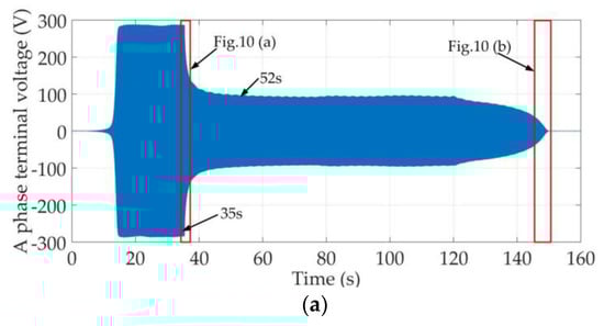

Figure 9.
Stator voltage and current waveform of phase A in case 1: (a) Voltage waveform; (b) Current waveform.
After the rotor speed of the self-excited induction generator settled at 1500 r/min, at about 5 s, a bank of three-phase excitation capacitors were engaged, and the self-excited induction generator started the voltage build-up process. This process finished at about 15 s, at which point the no-load stator terminal voltage remained at about 290 V. At about 35 s, a bank of three-phase balanced resistive-inductive loads with impedance of 261.7 Ω and PF = 0.8 were connected. The stator terminal voltage decreased rapidly and at about 52 s and the stator terminal voltage dropped to 100 V. Then, at 120 s, excitation capacitances were reduced from 35.5 μF to 35.4 μF, simultaneously, the voltage collapsed and eventually dropped to zero.
The whole experimentation lasted for more than 150 s. In order to observe the variation trend of waveforms more clearly, two segments of waveform marked in the boxes in Figure 9a are zoomed in, which are shown in Figure 10a,b.

Figure 10.
(a) The waveform from 35 s to 38 s; (b) The waveform from 145 s to 150 s.
From this experiment, the error between calculated value and actual value can be estimated. When the critical load is 261.7 Ω and PF = 0.8, the corresponding theoretical boundary value of the excitation capacitance is 34.9 μF, and the actual experimental value is 35.5 μF. The absolute error here is 0.6 μF, and the relative error is only 1.7%. The accuracy of the method is verified.
5.2. Case 2, n = 1500 r/min, C = 37 μF, PF = 0.7
The critical load impedance in this condition was calculated to be 241 Ω. Two different loads, where one is slightly larger and another was smaller than the critical load, were fed to the self-excited induction generator respectively. The experimental waveforms are shown in Figure 11 and Figure 12.

Figure 11.
Stator voltage and current waveform of phase A when load is within the self-excited induction generator’s load capacity: (a) Voltage waveform; (b) Current waveform; (c) Voltage waveform from 51 s to 57 s.

Figure 12.
Stator voltage and current waveform of phase A when load exceeds the self-excited induction generator’s load capacity: (a) Voltage waveform; (b) Current waveform; (c) Voltage waveform from 31 s to 39 s.
From Figure 11a, at 8 s, excitation capacitors were connected, and the no-load voltage build-up process finished at 15 s with C = 37 μF. The stator terminal voltage of the self-excited induction generator remained at about 300 V. At about 51 s, a bank of three-phase balanced resistive-inductive loads with 263.9 Ω impedance (L = 600 mH, R = 184.7 Ω) were connected. As this load impedance was greater than the critical load (within the permitted load range), the stator terminal voltage decreased to 146 V and then remained at this value. Figure 11b is the stator current waveform of phase A. Figure 11c is the close-up view of the waveforms in the boxes in Figure 11a.
In Figure 12a, the voltage build-up process is the same as Figure 11a. The no-load voltage build-up process finished at 15 s and the stator terminal voltage was about 300 V. At about 32 s, resistive-inductive loads with 219.9 Ω impedance (L = 500 mH, R = 153.9 Ω) were added. As this load impedance was lower than the critical one, the self-excited induction generator could not carry it, and the voltage collapsed and eventually dropped to zero. Figure 12b is the stator current waveform of phase A. Figure 12c is the close-up waveforms in the boxes in Figure 12a.
From the experimental results, it can be seen that when the load exceeds the critical load and the load impedance is smaller than the critical load, the stator terminal voltage collapses to zero. When the load impedance is greater than the critical load, after a short transient process, the terminal voltage drops to a lower value and the self-excited induction generator continues operating steadily. These experimental results verify the accuracy of the proposed stability analysis method.
6. Conclusions
The main results obtained from the research are as follows:
- The self-excited induction generator-based isolated power system is regarded as a linear non-time-varying autonomous system at its operating point on the self-excited boundary. The Routh criterion is applied to analyze the stability of this system.
- The load capacity of the self-excited induction generator which is expressed by critical load is considered as the analysis object. By the recursive Routh table, the critical load value of the self-excited induction generator is predicted. The self-excited induction generator can maintain output voltage when its load impedance value is greater than the critical one, otherwise, the output voltage of the self-excited induction generator will collapse to zero.
- The critical load impedance value decreases with the increase of the excitation capacitance. For a certain excitation capacitance, the larger the load power factor, the smaller the critical load impedance.
- Experiments verified the effectiveness and accuracy of the proposed method. The error between calculated theoretical value and experimental value is caused by losses in experiments.
Regarding future work, for stand-alone self-excited induction generator power systems, the change of rotor speed should be taken into account in its stability analysis. The model proposed in [23] will be a good choice when using the Routh criterion to analyze the whole stable operation region of self-excited induction generators in the next step.
Author Contributions
J.L. conceived and designed the study. She was also responsible for the theoretical calculations and experiments. This work was performed under the advisement and regular feedback from X.W., X.Y. and H.W.
Funding
This research was funded by National Natural Science Foundation of China, grant number: 51677092. The APC wad funded by National Natural Science Foundation of China.
Conflicts of Interest
The authors declare no conflict of interest.
Appendix A
The autonomous system state matrix of the self-excited induction generator:
In which
References
- El-Khattam, W.; Sidhu, T.S.; Seethapathy, R. Evaluation of Two Anti-Islanding Schemes for a Radial Distribution System Equipped with Self-Excited Induction Generator Wind Turbines. IEEE Trans. Energy Convers. 2010, 25, 107–117. [Google Scholar] [CrossRef]
- Murthy, S.S.; Singh, B.; Sandeep, V. Design-based computational procedure for performance prediction and analysis of single-phase self-excited induction generator. IET Electr. Power Appl. 2013, 7, 477–486. [Google Scholar] [CrossRef]
- Huang, P.H.; Moursi, M.S.E.; Xiao, W.; Kirtley, J.L. Fault Ride-Through Configuration and Transient Management Scheme forSelf-Excited Induction Generator-Based Wind Turbine. IEEE Trans. Sustain. Energy 2013, 5, 148–159. [Google Scholar] [CrossRef]
- Thomsen, B.; Guerrero, J.M.; Thøgersen, P.B. Faroe Islands Wind-Powered Space Heating Microgrid Using Self-Excited 220-kW Induction Generator. IEEE Trans. Sustain. Energy 2014, 5, 1361–1366. [Google Scholar] [CrossRef]
- Abbou, A.; Akhrif, R.E. Experimental DSPACE analysis of three phase SEIG used in wind turbine. In Proceedings of the 2016 International Renewable and Sustainable Energy Conference (IRSEC), Marrakech, Morocco, 14–17 November 2016; pp. 414–419. [Google Scholar]
- Singh, B.; Murthy, S.S.; Chilipi, R.R.; Madishetti, S.; Bhuvaneswari, G. Static synchronous compensator-variable frequency drive for voltage and frequency control of small-hydro driven self-excited induction generators system. IET Gener. Transm. Distrib. 2014, 8, 1528–1538. [Google Scholar] [CrossRef]
- Senthil Kumar, S.; Kumaresan, N.; Subbiah, M. Analysis and control of capacitor-excited induction generators connected to a micro-grid through power electronic converters. IET Gener. Transm. Distrib. 2015, 9, 911–920. [Google Scholar] [CrossRef]
- Tischer, C.B.; Tibola, J.R.; Scherer, L.G.; de Camargo, R.F. Proportional-resonant control applied on voltage regulation of standalone SEIG for micro-hydro power generation. IET Renew. Power Gener. 2017, 11, 593–602. [Google Scholar] [CrossRef]
- Chermiti, D.; Khedher, A. Two reliable approaches to determine the critical excitation capacitor value for a SEIG operating in stand-alone. In Proceedings of the International Conference on Green Energy Conversion Systems, Hammamet, Tunisia, 23–25 March 2017; pp. 1–6. [Google Scholar]
- Wu, X.Z.; Wang, X.H. Self-excited capacitance of induction generator for no-load operation. J. Tsinghua Univ. 2004, 44, 893–896. [Google Scholar]
- Mahato, S.N.; Singh, S.P.; Sharma, M.P. Excitation capacitance required for self-excited single phase induction generator using three phase machine. Energy Convers. Manag. 2008, 49, 1126–1133. [Google Scholar] [CrossRef]
- Kim, C.K.; Choy, Y.D.; Lim, S.J. Transient Simulation of a Self-Excited Induction Generator during Grid Faults. J. Power Electron. 2007, 7, 89–96. [Google Scholar]
- Singh, B.; Singh, M.; Tandon, A.K. Transient Performance of Series-Compensated Three-Phase Self-Excited Induction Generator Feeding Dynamic Loads. IEEE Trans. Ind. Appl. 2010, 46, 1271–1280. [Google Scholar] [CrossRef]
- Abu-Elhaija, W.S.; Muetze, A. Self-Excitation and Stability at Speed Transients of Self-Excited Single-Phase Reluctance Generators. IEEE Trans. Sustain. Energy 2013, 4, 136–144. [Google Scholar] [CrossRef]
- Wang, Y.J.; Lee, M.H. A Method for Balancing a Single-Phase Loaded Three-Phase Induction Generator. Energies 2012, 5, 3534–3549. [Google Scholar] [CrossRef]
- Singh, B.; Murthy, S.S.; Chilipi, R.S.R. STATCOM-Based Controller for a Three-Phase SEIG Feeding Single-Phase Loads. IEEE Trans. Energy Convers. 2014, 29, 320–331. [Google Scholar]
- Kalla, U.K.; Singh, B.; Murthy, S.S. Adaptive noise suppression filter based integrated voltage and frequency controller for two-winding single-phase self-excited induction generator. IET Renew. Power Gener. 2014, 8, 827–837. [Google Scholar] [CrossRef]
- Bansal, R.C. Three-phase self-excited induction generators: An overview. IEEE Trans. Energy Convers. 2005, 20, 292–299. [Google Scholar] [CrossRef]
- Singh, B.; Murthy, S.S.; Reddy, R.S.; Arora, P. Implementation of modified current synchronous detection method for voltage control of self-excited induction generator. Power Electron. IET 2015, 8, 1146–1155. [Google Scholar] [CrossRef]
- Kiselychnyk, O.; Bodson, M.; Wang, J. Linearized State-Space Model of a Self-Excited Induction Generator Suitable for the Design of Voltage Controllers. IEEE Trans. Energy Convers. 2015, 30, 1310–1320. [Google Scholar] [CrossRef]
- Enany, M.A. Terminal voltage control of a standalone SEIG using Genetic Algorithm optimized ANFIS controller. In Proceedings of the 2016 Eighteenth International Middle East Power Systems Conference, Cairo, Egypt, 27–29 December 2016; pp. 407–412. [Google Scholar]
- Giri, A.K.; Arya, S.R.; Maurya, R.; Babu, B.C. Power Quality Improvement in Stand-alone SEIG based Distributed Generation System using Lorentzian Norm Adaptive Filter. IEEE Trans. Ind. Appl. 2018, 54, 5256–5266. [Google Scholar] [CrossRef]
- Chen, W.L.; Lin, Y.H.; Gau, H.S.; Yu, C.H. STATCOM Controls for a Self-Excited Induction Generator Feeding Random Loads. IEEE Trans. Power Deliv. 2008, 23, 2207–2215. [Google Scholar] [CrossRef]
- Singh, B.; Murthy, S.S.; Gupta, S. A Stand-Alone Generating System Using Self-Excited Induction Generators in the Extraction of Petroleum Products. IEEE Trans. Ind. Appl. 2010, 46, 94–101. [Google Scholar] [CrossRef]
- Geng, H.; Xu, D.; Wu, B.; Huang, W. Direct Voltage Control for a Stand-Alone Wind-Driven Self-Excited Induction Generator with Improved Power Quality. IEEE Trans. Power Electron. 2011, 26, 2358–2368. [Google Scholar] [CrossRef]
- Zheng, D.Z. Linear System Theory; Tsinghua University Press: Beijing, China, 2002. [Google Scholar]
- Zhang, Z.C.; Zhang, Y.; Zhang, J.S.; Wu, Z.G. Routh Criterion Hofp bifurcation and its application to electric power systems. Relay 2005, 33, 34–41. [Google Scholar]
- Cespedes, M.; Sun, J. Adaptive control of grid-connected inverters based on online grid impedance measurements. IEEE Trans. Sustain. Energy 2014, 5, 516–523. [Google Scholar] [CrossRef]
- Charroyer, L.; Chiello, O.; Sinou, J.J. Parametric study of the mode coupling instability for a simple system with planar or rectilinear friction. J. Sound Vib. 2016, 384, 94–112. [Google Scholar] [CrossRef]
- Sambariya, D.K.; Rajawat, A.S. Application of Routh stability array method to reduce MIMO SMIB power system. In Proceedings of the IEEE 6th International Conference on Power Systems, New Delhi, India, 4–6 March 2016. [Google Scholar]
- Krause, P.C.; Wasynczuk, O.; Sudhoff, S.D. Analysis of Electric Machinery and Drive Systems; IEEE Press: New York, NY, USA, 2002. [Google Scholar]
- Hu, S.S. Principle of Automatic Control, 5th ed.; Science Press: Beijing, China, 2007. [Google Scholar]
- Khalil, H.K. Nonlinear Systems, 3rd ed.; Prentice-Hall: Upper Saddle River, NJ, USA, 2002. [Google Scholar]
© 2019 by the authors. Licensee MDPI, Basel, Switzerland. This article is an open access article distributed under the terms and conditions of the Creative Commons Attribution (CC BY) license (http://creativecommons.org/licenses/by/4.0/).