Article

Applying Virtual Inertia Control Topology to SMES System for Frequency Stability Improvement of Low-Inertia Microgrids Driven by High Renewables

1
Department of Electrical and Electronic Engineering, Kyushu Institute of Technology, 1-1, Sensui-cho, Tobata-ku, Kitakyushu-shi, Fukuoka 804-8550, Japan
2
Department of Mechanical Engineering, Suranaree University of Technology, 111, Maha Witthayalai Rd., Mueang Nakhon Ratchasima District, Nakhon Ratchasima 30000, Thailand
*
Author to whom correspondence should be addressed.
Energies 2019, 12(20), 3902; https://doi.org/10.3390/en12203902
Submission received: 4 September 2019 / Revised: 9 October 2019 / Accepted: 10 October 2019 / Published: 15 October 2019

Abstract

:
To integrate renewable energy into microgrids with a favorable inertia property, a virtual inertia control application is needed. Considering the inertia emulation capabilities, insufficient emulation of inertia power due to the lower and short-term power of storage systems could significantly cause system instability and failure. To enhance such capability, this paper applies a virtual inertia control topology to the superconducting magnetic energy storage (SMES) technology. The SMES-based virtual inertia control system is implemented in a microgrid with renewables to emulate sufficient inertia power and maintain good system frequency stability. The efficacy and control performance of the proposed control method are compared with those of the traditional virtual inertia control system. Simulation results show that the shortage of system inertia due to renewable penetration is properly compensated by the proposed control method, improving system frequency stability and maintaining the robustness of system operations.

1. Introduction

Frequency stability is significant in the stable and safe operation of power systems, reflecting the fundamental position of power systems in generation and demand. An imbalance could lead to continual deviation of the system frequency. Nowadays, small-scale power systems known as microgrids are quickly developed due to their main advantages, such as simple integration of distributed renewable energy sources (RESs), feasibility, and resiliency in power system operation. The utilization of RESs would result in critical consequences for the safety operations of microgrids. The bulk replacement of conventional generations (based on synchronous generators) by RESs could create new stability threats to the systems, resulting in the degradation of system performance and stability. Firstly, RESs-based generations are connected to the microgrids via power electronic interfaces (converters/inverters), which could not generate the inertia property, resulting in a significant reduction of the whole system inertia. The inertia property plays a significant task in slowing down the frequency deviations during a disturbance, which could help in controlling system frequency stability and damping; thus, the frequency deviation and oscillatory will be critically affected [1]. An excessive frequency deviation may occur, resulting in undesirable load-shedding, cascading outages, or even wide-area power blackouts. Secondly, the rate of change of frequency (ROCOF) of microgrids is significantly increased due to high RESs integration. High ROCOF exposure makes the generation units prone to pole-slipping, resulting in protective tripping [2].
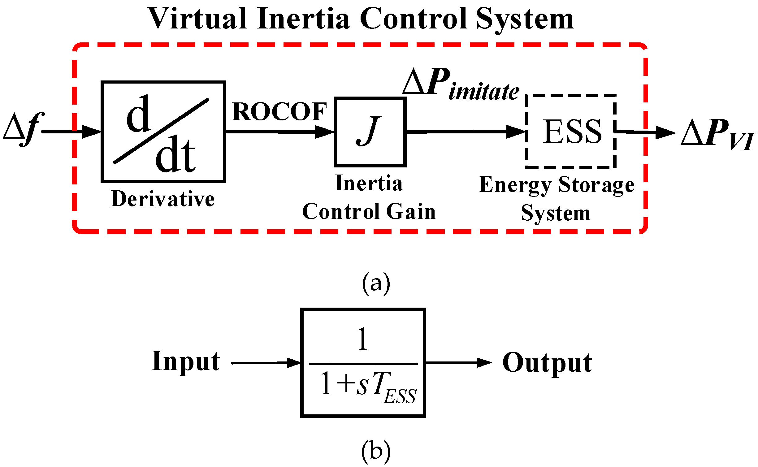
To overcome these new stability threats, one straightforward solution is the development of auxiliary control, usually named virtual inertia control or virtual synchronous generator (VSG), which imitates the behavior of actual synchronous generators without using prime movers or rotating mass, tackling stability issues [1,2,3,4,5,6]. Such control system could be established with an energy storage system (ESS) and inverter. Consequently, the additional inertia power could be virtually imitated to the microgrid during RESs penetration, enhancing system inertia, frequency stability, and resiliency. Previous research achievements on virtual inertia control and its application are discussed in References [7,8], including literature reviews. In [9,10], it was verified that virtual inertia control applications could effectively offer uninterrupted power transfer to the grid-connected and isolated modes during the RESs penetration, enhancing overall microgrid stability and resiliency.
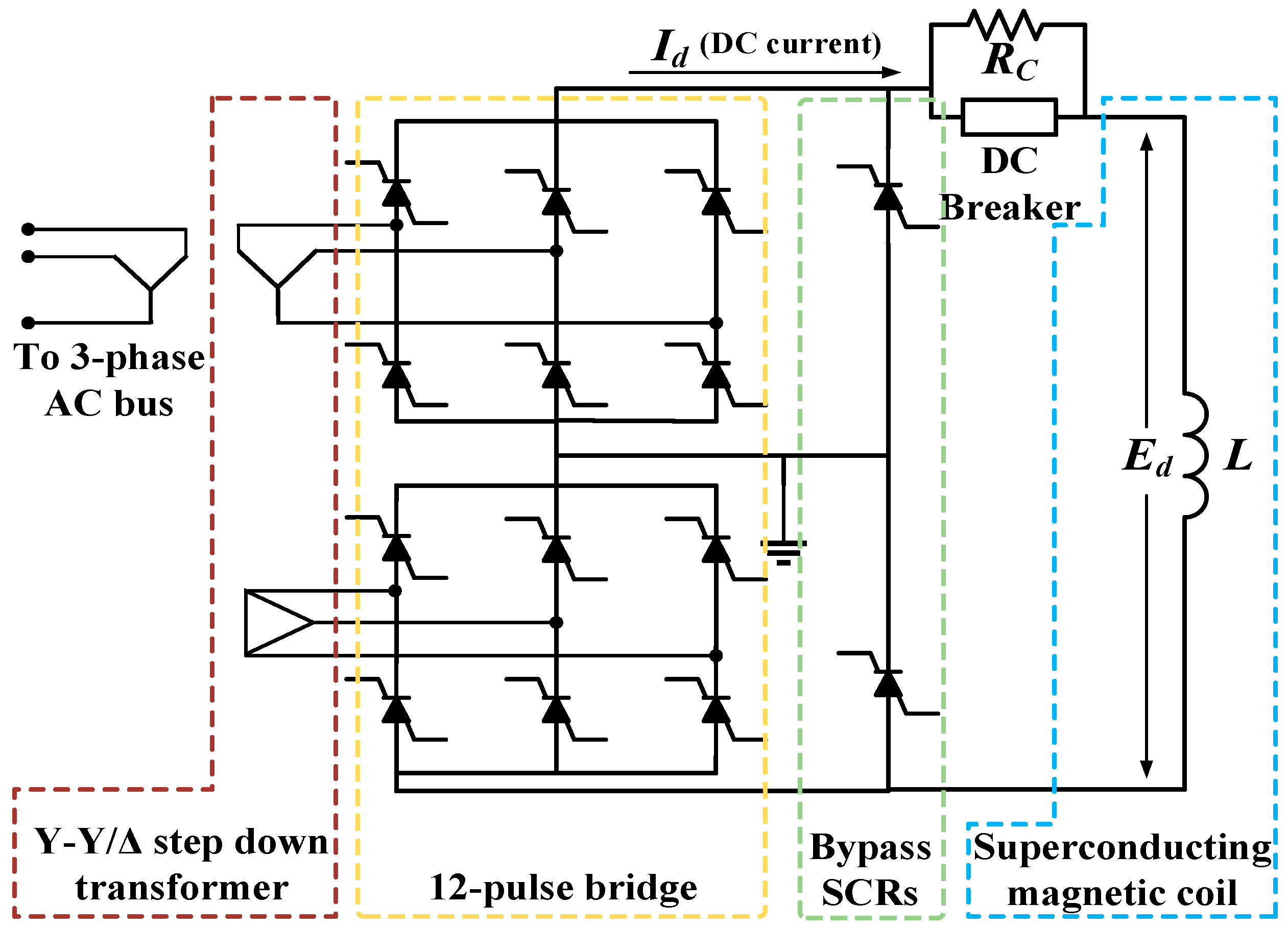
To maintain stable and robust inertia emulation/control capabilities, the microgrid relies inevitably on stabilizing devices (i.e., ESS). The ESS devices may not deliver enough power for a short period of time, leading to insufficient inertia power. This effect can cause system instability, cascading outages, and partial or complete power blackouts. Moreover, the high RESs penetration in microgrids might have adverse effects on the virtual inertia control performance and stability. Considering such drawbacks, the superconducting magnetic energy storage (SMES) technology is among ESS choices due to its major advantages of fast response, high efficiency, high energy/power, and unlimited number of charging/discharging cycles [11,12]. The main advantage of SMES is that it can discharge large amounts of power in a short period of time. Especially, to react to the sudden changes in microgrid dynamics, an active power source with fast-response capability such as a SMES unit is expected to be the most effective countermeasure. The feasibility of SMES for enhancing power system dynamic problems (voltage/frequency stability) has been reported [11,13,14,15,16]. Various works [17,18,19,20] further used the SMES for power system transient stability improvement. Based on a literature survey in regard to SMES technology, there were no conclusive studies on the utilization of virtual inertia control topology using SMES technology for microgrid frequency enhancement.
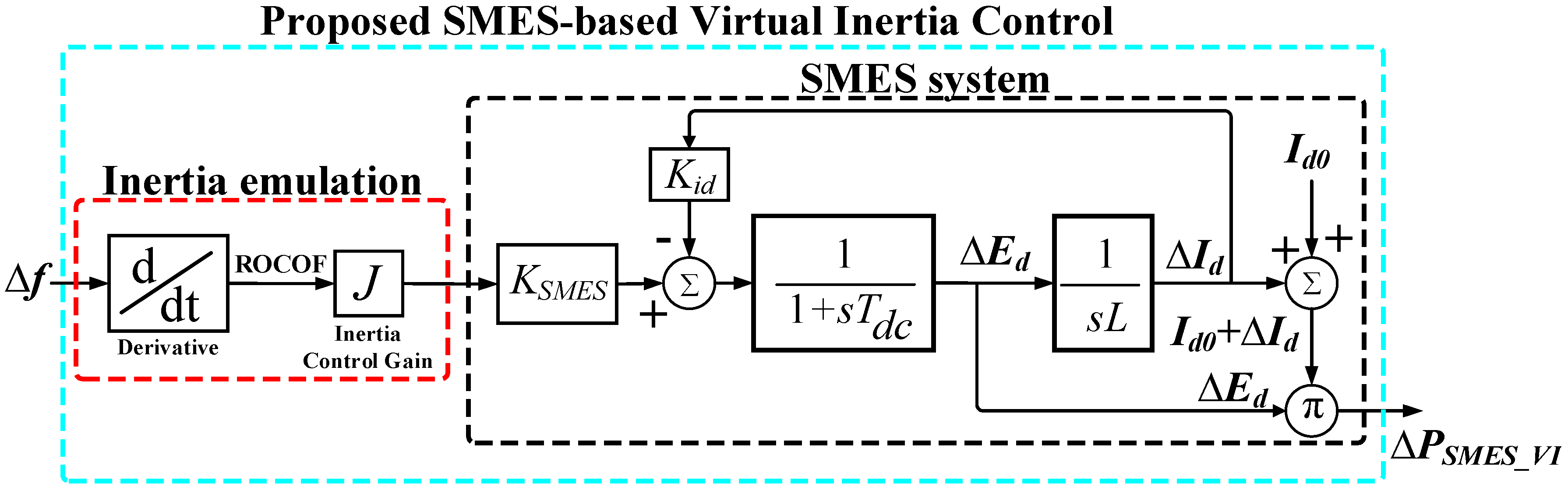
In an attempt to address the aforementioned limitations, this is the first study proposing the coordinated design of virtual inertia control topology based on SMES technology to improve microgrid stability and resiliency. The SMES-based virtual inertia control system is implemented in the studied microgrid with RESs to emulate sufficient inertia power and maintain robust system frequency stability, avoiding system instability, cascading outages, and wide-area power blackouts. The simulation studies were performed under a MATLAB/Simulink® 2019 environment. To evaluate the efficacy and robustness of the proposed control method, the obtained results were compared with conventional ESS-based virtual inertia control in References [2,3,4,5,6,21].
The main contributions of this paper over the existing virtual inertia control techniques are as follows: (1) this is the first paper that proposes an explicit model of the SMES system that can capture the key dynamic characteristics of virtual inertia control topology for enhancing inertia emulation capability, improving frequency stability, and resiliency of the microgrid; (2) the dynamic effects of the proposed SMES-based virtual inertia control are analyzed and validated by the time domain simulation, evaluating a new trade-off between inertia response/emulation and short-term ESS power in regard to frequency stability improvement; (3) compared with the conventional ESS-based virtual inertia control in References [2,3,4,5,6,21], the proposed control strategy shows remarkable performance and stability in terms of high energy/power and fast response, resulting in the lowest frequency deviation and transient excursion. Thus, the lower and short-term power from the ESS could be solved, avoiding system instability, cascading outages, and wide-area power blackouts.
The organization of this paper is as follows. 
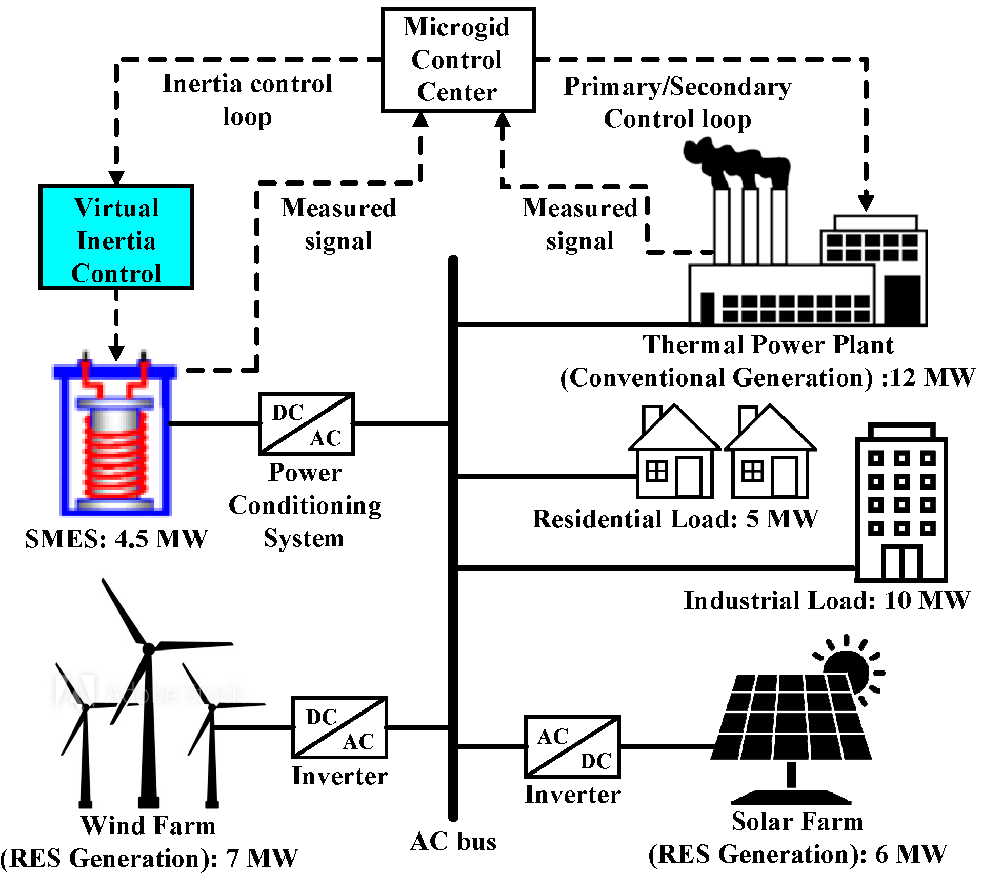
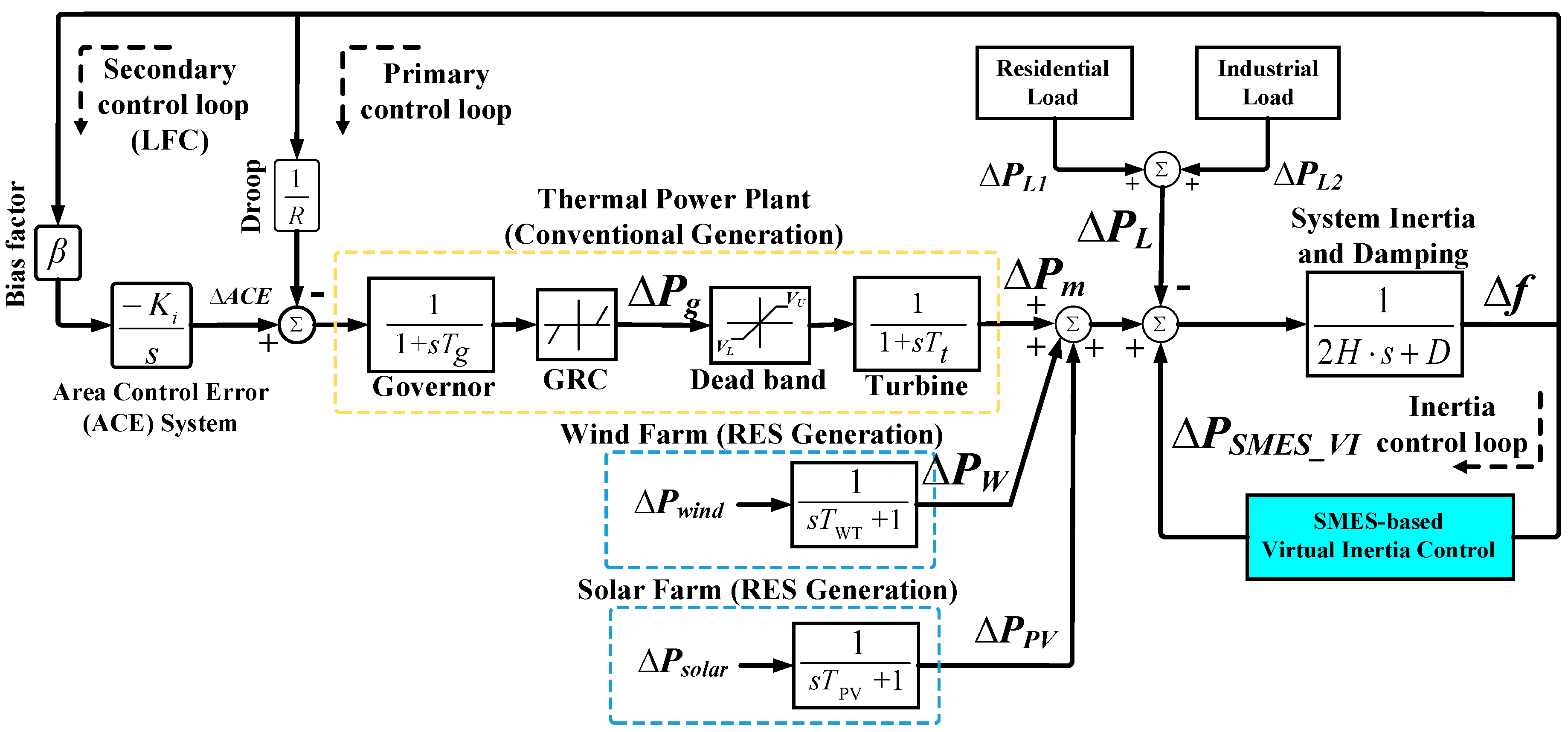
Section 2 demonstrates the system overview including microgrid modeling for a frequency stability study. 
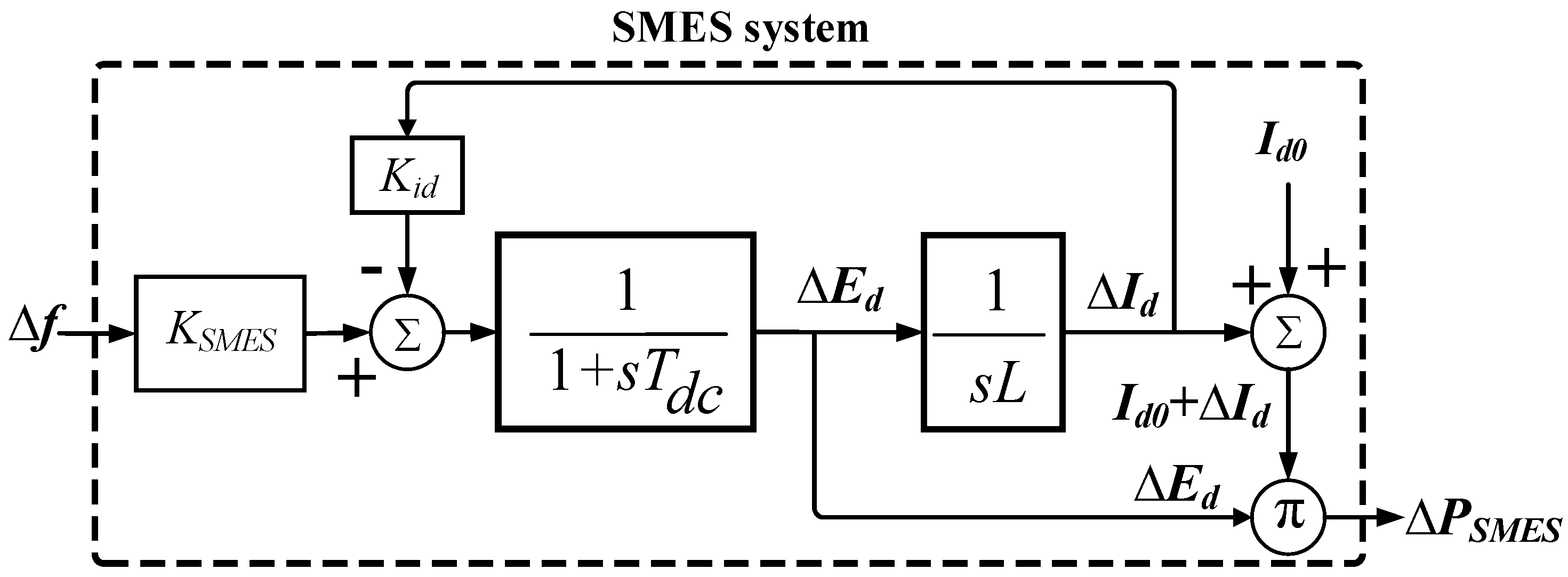
Section 3 proposes the control scheme of SMES-based virtual inertia control for frequency stability enhancement. Section 4 describes the simulation results and analysis based on the time-domain. Section 5 provides some conclusions in regard to this work.

2. Study System and Modeling

2.1. Fundamental of Inertia Power Based on Frequency Stability Control

Frequency regulation/stability is a balance between generation and load demand. If there is an excess of generation or demand, the system (microgrid) frequency will increase or decrease, respectively. The imbalance could cause the continual deviation of system frequency. Accordingly, the well-known swing equation of a generator, which describes the dynamics of generation-load power imbalance in terms of frequency deviation and inertia power is expressed as follows [1,2,5,22,23]:
Δ P m c Δ P L = 2 H d Δ f d t + D Δ f
where ∆PL is the load power change, ∆Pmc is the mechanical power change, H is the inertia constant of the system, D is the load damping coefficient, and ∆f is the deviation of system frequency.
When inertia power and/or damping of the system decrease, the frequency deviation and ROCOF are increased. In microgrids, the value of D is likely small, while H is primarily varying based on the number of synchronous generation units. Hence, the relationship between the inertia constant of the system and the inertia constant of the synchronous generator could be calculated as follows [1,2,5,22]:
H = i ( H S G i   S S G i ) / S M G
where SMG is the total microgrid power, and SSG is the rated power of the synchronous generator. Thus, when the integration of RESs increases, the system inertia essentially decreases.

2.2. Modeling of Microgrid for Frequency Stability Study

The studied system consists of a solar farm, wind farm, thermal power station, SMES unit, and industrial/residential loads as shown in Figure 1. The power cable (solid line) is used for exchanging the electrical power demand, and the communication system (dash line) is used for exchanging system status and control information. The system base is 15 MW. The SMES unit is implemented to the microgrid to emulate inertia power during the integration of solar/wind farms, improving system frequency stability and resiliency. The thermal power station provides primary/secondary frequency control [2,4]. To demonstrate the actual system operation, the solar/wind farms (RESs) are not controlled to generate power into the system. The capability of such RESs generation depends on the wind speed and solar irradiation. Thus, they could not participate in system frequency control. Accordingly, we consider the RESs power generation and load power consumption as the disturbances to the system. To create the drastic system condition, the studied microgrid is not connected to any large power grid, serving as the stand-alone mode.
To perform the frequency response study, the dynamic model of the microgrid considering the dynamic effects of RESs generation-load was constructed as Figure 2. The significant inherent requirement and constraints (e.g., generation rate constraint (GRC) and governor dead-band imposed by physical system dynamics) were applied in this study based on Reference [5]. Based on References [1,2,3,4,5,6,13,14,21,22,24,25], the dynamic model (depicted in Figure 2) is sufficient for frequency stability study and analysis. The main simulation parameters for the studied microgrid are given in Table 1 [5,14]. Accordingly, the frequency deviation of the microgrid is determined as
Δ f = 1 2 H s + D ( Δ P m + Δ P W + Δ P P V + Δ P S M E S _ V I Δ P L )
where
Δ P m = 1 1 + s T t Δ P g
Δ P g = 1 1 + s T g ( A C E 1 R Δ f )
A C E = K i β Δ f s
Δ P W = 1 1 + s T W T Δ P w i n d
Δ P P V = 1 1 + s T P V Δ P s o l a r
Here, ∆Pm is the active power change from the conventional unit, ∆Pg is the governor valve position change, ACE is the secondary control action/signal change, ∆PW is the active power change from the wind farm unit, ∆PPV is the active power change from the solar farm unit, ∆PL is the total load change caused by residential/industrial loads, and ∆PSMES_VI is the virtual inertia power change from the SMES unit, which will be described in the following section.

3. Design of SMES-Based Virtual Inertia Control for Frequency Stability Enhancement

3.1. Overview of Studied SMES

The schematic diagram depicted in Figure 3 displays the basic configuration of the thyristor-controlled SMES used in this study. The studied SMES system consists of a superconducting magnetic inductor/coil, AC/DC thyristor-controlled bridge converter, and Wye-Delta transformer. The power conditioning system (PCS) including the rectifier/inverter manages the power transfer between the AC bus/system and magnetic coil. To diminish the harmonics generated on the output voltage to the coil and AC bus, a 12-pulse converter is applied [13,14]. The converter generates negative or positive voltage on the magnetic coil. The discharge and charge are simply regulated by changing the firing angle (α), which controls the thyristor sequential firing [11,13,14]. If α is lower than 90°, the converter is charging (rectifier mode). If α is higher than 90°, the converter is discharging (inverter mode). In the steady state, the SMES is not consumed any active/reactive power. Thus, the power could be released or absorbed to the microgrid as required. The relationship between the DC voltage of the converter and the firing angle is expressed as follows [13,14,24]:
E d = 2 V d 0 cos α 2 I d R C
where Ed is the DC voltage at the inductor, Vd0 is the maximum circuit bridge voltage, Id is the current flowing via the inductor, and RC is the equivalent commutating resistance.
To conduct the frequency response analysis, in the dynamic model of the SMES, presented in Figure 4 [13,14,26], the SMES is controlled based on the deviation of system frequency (Δf) as the input signal to generate the required power (ΔPSMES) to the system. Thus, the SMES inductor/coil voltage (Ed) is proportionally controlled using Δf to the SMES control logic. Based on References [13,14], the inductor current must be recovered to its nominal value rapidly after the contingency/disturbance so that it can instantly respond to the next contingency. Therefore, the negative feedback signal (Kid) is applied to the SMES system.
The dynamic equations of inductor voltage deviation (ΔEd) and inductor current deviation (ΔId) are expressed as follows [13,14,26]:
Δ E d = K S M E S 1 + s T D C Δ f K i d Δ I d
where
Δ I d = 1 s L Δ E d
Here, KSMES is the control gain for SMES loop, Kid is the feedback gain for ΔId, TDC is the converter time constant of SMES, L is the induction coil, and Id0 is the inductor rated current of SMES.
Therefore, the active power deviation of the SMES system can be determined as
Δ P S M E S = Δ E d ( I d 0 + Δ I d )

3.2. Modeling of SMES for Virtual Inertia Control

The concept of virtual inertia control in regard to system frequency regulation, which is based on the derivative method, is presented in Figure 5a [2,3,4,5,6]. If the derivative of system frequency is proportionally used for modifying the active power reference of a converter/inverter, the inertia power could be imitated into the system, enhancing the inertia response of the system against the contingencies/disturbances. The general equation for the active power of the converter/inverter (Pimitate) can be expressed as [4]
Δ P i m i t a t e = J ( d ( Δ f ) d t )
where J is the virtual inertia control constant.
To emulate the virtual inertia power (ΔPVI) in the system, additional devices, such as the ESS are required [1,2,3,4,5,6]. Several types of ESS technologies can be applied for this control application. The dynamic model of the ESS-based inverter is shown in Figure 5b. Due to the major advantages of fast response, i.e., high efficiency and high power, this work proposes the novel design of SMES-based virtual inertia control to enhance microgrid frequency performance and resiliency during contingencies. In this work, the time constant of the ESS (TESS) was 10 s. The ESS/SMES power capacity limit was ±0.3 p.u.
The control scheme shown in Figure 6 is proposed to imitate sufficient inertia power using the SMES. The derivative control technique (df/dt) is applied to calculate the ROCOF to add the required active power to the set-point of the microgrid during the contingencies. Consequently, the active power produced by the SMES is proportionally controlled based on the change of system frequency. Hence, the virtual inertia power could be virtually imitated by the SMES, which contributes to improving the whole system inertia, system frequency, and performance against the RESs integration. The dynamic equation for emulating inertia power using the SMES (ΔPSMES_VI) in regards to system frequency deviation can be defined as
Δ P S M E S _ V I = J 1 + s T D C ( K S M E S d ( Δ f ) d t K i d Δ I d ) ( I d 0 + Δ I d )

4. Simulation Results and Discussion

To validate the robustness and efficacy of the proposed control technique, nonlinear simulations are established under the MATLAB®/Simulink® environment. Two contrastive severe scenarios with different integration levels of wind/solar farms, industrial/residential load patterns, and control parameters were performed for investigating microgrid frequency response. The results of the proposed SMES approach were compared with traditional ESS-based virtual inertia control presented in References [2,3,4,5,6,21]. To comply with the frequency operating standards (grid codes) of actual power systems (Nordic and AEMC) [27], the acceptable ranges of frequency deviation used in this work are applied as ±1 Hz during the generation/load event, and as ±0.5 Hz during no contingency.

4.1. Stability Assessment under High Inertia Microgrid (Low RESs Penetration)

This scenario examines the microgrid frequency stability under the normal operating condition. In 
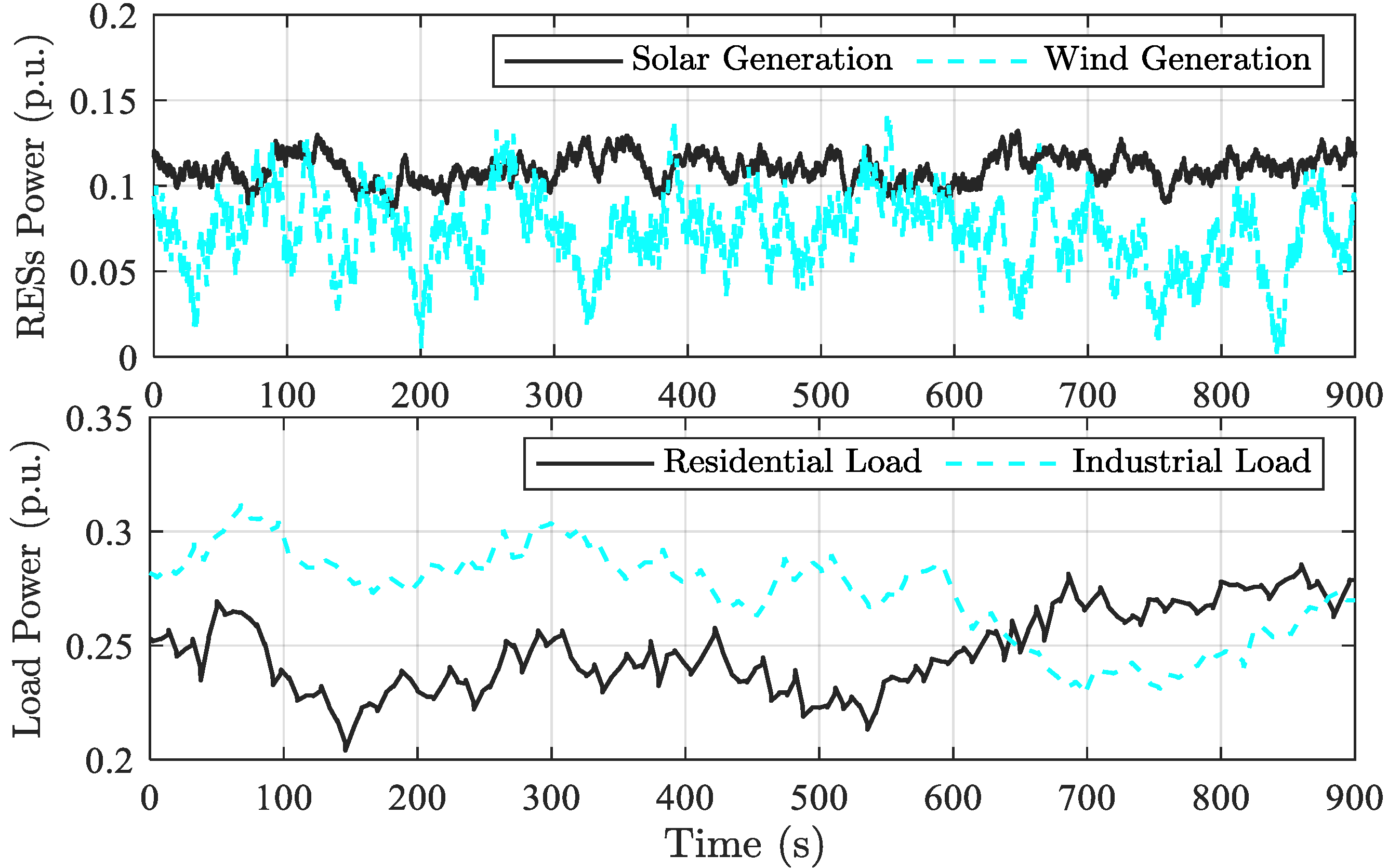
Figure 7, the industrial and residential loads are operated at its heavy loading condition, resulting in high load damping. The RESs (wind and solar systems) are lightly penetrated into the microgrid, resulting in high system inertia (10% reduction from its nominal value).
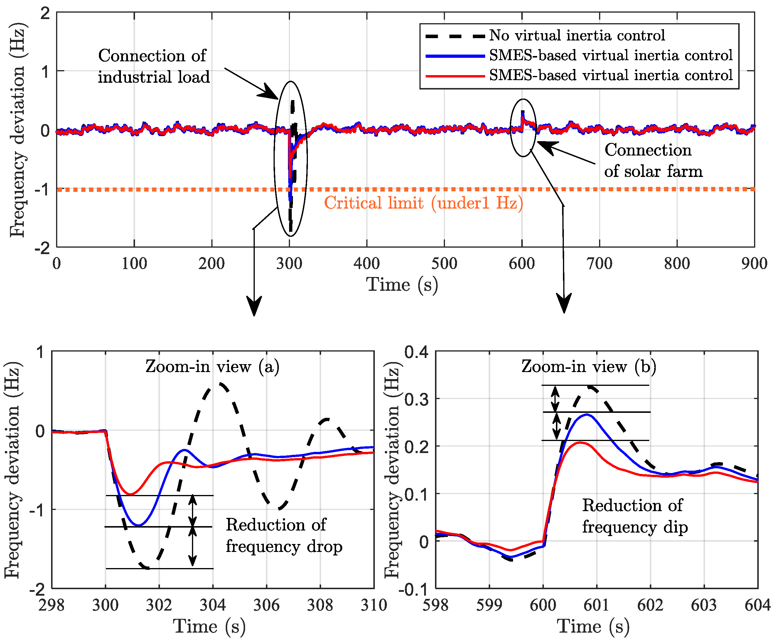
Figure 8 shows the microgrid frequency response under the normal operating condition (high system inertia). In cases of no virtual inertia control and traditional ESS-based virtual inertia control, there are large frequency drops of −1.8 Hz and −1.2 Hz, respectively, during the sudden integration of the industrial load (at 300 s). The amplitudes of the frequency drop exceed the allowable grid code limit (±1 Hz or ±100 mHz), causing deregulated microgrid stability. On the contrary, the proposed SMES-based virtual inertia control could properly compensate the sudden change, resulting in a lower frequency drop of −0.85 Hz. The proposed control method is able to suppress the oscillation quickly and maintain the frequency stability within the allowable grid codes. During the increasing penetration of solar farms (renewable energy) started from 600 s, there is a larger frequency rise (dip) of +0.32 Hz in the case of no virtual inertia control, and +0.28 Hz in the case of traditional ESS-based virtual inertia control. Obviously, the proposed SMES-based virtual inertia control could significantly enhance the performance of the ROCOF, resulting in the lowest frequency rise. The frequency rise is effectively suppressed by the proposed control with the lowest value of +0.19 Hz. Nevertheless, traditional ESS-based virtual inertia control yields a longer stabilizing time during the sudden changes in frequency (drop and dip) compared with the proposed control method. This scenario validates the efficacy of the proposed control method in regulating stable and reliable microgrid operation.
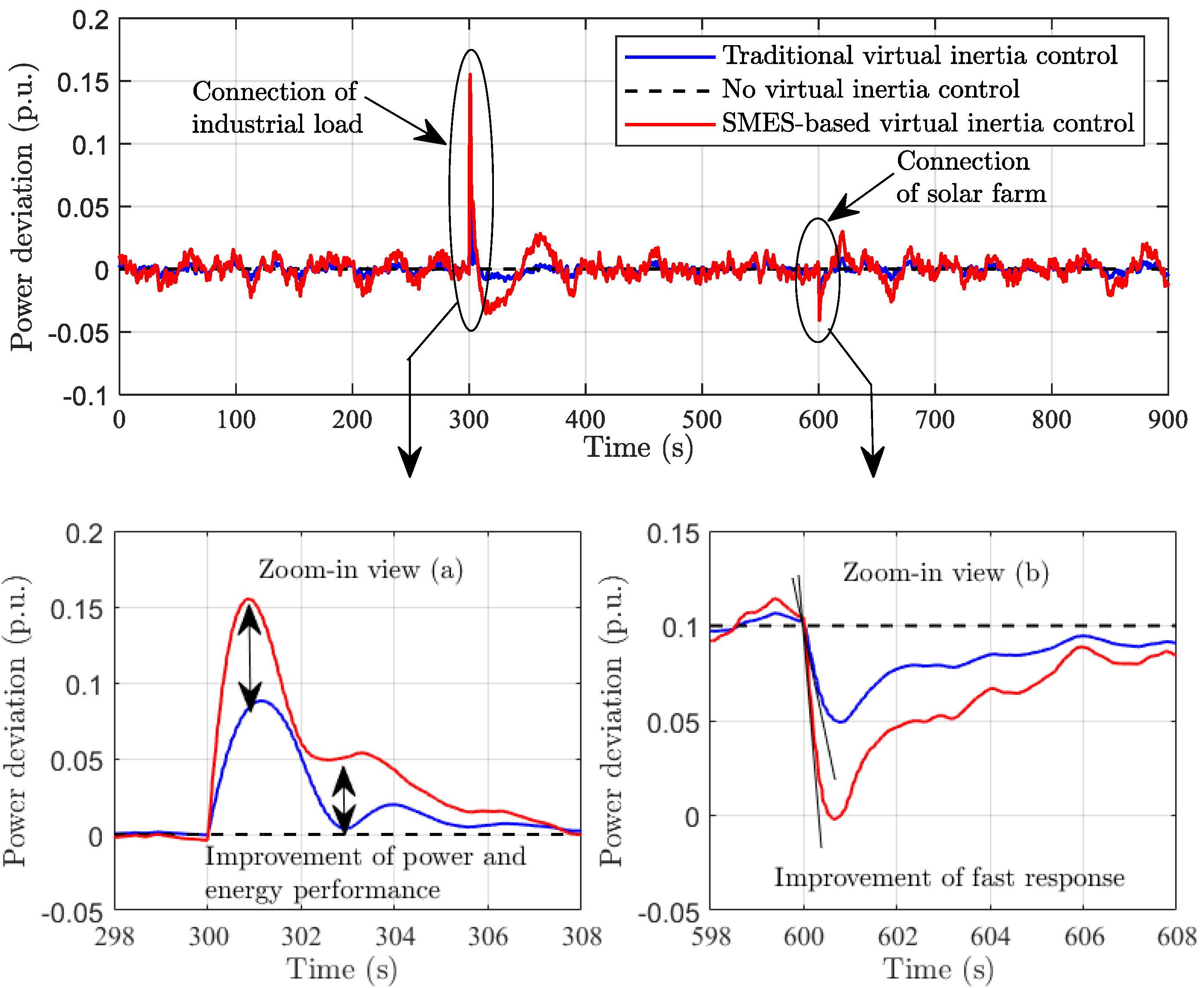
It is obvious that the transient performance of the system significantly improved in terms of peak deviation (dip/drop) and settling time in the presence of the SMES system. Figure 9 illustrates that the SMES-based virtual inertia control can extract more inertia power by discharging than does traditional ESS-based virtual inertia control. Hence, the thermal unit (conventional generation) requires less power generation owing to the proposed control method.

4.2. Stability Assessment under Low Inertia Microgrid (High RESs Penetration)

This scenario examines the microgrid frequency stability under the severe operating condition. The robustness of the proposed control method is also investigated with utmost penetration of renewable energy and huge reduction of total system inertia. In 
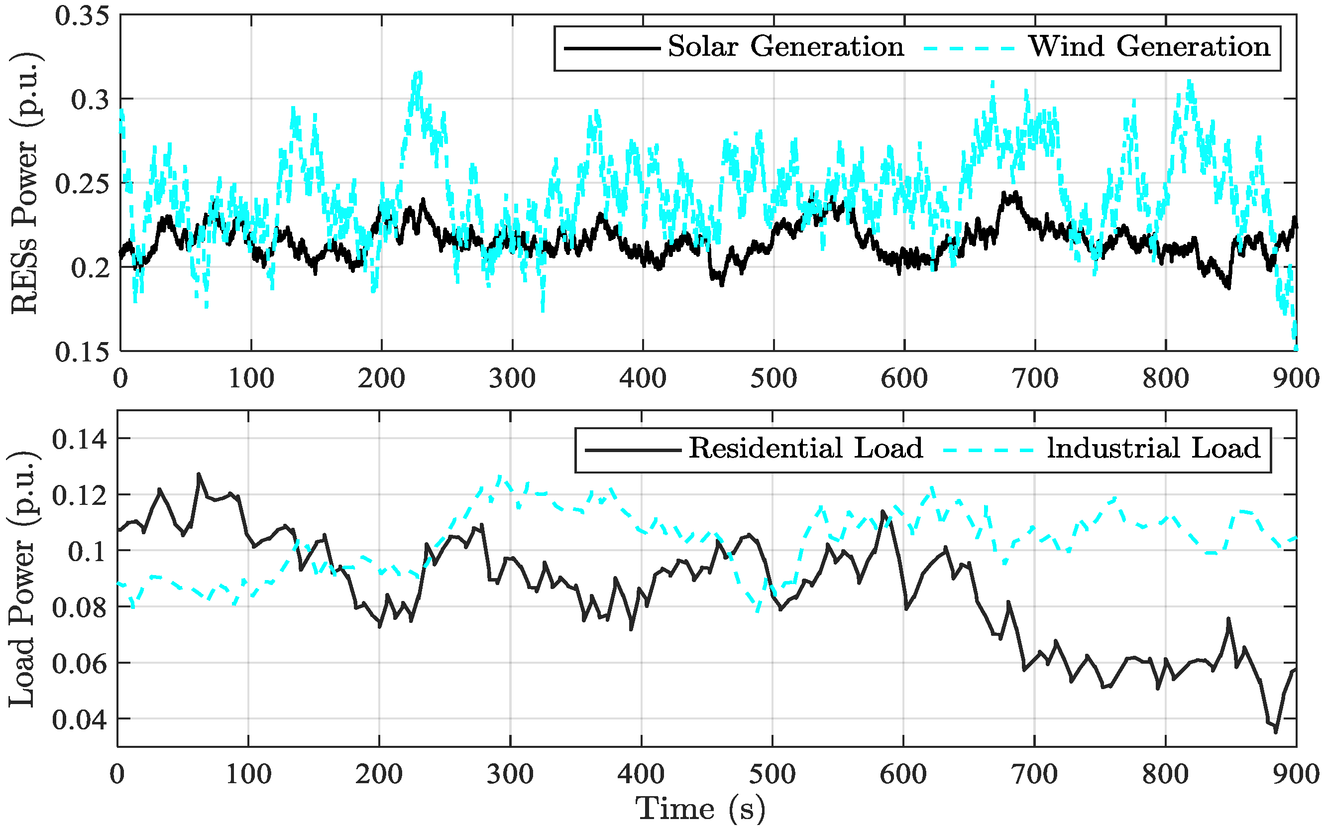
Figure 10, the wind and solar systems are highly penetrated into the microgrid, creating a huge reduction in system inertia (70% decrease from its nominal value). To conduct a more critical scenario, the industrial and residential loads are lightly operated at their partial demand, resulting in the critical condition of low load damping (50% decrease from its nominal value).
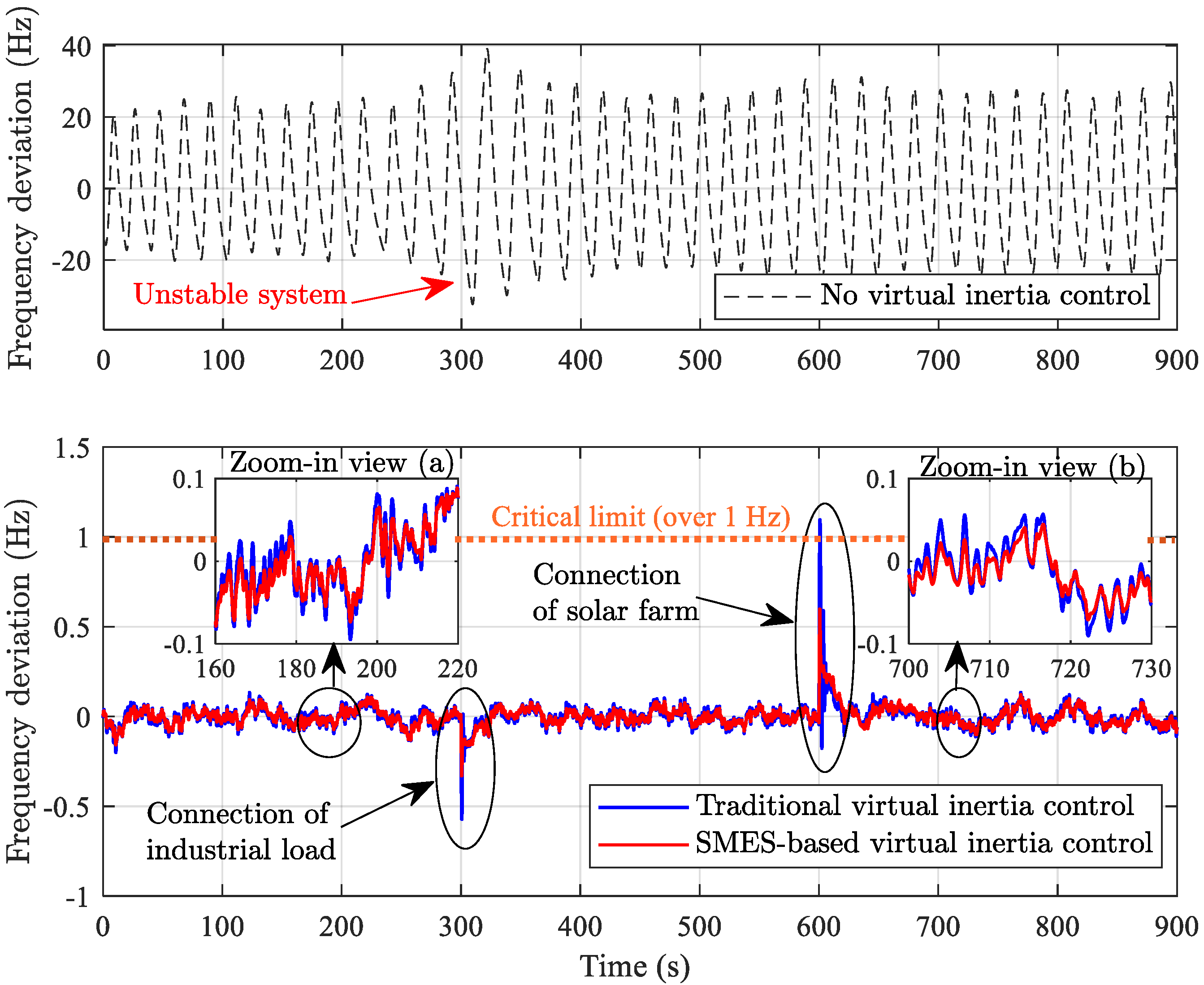
Figure 11 shows the microgrid frequency stability under the critical situation of low system inertia. Due to the huge reduction of system inertia driven by high renewable integration, the performance of ROCOF is critically deteriorated, resulting in higher ROCOF. Subsequently, the deviation of system frequency in all scenarios significantly increases. In the case of no virtual inertia control, the system frequency extremely fluctuates and loses the stabilizing effect due to the utmost renewable integration, resulting in an unstable system and wide-area power blackout. Clearly, the SMES-based virtual inertia control can robustly damp the frequency deviation within the allowable grid code, while the traditional ESS-based virtual control fails to stabilize the deviation within the limit during the instantaneous rising integration of solar energy (at 600 s). Due to the lack of/insufficient emulation of inertia power due to low power/energy of the ESS, the conventional ESS-based virtual inertia control yields a larger frequency dip and drop during the sudden changes of RESs/load integrations. In addition, the stabilizing effect of SMES-based virtual inertia control is much superior to traditional virtual inertia control. Clearly, 
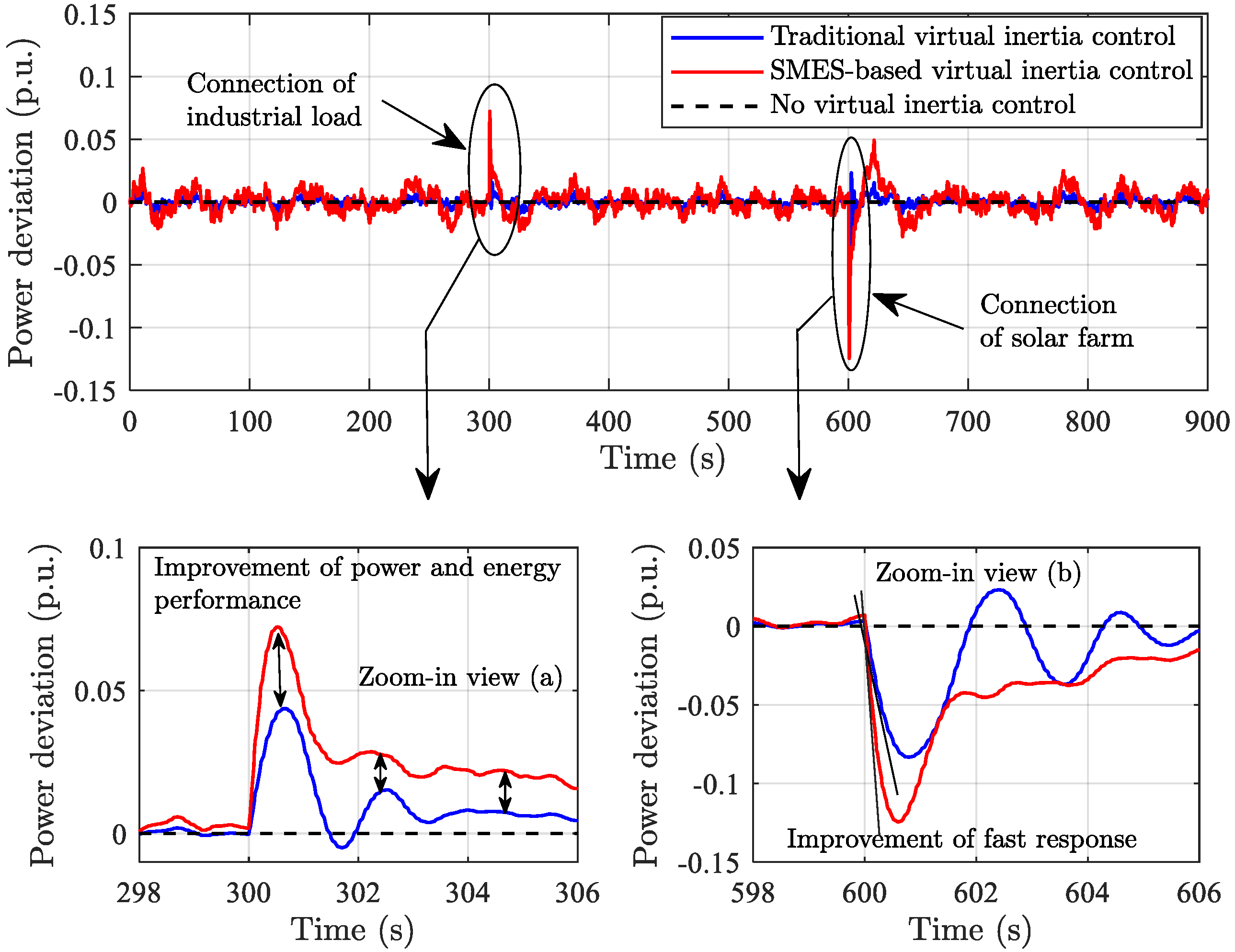
Figure 12 confirms that applying SMES-based virtual inertia control can significantly improve the inertia emulation capability in terms of high power/energy and fast response. Therefore, this scenario implies that the proposed SMES-based virtual inertia control is very robust against a wide range of microgrid operations, maintaining satisfying frequency stability even in extreme situations.
In summary, applying virtual inertia control topology into SMES system not only improves the inertia emulation capability but also reduces frequency oscillation and transient excursion, and shortens the stabilizing time, effectively enhancing the overall stability and robustness of the existing microgrid.

4.3. Stability Assessment under Low Inertia Microgrid Considering Time Delay Uncertianty

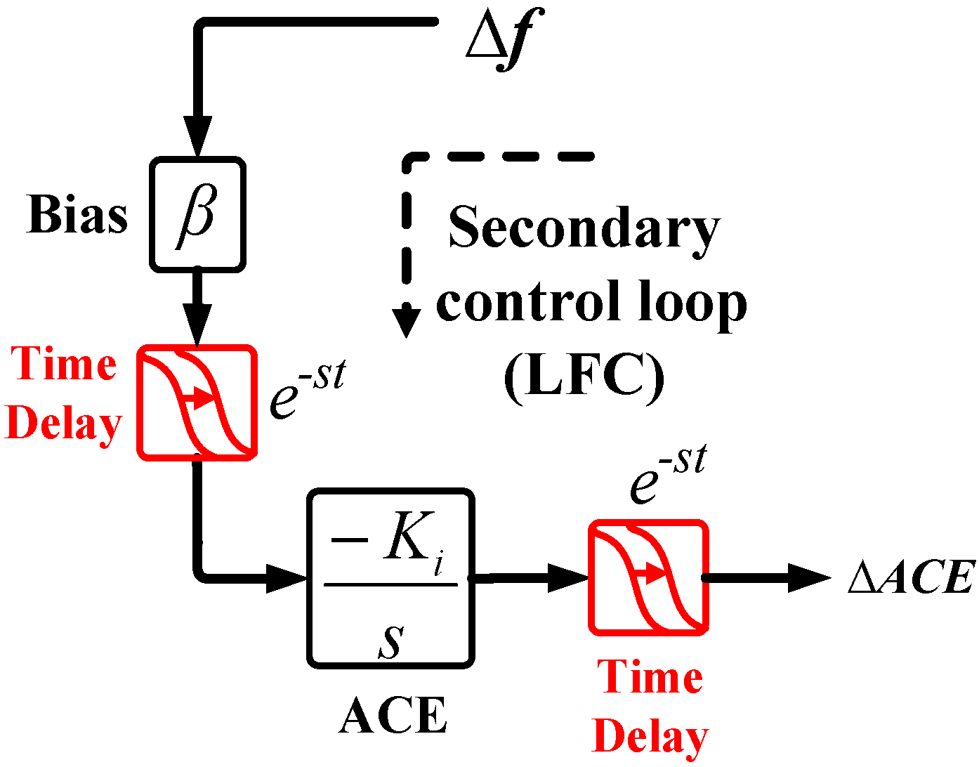
In real practice, rapid response and changing components of frequency are almost unobservable according to several filters and delays involved in the secondary control or load frequency control (LFC) process. Any signal filtering and processing introduces delays that should be considered [23]. This issue also complies with the European Network of Transmission System Operators for Electricity (ENTSO-E) recommendations. Thus, communication delays in LFC analysis are becoming more important challenges due to the expanding, restricting of functionality, physical setups, and complexity of the existing microgrids. Such a delay effect could significantly lead to the degradation of microgrid stability and performance, especially under the situations of low inertia.
The time delays in secondary control mainly exist in the communication channels between the microgrid control center and operating stations, specifically on the measured frequency from the remote terminal units (RTUs) to the microgrid control center, and on the generated signal from the microgrid control center to individual generation units. The delay system is expressed by an exponential function e−st, where t is the communication delay time. These delay systems are constructed as indicated in Figure 13 and modified to the dynamic model of the microgrid in Figure 2.
To investigate the robustness of the proposed SMES-based virtual inertia control approach, the severe operating conditions similar to Scenario 4.2 (i.e., high RESs and low loads) are implemented in this scenario while considering the communication delay effect. Typical filters and ACE signal use about 2 s or more for the data decision and acquisition cycles of the LFC [23]. Thus, in this study, a communication delay time (t) of 3 s is applied to evaluate the robustness of the proposed control approach.
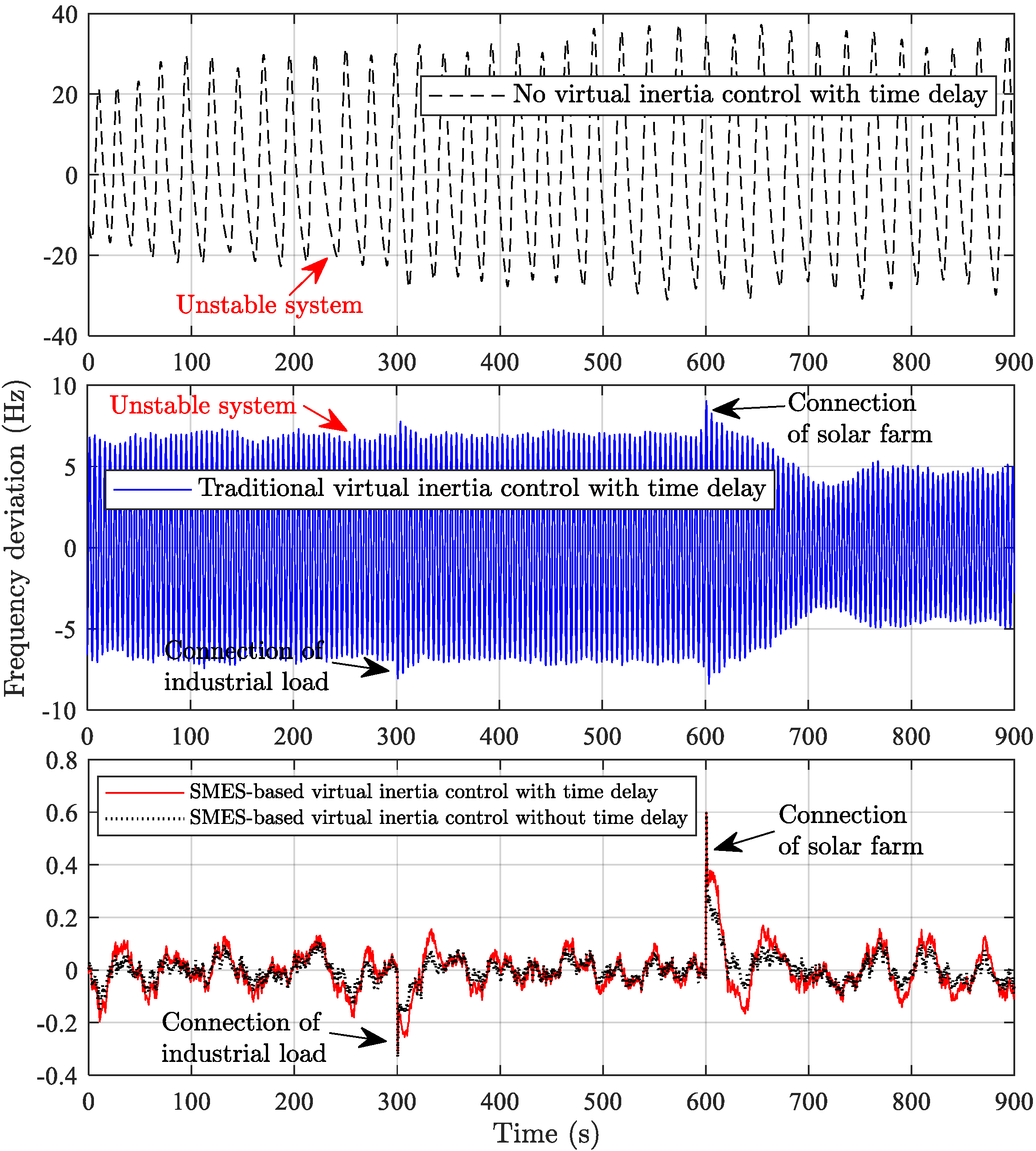
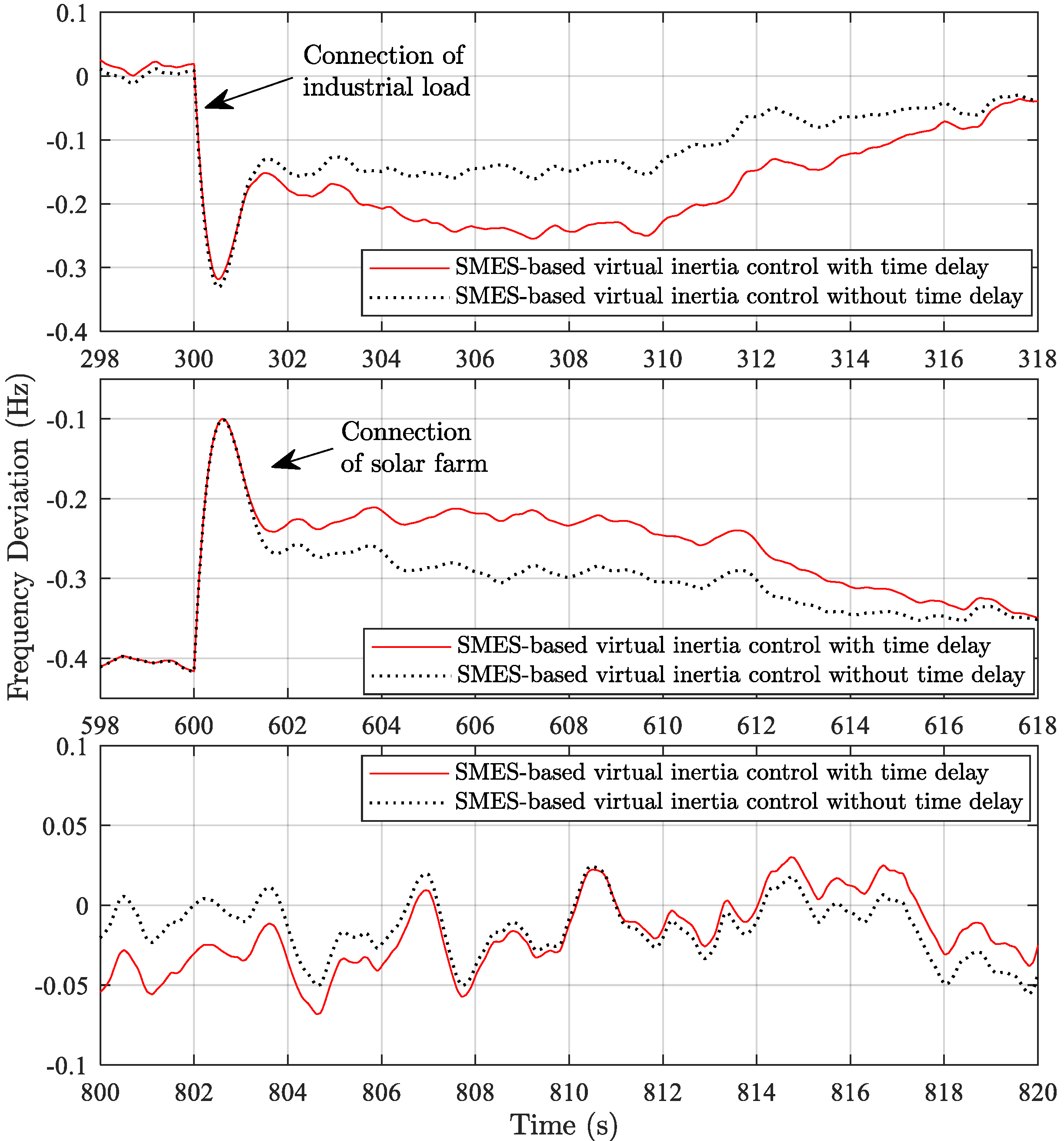
Figure 14 and Figure 15 show the microgrid response under the severe situation of low system inertia with the time delay effect. Clearly, the introduction of time delays significantly reduces the efficacy and robustness of the microgrid frequency in all cases. Larger frequency transients and deviations could be evidently observed. In the case of no virtual inertia control, the system frequency completely leads to an unstable condition, resulting in system collapse and wide-area power blackouts. Traditional ESS-based virtual inertia control also fails to stabilize the system frequency, leading to system collapse and power blackouts. It is confirmed that the microgrid frequency stability and performance are reduced when time delay is applied. On the contrary, the proposed SMES-based virtual inertia control could provide remarkable performance and maintain frequency stability within the permittable limit of ±0.1 Hz, due to its high power with fast response. This implies the security and robustness of the proposed control approach. 
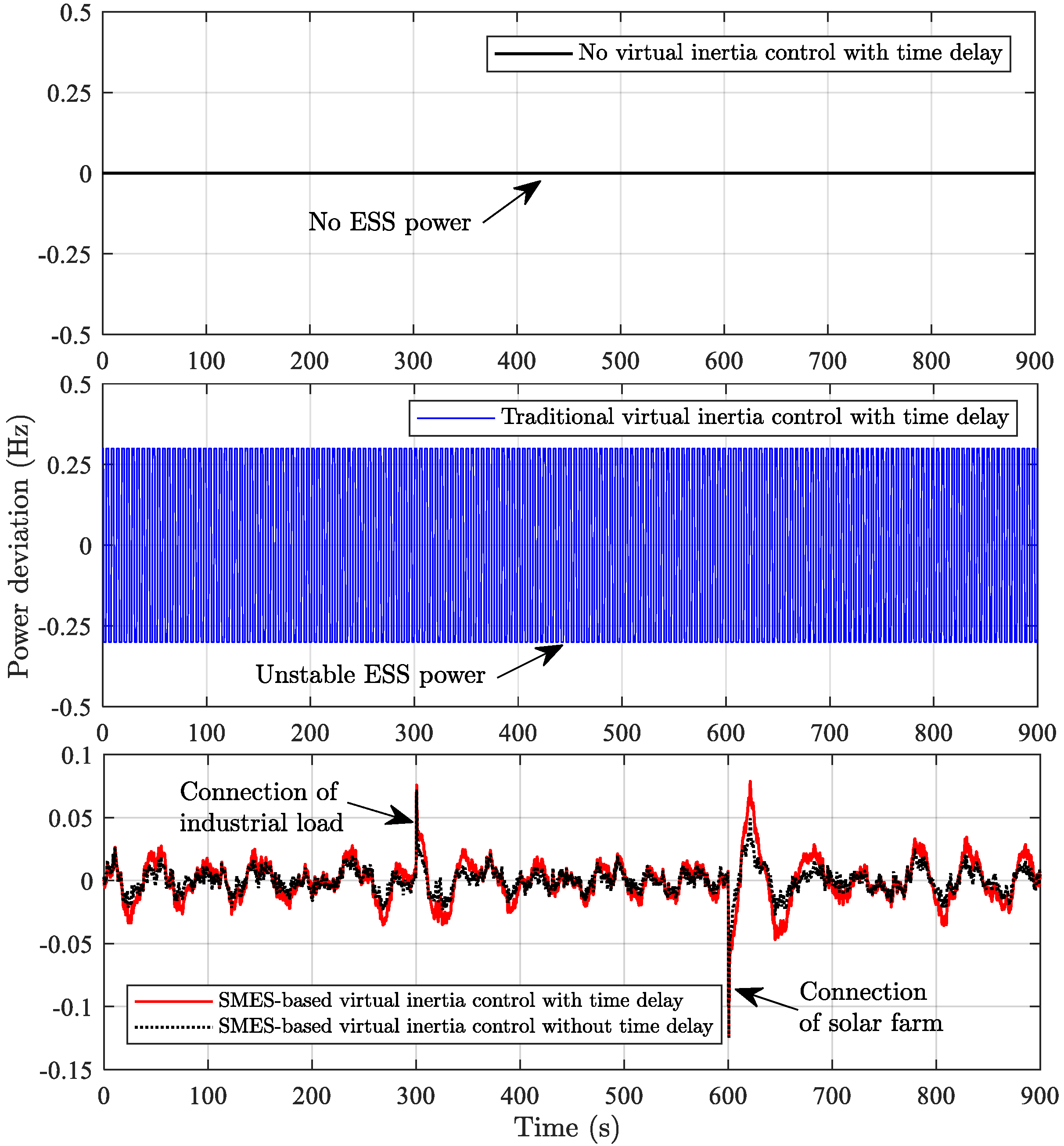
Figure 16 reveals the virtual inertia power response under the severe situation of low system inertia with time delay. Under the time delay effect, it is obvious that the inertia power in the case of traditional ESS-based virtual inertia control is in the critical unstable condition, reaching the ESS power capacity limit of ±0.3 p.u. This implies severe system instability, leading to system collapse. In the case of the proposed SMES-based virtual inertia control, more inertia power is required during the implementation of time delay to maintain the stable/robust frequency stability and performance within the permittable limit. Thus, it is confirmed that the effect of time delay can be suppressed by the proposed SMES-based virtual inertia control.

5. Conclusions

Considering inertia emulation capabilities, insufficient emulation of inertia power due to the lower and short-term power of storage systems could significantly lead to microgrid instability, cascading outages, and partial or complete power blackouts. To improve such capability, this paper applies a virtual inertia control topology to SMES technology. The study results indicate that SMES-based virtual inertia control provides better frequency performance and stability in terms of transient/peak deviation and settling time than traditional ESS-based virtual inertia control. This work shows the positive role of SMES in the improvement of inertia emulation and control against the high integration of RESs. It is obvious that applying virtual inertia control topology to SMES system not only improves the inertia emulation capability but also reduces frequency oscillation and transient excursion, and shortens the stabilizing time, effectively enhancing the overall stability and robustness of the existing microgrid. Hence, the proposed model and control technique will be important and useful for further analysis and studies of frequency stability/control with respect to virtual inertia emulation-based SMES capabilities. Additionally, the proposed collaboration technique can be expected as the smart stabilizing system in regard to inertia emulation for existing and future microgrids. This technique could be applied to any type of power systems with different characteristics, size, and complexity.

Author Contributions

This research was a collaborative effort between the authors. T.K. proposed the dynamic design of virtual inertia control-based SMES and wrote the paper. M.W. provided theoretical knowledge for inertia analysis. Y.M. provided theoretical knowledge in the energy and control domain and reviewed the paper. V.P. provided practical knowledge in SMES technology and proofread the paper.

Funding

This research was funded by Kyushu Institute of Technology and the APC was funded by MDPI.

Acknowledgments

This research was supported by the Power System and Renewable Energy Laboratory (Mitani-Watanabe Lab), Kyushu Institute of Technology, Fukuoka, Japan.

Conflicts of Interest

The authors declare no conflict of interest.

References

  1. Fathi, A.; Shafiee, Q.; Bevrani, H. Robust frequency control of microgrids using an extended virtual synchronous generator. IEEE Trans. Power Syst. 2018, 33, 6289–6297. [Google Scholar] [CrossRef]
  2. Rakhshani, E.; Rodriguez, P. Inertia Emulation in AC/DC Interconnected Power Systems using Derivative Technique considering Frequency Measurement Effects. IEEE Trans. Power Syst. 2017, 32, 3338–3351. [Google Scholar] [CrossRef]
  3. Rakhshani, E.; Remon, D.; Cantarellas, A.M.; Garcia, J.M.; Rodriguez, P. Virtual Synchronous Power Strategy for Multiple HVDC Interconnections of Multi-Area AGC Power Systems. IEEE Trans. Power Syst. 2017, 32, 1665–1677. [Google Scholar] [CrossRef]
  4. Rodriguez, P.; Rakhshani, E.; Mir Cantarellas, A.; Remon, D. Analysis of derivative control based virtual inertia in multi-area high-voltage direct current interconnected power systems. IET Gener. Transm. Distrib. 2016, 10, 1458–1469. [Google Scholar]
  5. Kerdphol, T.; Rahman, F.S.; Watanabe, M.; Mitani, Y. Robust Virtual Inertia Control of a Low Inertia Microgrid Considering Frequency Measurement Effects. IEEE Access 2019, 7, 57550–57560. [Google Scholar] [CrossRef]
  6. Kerdphol, T.; Rahman, F.S.; Mitani, Y. Virtual Inertia Control Application to Enhance Frequency Stability of Interconnected Power Systems with High Renewable Energy Penetration. Energies 2018, 11, 981. [Google Scholar] [CrossRef]
  7. Bevrani, H.; Ise, T.; Miura, Y. Virtual Synchronous Generators: A Survey and New Perspectives. Int. J. Electr. Power Energy Syst. 2014, 54, 244–254. [Google Scholar] [CrossRef]
  8. Tamrakar, U.; Shrestha, D.; Maharjan, M.; Bhattarai, B.; Hansen, T.; Tonkoski, R. Virtual Inertia: Current Trends and Future Directions. Appl. Sci. 2017, 7, 654. [Google Scholar] [CrossRef]
  9. D’Arco, S.; Suul, J.A.; Fosso, O.B. A Virtual Synchronous Machine implementation for distributed control of power converters in SmartGrids. Electr. Power Syst. Res. 2015, 122, 180–197. [Google Scholar] [CrossRef]
  10. D’Arco, S.; Suul, J.A. A synchronization controller for grid reconnection of islanded virtual synchronous machines. In Proceedings of the 2015 IEEE 6th International Symposium on Power Electronics for Distributed Generation Systems (PEDG), Aachen, Germany, 22–25 June 2015. [Google Scholar]
  11. Ali, M.H.; Wu, B.; Dougal, R.A. An overview of SMES applications in power and energy systems. IEEE Trans. Sustain. Energy 2010, 1, 38–47. [Google Scholar] [CrossRef]
  12. Muttaqi, K.M.; Islam, M.R.; Sutanto, D. Future Power Distribution Grids: Integration of Renewable Energy, Energy Storage, Electric Vehicles, Superconductor, and Magnetic Bus. IEEE Trans. Appl. Supercond. 2019, 29, 1–5. [Google Scholar] [CrossRef] [Green Version]
  13. Shayeghi, H.; Jalili, A.; Shayanfar, H.A. A robust mixed H2/H∞ based LFC of a deregulated power system including SMES. Energy Convers. Manag. 2008, 49, 2656–2668. [Google Scholar] [CrossRef]
  14. Pappachen, A.; Peer Fathima, A. Load frequency control in deregulated power system integrated with SMES-TCPS combination using ANFIS controller. Int. J. Electr. Power Energy Syst. 2016, 82, 519–534. [Google Scholar] [CrossRef]
  15. Ngamroo, I.; Karaipoom, T. Improving low-voltage ride-through performance and alleviating power fluctuation of DFIG wind turbine in DC microgrid by optimal SMES with fault current limiting function. IEEE Trans. Appl. Supercond. 2014, 24, 1–5. [Google Scholar] [CrossRef]
  16. Ngamroo, I.; Karaipoom, T. Cooperative Control of SFCL and SMES for Enhancing Fault Ride Through Capability and Smoothing Power Fluctuation of DFIG Wind Farm. IEEE Trans. Appl. Supercond. 2014, 24, 1–4. [Google Scholar] [CrossRef]
  17. Ali, M.H.; Park, M.; Yu, I.K.; Murata, T.; Tamura, J.; Wu, B. Enhancement of transient stability by fuzzy logic-controlled SMES considering communication delay. Int. J. Electr. Power Energy Syst. 2009, 31, 402–408. [Google Scholar] [CrossRef]
  18. Ali, M.H.; Murata, T.; Tamura, J. Transient stability enhancement by fuzzy logic-controlled SMES considering coordination with optimal reclosing of circuit breakers. IEEE Trans. Power Syst. 2008, 23, 631–640. [Google Scholar] [CrossRef]
  19. Zhang, H.; Kang, Y.; Zhu, P.C.; Kong, X.J.; Liu, P.; Chen, J. Enhancement of generator transient stability using superconducting magnetic energy storage (SMES) in dynamic simulation test of power system. In Proceedings of the 4th IEEE International Conference on Power Electronics and Drive Systems, Denpasar, Indonesia, 25 October 2001. [Google Scholar]
  20. Abu-Siada, A.; Islam, S. Application of SMES unit in improving the performance of an AC/DC power system. IEEE Trans. Sustain. Energy 2011, 2, 109–121. [Google Scholar] [CrossRef]
  21. Magdy, G.; Shabib, G.; Elbaset, A.A.; Mitani, Y. A Novel Coordination Scheme of Virtual Inertia Control and Digital Protection for Microgrid Dynamic Security Considering High Renewable Energy Penetration. IET Renew. Power Gener. 2019, 13, 462–474. [Google Scholar] [CrossRef]
  22. Kundur, P. Power System Stability and Control; McGraw-Hill: New York, NY, USA, 1994; ISBN 007035958X. [Google Scholar]
  23. Bevrani, H. Robust Power System Frequency Control, 2nd ed.; Springer: New York, NY, USA, 2014; ISBN 978-0-387-84877-8. [Google Scholar]
  24. Magdy, G.; Mohamed, E.A.; Shabib, G.; Elbaset, A.A.; Mitani, Y. SMES based a new PID controller for frequency stability of a real hybrid power system considering high wind power penetration. IET Renew. Power Gener. 2018, 11, 1304–1313. [Google Scholar] [CrossRef]
  25. Mohamed, E.A.; Magdy, G.; Shabib, G.; Elbaset, A.A.; Mitani, Y. Digital coordination strategy of protection and frequency stability for an islanded microgrid. IET Gener. Transm. Distrib. 2018, 12, 3637–3646. [Google Scholar] [CrossRef]
  26. Nair, P.S.C. Effect of Superconducting Magnetic Energy Storage on Automatic Generation Control. IEEE Trans Power Syst. 1992, 7, 1266–1273. [Google Scholar]
  27. AEMC Reliability Panel. Stage One Final Determination: Review of the Frequency Operating Standard; Australian Energy Market Operator: Sydney, Australia, 2017.
Figure 1. A diagram of the microgrid with superconducting magnetic energy storage (SMES)-based inertia control loop.
Energies 12 03902 g001
Figure 2. Dynamic model of the microgrid with SMES-based inertia control loop for frequency stability synthesis.
Energies 12 03902 g002
Figure 3. Basic configuration of the studied SMES.
Energies 12 03902 g003
Figure 4. Dynamic model of SMES for frequency stability study [13,14,26].
Energies 12 03902 g004
Figure 5. Dynamic models of (a) the inertia control-based derivative method [2,3,4,5,6,21] and (b) the normal energy storage system (ESS)-based inverter [2,3,4,5,6,21].
Energies 12 03902 g005
Figure 6. Dynamic model of SMES-based virtual inertia control for frequency stability enhancement.
Energies 12 03902 g006
Figure 7. Power disturbances in the presence of low wind speed/solar irradiation and heavy load consumption.
Energies 12 03902 g007
Figure 8. Microgrid response under high system inertia.
Energies 12 03902 g008
Figure 9. Inertia power response under high system inertia.
Energies 12 03902 g009
Figure 10. Power disturbances in the presence of high wind speed/solar irradiation and light load consumption.
Energies 12 03902 g010
Figure 11. Microgrid response under low system inertia.
Energies 12 03902 g011
Figure 12. Inertia power response under low system inertia.
Energies 12 03902 g012
Figure 13. Dynamic model of the time delay in a secondary control or load frequency control (LFC) system.
Energies 12 03902 g013
Figure 14. Microgrid response under low system inertia considering the time delay effect.
Energies 12 03902 g014
Figure 15. Zoom-in views of microgrid response under low system inertia considering the time delay effect.
Energies 12 03902 g015
Figure 16. Inertia power response under low system inertia considering the time delay effect.
Energies 12 03902 g016
Table 1. Control parameters of the studied microgrid.
ParameterValue
Bias factor, β (p.u.MW/Hz)1
Secondary control constant, Ki (s)0.05
Governor time constant, Tg (s)0.1
Turbine time constant, Tt (s)0.4
Primary control constant, R (Hz/p.u.MW)2.4
Load damping constant, D (p.u.MW/Hz)0.015
System inertia constant, H (p.u.MW s)0.083
Virtual inertia control constant, J (s)0.8
Wind turbine time constant, TWT (s)1.5
Solar system time constant, TPV (s)1.85
Kid control gain, (kV/kA)0.2
SMES control gain, KSMES (kV/MW)0.6
Converter time constant, TDC (s)10
Inductor rated current, Id0 (kA)4.5
SMES coil, L (H)2.65

