Article

Smart Battery Pack for Electric Vehicles Based on Active Balancing with Wireless Communication Feedback

1
Department of Electric, Electronic and Information Engineering, University of Bologna, 40136 Bologna, Italy
2
School of Automation, Northwestern Polytechnical University, Xi’an 710072, China
3
Applied Electronics Department, Technical University of Cluj-Napoca, 400114 Cluj-Napoca, Romania
4
Energy Technology Department, Aalborg University, 9220 Aalborg, Denmark
*
Author to whom correspondence should be addressed.
Energies 2019, 12(20), 3862; https://doi.org/10.3390/en12203862
Submission received: 16 September 2019 / Revised: 8 October 2019 / Accepted: 11 October 2019 / Published: 12 October 2019

Abstract

:
In this paper, the concept of smart battery pack is introduced. The smart battery pack is based on wireless feedback from individual battery cells and is capable to be applied to electric vehicle applications. The proposed solution increases the usable capacity and prolongs the life cycle of the batteries by directly integrating the battery management system in the battery pack. The battery cells are connected through half-bridge chopper circuits, which allow either the insertion or the bypass of a single cell depending on the current states of charge. This consequently leads to the balancing of the whole pack during both the typical charging and discharging time of an electric vehicle and enables the fault-tolerant operation of the pack. A wireless feedback for implementing the balancing method is proposed. This solution reduces the need for cabling and simplifies the assembling of the battery pack, making also possible a direct off-board diagnosis. The paper validates the proposed smart battery pack and the wireless feedback through simulations and experimental results by adopting a battery cell emulator.

1. Introduction

The need of reduction of greenhouse gas emissions, along with the continuous depletion of the fossil fuel reserves, drives the demand of new means of transportation that are environmentally sustainable and do not depend on traditional fuel. One of the most potential solutions is the adoption of electrical vehicles (EVs) thanks to their zero emission and the use of batteries as energy supply. Among the different battery technologies, lithium-ion (Li-ion) batteries are preferred thanks to their higher energy density, longer life cycle and no memory effect [1,2,3]. Moreover, the prices of this kind of batteries are continuously decreasing, making them a good choice for EV applications. The necessity of increasing the driving range, extending the battery lifetime, and ensuring their right behavior has attracted a lot of attention from both the industry and the academia. For these reasons, new concepts of battery packs and battery management systems (BMSs) have been developed in literature.
BMSs are very important for the suitable operation of any battery pack. They are in charge of ensuring the battery operation into the safe operating area, monitoring the state of the battery pack, and recording useful data [4,5]. Among the different tasks of the BMS [6,7], one of the most important tasks is to estimate and balance the state of charge (SOC) of the battery cells. The estimation is very important since battery cells can be damaged in case of both overcharge and overdischarge events. On the other hand, the balancing allows using the whole stored energy by avoiding stopping the pack when only one of the cells reaches the minimum SOC. These differences during discharging are due to the different capacities of the cells [8,9]. Indeed, the manufacturing process cannot guarantee the same capacity for all the produced cells. Moreover, the aging process differently affects the cells by resulting in a wide range of the capacity values. For these reasons, balancing methods are adopted. Two main balancing techniques can be distinguished: passive methods and active techniques [10,11]. The first ones dissipate the exceeded energy of unbalanced cells on external resistors in order to balance the cells during charging time. This method is simple to implement; however, the cell’s temperature increases due to high losses, the efficiency is limited, and no balance is achieved during discharging. For these reasons, active balancing techniques have been proposed [12,13]. They are able to balance the SOC by moving the energy among the cells thanks to additional circuits. The benefit is to increase the useful capacity of the battery pack as shown in Figure 1.
A module-integrated distributed battery energy storage that includes a DC/DC converter in each module has been proposed in Reference [14]. In Reference [15], the active balancing method is instead based on a flyback DC/DC converter topology able to move energy from one single cell to the stack or vice versa. Several examples of solutions that adopt additional energy storage elements can be found in literature [16,17,18]. The authors in Reference [19] proposed an interleaved equalization architecture for series-connected battery strings. However, all these solutions require either additional energy storage elements or DC/DC converters at a cell/module level along with their inherent fast switching. In order to avoid the use of those elements, of particular interest is the cell-module bypass methods. A BMS architecture based on the cell bypass concept has been proposed in Reference [20]. It is able to dynamically insert/bypass a cell in a battery module in order to ensure the balancing among the cells. However, no intelligence is added in the cell by keeping all the computational effort in a main controller and the applications are limited to low-to-medium power, such as electric bicycles. In Reference [21], a dynamically reconfigurable independent cellular switching circuit has been proposed for managing battery modules. It is able to reconfigure the battery module on-line by achieving serial, parallel, and hybrid connection configurations. The authors in Reference [22] proposed a multilayer modular balancing strategy for individual cells. They demonstrate a good balancing of the SOCs, but the cell structure is more complex requiring inductors at a cell level. Dynamically reconfigurable battery systems were also proposed in literature where both the cell level and the module level can be reconfigured in real time according to the load profile [23]. These solutions employ a built-in switching-array circuitry that however increases the complexity of the system.
All the previous works are based on wire communication to get different measurements from all battery cells. In the recent years, wireless communication has also gained interest in the field to avoid the wiring harness that reduces the reliability and the scalability of the battery pack. The authors in Reference [24] proposed a new smart cell by integrating some BMS functionalities at the cell level and by adopting radio-frequency identification (RFID) for cell-to-cell communication within the pack. However, it adopts additional energy storage elements for achieving the SOC balancing. In Reference [25], a smart wireless battery-monitoring system has been proposed for EVs. In this case, the wireless communication is only adopted to monitor the batteries and a passive balancing method is implemented. A distributed battery system with wireless control has introduced in Reference [26]. To the best knowledge of the authors, this is the only work that handles both the monitoring and the control, providing a reference voltage to the cells, through wireless communication. However, the power transfer is also wireless, requiring power electronic circuitry for the DC–AC conversion.
In this paper, a new smart battery pack (SBP) based on wireless feedback is proposed. The cell bypass concept is adopted to achieve active SOC balancing, and smartness at the cell level is introduced. The battery cell is indeed connected to a half-bridge chopper circuit in order to insert or bypass the cell. A microprocessor is embedded per each cell and it can control the insertion of the cell, perform a distributed monitoring of both the SOC and the state of health (SOH) and record useful data at a cell level. A main controller can collect the states of each cell and perform the balancing algorithm. The BMS, which is usually implemented in additional boxes, is then integrated into a power electronic system. Wireless communication ensures the data exchange between the individual slaves (the microprocessors of the cells) and the master (the main controller) and provides the control signals for the cells. This solution allows for complexity reduction, simplified manufacturing, easier maintenance, and more environmentally friendly recycling due to the absence of huge amounts of cables needed for communication. Furthermore, the proposed solution is easy to scale up and it can boost second-life battery applications, such as renewable energy storage systems (RESS). It is widely known that in EV applications batteries that reach 80% of the nominal capacity are considered to be at the end of life. However, these batteries can be adopted in applications where the size of the battery pack is not so important. Moreover, thanks to the recorded data at a cell level, an easier management of the battery pack composed by second-life batteries is achieved.
The original contribution of this paper mainly consists in transforming the conventional battery cell into an intelligent unit able to:
  • Communicate wirelessly with the battery pack controller providing advanced cell balancing, monitoring, and fault tolerant operation;
  • Estimate its own SOC and the possibility to evaluate SOH;
  • Be easily integrated in a very large battery pack by enhancing the scalability.
The paper is structured in the following way. Section 2 presents the proposed SBP by discussing the adopted balancing algorithm and the implemented wireless protocol stack. After that, simulation results are provided in order to show the good behavior of the SOC balancing technique. Experimental results are given in Section 4. Finally, conclusions are drawn in Section 5.

2. Smart Battery Pack

In this section, the basic concept of the proposed SBP is provided. After that, the balancing algorithm is given along with the adopted SOC estimation technique. Finally, the wireless protocol stack implementation for both the master and slaves is shown.

2.1. Basic Concept

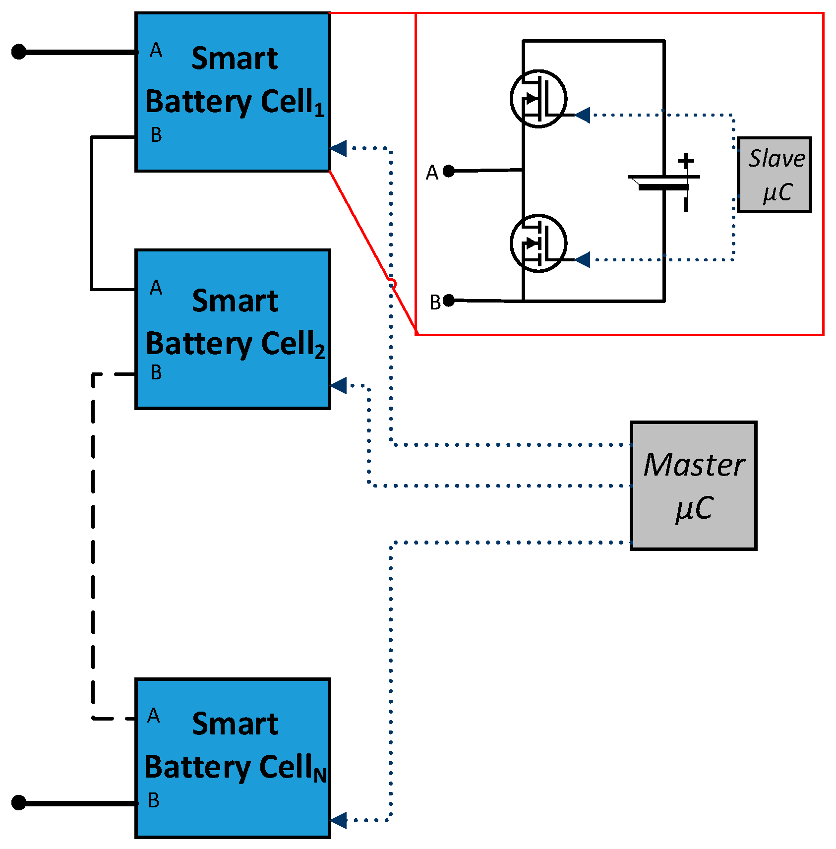
The proposed SBP consists of a series connection of N smart battery cells (SBCs) that communicate with a master controller. Each SBC is composed of a battery cell connected to an electronic board consisting of a half-bridge chopper circuit and a microcontroller. The latter controls the switches and is also able to estimate the SOC of the cell (see Section 2.2) and to communicate with the master controller (see Section 2.3). The cell voltage, the output current, and the cell temperature are measured and sent to the controller. The block diagram of the SBP is shown in Figure 2.

2.2. Balancing Algorithm

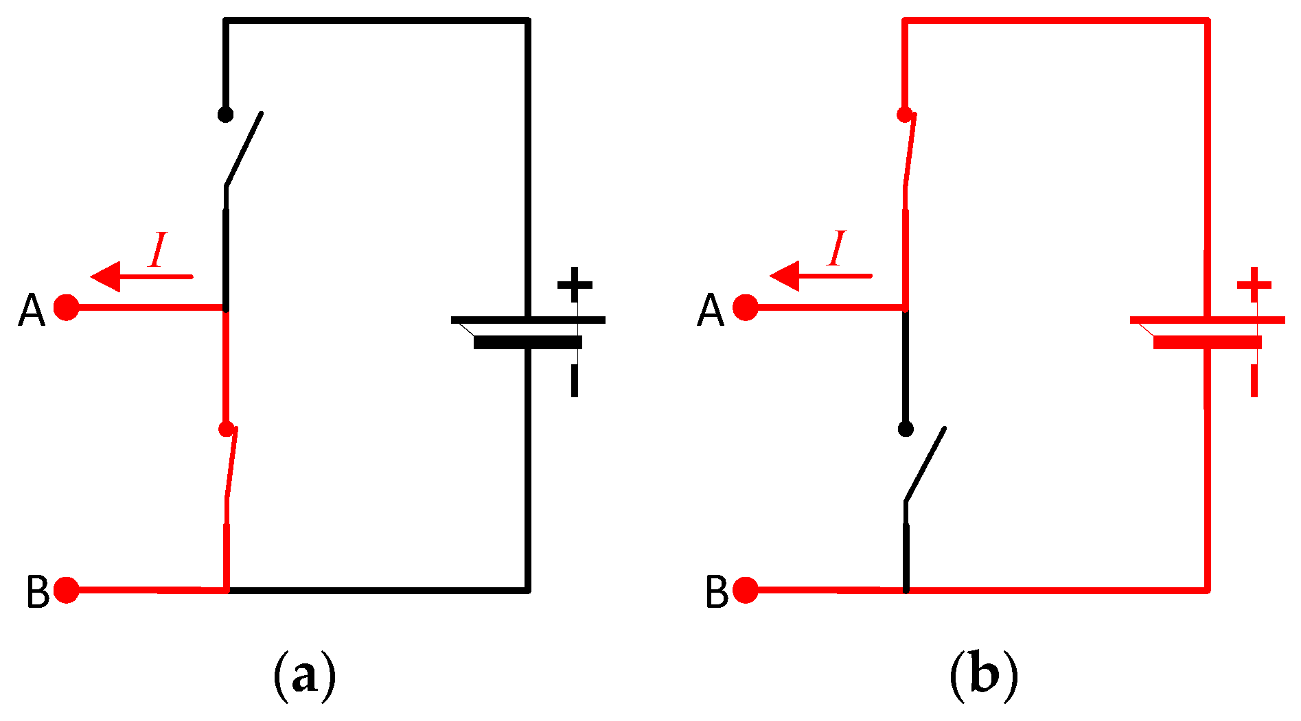
In order to improve the consistency of the batteries, an efficient strategy is proposed for balancing the SBP [27]. Instead of transferring energy from one battery to another, the SBP only inserts and bypasses the cells using the half-bridge chopper circuits as shown in Figure 3.
In order to insert or bypass the cell, the only operation of the topology is switching the status of the two MOSFETs. When the status of the lower MOSFET is on and that of the upper MOSFET is off, the cell is bypassed as shown in Figure 3a. On the contrary, if the status of the upper MOSFET is on and that of the lower MOSFET is off, the cell is inserted into the battery pack as shown in Figure 3b.
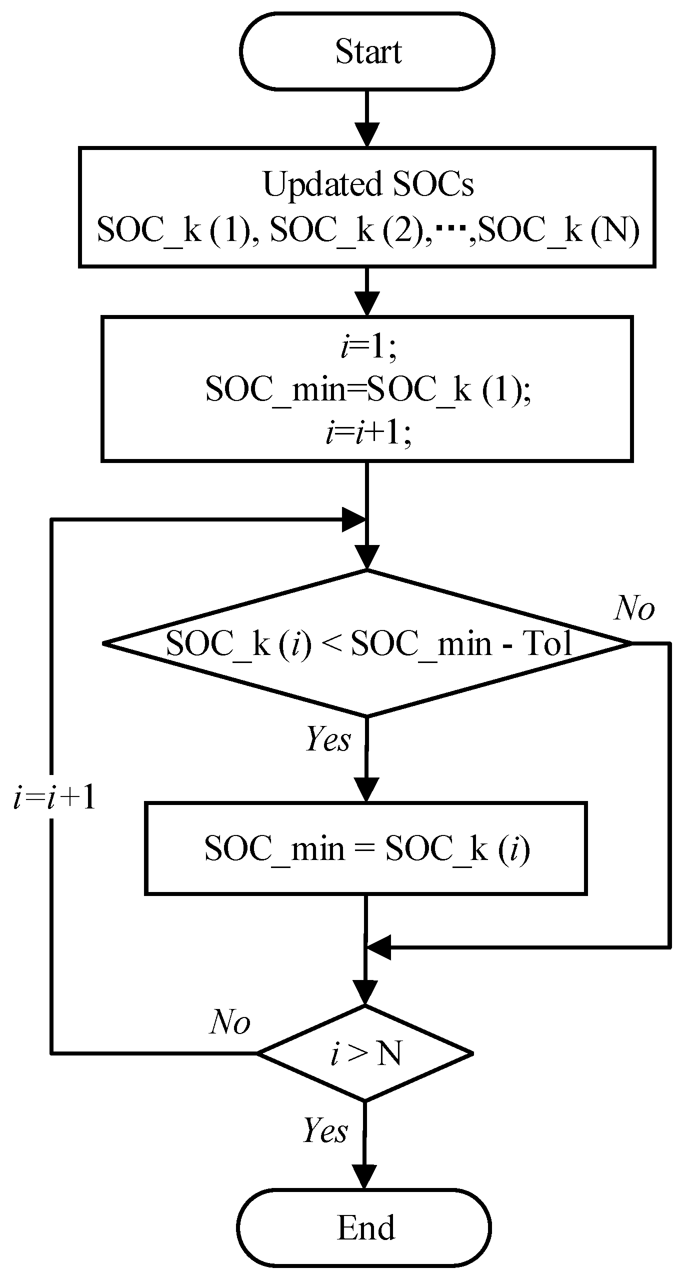
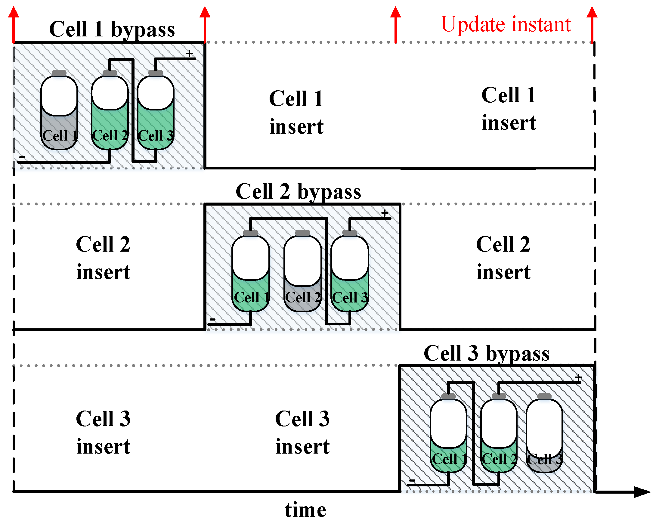
During charging and discharging processes, the SOC of each cell is evaluated by a local microcontroller. Then, all the estimated SOCs are sent to the main control that decides which cells to be inserted in the circuit. During discharging, the cell with the lowest SOC is bypassed; on the other hand, during the charging process, the cell with the highest SOC is removed from the circuit. The bypass decision is made each time when the master controller sends information to the salves. The flowchart of the balancing algorithm is shown in Figure 4, where SOC_k is the state of charge of the cell at the current time k; SOC_min is the minimum SOC among the cells in the battery pack at the time k; N represents the total number of the cells and i identifies the cells; Tol is a tolerance introduced for avoiding switches among cells when the SOCs are very close to each other. After having received the estimated SOCs from each slave, the master finds the cell with the lowest SOC in the battery pack. Then, the command is sent from the master to the slave to bypass or insert the specific cell. The balancing process during discharging is shown in Figure 5.

2.2.1. SOC Estimation

The state of charge provides an indication of how much energy is left in the battery. Therefore, it is an important index for the balance strategy. In literature, different techniques have been proposed with the aim to improve and accelerate the estimation of the SOC. However, the SOC estimation is out of the topic of this paper and then an easy and accepted method is implemented in the SBP, i.e., the coulomb counting method. It is used in each slave microcontroller of SBCs to estimate the SOC of each battery cell. The equation for evaluating the battery SOC through the coulomb counting method is as follows:
S O C ( k + 1 ) = S O C ( k ) η T s C b I ( k ) ,
where η is the coulomb efficiency, Cb is the battery capacity, Ts is the sampling time, and I(k) is the measured battery current at the instant k.

2.2.2. Capacity Gain Evaluation

In order to demonstrate the benefits in terms of useful capacity of the active balancing methods in comparison with those associated with the passive techniques, a statistical analysis is carried out in this section. The useful capacity Cu of a battery pack can be defined as:
C u = 0 t 10 % i ( t )   d t ,
where i(t) is the battery current and t10% is the time when the SOC is equal to 10%. Moreover, the SOC can be written as:
S O C = 1 1 C b 0 t i ( t )   d t .
Then, when the SOC is 10%, Equation (3) can be rewritten as:
0.1 = 1 1 C b 0 t 10 % i ( t )   d t     0 t 10 % i ( t )   d t = 0.9 C b .
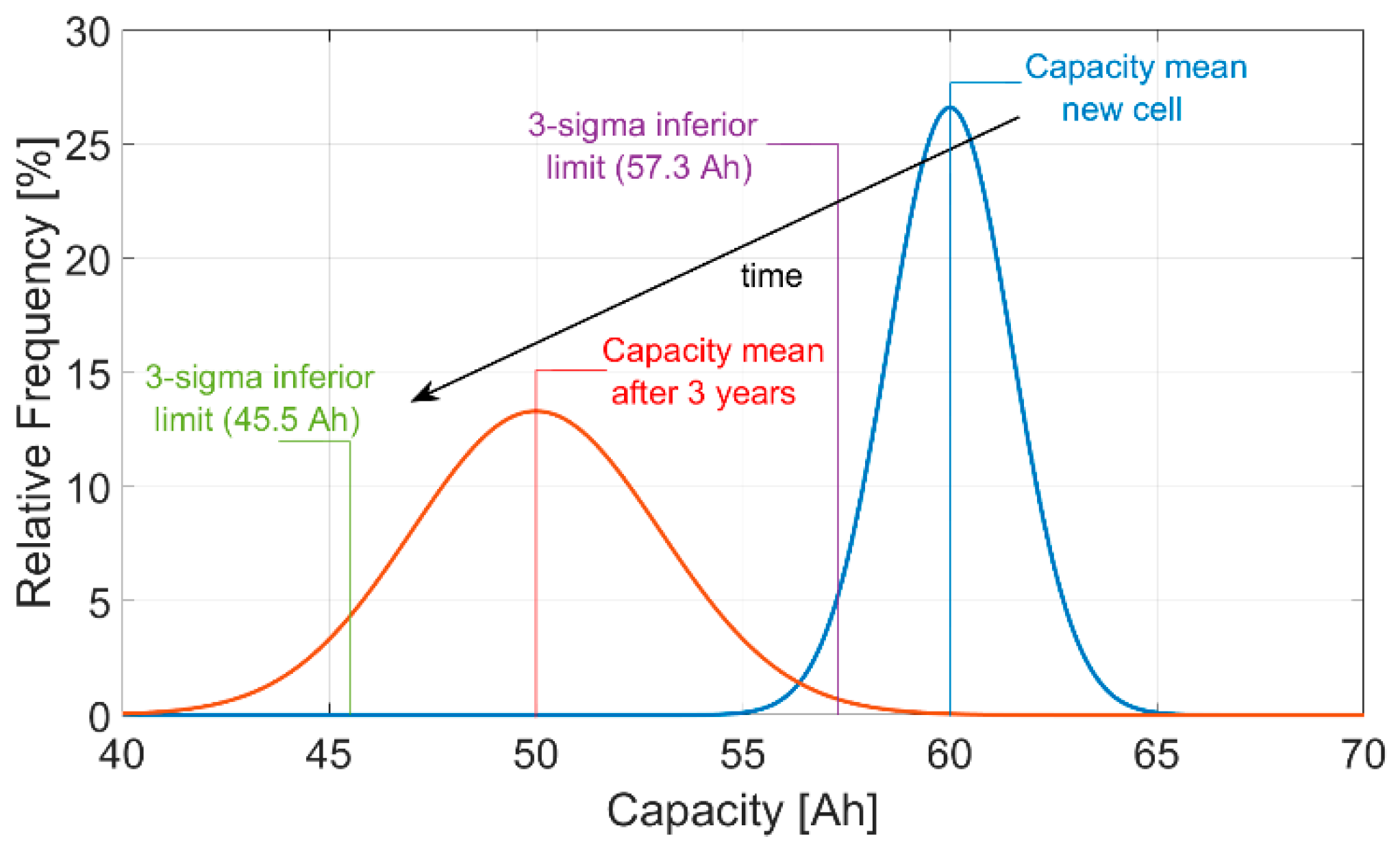
Then, the useful capacity can be evaluated as the 90% of the battery capacity. However, the latter is not fixed, and it depends on different factors (manufacturing, aging, etc.). As described in Reference [28], the capacity value distribution can be seen as a normal distribution with a mean value µ and a standard deviation σ. Considering new battery cells of 60 Ah, the capacity mean value is 60 Ah and the standard deviation is considered equal to 1.5%. After 3 years, the capacity mean value is reduced to 50 Ah and the standard deviation is about 3%, as shown in Reference [28]. Figure 6 shows the trend of the normal distribution of the capacity values. It can be seen that µ decreases with the aging and at the same time σ increases.
A classical battery pack without active balancing is limited by the lowest battery capacity, that is, the 99.7% of the cases is within the 3-sigma range. On the other hand, a battery pack with active balancing is able to use the capacity mean of the pack. Therefore, considering a new cell and a 3-year-old cell, the obtained useful capacities are shown in Table 1.

2.3. Wireless Protocol Stack

This subsection describes the wireless protocol stack for both the master and the slaves. Wireless communication relies on the Wi-Fi standard, but this subsection will focus mostly on the application layer. The lower levels of the protocol stack, being specific to the hardware used to obtain experimental data, are described in Section 4. However, it is important to mention that the master is running a Linux distribution with the Hostapd user space daemon managing the access point (AP) and the created network. The slaves instead rely on the Texas Instruments real-time operating system (TI-RTOS) to implement the Wi-Fi stack.

2.3.1. Master

At the application layer, a User Datagram Protocol (UDP) socket is created. All messages sent by the master have the same structure: a timestamp field indicating the exact time at which the packet is issued, a command code identifying the action that the slaves need to take, a command array that encodes the half-bridge state associated to each cell (cell inserted or bypassed), and an IP array of all connected devices. The command array and the IP array number of elements are equal to the number of slaves connected. The slaves should identify their own IP in the IP array. The index of the IP array that matches the slave’s own IP is the index used by the master to identify the slave. This index should be used by the slave to extract its corresponding command in the command array. This way of addressing each slave allows for a dynamic address allocation that enables an easy scalability of the system.
Four command codes are defined: SOC_REQEST, CMD, EXE, and SAFESTATE corresponding to four types of packets. The SOC_REQUEST command is used to request the SOC from each battery cell. For CMD packets, the command array field contains the actual command. Elements in the command array are Boolean, with 0 indicating an insert request and 1 indicating a bypass request. The slaves should send back the element of the command array corresponding to their indices, confirming that the CMD packet is properly received and decoded. EXE packets are used to confirm the execution of the previously sent command encoded in the CMD packet. CMD and EXE packets form a handshake protocol. The SAFESTATE command code is sent as a result of a communication error.
The master application layer is implemented as a state machine. After initializing the WLAN, the master issues an SOC_REQUEST command. After all slaves reply with the requested SOC, the master identifies the cell that needs to be bypassed and constructs the command array accordingly. The CMD and EXE handshake sequence is further executed. For each command sent, the slaves should send a packet as a response.
Based on the slaves’ response, the command execution status is determined. A simplified diagram of the master application layer is presented in Figure 7 while a detailed description of the command execution status is presented in Table 2.

2.3.2. Slave

Two main functionalities need to be implemented at the slaves’ application level: computing the SOC of the battery cell and establishing communication with the master. A detailed description of the SOC estimation implementation was given in Section 2.2. For implementing the Wi-Fi communication stack, the TI-RTOS is used which allows working with sockets in a similar manner as for the master’s Linux application.
The slave application waits for packets sent by the master, extracts the slave index by parsing the IP array, and decodes the command code. Once the command code is decoded, it replies with the estimated SOC in case a SOC_REQUEST packet is received or sends back the corresponding element in the command array if a CMD or EXE packet was received. In case of an EXE command, the slave application is also responsible for generating the gate drive signals for the half-bridge chopper circuit in order to insert or bypass the cell, depending on the content of the command array field. When an SAFESTATE packet is received, the slave is required to insert the battery cell.
A timeout limit is also defined at the slave’s application level. If no packets are received from the host for a predefined time interval (3 s), the slaves will enter in the SAFESTATE mode.

3. Simulation Results

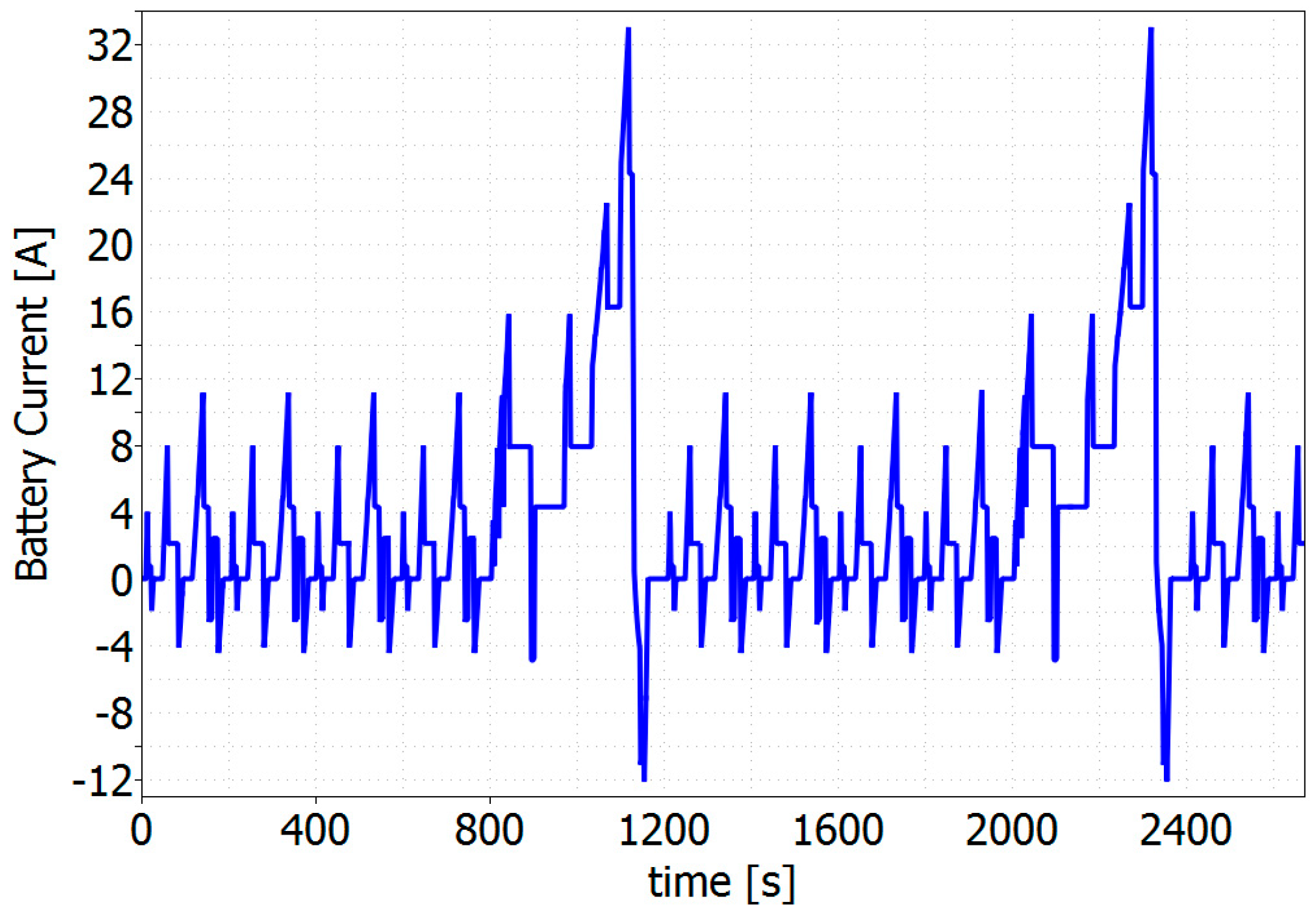
In this section, simulation results are provided in order to demonstrate the superior performance of the proposed SBP in comparison with that of a conventional pack. The latter is usually composed of a series connection of battery cells. The classical BMS adopts a passive balancing technique where the SOC balancing is only ensured during the charging process. Then, a realistic assumption is that the battery cells are balanced at the beginning of the discharging process, i.e., maximum SOC deviation of 1% among the cells. The test is made considering an EV application, and then a real driving profile is considered during the simulations, i.e., the Multi-New European Driving Cycle (NEDC) profile shown in Figure 8. To speed up the simulations, twelve Li-ion cells rated as 3.2 V/60 Ah are considered in the battery pack. Similar results are expected if the proposed SBP is compared with a battery pack with active balancing. However, the proposed solution integrates the BMS functionality in the pack by achieving the monitoring and the balancing through wireless communication.
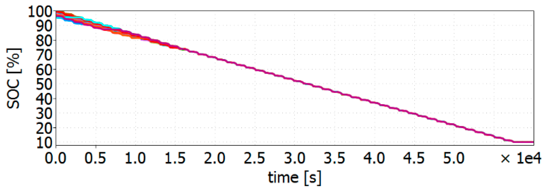
The first simulation aims to show the balancing performance of the proposed SBP. Then, a variation of 5% is imposed on the initial SOCs. Figure 9 shows that the battery pack with the proposed balancing technique balances the SOCs within 4 h with a sampling time equal to 1 s. The SBP is now compared with a classical battery pack. For this comparison, 2 cells with different aging are considered. The first set consists of cells at the beginning of life (BoL) and their nominal capacity is equal to 60 Ah with a standard deviation of 1.5%. The second set considers 3-year-old cells with a nominal capacity and a standard deviation equal to 50 Ah and 3%, respectively, as shown in Section 2.2.2.
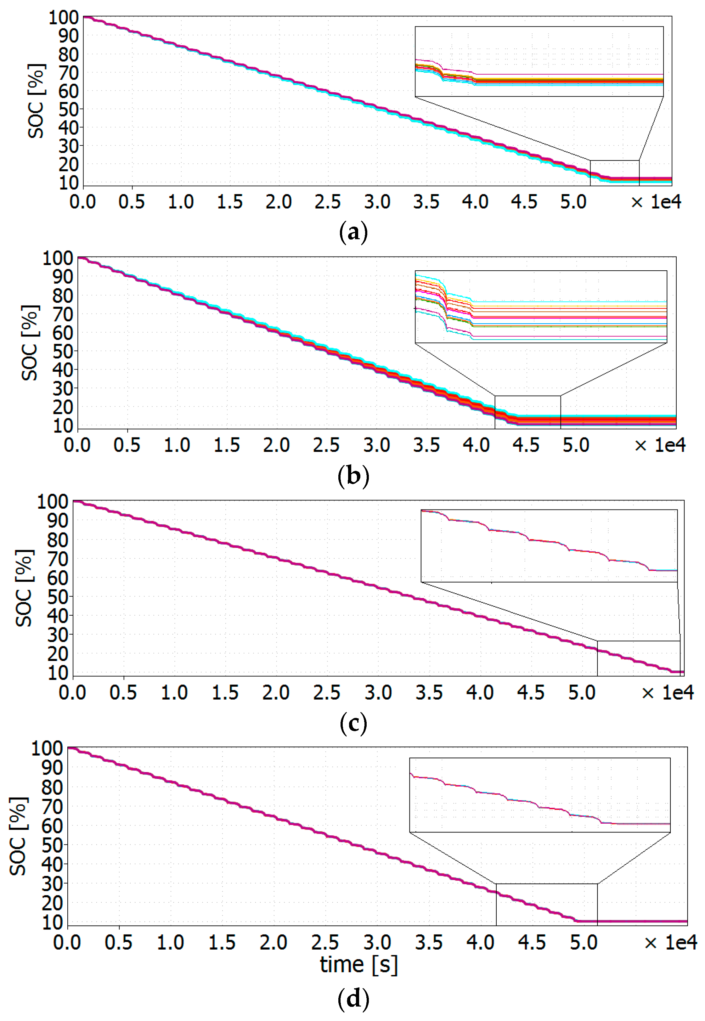
Figure 10a,b show the results in case of passive balancing with cells at the BoL and after 3 years, respectively. It is worth noting that the battery pack stops delivering power at the output as soon as one of the cells reaches 10% of the SOC, as visible in the magnification given in Figure 10a,b. This is due to the safety reason for avoiding overdischarges. Figure 10c,d show the results in case of the proposed SBP again with cells at BoL and after 3 years, respectively. Additionally, in this case, the battery pack stops delivering power at the output when the SOC reaches 10%, but this event happens much later, as it can be seen in the insets of Figure 10c,d. Table 3 summarizes the time when the battery pack stops delivering power.

4. Experimental Results

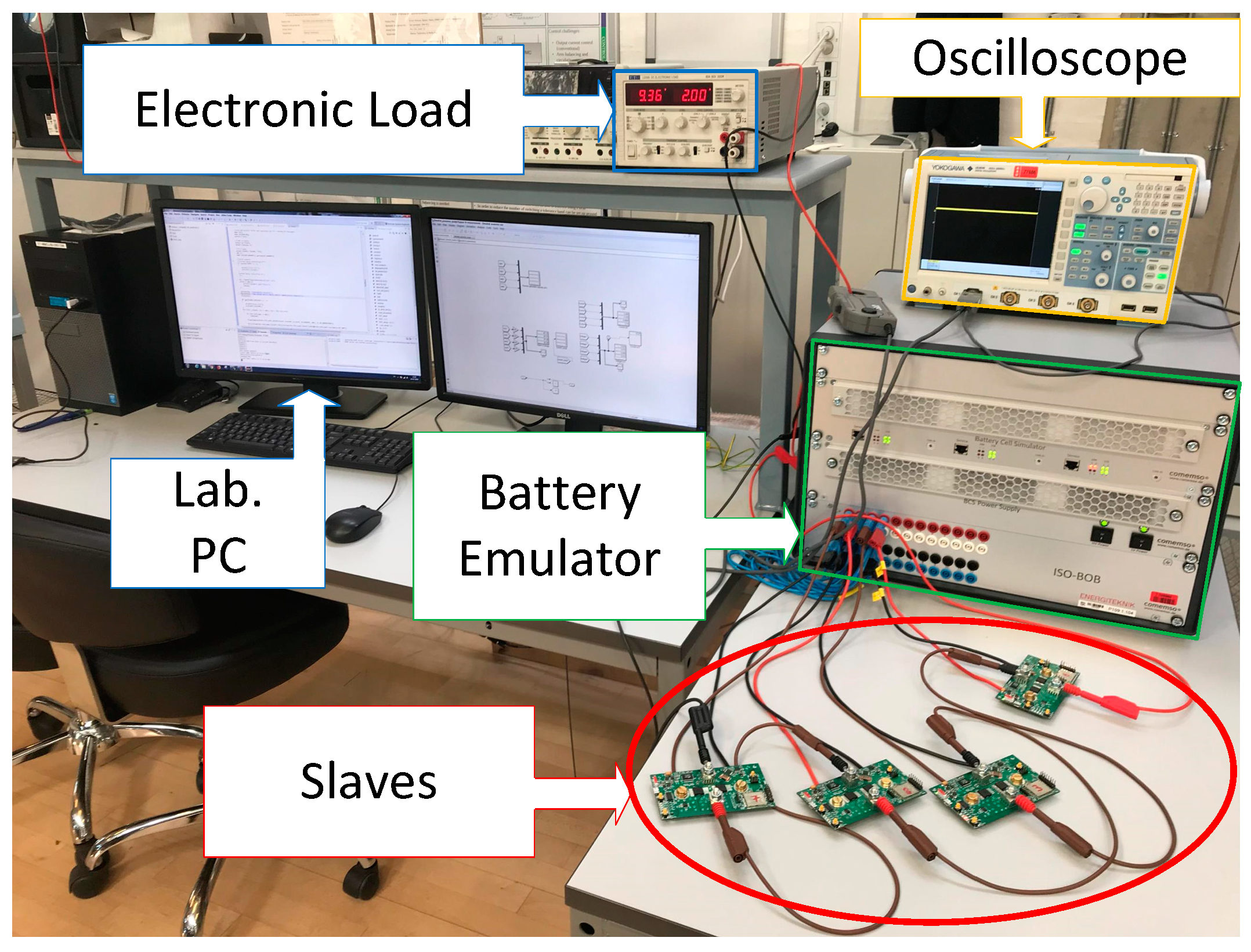
The proposed SBP is intended for EV applications as discussed in the previous section, but not limited to it. However, in order to validate the proposed SBP, a down-scaled experimental prototype has been built. It consists of a COMEMSO battery cell emulator adopted for emulating 4 battery cells. It is controlled by a laboratory computer through CAN communication. A battery model is implemented in Simulink and the CANoe software tool from Vector Informatik Gmbh works as an interface between the Matlab model and the battery emulator. The real current is sensed and sent to the model. It evaluates the SOC and the Open Circuit Voltage (OCV) thanks to a pre-loaded OCV-SOC table. Then, the battery voltage is obtained and sent to the battery emulator that emulates it at the output. In the conventional battery pack, the 4 cells are simply connected in series. On the other hand, in the proposed SBP, the outputs of the battery emulator corresponding to the 4 cells are connected to the slave boards, as shown in Figure 11.
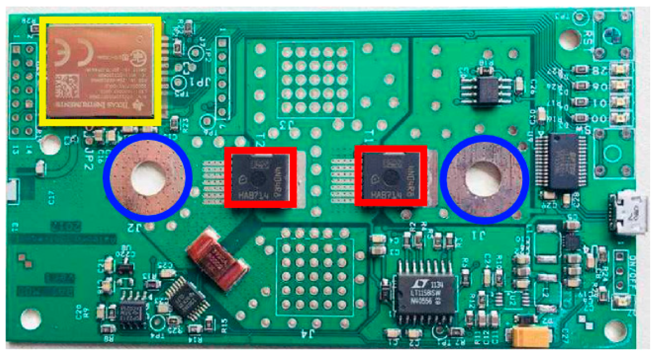
Figure 12 shows the slave board PCB with terminal connection for the battery cell (blue), switches (red), and a CC3200MOD Wi-Fi module from Texas Instruments (yellow). The master is used for implementing the discussed BMS. The master algorithm is implemented on a Snickerdoodle board featuring a Xilinx ZYNQ system on chip and a Texas Instruments WiLink8 RF transceiver module that enables Wi-Fi communication. The WiLink8 transceiver implements the physical layer of the Wi-Fi communication stack and it is interfaced to the ZYNQ through an SDIO interface. A pre-built Linux image running on the ZYNQ manages the upper layers of the Wi-Fi protocol. The Hostapd user space daemon is responsible for implementing the AP functionality and managing the Wi-Fi network created. An electronic load is connected to the output of the battery pack. The battery pack is discharged with a constant current equal to 2 A. The adopted current probe is a 701930 Yokogawa hall effect current probe and the voltage–current ratio is equal to 10 mV/1A.
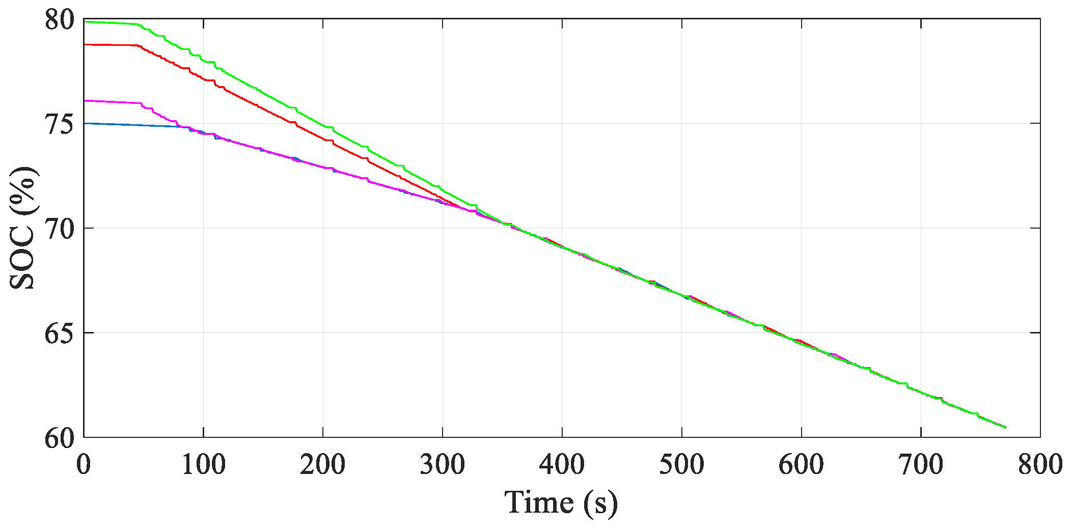
Firstly, the SOC balancing performance of the proposed SBP has been validated. In order to speed up the experimental validation, the nominal battery capacity of 60 Ah has been reduced 60 times, so a nominal capacity of 1 Ah is considered.
A variation of 5% on the initial SOC values is also given to the emulated cells. Figure 13 shows the SOCs of the cells and demonstrates that the proposed balancing algorithm is able to balance the cells in 300 s.
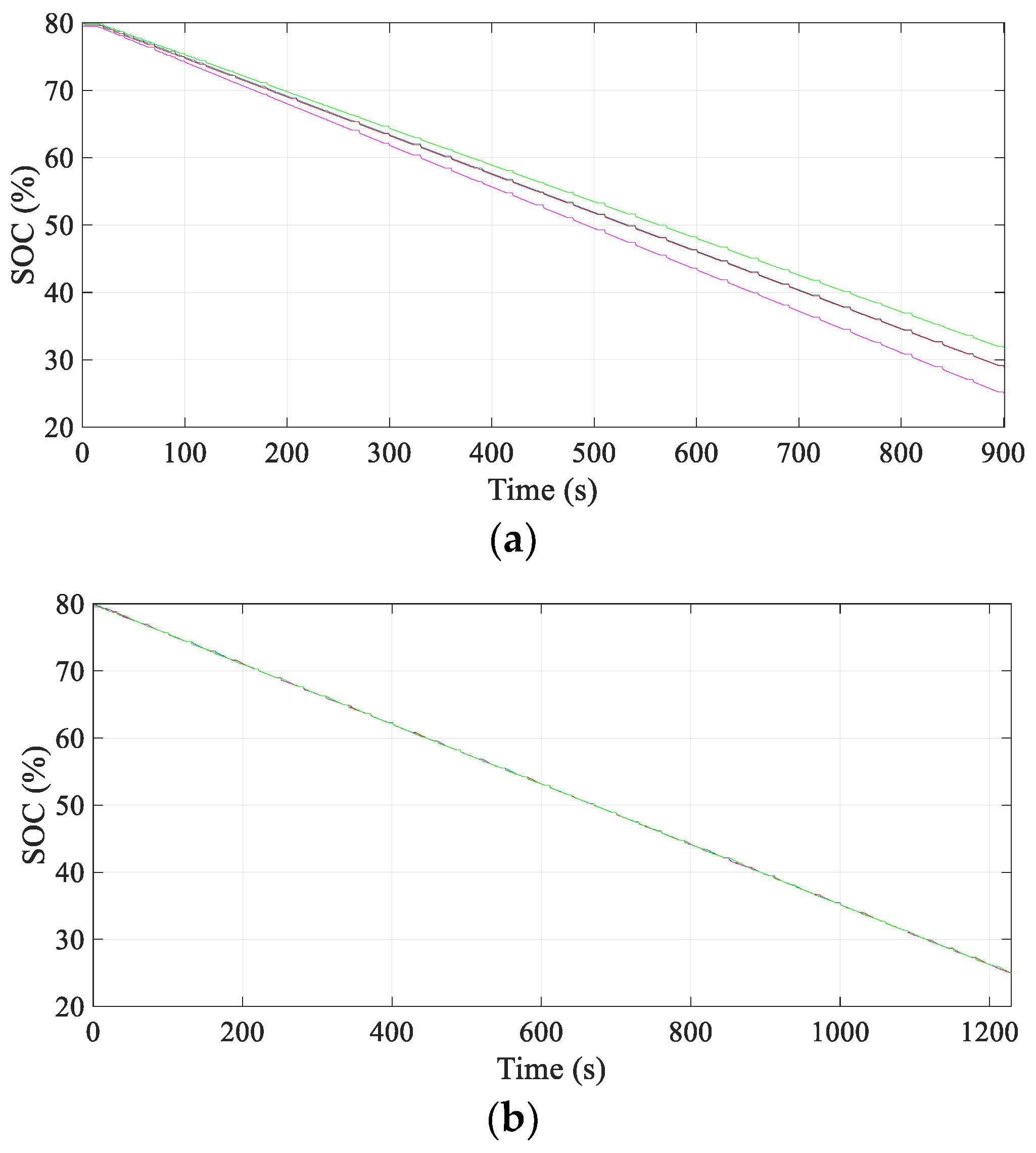
Another experiment was carried out in order to compare the proposed SBP with a classical battery pack in terms of the driving range. Figure 14 shows the SOC of the cells (4 in the considered battery pack) when the initial SOC is equal for all of them and a variation of 5% is considered for the battery capacity.
In case of passive balancing, the SOCs are already quite different and the 25% of SOC is reached in 15 min, as shown in Figure 14a. On the other hand, Figure 14b shows the results achieved with the proposed active balancing. It is worth noting that the 4 SOC curves are overlapping each other in Figure 14b. In this case, the 25% of SOC is reached in 20 min. Then, an increment in the battery pack operational time is demonstrated and it is justified by an increment of the useful capacity of the SBP. As already mentioned, the SBP is based on wireless feedback in order to send the estimated SOC from the slaves to the master and control the insertion/bypass of the cells. In this situation, losses of packages in the communication can happen and it could prevent the proper behavior of the battery pack. For this reason, the SAFESTATE mode has been introduced, as explained in Section 2.3. A loss in communication is emulated in order to demonstrate the right operation of the SBP in safe mode.
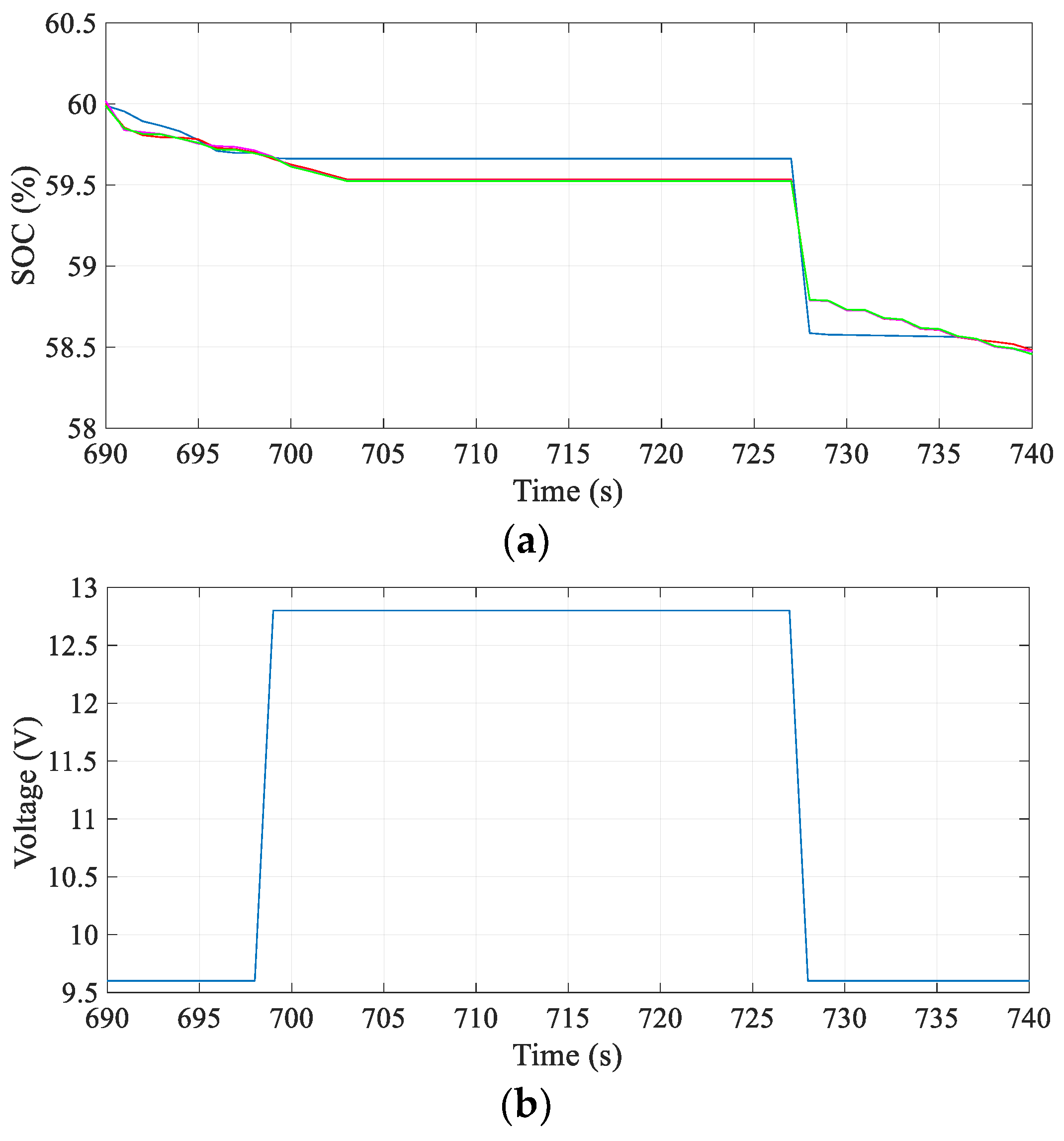
Figure 15a shows the SOCs of the 4 battery cells with the proposed SBP and at around 700 s the communication is lost. At this point, the SOCs remain constant in Figure 15a because the master does not get the SOC updates from the slaves so the SOCs of the cells are unknown to the main controller. As soon as the communication is re-established, the master receives the estimated SOCs from the slaves and then a step is visible in Figure 15a (this is only due to the fact that the master does not know the SOC when the communication is lost, so the real SOC does not obviously present any jumps). At the same time, the output battery pack voltage is measured and shown on the same time scale of the SOC in Figure 15b.
It is worth noting that in correspondence of the communication loss the battery pack voltage is higher and equal to 12.8 V. This is due to the fact that in safe mode all the cells are inserted in the circuit. In this case, the possibility to balance the cells is lost but the power delivery is still ensured. As soon as the communication is reestablished, the master starts again to balance the cells and it bypasses the cell with the lowest SOC from the circuit. Therefore, the battery pack voltage returns to its original value at 728 s.
The wireless feedback has also been tested in city environment in Reference [29] by showing an increase of package losses. However, the good behavior of the SBP is still ensured.

5. Conclusions

In this paper an SBP based on wireless feedback that can be suitable for EV applications has been proposed. It consists of a series connection of SBCs which in turn are composed of a battery cell connected to a half-bridge chopper circuit. The proposed solution allows inserting or bypassing a single cell in the circuit by leading a higher usable capacity and a fault-tolerant operation. The main novelty is the introduction of the wireless feedback, which reduces the need of cabling and simplifies the assembly of the battery pack. Cells at the BoL and 3-year-old cells have been considered in simulation in order to demonstrate the better performances of the proposed solution in comparison with those of the battery packs that adopt passive balancing techniques. Experimental results have been illustrated by using a battery emulator and the developed SBC PCB board. The results show the good balancing achieved with the proposed SBP and the right operation of the wireless feedback. Some losses of communication have been also considered during the experiments and it has been demonstrated the good safe operation mode in these cases. Finally, it can be concluded that the integration of the BMS functionalities in the battery pack along with the wireless feedback is possible. This leads to a much easier mounting and cell replacement in EV applications. Moreover, thanks to its high scalability, the proposed SBP can be easily adapted for second-life battery applications, such as in residential battery energy storage systems. Future works consist of additional analysis of the wireless communication, and in particular, further investigations should be done to choose the best protocol for high-density network applications.

Author Contributions

Conceptualization, M.R., J.M., T.G., G.G., and R.T.; methodology, M.R., J.M., T.G., G.G., and R.T.; software, M.R., J.M., and T.G.; validation, M.R., J.M., and T.G.; formal analysis, M.R.; investigation, M.R., J.M., and T.G.; writing of original draft preparation, M.R.; writing of review and editing, M.R., J.M., T.G., G.G., and R.T.; visualization, M.R., J.M., T.G., G.G., and R.T.

Funding

This research received no external funding.

Conflicts of Interest

The authors declare no conflicts of interest.

References

  1. Andwari, A.M.; Pesiridis, A.; Rajoo, S.; Martinez-Botas, R.; Esfahanian, V. A review of Battery Electric Vehicle technology and readiness levels. Renew. Sustain. Energy Rev. 2017, 78, 414–430. [Google Scholar] [CrossRef]
  2. Cano, Z.P.; Banham, D.; Ye, S.; Hintennach, A.; Lu, J.; Fowler, M.; Chen, Z. Batteries and fuel cells for emerging electric vehicle markets. Nat. Energy 2018, 3, 279–289. [Google Scholar] [CrossRef]
  3. Saw, L.H.; Ye, Y.; Tay, A.A. Integration issues of lithium-ion battery into electric vehicles battery pack. J. Clean. Prod. 2016, 113, 1032–1045. [Google Scholar] [CrossRef]
  4. Lu, L.; Han, X.; Li, J.; Hua, J.; Ouyang, M. A review on the key issues for lithium-ion battery management in electric vehicles. J. Power Sourc. 2013, 226, 272–288. [Google Scholar] [CrossRef]
  5. Lelie, M.; Braun, T.; Knips, M.; Nordmann, H.; Ringbeck, F.; Zappen, H.; Sauer, D. Battery Management System Hardware Concepts: An Overview. Appl. Sci. 2018, 8, 534. [Google Scholar] [CrossRef]
  6. Shen, P.; Ouyang, M.; Lu, L.; Li, J.; Feng, X. The Co-estimation of State of Charge, State of Health and State of Function for Lithium-ion Batteries in Electric Vehicles. IEEE Trans. Veh. Technol. 2018, 67, 92–103. [Google Scholar] [CrossRef]
  7. Naha, A.; Khandelwal, A.; Hariharan, K.S.; Kaushik, A.; Yadu, A.; Kolake, S.M. On-Board Short-Circuit Detection of Li-ion Batteries Undergoing Fixed Charging Profile as in Smartphone Applications. IEEE Trans. Ind. Electron. 2019, 66, 8782–8791. [Google Scholar] [CrossRef]
  8. Zhou, L.; Zheng, Y.; Ouyang, M.; Lu, L. A study on parameter variation effects on battery packs for electric vehicles. J. Power Sourc. 2017, 364, 242–252. [Google Scholar] [CrossRef]
  9. Ye, M.; Song, X.; Xiong, R.; Sun, F. A Novel Dynamic Performance Analysis and Evaluation Model of Series-Parallel Connected Battery Pack for Electric Vehicles. IEEE Access 2019, 7, 14256–14265. [Google Scholar] [CrossRef]
  10. Daowd, M.; Omar, N.; Van Den Bossche, P.; Van Mierlo, J. Passive and active battery balancing comparison based on MATLAB simulation. In Proceedings of the 2011 IEEE Vehicle Power and Propulsion Conference, Chicago, IL, USA, 6–9 September 2011; pp. 1–7. [Google Scholar]
  11. Lee, S.W.; Choi, Y.G.; Kang, B. Active Charge Equalizer of Li-Ion Battery Cells Using Double Energy Carriers. Energies 2019, 12, 2290. [Google Scholar] [CrossRef]
  12. Baronti, F.; Roncella, R.; Saletti, R. Performance comparison of active balancing techniques for lithium-ion batteries. J. Power Sour. 2014, 267, 603–609. [Google Scholar] [CrossRef] [Green Version]
  13. Caspar, M.; Eiler, T.; Hohmann, S. Systematic Comparison of Active Balancing: A Model-Based Quantitative Analysis. IEEE Trans. Veh. Technol. 2018, 67, 920–934. [Google Scholar] [CrossRef]
  14. Li, Y.; Han, Y. A Module-Integrated Distributed Battery Energy Storage and Management System. IEEE Trans. Power Electron. 2016, 31, 8260–8270. [Google Scholar] [CrossRef]
  15. Einhorn, M.; Roessler, W.; Fleig, J. Improved Performance of Serially Connected Li-Ion Batteries With Active Cell Balancing in Electric Vehicles. IEEE Trans. Veh. Technol. 2011, 60, 2448–2457. [Google Scholar] [CrossRef]
  16. Narayanaswamy, S.; Kauer, M.; Steinhorst, S.; Lukasiewycz, M.; Chakraborty, S. Modular Active Charge Balancing for Scalable Battery Packs. IEEE Trans. Very Large Scale Integr. Syst. 2017, 25, 974–987. [Google Scholar] [CrossRef]
  17. Lukasiewycz, M.; Kauer, M.; Steinhorst, S. Synthesis of Active Cell Balancing Architectures for Battery Packs. IEEE Trans. Comput. Des. Integr. Circuits Syst. 2016, 35, 1876–1889. [Google Scholar] [CrossRef]
  18. Baronti, F.; Fantechi, G.; Roncella, R.; Saletti, R. High-efficiency digitally controlled charge equalizer for series-connected cells based on switching converter and super-capacitor. IEEE Trans. Ind. Inf. 2013, 9, 1139–1147. [Google Scholar] [CrossRef]
  19. Zhang, C.; Shang, Y.; Li, Z.; Cui, N. An interleaved equalization architecture with self-learning fuzzy logic control for series-connected battery strings. IEEE Trans. Veh. Technol. 2017, 66, 10923–10934. [Google Scholar] [CrossRef]
  20. Manenti, A.; Abba, A.; Merati, A.; Savaresi, S.M.; Geraci, A. A new BMS architecture based on cell redundancy. IEEE Trans. Ind. Electron. 2011, 58, 4314–4322. [Google Scholar] [CrossRef]
  21. Gunlu, G. Dynamically Reconfigurable Independent Cellular Switching Circuits for Managing Battery Modules. IEEE Trans. Energy Convers. 2017, 32, 194–201. [Google Scholar] [CrossRef]
  22. Cao, X.; Zhong, Q.C.; Qiao, Y.C.; Deng, Z.Q. Multilayer Modular Balancing Strategy for Individual Cells in a Battery Pack. IEEE Trans. Energy Convers. 2018, 33, 526–536. [Google Scholar] [CrossRef]
  23. Lin, N.; Ci, S.; Wu, D.; Guo, H. An Optimization Framework for Dynamically Reconfigurable Battery Systems. IEEE Trans. Energy Convers. 2018, 33, 1669–1676. [Google Scholar] [CrossRef]
  24. Otto, A.; Rzepka, S.; Mager, T.; Michel, B.; Lanciotti, C.; Günther, T.; Kanoun, O. Battery Management Network for Fully Electrical Vehicles Featuring Smart Systems at Cell and Pack Level; Meyer, G., Ed.; Advanced Microsystems for Automotive Applications 2012; Springer: Berlin/Heidelberg, Germany, 2012. [Google Scholar]
  25. Mathew, S.A.; Prakash, R.; John, P.C. A smart wireless battery monitoring system for electric vehicles. In Proceedings of the 2012 12th International Conference on Intelligent Systems Design and Applications (ISDA), Kochi, India, 27–29 November 2012; pp. 189–193. [Google Scholar]
  26. Qahouq, J.A.A.; Cao, Y. Distributed battery system with wireless control and power transfer—A concept introduction. Conf. Proc. IEEE Appl. Power Electron. Conf. Expo. 2018, 2018, 344–347. [Google Scholar]
  27. Majmunovic, B.; Sarda, R.; Teodorescu, R.; Lascu, C.; Ricco, M. Highly efficient smart battery pack for EV drivetrains. In Proceedings of the 2017 IEEE Vehicle Power and Propulsion Conference (VPPC), Belfort, France, 11–14 December 2017; pp. 1–5. [Google Scholar]
  28. Jiang, Y.; Jiang, J.; Zhang, C.; Zhang, W.; Gao, Y.; Guo, Q. Recognition of battery aging variations for LiFePO4 batteries in 2nd use applications combining incremental capacity analysis and statistical approaches. J. Power Sourc. 2017, 360, 180–188. [Google Scholar] [CrossRef]
  29. Lafrenz, J.L.; Scheff, P.; Ricco, M.; Kerekes, T.; Olsen, R.L.; Teodorescu, R.; Liserre, M. Application Layer Design for Smart Battery Pack Control with Wi-Fi ® Feedback. In Proceedings of the 2018 IEEE Energy Conversion Congress and Exposition (ECCE), Portland, OR, USA, 23–27 Septemeber 2018. [Google Scholar]
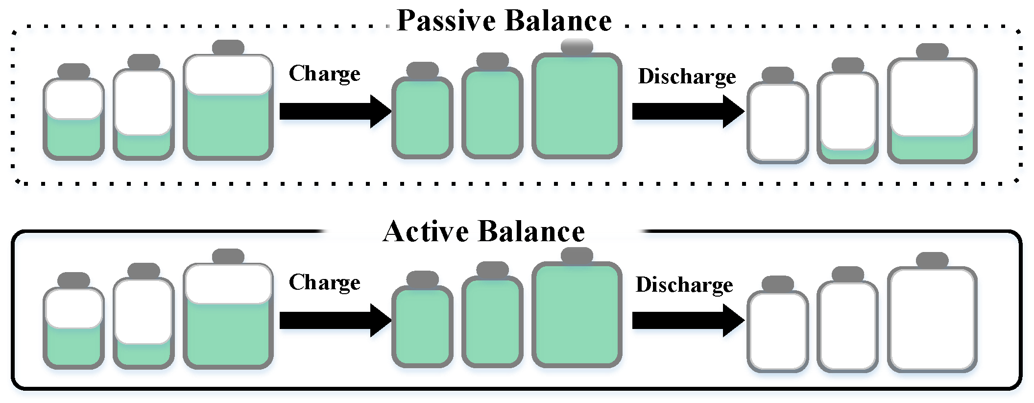
Figure 1. Passive balancing vs. active balancing methods.
Energies 12 03862 g001
Figure 2. Block diagram of the smart battery pack.
Energies 12 03862 g002
Figure 3. Schematics of the smart battery cell: (a) battery cell bypassed; (b) battery cell inserted.
Energies 12 03862 g003
Figure 4. Flowchart of the adopted balancing algorithm.
Energies 12 03862 g004
Figure 5. The balance process in the smart battery pack.
Energies 12 03862 g005
Figure 6. Normal distributions of cell capacities at the beginning of life (BoL) (σ = 1.5%) and after 3 years (σ = 3%).
Energies 12 03862 g006
Figure 7. Master application layer as a state machine.
Energies 12 03862 g007
Figure 8. New European Driving Cycle (NEDC) current profile.
Energies 12 03862 g008
Figure 9. SOC of the proposed smart battery pack (SBP) with a variation of 5% on the initial SOCs.
Energies 12 03862 g009
Figure 10. SOC of the cells in the battery pack with insets showing the situations at around 10% of the SOC: (a) passive balancing with cells at the BoL; (b) passive balancing with 3-year-old cells; (c) active balancing with cells at the BoL; (d) active balancing with 3-year-old cells.
Energies 12 03862 g010
Figure 11. Down-scaled experimental prototype.
Energies 12 03862 g011
Figure 12. Slave PCB board.
Energies 12 03862 g012
Figure 13. SOC balancing achieved by the proposed SBP. Each line corresponds to the SOC of one of the cells in the considered battery pack.
Energies 12 03862 g013
Figure 14. SOCs during discharging: (a) passive balancing; (b) proposed SBP with active balancing. Each line corresponds to the SOC of one of the cells in the considered battery pack.
Energies 12 03862 g014
Figure 15. (a) SOC in the master during communication loss; (b) output battery pack voltage.
Energies 12 03862 g015
Table 1. Useful capacities at the BoL and after 3 years with the passive and active balancing techniques.
Battery Pack with New CellsBattery Pack With 3-Year-Old Cells
Passive balancing51.57 Ah40.95 Ah
Active balancing54 Ah45 Ah
Table 2. Command execution status.
StatusStatus Code Description
000Not all slaves respond with the requested state of charge (SOC)
001All slaves respond with the requested SOC
010Not all slaves respond after 5 REQUEST_SOC or CMD packets broadcasted
011Not all slaves reply with valid data to a CMD packet
100All slaves reply with valid data to a CMD packet
101Not all slaves reply with valid data to an EXE packet
110All slaves reply with valid data to an EXE packet
Table 3. Operational hours at the BoL and after 3 years with the passive and active balancing techniques.
Battery Pack with New CellsBattery Pack with 3-Year-Old Cells
Passive balancing14.9 h12.2 h
Active balancing16.3 h13.8 h