Article

Experimental Investigation on the Effects of CO2 Displacement Methods on Petrophysical Property Changes of Ultra-Low Permeability Sandstone Reservoirs Near Injection Wells

1
State Key Laboratory of Petroleum Resources and Engineering, China University of Petroleum (Beijing), Beijing 102249, China
2
School of Petroleum Engineering, China University of Petroleum (Beijing), Beijing 102249, China
3
State Key Laboratory of Enhanced Oil Recovery, Beijing 100083, China
*
Author to whom correspondence should be addressed.
Energies 2019, 12(2), 327; https://doi.org/10.3390/en12020327
Submission received: 11 December 2018 / Revised: 3 January 2019 / Accepted: 18 January 2019 / Published: 21 January 2019
(This article belongs to the Special Issue CO2 EOR and CO2 Storage in Oil Reservoirs)

Abstract

:
The petrophysical properties of ultra-low permeability sandstone reservoirs near the injection wells change significantly after CO2 injection for enhanced oil recovery (EOR) and CO2 storage, and different CO2 displacement methods have different effects on these changes. In order to provide the basis for selecting a reasonable displacement method to reduce the damage to these high water cut reservoirs near the injection wells during CO2 injection, CO2-formation water alternate (CO2-WAG) flooding and CO2 flooding experiments were carried out on the fully saturated formation water cores of reservoirs with similar physical properties at in-situ reservoir conditions (78 °, 18 MPa), the similarities and differences of the changes in physical properties of the cores before and after flooding were compared and analyzed. The measurement results of the permeability, porosity, nuclear magnetic resonance (NMR) transversal relaxation time (T2) spectrum and scanning electron microscopy (SEM) of the cores show that the decrease of core permeability after CO2 flooding is smaller than that after CO2-WAG flooding, with almost unchanged porosity in both cores. The proportion of large pores decreases while the proportion of medium pores increases, the proportion of small pores remains almost unchanged, the distribution of pore size of the cores concentrates in the middle. The changes in range and amplitude of the pore size distribution in the core after CO2 flooding are less than those after CO2-WAG flooding. After flooding experiments, clay mineral, clastic fines and salt crystals adhere to some large pores or accumulate at throats, blocking the pores. The changes in core physical properties are the results of mineral dissolution and fines migration, and the differences in these changes under the two displacement methods are caused by the differences in three aspects: the degree of CO2-brine-rock interaction, the radius range of pores where fine migration occurs, the power of fine migration.

1. Introduction

Ultra-low permeability sandstone reservoirs have poor physical properties and high-water saturation, which makes them difficult to develop. Due to the significant oil displacement characteristics of CO2, the injection of CO2 into oil reservoirs for storage not only significantly increases the production of oil, but is also an effective means of controlling CO2 emissions to reduce the greenhouse effect. Among the displacement methods, CO2 flooding and CO2-WAG flooding are two common displacement methods used in oilfields, CO2-WAG flooding is superior to CO2 flooding in sweep efficiency and has a better effect on EOR, but the injection of fluid is more difficult [1,2,3,4,5,6,7,8,9]. However, no matter which displacement method is used, when CO2 is injected into the formation, a series of physical and chemical reactions (CO2-brine-rock interactions) are triggered, changing the physical properties of the reservoirs [10,11,12,13,14,15]. The changes in physical properties (porosity, permeability, mineral transformation, pore microstructure, pore size distribution etc.) seriously affect the flow of fluid in the ultra-low permeability reservoirs. Especially the long-term development of water injection before the injection of CO2 leads to the high-water saturation of the rocks around the injection wells, when CO2 is continuously injected into the wells, these reactions occurring in the near-well rocks where brine, CO2 and minerals are in full contact with each other are complete. Furthermore, compared with the rocks far from the injection wells the near-well rocks suffer large-flow scour form the fluid injected due to the radial flow, which provides the impetus for fines migration. Physical property changes in rocks caused by above factors damage the injection capacity of CO2 and brine, changing the concentrations and types of ions contained in fluids. Due to these interactions, the released fines migrate to the distant reservoir with the flow of fluid, which will cause serious damage to the reservoir and ultimately affect the efficiency of EOR and CO2 storage [16,17,18,19,20]. On the other hand, the in-situ multiphase flow characteristics in rocks under different CO2 displacement methods are different, and these also have different effects on physical properties changes. Therefore, precise knowledge of the physical property changes of the rocks near the injection wells and the differences in these changes after different CO2 displacement methods are the prerequisites for selecting the reasonable displacement method, and are also the focus of concern for oilfields, deserving further study.
In previous research, laboratory experiments were generally conducted under in-situ reservoir conditions as direct and reliable means to investigate the changes in the physical properties of sandstone reservoirs after CO2 injection. The changes in the rocks were analyzed and compared after the CO2–brine–rock interactions through X-ray diffraction (XRD), scanning electron microscopy (SEM), nuclear magnetic resonance (NMR), computed tomography scan (CT), mercury injection, etc. The contact modes between rock, CO2 and formation water during the experiments usually include carbonated water soaking, CO2 flooding, carbonated water flooding, CO2-WAG flooding [21,22,23,24,25,26,27,28]. The results of the studies above show that during the process of CO2 injection and CO2 storage in the reservoirs, the fines migration and carbonate precipitate caused by CO2-brine-rock interactions result in changes in rock minerals, permeability, pore structure, wettability and break the chemical balance of the formation water, ultimately affecting the seepage of multiphase fluid and threating to safety of CO2 storage.
However, the previous research focuses only on the changes in the physical properties of the reservoir after CO2 injection in a single method, there is no comparison of the changes after different CO2 displacement methods. Moreover, the core permeabilities used in the most of displacement experiments mentioned above are relatively large (1–500 mD). The research performed on unconventional and ultralow permeability reservoir rocks mostly focuses on safety of CO2 storage, evolution of permeability and mineral composition during CO2 storage in saline formations rather than the injection stage. Rock samples in these experiments are usually just placed in brine saturated with CO2 for a long periods time instead of being displaced by fluids. Research on the effects of displacement methods on physical property changes in ultra-low permeability sandstone reservoirs are rare. At the same time, to make the results of several groups of experiments comparable, the cores used in all experiments must have the same or similar initial physical properties, which is ignored in previous studies. In addition, the experimental process will cause irreversible changes in the core physical properties, and the cores are no longer sensitive to CO2 after fully reacting with CO2 and formation water [12], the same core cannot be reused in multiple groups of flooding experiments, which increases the difficulty of design the scheme of comparative experiments.
The main objectives of this study are to investigate the changes in physical properties of the cores with high water saturation from Huang 3 ultra-low permeability sandstone reservoirs (Chang Qing Oilfield, Shaanxi Province, China) after CO2 flooding and CO2-WAG flooding and assess the difference in damage to the reservoir between the two displacement methods, providing data support for numerical simulation and screening of displacement methods. First of all, a core sample was cut into three pieces, then the three short cores were analyzed by SEM, XRD, NMR, gas porosity and permeability tests before the experiments to verify the similarity of the initial physical properties. Afterwards, brine (control group), CO2 and CO2-WAG flooding experiments were separately conducted on the three cores saturated by brine under simulated formation conditions (78 °C, 18 MPa). Then the changes in permeability, porosity, pore microstructure and pore size distribution of each core before and after flooding were compared, and the difference in these changes of the three cores were analyzed. Finally, the mechanism of the above physical property changes and the reasons for the differences under different displacement methods are clarified.

2. Experimental Section

2.1. Experimental Materials

The rock sample, named HU-24, used in this experiment is provided by the Research Institute of Petroleum Exploration & Development (RIPED, Beijing, China) and is taken from the Huang 3 formation of the Chang Qing Oilfield in the Ordos Basin in western China. The Chang Qing Oilfield is a typical ultra-permeability and low-producing oilfield, the target oil reservoir Huang 3 in this study is one of the main production layers, CO2 injection is planned to be implemented for EOR in the next stage of production after brine injection. The Huang 3 reservoir has a good continuous distribution, the pores are mostly primary intergranular, and the particles are well sorted, the basic parameters of the reservoir are provided by the RIPED (Table 1). The main minerals contained in the rocks of the reservoir are quartz, feldspar, rock debris and pore filler, classified as clasolite. In order not to interfere with the experimental results, the cores used in the experiment are taken from the area without CO2-EOR operation to ensure that no CO2-brine-rock interactions have occurred in the rock. The cores were cleaned by toluene and methanol (removing inorganic salts and hydrocarbons) and dried for 24 h under the temperature of 30 °C in an oven. High-purity CO2 (99.99%) was used in this study. The brine used in the core-flooding experiments was prepared based on formation water data provided by the RIPED (Table 2).

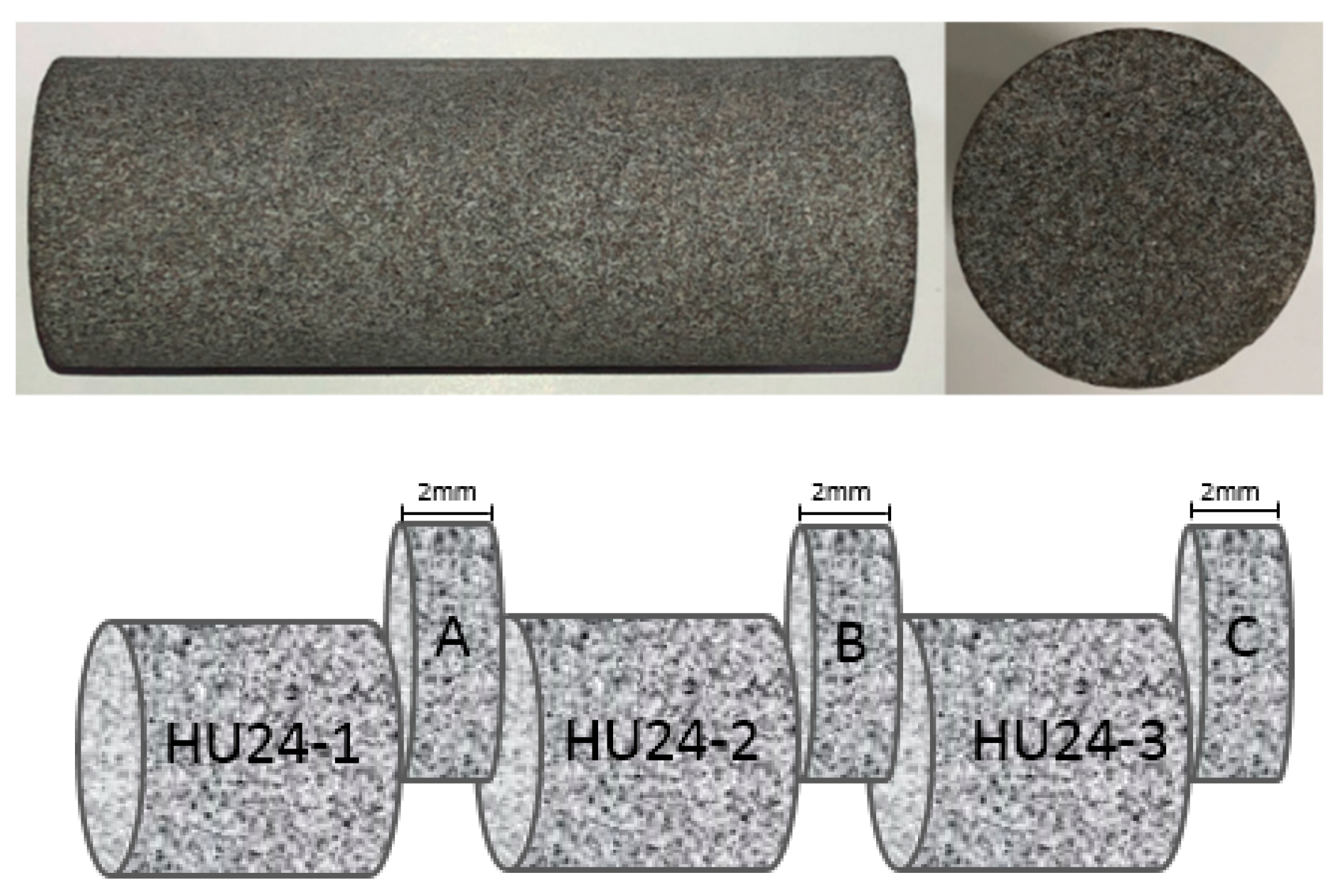
2.2. Core Segmentation and Analysis

In order to obtain three cores with the same physical properties for the three groups of flooding experiments, the homogeneous core sample HU24 without bedding was cut equally into three sections (Figure 1), numbered HU24-1, HU24-2 and HU24-3. Due to the destructive detection (SEM, XRD) on the three cores, a slice of 2 mm in thickness was cut from each core as sample to be measured, respectively numbered A, B, C. After that, some measurements were taken to confirm that the three cores had the same physical properties, at the same time, obtaining the parameters of the cores before the flooding experiments to compare with that after the flooding.
The core plugs HU24-1, HU24-2 and HU24-3 were cleaned again to remove the movable particles produced during the segmentation process and dried by the previous operation. Then the porosity and permeability of the core plugs were measured by the high-pressure helium permeameter-porosimeter (TEMCO, lnc., Tulsa, OK, USA), this measurement was repeated three times to obtain accurate results on each core plug (Table 3).
The measurement results show that the permeability and porosity of the three cores are close to that of the original core. Among them, the permeability of cores HU24-2 and HU24-3 have more similar permeability and porosity.
The pore size distribution of the core was measured by Nuclear Magnetic Resonance High Temperature and Pressure Seepage Analysis Analyzer (Mini-MR, Niumag, Suzhou, China) in this paper, the magnetic intensity, gradient value control precision and frequency range of the NMR apparatus are 0.5 T, 0.025 T/m, 0.01 MHz and 1–30 MHz, respectively. Before the measurement, the cores were completely saturated with brine under vacuum for 48 h and were compared with the weight of dry core to calculate the volume of the brine entering the core pores. This spin-echo method records the pore size distribution, similar to mercury porosimetry, using the transverse magnetic relaxation time.
During the MNR tests, the T2 and magnetization of the hydrogen nuclei of the fluid in all core pores are recorded to obtain the T2 spectrum (Figure 2). Since the amplitude of transverse magnetization is proportional to the number of hydrogen nuclei and the value of T2 is determined by the size of the pore space in which the hydrogen nuclei are located, different pore sizes in fluid saturated rocks will produce characteristic T2 distributions. In the T2 spectrum, there is a one-to-one match between the T2 value and the pore size, the larger the T2, the larger the pore radius corresponding to it, and there is a coefficient that allows these two values to be easily converted to each other. The amplitude of the magnetization signal represents the proportion of the pore distribution, and the larger the signal amplitude, the higher the proportion of the pore distribution. Therefore, the changes in T2 distribution represent the changes in pore size distribution of the core. Since the signal measured in MNR measurement is the T2 of the hydrogen nuclei contained in the water in the pores, if some of the pores are not saturated with brine, then their characteristics in the T2 spectrum will be missed. In order to compare the changes in pore size distribution through T2 spectrum, the premise is that the brine saturation of the cores must be the same and the cores are saturated enough [29]. According to Equations (1) and (2), the T2 is converted into pore radius value [30]. In Formula 2, a and b are the empirical parameters, and the value of C is calculated according to the values of a and b provided by Fang:
T2 = C·r
C = a·eb√ΦK
where T2, ms; r pore radius, μm; C conversion coefficient, 27.52 ms/μm in this paper
Before the flooding experiments, the T2 spectrum of the three cores have the same shape and a high coincidence degree, demonstrating that the pore size distributions of the three cores are relatively close.
Broken pieces with fresh surface taken from the samples (A, B, C) were observed by the Field Emission Scanning Electron Microscope (Model: SU8010, Maximum resolution: 1.0 nm, 15 KV, Hitachi, Tokyo, Japan). The samples were vacuum-plated with carbon before the observation for the clearer pictures. The microstructure of some pores in the cores before the flooding experiments was observed.
At last, the rest of the samples A, B, C were analyzed by XRD (Model: D8 Focus, Angle range: 0–130 degrees, Bruker, Billerica, MA, USA). The results of XRD (Table 4) show that the average mineral contents of these three samples are very close, demonstrating that all kinds of minerals are evenly distributed in the core HU24. Therefore, these three cores HU24-1, HU24-2 and HU24-3 are considered to have similar mineral contents.
The measurements above show that the basic physical properties of the three cores are relatively close, especially the cores HU24-2 and HU24-3 in terms of porosity, permeability and pore size distribution. Therefore, the CO2-WAG flooding and CO2 flooding were conducted on core HU24-2 and core HU24-3, respectively. However, as a comparison, the core HU24-1 only underwent flooding experiment with brine.

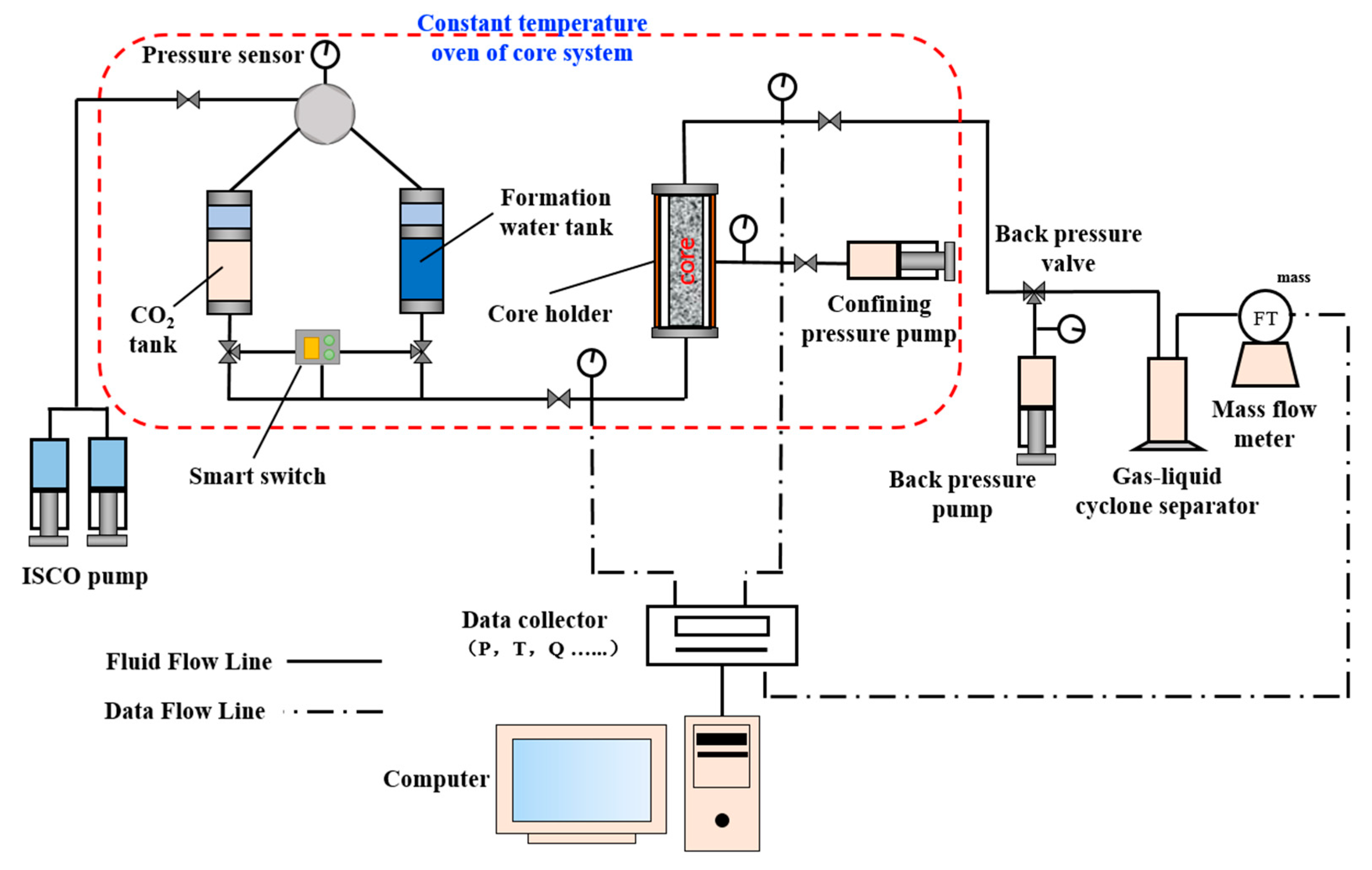
2.3. Experimental Equipment

Figure 3 shows the schematic diagram of the experimental apparatus, it mainly consists of a constant temperature oven, two tanks (1000 mL), three constant flow pumps (260D, ISCO, Lincoln, NE, USA)—one pump for injection, two others for confining pressure control and back pressure control—a core holder, seven pressure sensors, a gas-liquid cyclone separator, a mass flow meter, a data collector, smart switch and a computer. During CO2-WAG flooding, the valves of CO2 and brine need to be frequently switched, and the smart switch is set to automatically perform this work. At the same time, it should be noted that the core holder is placed vertically to eliminate the effect of gravity segregation. Finally, all the experimental components were connected with stainless steel tubing (D = 1 mm) and were put the parts that needed to be heated into the constant temperature oven.

2.4. Experimental Procedure

2.4.1. Experimental Preparation

The three core samples were continuously evacuated for 24 h and saturated with brine for 24 h. At the meantime, CO2 and brine were separately put into the corresponding container. Then the temperature of the constant temperature oven core system was set to 78 °C and the outlet pressure of the core was steadily controlled at 18 MPa by the back-pressure valve and back pressure pump according to the P-T conditions of the formation reservoir. The flooding experiments could only be carried out after 24 h to ensure that all parts in the constant temperature oven were heated to 78 °C.

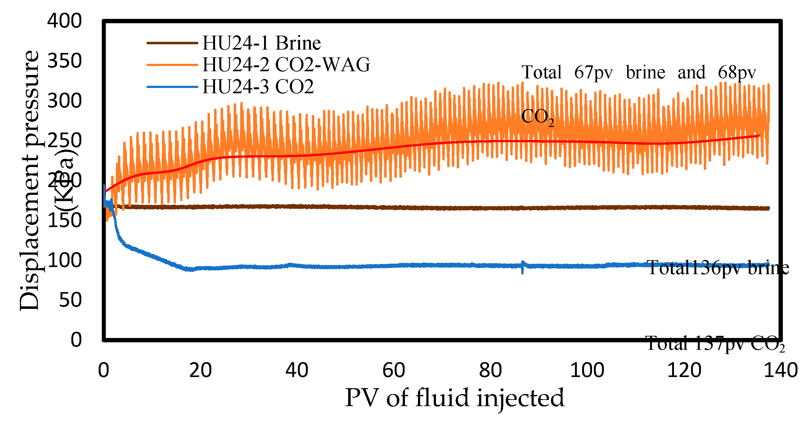
2.4.2. Core-Flooding

Firstly, the core sample HU24-3 was put into the core holder and flooded by brine for 3 pore volume (PV) to ensure the core was completely saturated with brine. To avoid excessive effective stress which would cause damage to the core pore-throat structure and interfere the experimental results, the confining pressure slowly increased with the increase of inlet pressure until the effective stress on the core reached reservoir net effective stress. After that, the core began to be flooded by CO2 and the injection flow rate of the was set to 1 mL/h in in order to avoid the damage of velocity sensitivity to the core. The flooding continued until the pressure at the outlet and inlet were stable (which meant the structure inside the core did not change in the short term) and the total flooding time was at least 150 h [22,25].
After the core-flooding of the core HU24-3, the core in the holder was replaced by HU24-2. The core HU24-2 was flooded by CO2 and brine in the way of CO2-WAG. The volume ratio of water slug and CO2 slug is 1:1, the volume of the slug is 0.4 PV. According to the comprehensive assessment, these injection parameters are considered to be optimal for the effect of oil displacement and injection capacity, commonly used in oilfields [31,32,33]. When the inlet pressure remained stable during CO2 injection in the three consecutive flooding cycles and the total flooding time was over 150 h, the core-flooding was completed. Produced brine at outlet was collected and the chemical components in brine were detected during the flooding. Finally, HU24-1 was flooded only by brine in the same way above at the same conditions.

2.4.3. Measurements after Flooding

When the flooding experiment was completed, the core was dried and measured for permeability and porosity values. Afterwards, the core was evacuated to saturate brine for NMR measure to obtain the T2 spectrum. Then mercury injection was carried out on a dry cylinder (with the length of 1cm and the diameter of 2.52 cm, the same as the core) taken from the same position on the inlet of each core to analyze the pore size distribution. Finally, the pore microstructure was observed through the rest parts of the three cores by SEM, 8–10 observation samples were taken from each core and five observation points were selected from each observation sample, and the observation points on each sample were relatively large pores which had obvious characteristics and were easy to be recognized under SEM. Then, these remaining core fragments were tested by XRD.

3. Results

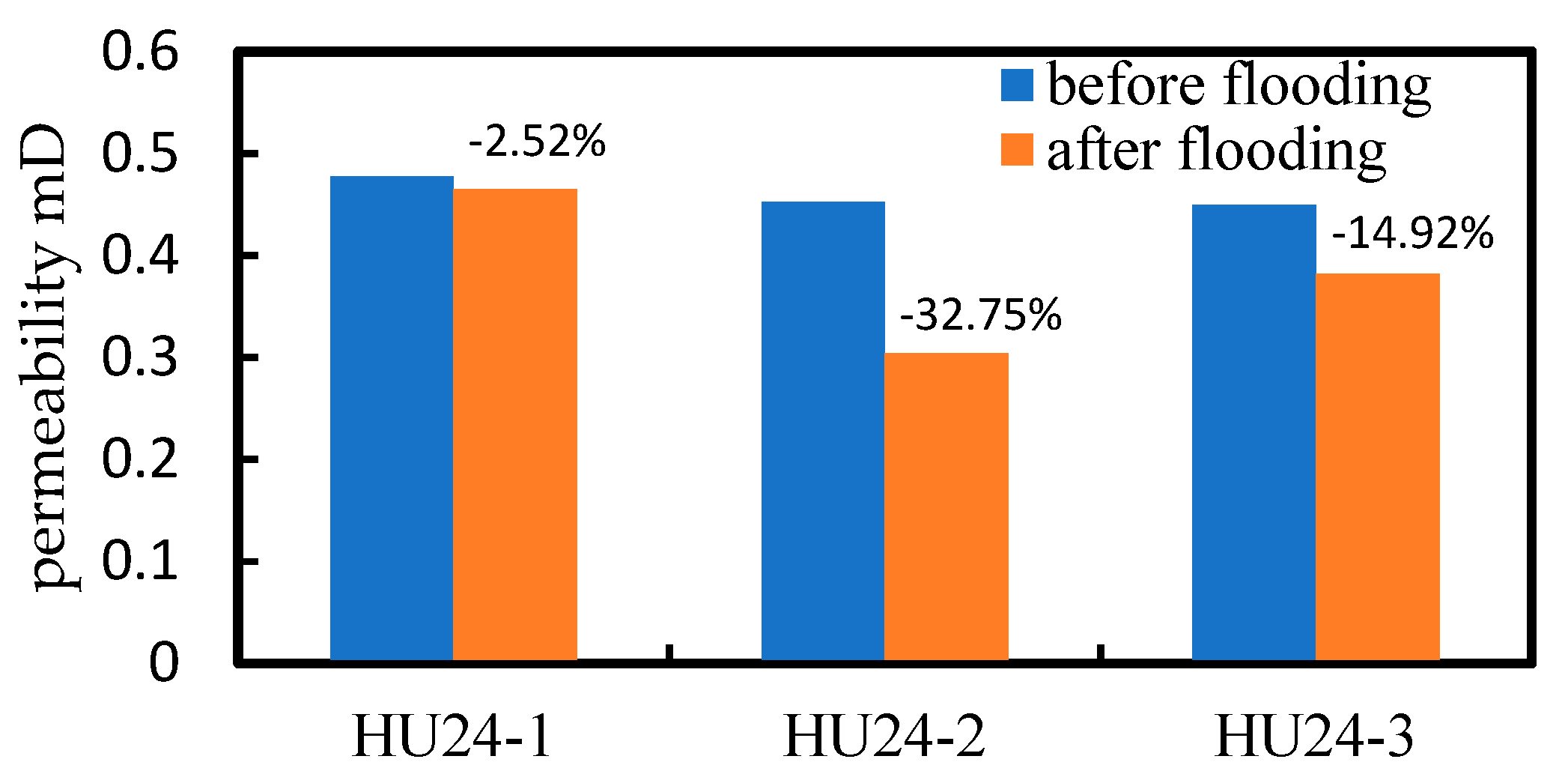
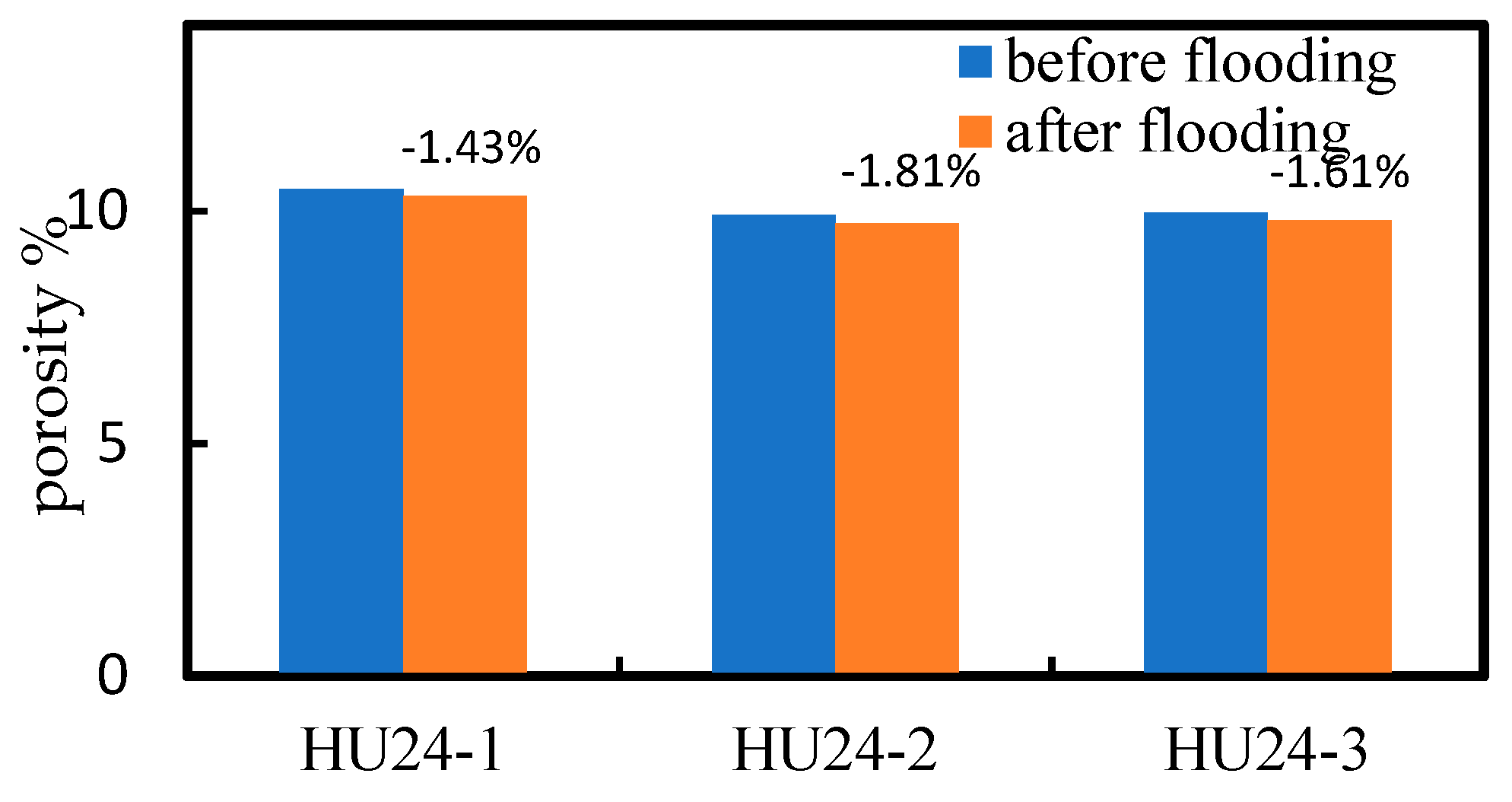
3.1. Porosity and Permeability

The changes in porosity and permeability of the core samples before and after the flooding experiments are shown in the Table 5. There is a slight decrease (2.52%) in permeability in the core HU24-1 after brine flooding.
However, HU24-2 and HU24-3 show significant decrease in permeability after flooding, the permeability of core HU24-2 decreases the most (32.75%) after CO2-WAG flooding, and the permeability decline of core HU24-3 (14.92%) after CO2 flooding is less than that of core HU24-2 (Figure 4). In contrast to these, the reduction in porosity of the three cores after flooding is less than 2% (Figure 5) (basically within the uncertainty of the measurements). The trend of displacement pressure (Figure 6) also reflects the trend of permeability change to some extent.
During the flooding process, the displacement pressures of core HU24-2 and HU24-3 increase slowly, and the displacement pressure of core HU24-2 increases significantly compared with that of core HU24-3.

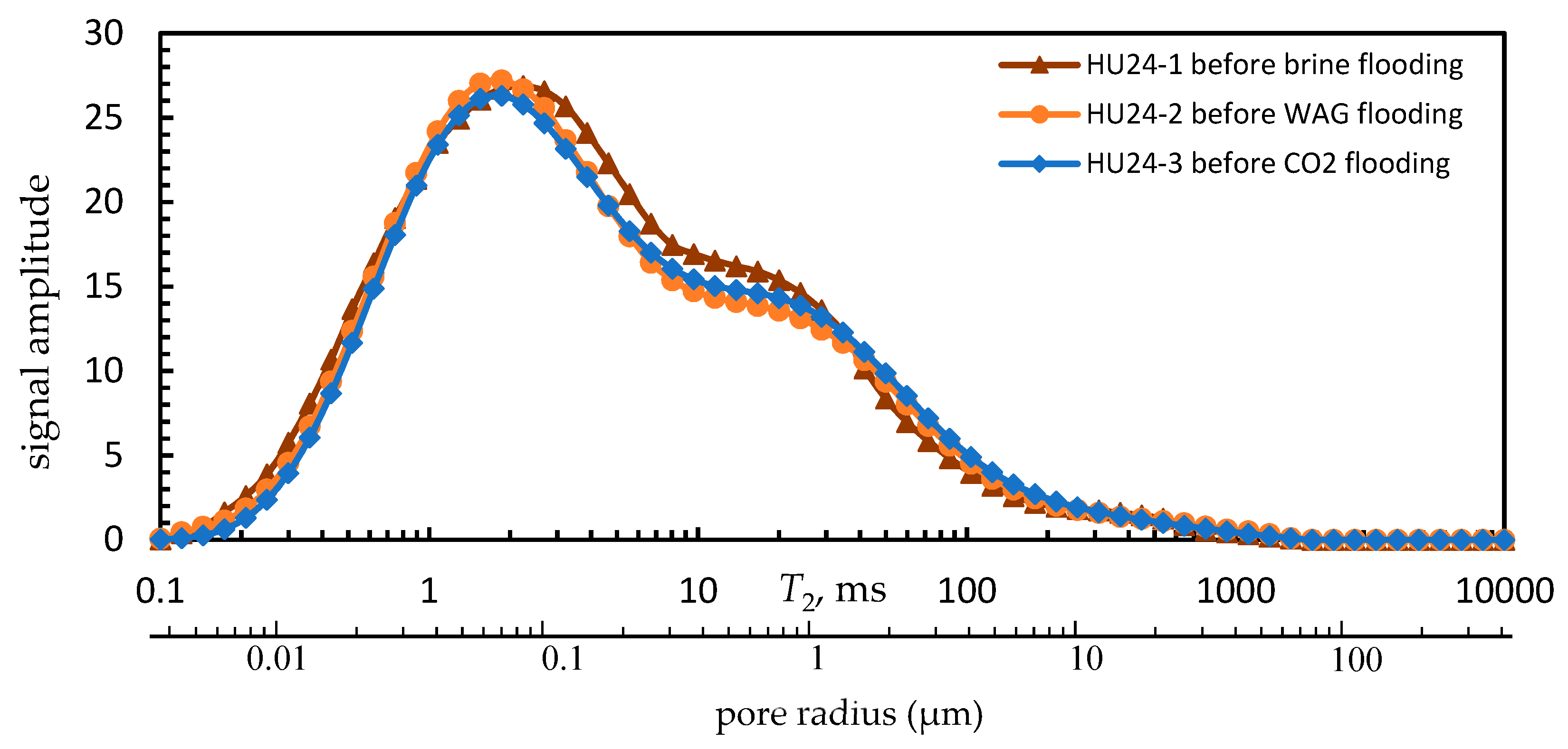
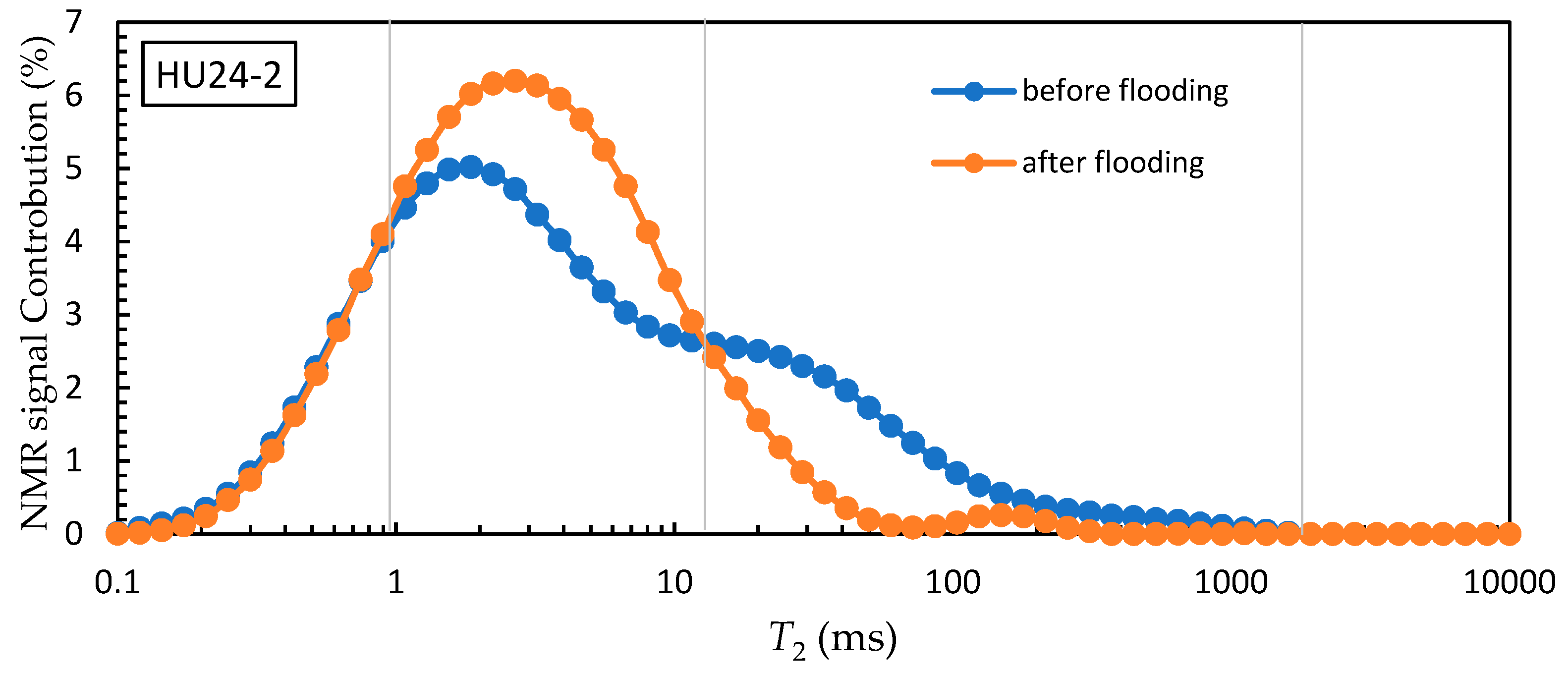
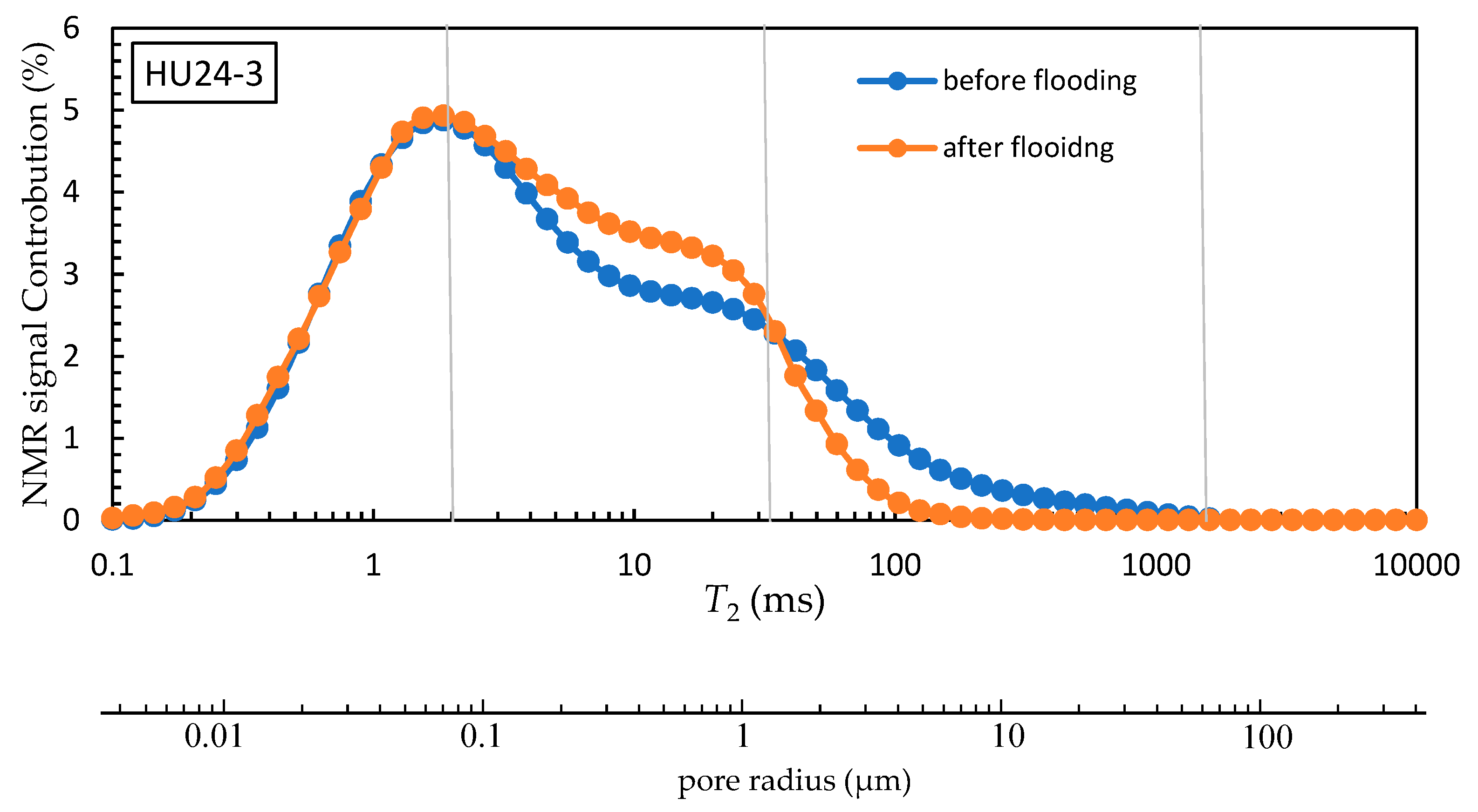
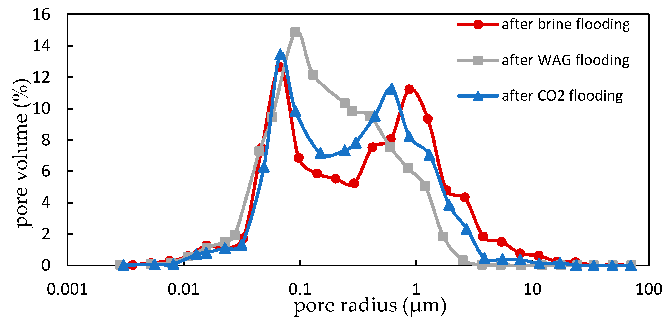
3.2. Pore Size Distribution

The brine saturations of cores (Table 6) satisfy the premise of NMR measures mentioned above, indicating that the NMR results are reliable. In addition, the signal amplitude is normalized to obtain the pore radius distribution of the cores (Figure 7 and Figure 8).
Figure 7 shows that the T2 spectrum of the core HU24-1 is highly overlapped before and after the brine flooding, indicating that the pore size distribution of the core HU24-1 is almost unchanged after the flooding. After injection of CO2, the NMR T2 spectrum of the cores HU24-2 and HU24-3 shift to the left, the proportion of pores with large radius in right of the spectra decreases, the proportion of pores with medium radius in the middle of the spectra increases, while the proportion of small pores remains almost unchanged.
Comparing the T2 spectrum of the cores HU24-2 and HU24-3 before and after the flooding experiments (Figure 8), although the trends of changes in the pore size distribution of the two cores are similar, the range and amplitude of the changes in pore size distribution of the core HU24-2 are larger than that of the core HU24-3 (Table 7). The pore size distribution of the core HU24-2 is more concentrated after the flooding. In core HU24-2, the shape of the T2 spectrum almost changes from the double peak before flooding to the single peak after flooding. However, the shape of the T2 spectrum of the core HU24-3 after flooding is still a double peak, and only the width of the double peak narrows down.
The difference in the pore size distributions of the three cores after flooding as shown in the mercury injection test results (Figure 9) are similar to that expressed in the T2 spectrum, especially the distribution of large pores. However, compared with the T2 spectrum, the mercury injection test results show that the proportion of large pores is relatively large, while the proportion of small pores is relatively small, these are probably due to that the average maximum mercury saturation in the three cores during the mercury injection process is 91%, and it is difficult for mercury to enter the tiny pores.

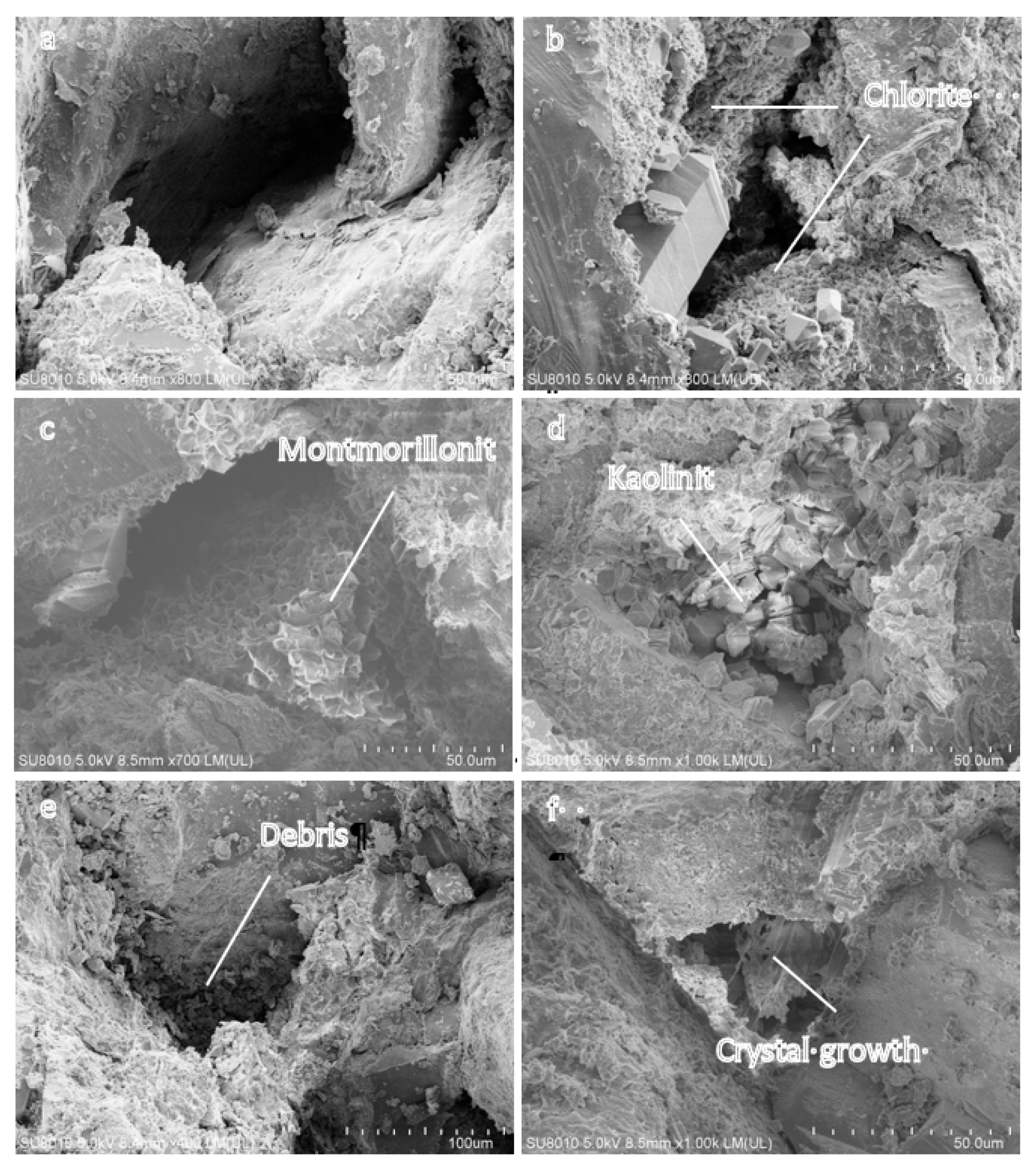
3.3. Pore Microstructure and Rock Minerals

According to the results of SEM observation, the microstructure and filling condition of the pores are divided into two categories: the first category of pores are mainly contained (Figure 10a–c) in the cores before flooding and the core HU24-1 after the brine flooding, the walls of some large pores observed are smooth, and there are few filling materials (Figure 10a) in these pores, while in some of this category of pores, there are alveolate montmorillonite, fluff sphere-like chlorite and very small amount of book-like kaolinite distributed on the walls, but these clay minerals tightly align, which occupy little void space and do not block the pores and throats (Figure 10b,c), the microstructure of such pores is characterized by clear and unobstructed connectivity between the pores and the throats, there is sufficient space in the pores, causing relatively slight resistance of the fluid flowing in the pores; The other category of large pores (Figure 10d–f) mainly contained in the core HU24-2 after CO2-WAG flooding and the core HU24-3 after CO2 flooding are filled with scattered sheet kaolinite, debris and precipitates growing, and some of these pores are filled to a very serious extent, which reduces the space volume of these pores or blocks the throats, leading to poor connectivity between pores and throats (Figure 10d,e). Furthermore, salt crystals form bridging blockage in the pores (Figure 10f), such pore microstructure is detrimental to permeability of the cores [34].
In addition, comparing the SEM observation results of the core HU24-2 and HU24-3 after flooding, it is concluded that the fillers in the pores of the core HU24-2 are mostly loose flake kaolinite and debris, and the salt-bridge blinding are rare. In the core HU24-3, the situation is the opposite, the proportion of the pores blocked by salt bridge is relatively large among the large pores blocked. Overall, the large pores in the core HU24-2 are blocked to a greater extent than that in the core HU24-3, moreover, the amount of large pores blocked in the core HU24-2 is larger.
With the changes in pore microstructure, changes in rock mineral contents occur in these cores after the flooding experiments (Table 8). The contents of minerals in the cores HU24-2 and HU24-3 change significantly, especially, the contents of K-feldspar and carbonate minerals (mainly including Calcite and Dolomite) decrease, while the content of clay minerals increases. Furthermore, these changes are more pronounced in the core HU24-2.
In summary, there is no significant change in physical properties of the core HU24-1 including permeability, porosity, pore size distribution and pore microstructure after only brine flooding. Compared with the core after CO2 flooding, the core after CO2-WAG flooding has more severe changes in microstructure of large pores, which corresponds to the more significant changes in pore size distribution and the greater decrease in permeability showed on entire core scale in the core HU24-2.

4. Discussion

4.1. Physical Property Changes

4.1.1. Permeability Decline and Fines Migration

The experimental results of core HU24-1 indicate that the injection flow rate do not induce velocity sensitivity, and the brine do not cause the expansion of clay minerals under the experimental conditions, eliminating the interference of brine on the experimental results during the flooding process. The permeability of the cores HU24-2 and HU24-3 decrease after flooding, but the porosity is unchanged, which is similar to the results of previous experiments [9,15,19,35,36,37,38]. Those studies believe that CO2 is injected into the core and dissolved into brine to form carbonic acid, which triggers CO2-brine-rock interactions. The dissolution of carbonate cements and feldspar in the matrix causes the movable fines to be released. The migration of these fines and the precipitation of new minerals due to the change in pH of the fluid in the pore lead to blockage in pores during the flooding process, eventually causing the decline of rock permeability [22,25,39,40].
Compared with previous experiments, the cores used in the experiments of this paper have lower initial permeability, and the decrease of permeability is more obvious after the flooding still with little change in porosity, which is consistent with the characteristics of fines migration in the core. The migration of fines detached from the core does not cause a significant reduction in the total pore volume, but the fines accumulate at the pore throat and formed blockages, which significantly reduce the fluidity of fluids in the flow channels inside the rocks [7]. Although the dissolution of minerals and fines release can lead to an increase in pore volume during the flooding process, which increases the rock permeability to a certain extent, the experimental results indicate that under the experimental conditions in this paper, especially in the ultra-low permeability cores with smaller pore throat structure, compared with the blockage caused by fines migration, the increase in permeability caused by mineral dissolution does not predominate, with the change in porosity caused by mineral dissolution is also not obvious.
According to the experimental results, the changes of permeability and porosity are the macroscopic manifestation of the changes of physical property. The changes in microstructure of pores and the resulting changes in pore size distribution of the cores are the microscopic mechanisms of the decline of rock permeability.

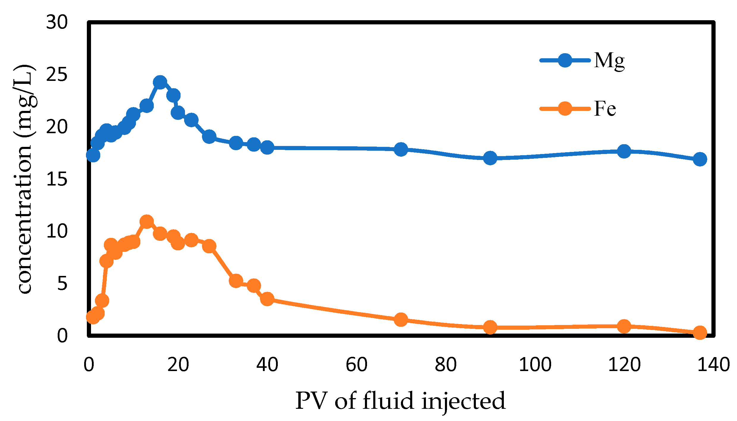
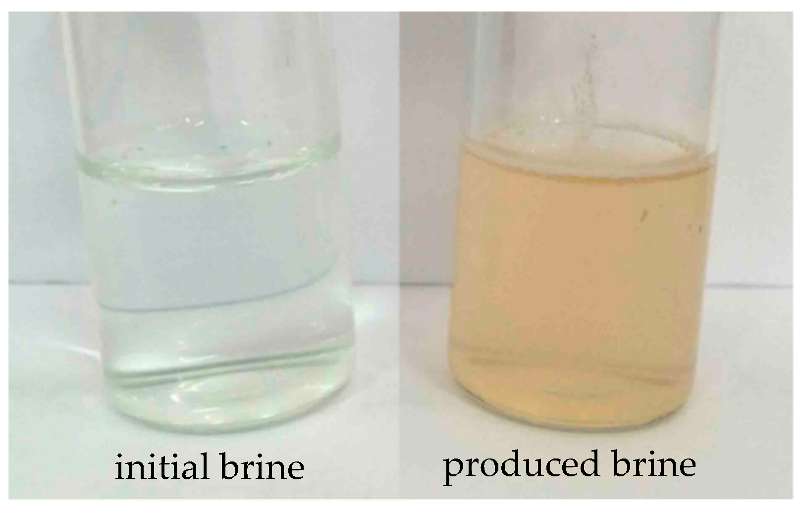
4.1.2. CO2-Brine-Rock Interactions

The comparison between the two categories of pore microstructure indicates that during the long-term injection of CO2 in two ways of displacement, the original compact structure of the authigenic clay mineral in the core is destroyed, and the exfoliated or newly generated clay mineral fragments loosely adhere to pore walls and accumulate in the pores [12,18]. At the same time, debris are released and migrate with the fluid, finally depositing in the fluid flow path. The salts in the fluid in the pores are precipitated and form bridge blinding.
These changes in pore microstructure are caused by CO2-brine-rock interactions and fluid displacement. According to the obvious changes in mineral contents of the cores (Table 9), reactions occurring in sandstone rocks generally include dissolution of carbonate minerals, K-feldspar, clay mineral and the precipitation of neogenic mineral (Equations (3)–(7)) during the CO2 injection process [12]. The concentration of Mg2+ and Fe3+ in produced brine also reflects the relatively sufficient CO2-brine-rock interactions in the core HU24-2 in the early stage of flooding, and the trend of concentration change is gentle in the later stages (Figure 11). Under high temperature and high pressure, potassium feldspar dissolves in the acidic environment, kaolinite is generated during the reaction and released from the rock matrix. The carbonate minerals as the cement can react rapidly with carbonic acid, then the stability of the mineral particles in the pores is destroyed, and the debris fines are released, causing massive fines migration. On the other hand, the dissolution of carbonate minerals can also lead to an increase in the concentration of Ca2+, Mg2+ and other ions in the fluid, once the external conditions such as concentration, pH, temperature, or pressure change, these ions are very likely to reprecipitate (CaCO3, MgCO3), which also causes blockages in the pores [40]. The Fe2+ released during this process and oxidized by air at outlet causes the produced brine to appear pale yellow (Figure 12). In addition, clay minerals are very sensitive to changes in the surface chemical and physical environment. Supercritical CO2 can diffuse into the clay minerals and change the charge between the clay mineral layers causing repulsive force, which destroys the stability of the layer structure and finally results in the dispersion of clay minerals [41,42]. The interaction between clay minerals, CO2 and brine even can transform clay minerals into other kinds of clay minerals, dispersed authigenic clay minerals and released neogenic clay minerals become movable fines. Therefore, the dissolution of carbonate minerals and changes in clay minerals cause changes in pore microstructure in a relatively short period of time. When various types of fines migrate with the fluid in the pores, the throats are preferentially blocked, and the connectivity between the pores and the throat is the key factor affecting the core permeability. The fines from this pore or nearby pores then continue to accumulate at the throats and pores, causing changes in pore size (Figure 13c,d).
K-feldspar:
2KAlSi3O8 + 2H+ + 9H2O = Al2Si2O5(OH)4(kaolinite) + 2K+ + 4H4SiO4
Chlorite:
[Fe/Mg]5Al2Si3O10(OH)8 + 5CaCO3 + 5CO2 = 5Ca[Fe/Mg](CO3)2 + Al2Si2O5(OH)4(kaolinite) + SiO2 + 2H2O
Carbonate minerals:
CO2 + H2O + CaCO3 ⇌ Ca(HCO3)2
CO2 + H2O + MgCO3 ⇌ Mg(HCO3)2
CO2 + H2O + FeCO3 ⇌ Fe(HCO3)2
Regarding the growth of salt crystals, previous studies have shown that when the acidic formation water is extracted to the mineral surface under capillary pressure and fully exposes to supercritical CO2, then salt crystals precipitate [43]. In this paper, especially in the core flooded by CO2, salt bridge blinding is found in a certain number of large pores, which not only divides pore space into multiple parts, but also blocks the flow of fluid in the pores.
The changes in pore microstructure caused by the above reasons seriously impair the permeability of the ultra-low permeability rock under the premise of less effect on the overall porosity of the rock. In particular, the microstructure of large pore with great contribution to permeability has obvious changes as shown in SEM photograph, so the proportion of large pores declines significantly in pore size distribution [44].

4.1.3. Pore Size Transformation

The T2 spectrum indicate that the pore size distribution changes after the injection of CO2, however, there is no significant change in the total pore volume, which represents there are mutual transformations among the pores with different sizes in the core [12,25]. The main occurrence in this paper is the transformation of large pores to medium pores. According to the changes in pore microstructure, changes in the proportion of the pores with a certain radius value is considered to be caused by two factors. On the one hand, during the process of mineral dissolution, fines release (enlarging pore space) and fines migration, pore blockage (reducing pore space), the pores are transformed into pores with other sizes. On the other hand, pores with other sizes are also transformed into pores with this radius for the same reasons, and the two opposite transformations jointly determine the change in proportion of the pores with this radius. However, the probability and tendency of transformation of pores with different radii are different. During flooding, CO2 is the non-wetting phase and mainly exists in large pores, these pores as main flow channel are the main place where the fines migration occurs. Fines from different pores have high probability of accumulating in large pores, which blocks pores and makes the pore size measured by NMR decrease. In large pores it is obvious that the effect of fines migration is greater than that of mineral dissolution. So, the large pores tend to transform into small ones during the flooding process [45] (Figure 13c,d). Although the medium pores may also be transformed into pores with other sizes, resulting in a decrease in the proportion, according to the experimental results, it is apparent that this decrease is less than the increase in the proportion due to the transformation of the large ones. For the smaller pores (for example, radius < 0.036 μm in core HU24-2), the fluid in these pores is considered to not flow during the flooding process and there is no fines migration. These pores have little opportunity of transformation.
In summary, after the injection of CO2, the changes in permeability, pore size distribution and pore microstructure are consistent and there are intrinsic connections among these changes. The common mechanism of physical property changes are mainly minerals dissolution and fines migration, which mainly are summarized as three elements: the generation of transportable fines, the place where fines migrate, and the fluid carrying fines. Among them, the amount of transportable fines are determined by the CO2-brine-rock interactions in the core. For the core with certain pore size distribution, the method of displacement and the type of injected fluid determine the other two elements. The three factors above ultimately determine the degree of physical property changes in the rocks.

4.2. Differences in Physical Property Changes

Since the consistency of the initial properties of the three short cores used in the experiment is verified before the flooding, after the experiments the difference in the changes in cores physical properties can only be caused by the different displacement methods. According to the displacement characteristics and the mechanism of the changes in core physical property mentioned above, there are three main reasons for the differences in physical property changes under different displacement methods: the extent and scope of the CO2-brine-rock interactions, the radius range of pores where fine migration occurs, the driving force of fine migration.
Firstly, the CO2-brine-rock interaction is the cause of movable fines generation and the precondition for the rock physical property changes. Under the premise of eliminating the factors such as velocity sensitivity and expansion of clay minerals, there is almost no movable fine in the core HU24-1 during the flooding process, so the physical properties are basically unchanged. However, in the core HU24-2 and HU24-3, there are great difference in the extent and scope of the CO2-brine-rock interactions during the flooding process. During CO2 flooding, part of the brine in the large pores is preferentially driven out, CO2 mainly exists in the center of large pores, and the remaining brine in these pores appears in the form of water film [46]. In addition, the entry of CO2 into the smaller pore space mainly depends on the diffusion in brine, and the diffusion rate in the porous medium is slow. Therefore, the amount of formed carbon acid is small with the relatively light degree of mineral dissolution in the core. At the same time, there is a relatively large amount of supercritical CO2 in the core HU24-3, the growth of salt crystals and the destruction of the original compact structure of clay minerals dominate in the large pores, which results in small amount of released fines. However, the core HU24-2 is continuously replenished with CO2 and brine during CO2-WAG flooding, the contact between CO2, brine and mineral is more sufficient, and the degree of CO2-brine-rock interactions is relatively large in the core. In addition, the CO2-WAG displacement has the effect of expanding the sweep area of CO2, CO2 can enter smaller pores under the action of displacement pressure. Therefore, there are more pores where CO2-brine-rock interactions occur. For the above reasons, larger scales of transportable fines are produced in the pores of core HU24-2 during the flooding (Figure 13a,b).
Secondly, in terms of the radius range of pores where fines migrate, compared with CO2 flooding, fine migration occurs in more pores with different radii in the core during CO2-WAG flooding. As the water saturation decreases during the CO2 flooding, CO2 gradually becomes the continuous phase and flows in the large pores, and the fine migration and blockage mainly occur in these pores. However, during the process of CO2-WAG flooding, when the CO2 flooding period is over in a cycle, the CO2 mainly retaines in the large pores, and when the subsequent brine flooding is carried out, the flow of the fluid in the large pores is hindered due to the influence of the Jamin effect ,which means the additional resistance effects when droplets (drops or bubbles) in two-phase percolation of liquid-liquid or gas-liquid pass through the pore throat or narrow pores [47,48], then the brine with CO2 dissolved in flows in the relatively small pores, and the fine migration and blockage would also occur in those smaller pores, resulting in the changes in microstructure and size in more pores (Figure 13a,b).
Finally, the power of fine migration during CO2 flooding is weaker than that during CO2-WAG flooding. The fluid of long-term flow in the pores is CO2 during CO2 flooding, while the CO2 with low flow rate has a weak ability to carry fines [49]. The migration of fines mainly depends on the liquid film on the pore surface or the small amount of flowing brine. During CO2-WAG flooding, the main fluid carrying fines is brine, and the ability of liquid to carry fines to migrate is much greater than gas. Furthermore, the pressure fluctuation generated during the switch of gas-water injection exacerbates the release and migration of fines [50].
In conclusion, it is based on the difference in the three aspects above that there is difference in physical property changes under the three displacement methods.

5. Conclusions

In this paper, the displacement experiments are conducted on ultra-low permeability sandstone cores with similar physical properties to study the changes in physical properties of the high water cut rocks and the difference between these changes after CO2 flooding and CO2-WAG flooding.
The experimental results indicate that after being flooded by CO2 in different ways, the core permeability decrease with the almost unchanged porosity, some pores of the rock are blocked by debris fines, clay minerals and salt crystals, and the pore size distribution curve shift to the left. The phenomenon of mineral dissolution caused by CO2-brine-rock interaction and the pore blockage caused by fines migration are considered as the causes of these changes.
The decline of permeability after CO2-WAG flooding is larger than that after CO2 flooding, the degree of pore blockage and the variation of the pore size distribution in the former are more serious. The reasons for the difference in physical property changes are divided into three aspects: the reaction is more sufficient and more fines are released during CO2-WAG flooding; the radius range of pores in which fine migration and blockage occur is wide during CO2-WAG flooding; the power of fine migration is weak during CO2 flooding.
CO2-WAG flooding is more damaging to the permeability of the near-well reservoir than CO2 flooding at the same injection rate, which greatly increases the difficulty of injecting fluid into the reservoir. Therefore, with reference to this factor, the CO2 flooding should be selected as much as possible in the reservoir. If CO2-WAG flooding is selected in order to obtain a better sweep efficiency of the injected fluid, measures should be taken to protect the near-well reservoir, and the findings in this paper provide the requisite data assessing the differences in damage of the two displacement methods to ultra-low permeability sandstone reservoirs, helping to choose reasonable method of CO2 injection and protection measures for oilfield.

6. Future Work

Experiments to study the difference in physical property changes under different displacement methods will be conducted on the rocks with high oil saturation away from the injection well, furthermore, reservoir heterogeneity will also be considered.

Author Contributions

Conceptualization, Q.W. and S.Y.; Methodology, Q.W.; Validation, K.Q.; Formal Analysis, Q.W.; Investigation, J.P.; Writing-Original Draft Preparation, Q.W.; Writing-Review & Editing, S.Y., L.W. and H.H.; Funding Acquisition, S.Y., and H.H.

Funding

This research was funded by National Natural Science Foundation of China, “Study on the physical basis of seepage in ultra-deep clastic reservoirs” (51774300), and “Key technologies for CO2 flooding and storage” of the 13th Five-Year National Major Science and Technology Project (2016ZX05016006-004).

Acknowledgments

We thank the teams at Beijing RIPED.

Conflicts of Interest

The authors declare no conflict of interest.

References

  1. IPCC. Climate Change 2013: The Physical Science Basis; Stocker, T., Ed.; Cambridge University Press: Cambridge, UK; New York, NY, USA, 2013. [Google Scholar]
  2. Goodman, A.; Bromhal, G.; Strazisar, B.; Rodosta, T.; Guthrie, W.F.; Allen, D.; Guthrie, G. Comparison of methods for geologic storage of carbon dioxide in saline formations. Int. J. Greenhouse Gas Control 2013, 18, 329–342. [Google Scholar] [CrossRef]
  3. Lacy, R.; Serralde, C.; Climent, M.; Vaca, M. Initial assessment of the potential for future CCUS with EOR projects in Mexico using CO2 captured from fossil fuel industrial plants. Int. J. Greenhouse Gas Control 2013, 19, 212–219. [Google Scholar] [CrossRef]
  4. Li, Q.; Zhang, J.T.; Jia, L.; Chen, Z.A. How to “capture the future by utilization of the past” in the coming revision of China CO2 technology roadmap. Energy Procedia 2014, 63, 6912–6916. [Google Scholar] [CrossRef]
  5. Zhang, L.; Ren, B.; Huang, H.; Li, Y.; Ren, S.; Chen, G.; Zhang, H. CO2 EOR and storage in Jilin oilfield China: Monitoring program and preliminary results. J. Pet. Sci. Eng. 2015, 125, 1–12. [Google Scholar] [CrossRef]
  6. Gong, Y.; Gu, Y. Miscible CO2 simultaneous water-and-gas (CO2-SWAG) injection in the Bakken formation. Energy Fuels 2015, 29, 5655–5665. [Google Scholar] [CrossRef]
  7. Lei, H.; Yang, S.; Zu, L.; Wang, Z.; Li, Y. Oil recovery performance and CO2 storage potential of CO2 water-alternating-gas injection after continuous CO2 injection in a multilayer formation. Energy Fuels 2016, 30, 8922–8931. [Google Scholar] [CrossRef]
  8. Zhang, L.; Soong, Y.; Dilmore, R.M. Numerical investigation of Lower Tuscaloosa Sandstone and Selma Chalk caprock under geological CO2 sequestration conditions: Mineral precipitation and permeability evolution. Greenhouse Gases: Sci. Technol. 2017, 7, 988–1007. [Google Scholar] [CrossRef]
  9. Zhang, L.; Dilmore, R.; Huerta, N.; Soong, Y.; Vasylkivska, V.; Namhata, A.; Li, X. Application of a new reduced-complexity assessment tool to estimate CO2 and brine leakage from reservoir and above-zone monitoring interval (AZMI) through an abandoned well under geologic carbon storage conditions. Greenhouse Gases: Sci. Technol. 2018, 8, 839–853. [Google Scholar] [CrossRef]
  10. Baines, S.J.; Worden, R.H. The long-term fate of CO2 in the subsurface: Natural analogues for CO2 storage. Geol. Soc. 2004, 233, 59–85. [Google Scholar] [CrossRef]
  11. Fischer, S.; Liebscher, A.; Wandrey, M.; the CO2 SINK Group. CO2-brine-rockinteraction-first results of long-term exposure experiments at in situ P-T conditions of the Ketzin CO2 reservoir. Chem. Erde 2010, 70, 155–164. [Google Scholar] [CrossRef]
  12. Gaus, I. Role and impact of CO2-rock interactions during CO2 storage in sedimentary rocks. Int. J. Greenhouse Gas Control 2010, 4, 73–89. [Google Scholar] [CrossRef]
  13. Hu, Y.; Jun, Y.S. Biotite dissolution in brine at varied temperatures and CO2 pressures: Its activation energy and potential CO2 intercalation. Langmuir 2012, 28, 14633–14641. [Google Scholar] [CrossRef] [PubMed]
  14. Rathnaweera, T.D.; Ranjith, P.G.; Perera, M.S.A.; Haque, A. Influence of CO2-brine co-injection on CO2 storage capacity enhancement in deep saline aquifers: An experimental study on Hawkesbury sandstone formation. Energy Fuels 2016, 30, 4229–4243. [Google Scholar] [CrossRef]
  15. Soong, Y.; Crandall, D.; Howard, B.H.; Haljasmaa, I.; Dalton, L.E.; Zhang, L.; Mclendon, T.R. Permeability and Mineral Composition Evolution of Primary Seal and Reservoir Rocks in Geologic Carbon Storage Conditions. Environ. Eng. Sci. 2018, 35, 391–400. [Google Scholar] [CrossRef]
  16. Doughty, C.; Pruess, K. Modeling supercritical carbon dioxide injection in heterogeneous porous media. Vadose Zone J. 2004, 3, 837–847. [Google Scholar] [CrossRef]
  17. Kopp, A.; Class, H.; Helmig, R. Investigations on CO2 storage capacity in saline aquifers Part 1. Dimensional analysis of flow processes and reservoir characteristics. Int. J. Greenhouse Gas Control 2009, 3, 263–276. [Google Scholar] [CrossRef]
  18. Yu, M.; Liu, L.; Yang, S.; Yu, Z.; Li, S. Experimental identification of CO2-oil-brine-rock interactions: Implications for CO2 sequestration after termination of a CO2-EOR project. Appl. Geochem. 2016, 75, 137–151. [Google Scholar] [CrossRef]
  19. Soong, Y.; Howard, B.H.; Dilmore, R.M.; Haljasmaa, I.; Crandall, D.M.; Zhang, L.; Mclendon, T.R. CO2/brine/rock interactions in Lower Tuscaloosa formation. Greenhouse Gases: Sci. Technol. 2016, 1–14. [Google Scholar] [CrossRef]
  20. Wang, Z.; Yang, S.; Lei, H.; Yang, M.; Li, L.; Yang, S. Oil recovery performance and permeability reduction mechanisms in miscible CO2 water-alternative-gas (WAG) injection after continuous CO2 injection: An experimental investigation and modeling approach. J. Pet. Sci. Eng. 2017, 150, 376–385. [Google Scholar] [CrossRef]
  21. Assayag, N.; Matter, J.; Ader, M. Water–rock interactions during a CO2 injection field-test: Implications on host rock dissolution and alteration effects. Chem. Geol. 2009, 265, 227–235. [Google Scholar] [CrossRef]
  22. Yu, Z.; Liu, L.; Yang, S.; Li, S.; Yang, Y. An experimental study of CO2-brine-rock interaction at in situ pressure-temperature reservoir conditions. Chem. Geol. 2012, 326, 88–101. [Google Scholar] [CrossRef]
  23. Zhao, D.F.; Liao, X.W.; Yin, D.D. An experimental study for the effect of CO2-brine-rock interaction on reservoir physical properties. J. Energy Inst. 2015, 88, 27–35. [Google Scholar] [CrossRef]
  24. Krukowski, E.G.; Goodman, A.; Rother, G.; Ilton, E.S.; Guthrie, G.; Bodnar, R.J. FT-IR study of CO2 interaction with Na+ exchanged montmorillonite. Appl. Clay Sci. 2015, 114, 61–68. [Google Scholar] [CrossRef]
  25. Saeedi, A.; Delle, P.C.; Esteban, L. Flood characteristic and fluid rock interactions of a supercritical CO2, brine, rock system: South West Hub, Western Australia. Int. J. Greenhouse Gas Control 2016, 54, 309–321. [Google Scholar] [CrossRef]
  26. Khather, M.; Saeedi, A.; Rezaee, R. Experimental investigation of changes in petrophysical properties during CO2 injection into dolomite-rich rocks. Int. J. Greenhouse Gas Control 2017, 59, 74–90. [Google Scholar] [CrossRef]
  27. Zou, Y.; Li, S.; Ma, X. Effects of CO2-brine-rock interaction on porosity/permeability and mechanical properties during supercritical-CO2 fracturing in shale reservoirs. J. Nat. Gas Sci. Eng. 2018, 49, 157–168. [Google Scholar] [CrossRef]
  28. Sanguinito, S.; Goodman, A.; Tkach, M.; Kutchko, B.; Culp, J.; Natesakhawat, S.; Crandall, D. Quantifying dry supercritical CO2-induced changes of the Utica Shale. Fuel 2018, 226, 54–64. [Google Scholar] [CrossRef]
  29. Yang, P.; Guo, H.; Yang, D. Determination of residual oil distribution during waterflooding in tight oil formations with NMR relaxometry measurements. Energy Fuels 2013, 27, 5750–5756. [Google Scholar] [CrossRef]
  30. Fang, T.; Zhang, L.; Liu, N. Quantitative characterization of pore structure of the Carboniferous-Permian tight sandstone gas reservoirs in eastern Linqing depression by using NMR technique. Pet. Res. 2018, 3, 110–123. [Google Scholar] [CrossRef]
  31. Chen, S.; Li, H.; Yang, D. Optimal parametric design for water-alternating-gas (WAG) process in a CO2-miscible flooding reservoir. J. Can. Pet. Technol. 2010, 49, 75–82. [Google Scholar] [CrossRef]
  32. Han, L.; Gu, Y. Optimization of miscible CO2 water-alternating-gas injection in the Bakken formation. Energy Fuels 2014, 28, 6811–6819. [Google Scholar] [CrossRef]
  33. Le van, S.; Chon, B.H. Effects of salinity and slug size in miscible CO2 water-alternating-gas core flooding experiments. J. Ind. Eng. Chem. 2017, 52, 99–107. [Google Scholar] [CrossRef]
  34. Huang, H.; Sun, W.; Ji, W.; Zhang, R.; Du, K.; Zhang, S. Effects of pore-throat structure on gas permeability in the tight sandstone reservoirs of the Upper Triassic Yanchang formation in the Western Ordos Basin, China. J. Pet. Sci. Eng. 2018, 162, 602–616. [Google Scholar] [CrossRef]
  35. Ross, G.D.; Todd, A.C.; Tweedie, J.A.; Will, A.G.S. The dissolution effects of CO2-brine systems on the permeability of U.K. and North Sea Calcareous Sandstones. In Proceedings of the 3rd Joint SPE/DOE Symposium, Tulsa, OK, USA, 4–7 April 1982; pp. 149–162. [Google Scholar]
  36. Sayegh, S.G.; Krause, F.F.; Girard, M.; DeBree, C. Rock/fluid interactions of carbonated brines in a sandstone reservoir: Pembina Cardium, Alberta, Canada. SPE Formation Eval. 1990, 5, 399–405. [Google Scholar] [CrossRef]
  37. Shiraki, R.; Dunn, T.L. Experimental study on water–rock interactions during CO2 flooding in the Tensleep Formation, Wyoming, USA. Appl. Geochem. 2000, 15, 265–279. [Google Scholar] [CrossRef]
  38. Fogden, A.; Kumar, M.; Morrow, N.R.; Buckley, J.S. Mobilization of fine particles during flooding of sandstones and possible relations to enhanced oil recovery. Energy Fuels 2011, 25, 1605–1616. [Google Scholar] [CrossRef]
  39. Luquot, L.; Andreani, M.; Gouze, P.; Camps, P. CO2 percolation experiment through chlorite/zeolite-rich sandstone (Pretty Hill Formation-Otway Basin-Australia). Chem. Geol. 2012, 294, 75–88. [Google Scholar] [CrossRef]
  40. Pudlo, D.; Henkel, S.; Reitenbach, V. The chemical dissolution and physical migration of minerals induced during CO2 laboratory experiments: Their relevance for reservoir quality. Environ. Earth Sci. 2015, 73, 7029–7042. [Google Scholar] [CrossRef]
  41. Lemon, P.E.; Zeinijahromi, A.; Bedrikovetsky, P.G.; Shahin, I. Effects of injected water chemistry on waterflood sweep efficiency via induced fines migration. In Proceedings of the SPE International Symposium on Oilfield Chemistry, the Woodlands, TX, USA, 11–13 April 2011. [Google Scholar]
  42. Wilson, M.J.; Wilson, L.; Patey, I. The influence of individual clay minerals on formation damage of reservoir sandstones: a critical review with some new insights. Clay Miner. 2014, 49, 147–164. [Google Scholar] [CrossRef]
  43. Pearce, J.M.; Holloway, S.; Wacker, H.; Nelis, M.K.; Rochelle, C. Natural occurrences as analogues for the geological disposal of carbon dioxide. Energy Convers. Manag. 1996, 37, 1123–1128. [Google Scholar] [CrossRef]
  44. Al-Yaseri, A.; Zhang, Y.; Ghasemiziarani, M.; Sarmadivaleh, M.; Lebedev, M.; Roshan, H.; Iglauer, S. Permeability evolution in sandstone due to CO2 injection. Energy Fuels 2017, 31, 12390–12398. [Google Scholar] [CrossRef]
  45. Xie, Q.; Saeedi, A.; Delle, P.C. Fines migration during CO2 injection: Experimental results interpreted using surface forces. Int. J. Greenhouse Gas Control 2017, 65, 32–39. [Google Scholar] [CrossRef]
  46. Feng, Q.; Di, L.; Tang, G. A visual micro-model study: The mechanism of water alternative gas displacement in porous media. In Proceedings of the SPE/DOE Symposium on Improved Oil Recovery, Tulsa, OK, USA, 17–21 April 2004. [Google Scholar]
  47. Yamamoto, J.; Satoh, T.; Ishii, H. An Analysis of CO2-WAG Core flood by Use of X-ray CT. In Proceedings of the SPE Asia Pacific Oil and Gas Conference and Exhibition, Kuala Lumpur, Malaysia, 14–16 April 1997. [Google Scholar]
  48. Seyyedi, M.; Mehran, S. Assessing the feasibility of improving the performance of CO2 and CO2-WAG injection scenarios by CWI. Ind. Eng. Chem. Res. 2018, 34, 11617–11624. [Google Scholar] [CrossRef]
  49. Sohrabi, M.T.D.H.; Tehrani, D.H.; Danesh, A. Visualization of oil recovery by water-alternating-gas injection using high-pressure micromodels. SPE J. 2004, 9, 290–301. [Google Scholar] [CrossRef]
  50. Li, Z.; Gu, Y. Optimum timing for miscible CO2-EOR after waterflooding in a tight sandstone formation. Energy Fuels 2014, 28, 488–499. [Google Scholar] [CrossRef]
Figure 1. Schematic diagram of the core HU24.
Energies 12 00327 g001
Figure 2. Nuclear magnetic resonance (NMR) T2 spectrum of the three cores before experiments.
Energies 12 00327 g002
Figure 3. Schematic diagram of flooding experiment.
Energies 12 00327 g003
Figure 4. Core permeability before and after the flooding experiments.
Energies 12 00327 g004
Figure 5. Core porosity before and after the flooding experiments.
Energies 12 00327 g005
Figure 6. Displacement pressure difference and injection fluid volume of three cores.
Energies 12 00327 g006
Figure 7. NMR T2 spectra of the core HU24-1 before and after the water flooding.
Energies 12 00327 g007
Figure 8. NMR T2 spectrum of the core HU24-2 before and after the CO2-WAG flooding and the core HU24-3 before and after the CO2 flooding.
Energies 12 00327 g008aEnergies 12 00327 g008b
Figure 9. Pore size distribution obtained by the results of mercury injection measured on the three cores after flooding.
Energies 12 00327 g009
Figure 10. SEM images of the pores before (a, b, c) and after (d, e, f) the flooding experiments. (a) smooth surface and without filling; (b) fluff spherical chlorite attached to the surface; (c) alveolate montmorillonite attached to the surface; (d) flaky kaolinite loosely accumulated in the pores; (e) throat blocked by debris; (f) crystals grown in the pores.
Energies 12 00327 g010
Figure 11. Concentrations of Mg2+ and Fe3+ in produced brine along the pore volume (PV) of fluid injected during CO2-WAG flooding in core HU24-2.
Energies 12 00327 g011
Figure 12. Initial brine and produced brine after CO2-WAG flooding.
Energies 12 00327 g012
Figure 13. Schematic diagram of fines migration and pore blockage in the core HU24-2 and HU24-3 during the flooding process. (a) the flow of the fluid and fines migration during the CO2-WAG flooding; (b) the flow of the fluid and CO2 and fines migration during the CO2 flooding; (c) the shape of the pores and minerals before the flooding; (d) fine release due to mineral dissolution and formed blockage in the pore after the flooding.
Energies 12 00327 g013
Table 1. Basic parameters of the Huang 3 reservoir.
Reservoir ParameterValue
Depth (m)2137.6
Reservoir thickness (m)10–20
Average porosity (%)9.4
Average permeability (mD)0.45
Pore pressure (MPa)18.1
Overburden pressure (MPa)48.3
Reservoir temperature (°C)78.2
Formation water salinity (ppm)51,200
Table 2. Physicochemical properties of the reservoir brine sample.
ItemsValue
Density (g/cm3)1.04
pH7.03
K+ (mg/L)509.8
Na+ (mg/L)7250
Ca2+ (mg/L)11,400
Mg2+ (mg/L)15.2
Cl (mg/L)31,900
SO42−(mg/L)122
Table 3. Basic parameters of the core samples.
Core No.Length (cm)Diameter (cm)Permeability (mD)Porosity (%)
HU247.562.520.46310.13
HU24-12.132.520.47710.47
HU24-22.192.520.4529.91
HU24-32.172.520.4499.96
Table 4. Types and contents of mineral in the core samples.
Core No.Mineral Types and Content (wt.%)
QuartzK-FeldsparPlagioclaseCalciteDolomiteClay MineralsOthers
HU24-139.913.137.83.50.93.90.9
HU24-240.212.836.64.31.14.30.7
HU24-339.611.239.24.11.24.20.5
wt.%—weight percent.
Table 5. Core porosity and permeability before and after the flooding experiments.
Core No.Displacement MethodKbKaVariation (%)ΦbΦaVariation (%)
(KbKa)/Kbb−Φa)/Φb
HU24-1brine0.4770.465−2.5210.4710.32−1.43
HU24-2CO2-WAG0.4520.304−32.759.919.73−1.81
HU24-3CO20.4490.382−14.929.969.80−1.61
Kb: helium permeability before flooding, mD; Ka: helium permeability after flooding, mD; Φb: helium porosity before flooding, %; Φa: helium porosity after flooding, %.
Table 6. Brine saturations of cores before MNR measurements.
Core No.Before FloodingAfter Flooding
ΦbVpSwΦaVpSw
HU24-110.471.1199.210.321.1098.3
HU24-29.911.0898.19.731.0697.7
HU24-39.961.0898.69.801.0697.5
Vp: pore volume, ml; Sw: brine saturation, %.
Table 7. Changes of pore size distribution in the cores HU24-2, HU24-3 after flooding.
Core No.Displacement MethodVariation Range of Pore Size Distribution, μm
UnchangedIncreaseDecrease
HU24-2CO2-WAGr < 0.0360.036 < r <0.51r > 0.51
HU24-3CO2 r < 0.120.12 < r < 1.26r > 1.26
Table 8. Types and contents of mineral in the core samples before and after flooding.
Core No.Mineral Types and Content (wt.%)
QuartzK-FeldsparPlagioclaseCalciteDolomiteClay MineralsOthers
HU24-1b.f.39.913.137.83.50.93.90.9
a.f.39.513.337.63.70.94.01.0
HU24-2b.f.40.212.836.64.31.14.30.7
a.f.42.410.636.21.80.77.40.9
HU24-3b.f.39.611.239.24.11.24.20.5
a.f.41.910.238.82.50.95.10.6
b.f. = before flooding; a.f. = after flooding.
Table 9. Minerals with significant changes in contents after flooding.
Core No.Mineral Types and Content (wt.%)
K-FeldsparCalciteDolomiteKaolinite
HU24-2b.f.12.84.31.10.4
a.f.10.11.50.72.5
HU24-3b.f.11.24.11.20.6
a.f.10.22.40.91.8

