Article

An Effective Energy Management Strategy Based on Mine-Blast Optimization Technique Applied to Hybrid PEMFC/Supercapacitor/Batteries System

1
College of Engineering at Wadi Addawaser, Prince Sattam Bin Abdulaziz University, Wadi Addawaser 11991, Saudi Arabia
2
Computers and Automatic Control Engineering Department, Faculty of Engineering, Tanta University, Tanta 31527, Egypt
3
Electrical Engineering Department, Faculty of Engineering, Jouf University, Sakakah 42421, Saudi Arabia
4
Electrical Power and Machine Department, Faculty of Engineering, Zagazig University, Zagazig 44519, Egypt
5
Electrical Engineering Department, Faculty of Engineering, Minia University, Minya 61519, Egypt
*
Author to whom correspondence should be addressed.
Energies 2019, 12(19), 3796; https://doi.org/10.3390/en12193796
Submission received: 3 September 2019 / Revised: 30 September 2019 / Accepted: 1 October 2019 / Published: 8 October 2019

Abstract

:
An effective energy management strategy based on the mine-blast optimization (MBA) technique was proposed in this paper to optimally manage the energy in a hybrid power system. The hybrid system was composed of fuel cells, batteries, and supercapacitors. Such system was employed to supply highly fluctuated load. The results of the proposed strategy were compared with previously employed strategies such as fuzzy logic control (FLC), state machine control strategy (SMCS), and equivalent fuel consumption minimization strategy (ECMS). The comparison was carried out in terms of the hydrogen fuel economy and the overall efficiency as the key factors. The resulting responses of the proposed MBA-based management strategy indicate that its performance is the best among the other strategies of SMCS, FLC, and ECMS in both the hydrogen fuel economy and overall efficiency.

Graphical Abstract

1. Introduction

Every day, the need for alternative sources of energy, other than traditional fossil fuels, becomes clearer. Fossil fuels such as petroleum oil, coal, and natural gas proved that they have extreme and harmful effects on the health, as well as the environment. Carbon dioxide (CO2) gas, emitted from the combustion of these fuels, increases the air pollution. In addition, CO2 is unfortunately depleting the ozone layer that is protecting the earth from the ultraviolet (UV) radiations emitted from the sun. The depletion of ozone layer is the main cause of the notable increments in the universe’s temperature. Moreover, the reserved fossil fuel decreases as the world’s population increases. In a recent study, it was predicted that oil, gas, and coal would run out by 2052, 2060, and 2088, respectively [1]. For the above reasons, scientists are persuaded to look for alternative sources other than the fossil energy. However, in this case, the new sources should be environmentally friendly. Fuel cell (FC) is one of these new, environmentally friendly, and green sources of energy. FC is an electrochemical device that is able to convert the chemical potential into an equivalent electrical potential. One of the main advantages of using FC is that its reaction outputs are electricity, water, and heat, which makes it a completely pollution-free energy source. Furthermore, unlike the traditional combustion engines, it has no moving parts. FCs are found in many types: Proton exchange membrane FCs (PEMFCs), phosphoric acid FCs (PAFCs), solid acid FCs (SAFCs), alkaline FCs (AFCs), and high-temperature FCs such as solid oxide FCs (SOFCs) and molten carbonate FCs (MCFCs). PEMFCs are considered as the most commonly used FCs and were adopted in this work because of their ability to operate at lower temperatures [2,3]. This characteristic allows PEMFCs to reach from idle-state to full-load operation quickly. PEMFCs, like other FC types, use hydrogen (H2) gas as a fuel. In general, the FC’s power system is characterized by its slow response to a highly fluctuated demand. Therefore, a hybrid system composed of fuel cell (FC)/supercapacitor (SC)/batteries (BS) is highly recommended to solve the problem of this slow response. Such system requires an optimization of the FC’s power utility to obtain a better economical fuel consumption and performance when a part of the load power is handled by the BSs and/or SCs. Due to the importance of having a proper and efficient control system to switch between the three sources of energy, several energy management strategies (EMSs) were proposed in the literatures. An intensive literature review of the previous work, related to the EMSs, is presented as follows.
Sakhare et al. aimed to control the FC for a stand-alone, as well as for a network connection, by designing a power conditioning unit (PCU) to benefit from the FC raw power output. They used a DC/DC boost converter to control the DC power of the stand-alone portion. However, a boost converter and a DC/AC inverter were used to control the AC power in the grid interface portion. In both portions, a FLC approach was applied to design the control unit [4]. Tekin et al. introduced a FLC strategy to the energy management strategy (EMS) of a FC air-supply. They experimentally validated the models of a low power 5 kW PEMFC circuit based on a motor-compressor group. They proposed two FLCs for both internal air-supply control and the EMS [5,6]. Jeong et al. proposed the simulation and experimental results of using the FLC technique to obtain the FC generating power based on the load demanded power and the BS state of charge (SOC). This power sharing of hybrid power sources such as FC and BS improved the efficiency, as well as the battery life [7]. Gao et al. presented a FC hybrid bus that was composed of a FC system, a BS, and an ultracapacitor (UC). They employed a FLC to control the power stream of a train so as to determine the desired output power from the individual power source. Their results showed that the introduced EMS is efficient and its performance is highly acceptable [8]. Kisacikoglu et al. presented FC/UC hybrid power system using the FLC to control the required energy at different load circumstances of the urban dynamometer driving schedule (UDDS). Their control strategy was able to determine the required FC power while keeping the DC voltage within its significant level. The proposed hybrid power system, combined with the FLC algorithm, reduced the FC system size [9]. In Ref. [10], the equivalent factor of an ECMS were adapted optimally via dynamic programming to improve the fuel economy for FC hybrid electric vehicles. In Refs. [11,12,13,14], a model of hybrid FC/BS was built in Matlab and its Simulink toolbox to supply a tramway. The ECMS was used for managing the system energy optimally. For improving the conventional ECMS, the rule-base of the vehicles was presented in Ref. [15,16]. The approach is dependent on one design parameter and does not require a parameter tuning procedure. However, the presented model is very complicated and time-consuming. A comparison study between state machine control strategy (SMCS) and cascade control strategy for controlling the energy of FC/BS system, feeding a tramway, was carried out by Fernandez et al. [17]. The proposed SMCS was based on eight states to decide the operating point for each component of FC/BS system. Five operation modes were selected to represent the actual traction power profile. A real drive-cycle of the Metro Centro tramway was used to validate the proposed hybrid system and control strategies. The obtained results indicated that the SMCS has better performance with respect to the cascade control [17]. The power control of the FC/SC hybrid system used for the traction drive system was introduced by Attaianese et al. [18]. The proposed control algorithm, based on five operating modes, was introduced to achieve higher performances for the system without reaching the state of FC overloading. An SMCS based on droop control for controlling of FC/BS/SC that supply tramway as proposed by Li Q. et al. [19]. The proposed scheme was used for coordinating the power sources, avoiding the transients and fast changes of power demand. This was to achieve a higher efficiency, and at the same time, to keep the justified performance for the EMS of hybrid tramway. The proposed strategy also improved the H2 consumption of the whole hybrid system and the efficiencies of each individual system component. To obtain the desired voltages, the control strategy limited the currents from circulation and modifies the power injections or absorptions.
This work addressed a new EMS based on mine-blast optimization (MBA) in highly fluctuated load conditions for a hybrid energy system composed of FC, BS, and SC. The proposed strategy was compared to three previously employed strategies: Fuzzy logic control, state machine control, and equivalent fuel consumption minimization strategy. The comparison was carried out based on the fuel economy and the operation efficiency as performance indices. The main findings of using the MBA algorithm ensure that the introduced approach is valid and efficient. The current work is organized as follows: Section 2 is concerned with the system specification, Section 3 presents the popular EMSs, Section 4 illustrates the comparative results and their discussions, and conclusions are then described in Section 5.

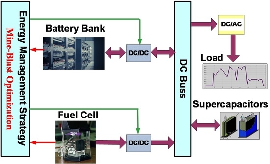
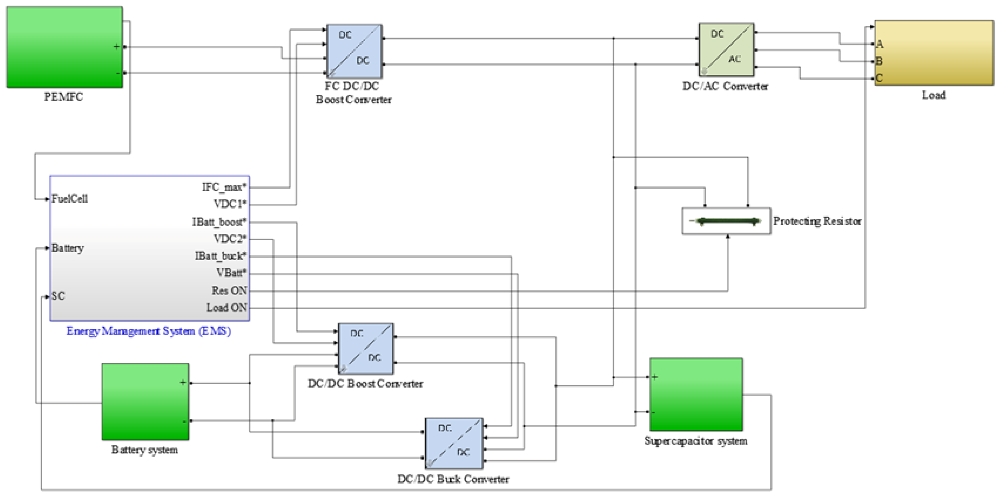
2. System Description
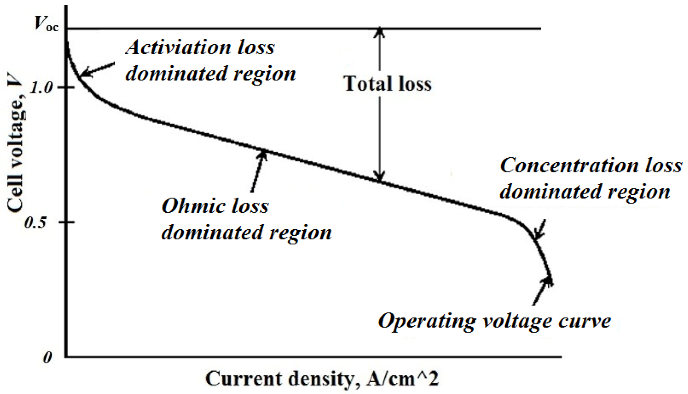
2.1. Fuel Cell

Despite the advantages of using the FC, some disadvantages exist. The slow response related to the load variation, unstable output voltage, a short lifetime because of the increasing in current ripple, and relatively high cost are some for the drawbacks of using FC [20]. In the modeling of FC, there are losses that have to be considered such as the activation, the ohmic, and the concentration losses. More details of modeling and simulation of the FC can be found in [21]. In the following, the relations that represent the reactions at the anode and the cathode of the FC are presented.
H 2 2 H + + 2 e       ( atanode )
2   H + + 2   e + + 1 2 O 2     H 2 O ( at   cathode )
H 2 + 1 2 O 2 H 2 O + e l e c t r i c a l e n e r g y + h e a t       ( Overall )
The output voltage of fuel can be formulated based by the following:
V F C = E N e r n e s t V a c t V o h m V c o n
where Vact is the activation voltage loss, Vohm is the ohmic voltage loss, and Vcon is the concentration voltage loss
E N e r n e s t = 1.229 0.85 × 10 3 ( T 298.15 ) + 4.3085 × 10 5 T ln ( P H 2 P O 2 )
where T denotes the cell temperature and PH2 and PO2 denote the partial pressures of the hydrogen and oxygen, respectively given by the following equations:
P H 2 = 0.5 R H a P s a t H 2 O ( 1 R H a P s a t H 2 O P a exp ( 1.635 ( I / A ) T 1.334 ) 1 )
P O 2 = R H c P s a t H 2 O ( 1 R H c P s a t H 2 O P c exp ( 4.192 ( I / A ) T 1.334 ) 1 )
where RHa and RHc are the anode and cathode vapor relative humilities, respectively; Pa and Pc are the pressures of anode and cathode inlets, respectively; A is the area of electrode; I is the FC current; and PsatH2O is the saturation pressure of water vapor in atm which is given by:
log 10 ( P s a t H 2 O ) = 2.95 × 10 2 ( T 273.15 ) 9.19 × 10 5 ( T 273.15 ) 2 + 1.44 × 10 7 ( T 273.15 ) 3 2.18
The following relation can be used to represent the activation voltage loss [4]:
V a c t = [ ξ 1 + ξ 2 T + ξ 3 T ln ( C O 2 ) + ξ 4 T ln ( I ) ]
where ξ1, ξ2, ξ3, and ξ4 are the FC model parametric coefficients and CO2 denotes oxygen concentration,
C O 2 = P O 2 5.08 × 10 6 exp ( 498 T )
The ohmic voltage loss can be estimated by the following equation:
V o h m = I ( R M + R C )
where RC is the contact to electron conduction equivalent resistance and RM denotes the membrane to proton resistance,
R M = ρ M l A
ρ M = 181.6 [ 1 + 0.03 ( i A ) + 0.062 ( T 303 ) ( i A ) 2.5 ] [ λ 0.634 3 ( i A ) ] exp [ 4.18 ( T 303 T ) ]
where ρM is the membrane specific resistivity, l is the thickness of membrane, and λ is the water content of the membrane.
The concentration voltage drop is represented by the following relation:
V c o n = b ln ( 1 I A I max )
where b denotes the concentration loss constant and Imax is the maximum current destiny.
The FC contains a number (n) of cells that are connected in series to increase the output voltage which can be estimated by the following equation:
V s t a c k = n V F C = n ( E N e r n e s t V a c t V o h m V c o n )
Figure 1 illustrates the output voltage at different current density of the cell.

2.2. Battery Model

The battery, as an energy storage device, can be used in a stand-alone power system as similar as the one that is found in transportation vehicles. Furthermore, it could also be used as an active component in the hybrid electrical power system by cooperating with the FC and the supercapacitor to produce a better overall performance of the power system. The Li-ion type was chosen because of its high capability to produce a high-energy density compared to the other lead-acids, NiMH and NiCd cells [22]. This makes Li-ion batteries the best choice for hybrid sources vehicles’ applications. To effectively take the BS SOC on the BS performance into consideration, voltage polarization was assumed to the BS discharging voltage formula. Also, to guarantee the simulation stability and to take the polarization resistance into consideration, a filtered BS was used current rather than the real BS current. The battery’s voltage of the Li-ion type is represented by Equation (16) as [23]:
V b a t t = E 0 K Q Q i t i t R b i + A b e ( B . i t ) K Q Q i t i *
where E0 is the BS constant voltage (V), Q is the BS capacity (Ah), K is the polarization constant V/(Ah), it is the actual BS charge (Ah), i* is the filtered battery current (A), Ab is the exponential zone amplitude (V), Rb is the battery internal resistance (Ω), and B is the exponential zone time constant inverse (Ah)−1.
In Equation (16), the polarization voltage is represented by “ K Q Q i t i t ” and the term “ K Q Q i t ” is denoting the polarization resistance (Polres).
In the charging phase, the BS potential difference is suddenly increased after it is fully charged and, in this case, the polarization resistance is updated as in Equation (17):
P o l r e s = K Q i t 0.1 Q

2.3. Supercapacitor (SC) Model

The supercapacitor is used with the battery to decrease the peak current in the battery when the load is very highly fluctuated. It has a high-efficiency cycle (about 100%) and is more suitable for both frequent charge/discharge cycles and storage energy compared to the battery, which is used to supply only the average of the needed power. SC characteristics are the same as the traditional capacitors, but it has the advantage of storing or releasing more energy because of its high capacitance. The SC’s cell is composed of double porous-type of carbon dipped in an electrolyte [24,25]. The SC’s cell capacitance can be formulated as in the following equations:
C = [ 1 C H + 1 C G C ] 1
with,
C H = N e 0 A i d
C G C = F Q c 2 N e R T sinh ( Q c N e 2 A i 8 R T 0 c )
where CH is the Helmholtz capacitance (F), CGC is the Gouy-Chapman capacitance (F), Ne is the number of layers in the electrode, is the permittivity of the electrolyte material (F/m), and 0 is the permittivity of free space (F/m). Ai is the inter-facial area between electrodes and electrolyte (m2), d is the length of Helmholtz layer (m), Qc is the electric charge of the cell (C), and c is the molar concentration (mol m−3).
Considering the series and parallel cells of the supercapacitor, the total capacitance can be estimated by Equation (21):
C T = N p N s C
Equation (22) calculates the supercapacitor output voltage with taking the resistive loss into consideration:
V S C = Q T C T R S C i S C
with,
Q T = N p Q c = i S C d t
where QT is the total charge (C), RSC is the SC module resistance (Ω), and iSC is the SC module current (A).

3. Energy Management Strategies

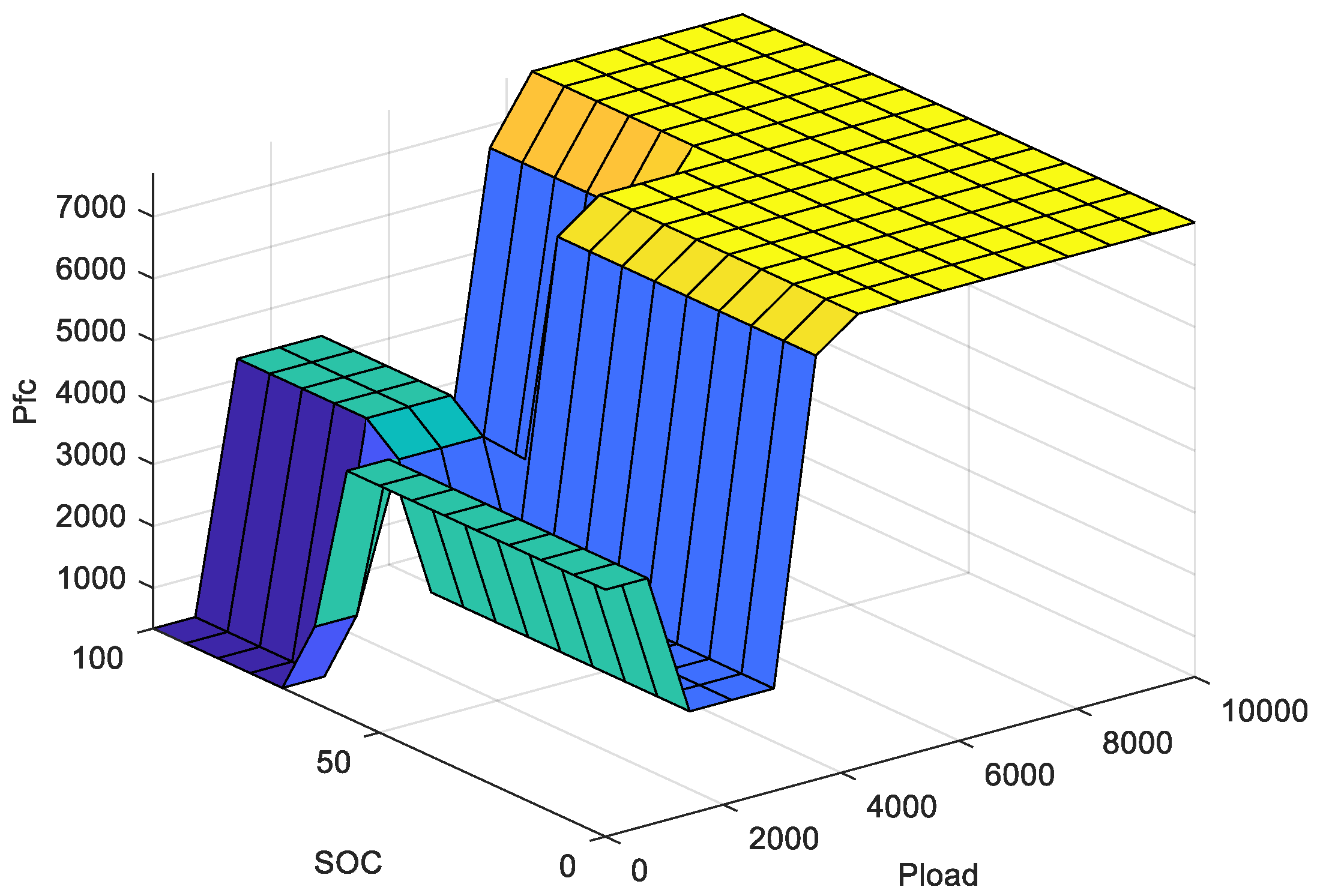
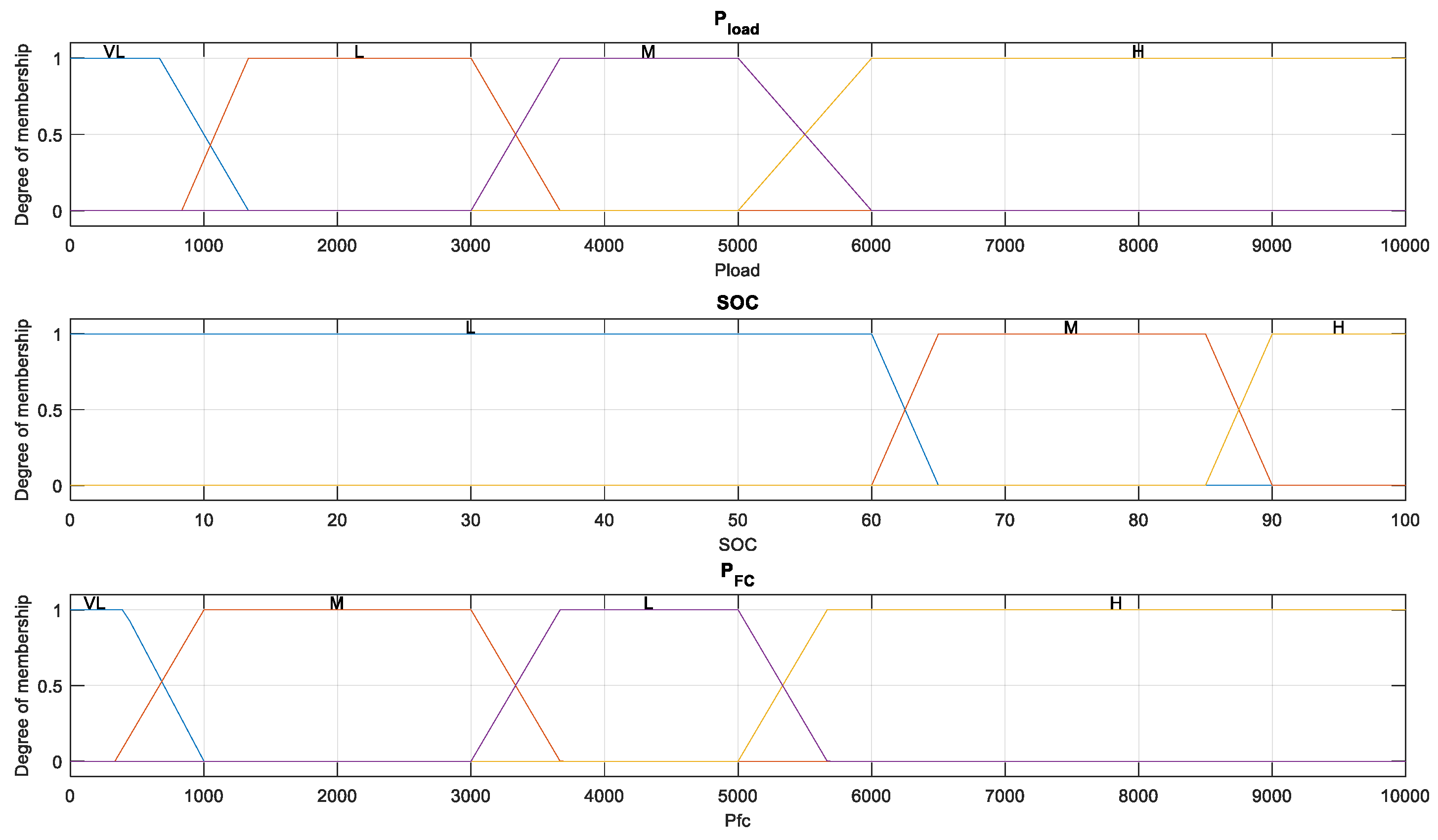
3.1. Fuzzy Logic Control (FLC)-Based EMS

Since several decades ago, FL has proved as an efficient tool in modeling and controlling many applications. FL usually includes three main sequential steps, beginning with the fuzzification step and ending with the defuzzification step. However, between both steps, there is the core of the fuzzy logic, which is the inference system [26]. This system always contains the fuzzy rules that are responsible for relating the system’s output to the system’s inputs. In the first step, the input variables have to be fuzzified by converting them from the crisp form to fuzzy form. This is usually done through a mapping process with the help of membership functions (MFs). The triangular and Gaussian are the two popular shapes of the MF. The defuzzification step is the inverse process to the fuzzification step. Two famous fuzzification methods are usually used: The center of gravity (COG) and the weighted average (Wavg). The “IF antecedent THEN consequence” is the structure of the fuzzy rule. The antecedent and the consequence represent the inputs’ logical combination and the output, respectively. Mamdani [27] and Takagi-Sugino-Kang (TSK) [28] are two well-known types of the fuzzy rule. In Mamdani-type, the consequence is in the fuzzy variable form. However, it takes the form of an input-output function in the TSK type. The rule’s shape of the fuzzy system can take the one of the following forms as shown below:
  • IF x1 is A1, …., and xn is An THEN y is B (Mamdani-type) (1)
  • IF x1 is A1, …., and xn is An THEN y = f(x1, …, xn) (TSK-type) (2)
where A1, …., An and B are the fuzzy MFs of the input variables and the output, respectively, while y = f(x1, …, xn) is either a linear or nonlinear crisp function of the input variables x1, …., and xn.
Eventually, for all fired rule’s output, these outputs are aggregated together to obtain the overall system’s output.
In this work, the load’s power and the BS SOC were taken as the inputs of the FLC, while its output was the FC’s power. Figure 2 illustrates the 3D surface of the MFs of the FLC of the FC system.
The MFs of the input variables, the load power, the SOC, and the FC power are illustrated in Figure 3. They are characterized by numbers of trapezoidal MFs of 5, 3, and 5, respectively. The fuzzy rules of Mamdani-type, used in this work, are constructed as listed in Table 1. The inference “max-min” and the defuzzification “COG” methods are utilized. The FC output current IFC can then be estimated in terms of the PFC resulted from the FLC and the FC voltage VFC.

3.2. Equivalent Consumption Minimization Strategy (ECMS)

This method aims to minimize the H2 consumption of the FC. In this study, a variable equivalence factor that depends on the battery SOC was employed. Additionally, to make this method less sensible to the SOC balancing coefficient (μ), the equivalence factor was added as a term in the objective function that needed to be optimized. Figure 4 shows the schematic of the ECMS. The optimization problem can be represented by the following equations:
M i n i m i z e F = ( P f c + α p P b a t t ) × Δ T
The constraints are:
P l o a d = P f c + P b a t t α p = 1 2 μ ( S O C 0.5 ( S O C max + S O C min ) ) S O C max + S O C min
The boundary conditions are described as follows:
P f c min P f c P f c max P b a t t min P b a t t P b a t t max 0 α p 2
where Pfc, Pbatt, and Pload denote the FC power, the battery power, and the load demand, respectively. αp denotes the penalty coefficient. ΔT denotes the sampling time. P f c min and P f c max denote the min and max FC’s power. P b a t t min and P b a t t max denote the min and max BS power. S O C min and S O C max denote the min and max SOC of BS. μ denote the SOC balancing coefficient.
In ECMS, the BS converters are controlled by the DC bus voltage. Accordingly, in the optimization procedure, the SC’s power was omitted. In case of the discharging of the SC, it was recharged again via the battery. In this case, in each load cycle, the total load energy was only produced by the FC and the battery.

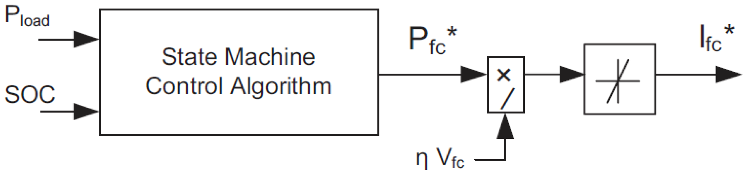
3.3. State Machine Control Strategy (SMCS)

Figure 5 illustrates the schematic diagram of the SMCS. More details about the states/decisions of SMCS can be found in [29]. From the figure, the FC power can clearly be estimated from the battery’s SOC and the load’s demand. Also, the output of the SMCS algorithm was the FC’s reference power. Therefore, to obtain the FC’s reference current, the response of the SMCS was then divided by both the FC voltage and the boost converter efficiency. The main disadvantage of this algorithm is the difficulty of switching between the different conditions. To overcome this problem, a hysteresis control is required. Consequently, this issue has an effect on the response of the EMS when the demand in the load changes.

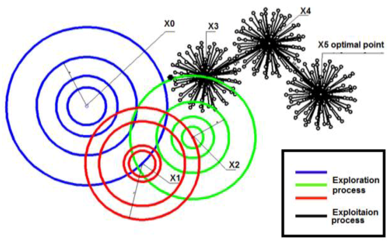
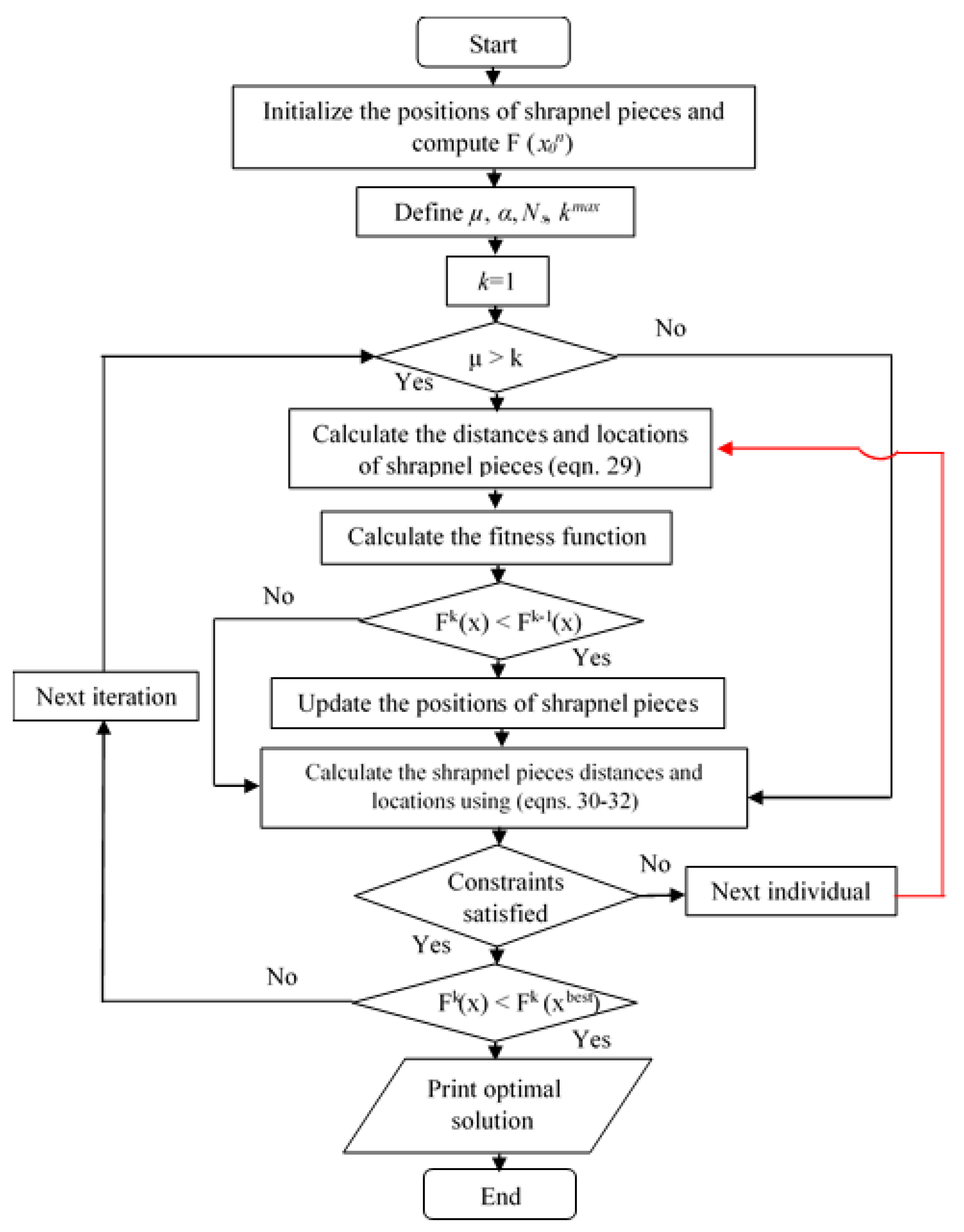
3.4. Mine Blast Algorithm (MBA)

Sadollah et al. introduced an optimizer inspired from observing the explosion of mine bomb, known as the mine blast algorithm (MBA) [30]. More details about the MBA optimizer can be found in [30]. In case of exploding the mine bomb, pieces of shrapnel are scattered and combined with other mine bombs near the scene of the blast that causes exploration of other bombs. In the MBA, the main objective of this algorithm is to obtain the most explosive mine bomb that produces the maximum number of damages. Shot-point is the initial mine bomb in this algorithm, and it is represented by x0n, where n is the shot-points number. This point generates shrapnel pieces that representing the individuals of number Ns and saved in a population. The shrapnel pieces explore new position of the mine bomb as given by the following equation:
x ( t + 1 ) n = x e ( t + 1 ) n + x t n e ( m ( t + 1 ) n d ( t + 1 ) n ) t = 0 , 1 , 2 , .
where x(t+1)n denotes the exploding bomb position, xtn denotes shot point position, and m(t+1)n and d(t+1)n denote the direction and distance of shrapnel pieces. The new exploited location is estimated by the following equation:
x e ( t + 1 ) n = d t n × r a n d × cos ( 360 N s )
To explore a new position, an exploration coefficient μ was used to control the switch between the exploration and the exploitation processes. The optimizer was performing the optimization process as long as the value of μ was greater than the iteration number k. In the current study, μ was set to 20. The new position of mine bomb is calculated as follows:
x e ( t + 1 ) n = d t n × | r a n d n | 2 × cos ( 360 N s ) t = 0 , 1 , 2 ,
On the other hand, the optimizer was switched to the exploitation process when μ was less than k. Therefore, in this case, the initial distance was gradually decreased so as to guarantee a converging optimization process. A user defined parameter α must also be set to obtain a convergent optimized solution. The distance is governed using the following equation:
d t n = d t 1 n e ( k α )
In exploitation process, the direction and distance of the shrapnel pieces are calculated as follows:
d t + 1 n = ( x t + 1 n x t n ) 2 + ( F t + 1 n F t n ) 2
m t + 1 n = F t + 1 n F t n x t + 1 n x t n
where Ft+1n is the fitness function at location t + 1. The exploration and exploitation processes are shown in Figure 6. The steps of MBA are explained in the flowchart illustrated in Figure 7. In the current study, the controlling parameters of the MBA optimizer were selected as follows: The number of shrapnel pieces was set to 50 and the number of iterations was set to 100.
The hydrogen consumption was minimized through the MBA optimizer based on ECMS, which is explained in Section 3.2.
The main strength of the proposed work is applying a recent and efficient metaheuristic optimization algorithm of the MBA as an energy management tool of hybrid FC, battery, and SC system. This system was used as an emergency power source to supply aircrafts in different landing situations. The application of the MBA will significantly contribute in minimizing the amount of the consumed hydrogen gas of the hybrid system more than that of the other conventional management strategies. However, in the future, many other recent heuristic approaches will be applied, and a comparative study will be held to identify the best one in such hybrid energy management system.

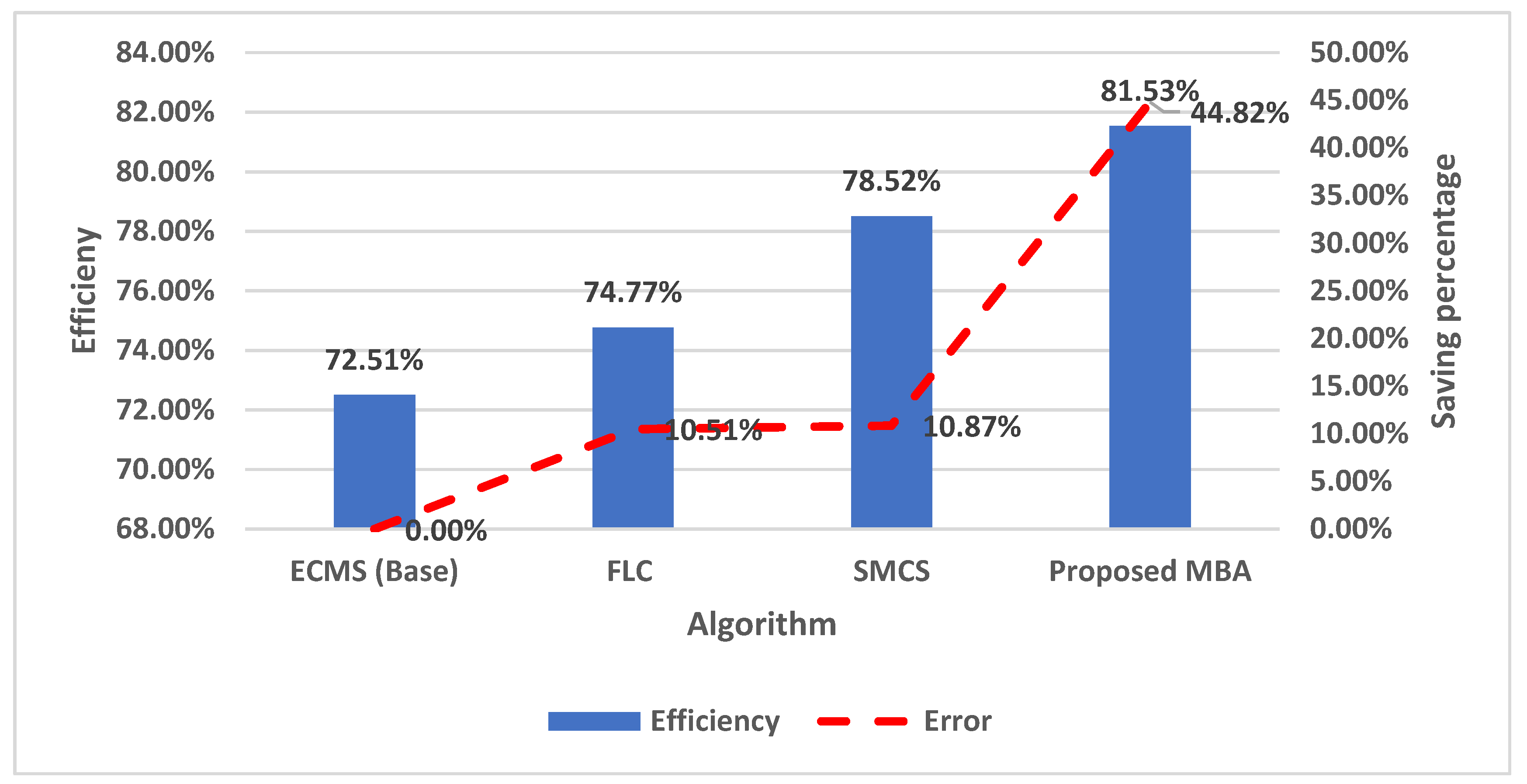
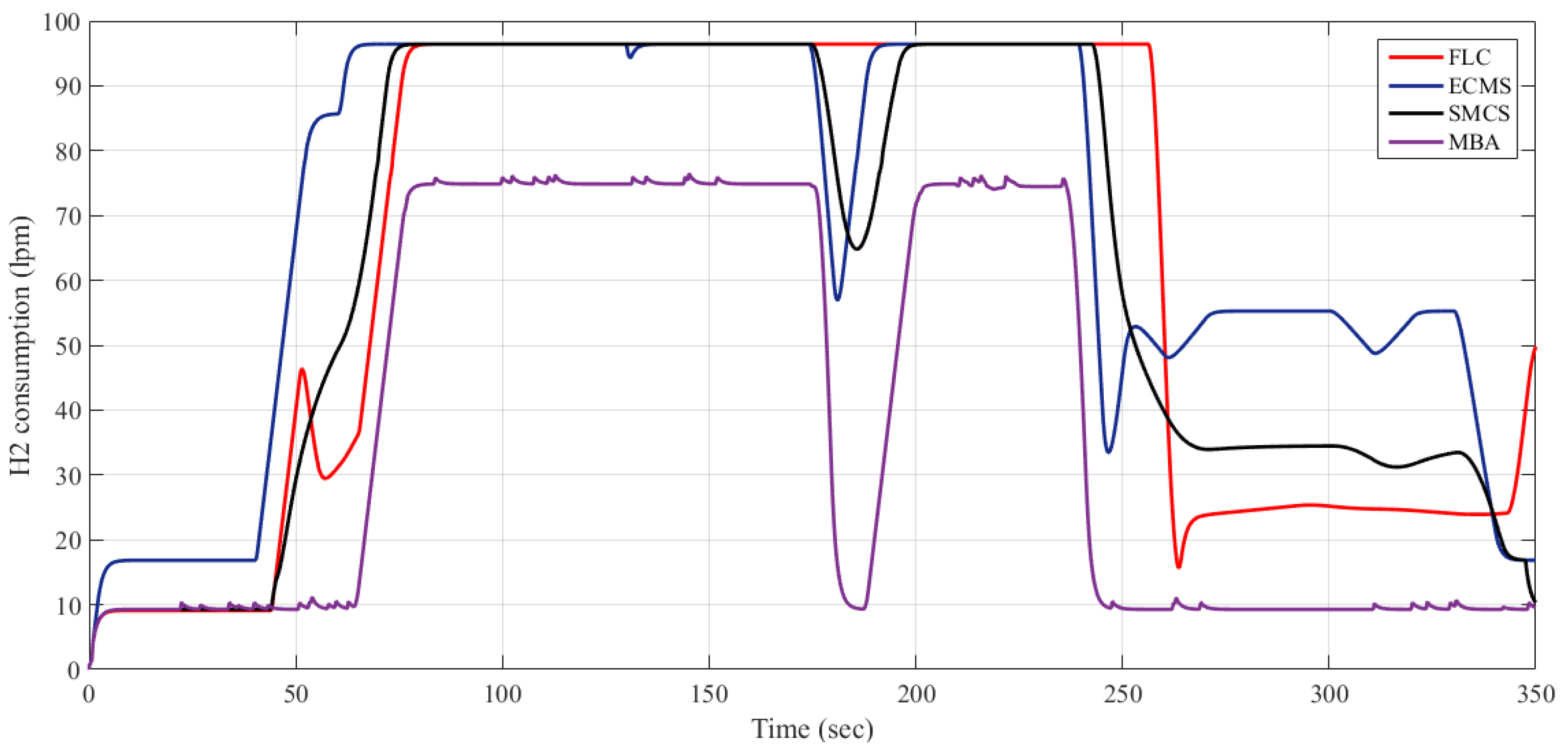
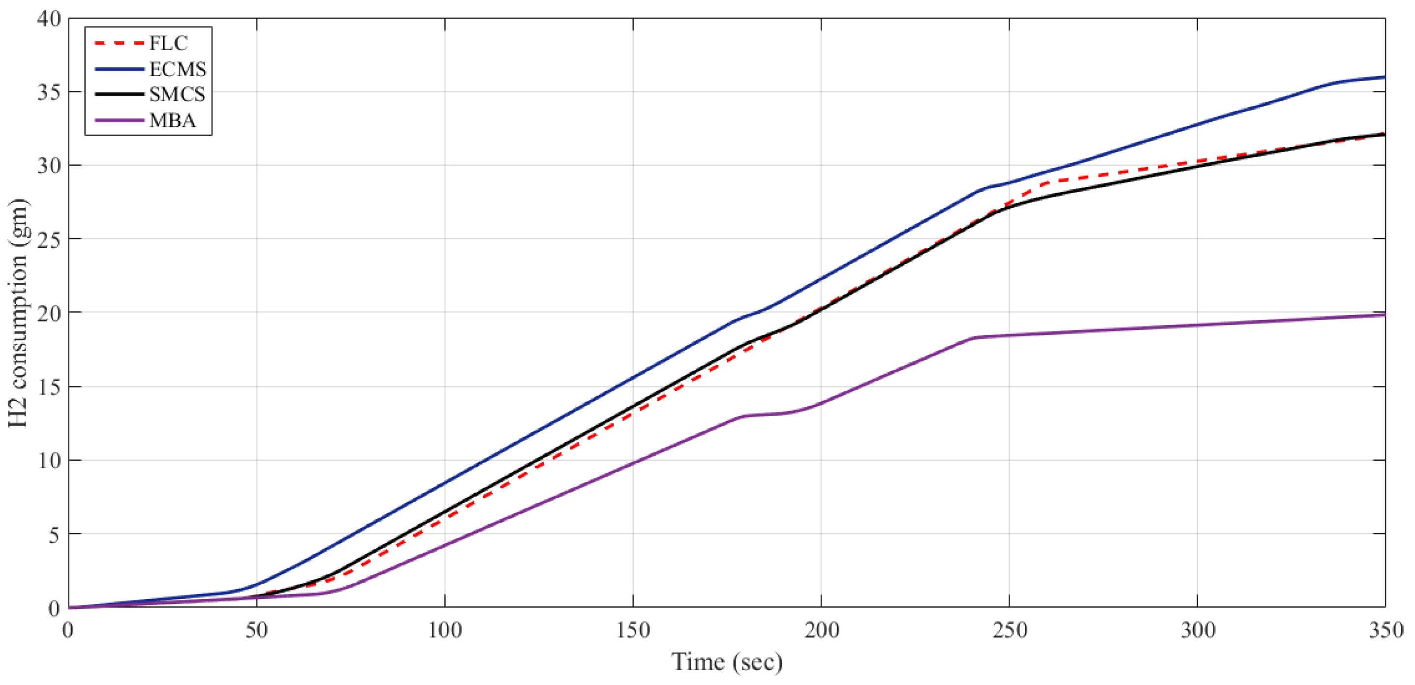
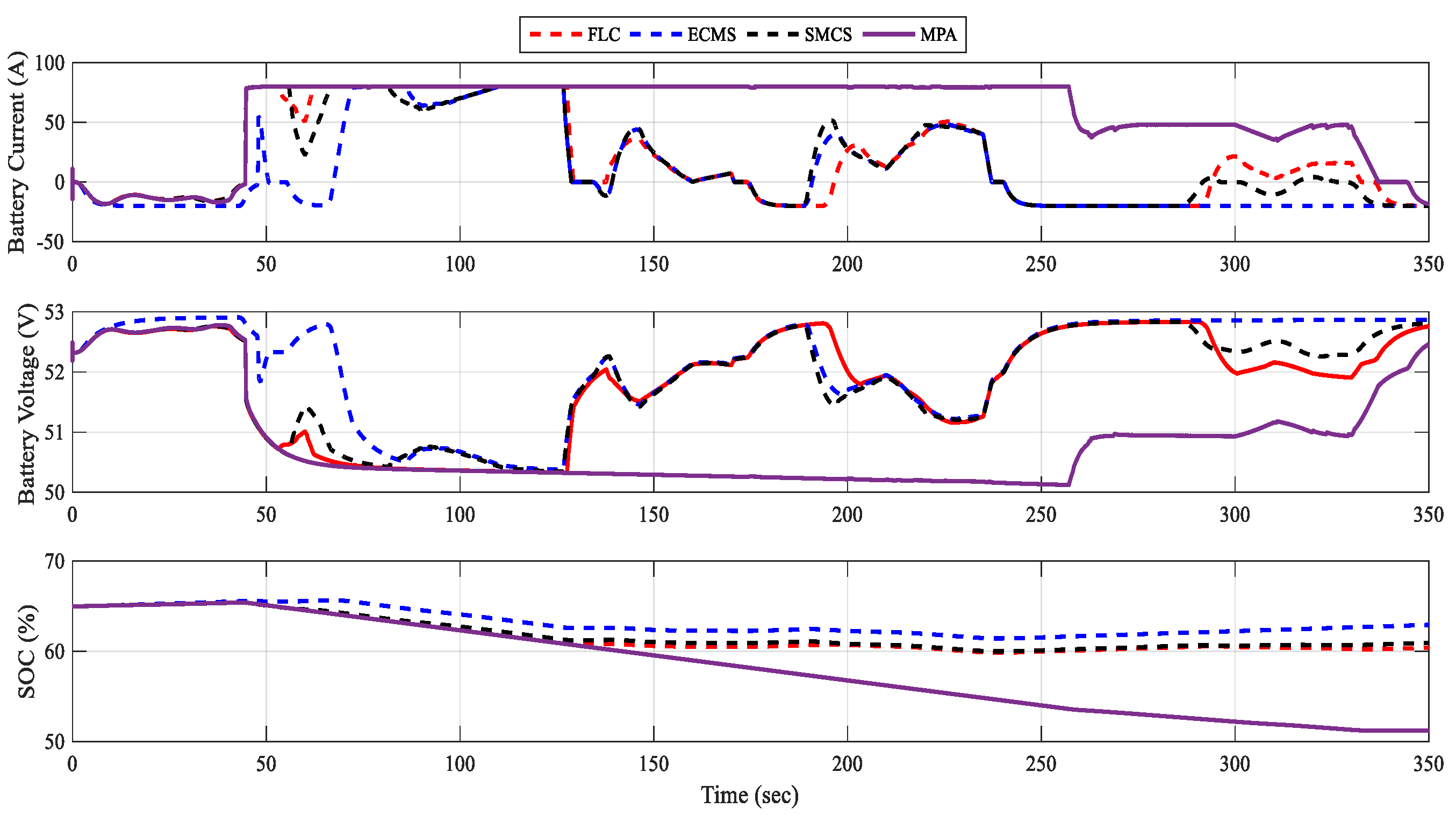
4. Results and Discussion

The comparison between the performances of the studied EMSs was carried out using Matlab© simulations. Figure 8 illustrates the Simulink model of the proposed FC/BS/SC hybrid system. It consisted of the following: A 12.5 kW, 30–60 V PEMFC type; a 48 V, 40 Ah battery storage; six series-connected SC, each with a rating of 15.6 F and 291.6 V; and a 12.5 kW FC DC/DC boost converter. Two DC/DC converters were used to control the battery storage. The first converter had 4 kW boost type to discharge the battery and the second had a 1.2 kW buck type to charge it. A 15 kVA, 200 V AC, 400 Hz inverter was employed to feed the AC load demand. For fair assessment of the simulations, the initial conditions for the BS and SC system were set to the same values. The two key factors for comparing the performance were the H2 consumption and the system efficiency. The efficiency was calculated via dividing the average load demand power by the average power generated from the fuel cell/battery/supercapacitor system. The comparative study of the H2 consumption and the overall efficiency was obtained using the proposed MBA-based EMS strategy and the other studied strategies given in Figure 9. The H2 consumption in Figure 9 was computed as a tolerance w.r.t., the approach that gives the largest H2 consumption which, in this case, is the ECMS. From the obtained results, one can see that in terms of the H2 fuel economy and the efficiency, the best EMS strategy among all studied strategies is the MBA-based optimizer. Applying the MBA optimizer decreased the H2 consumption to 19.85 gm, which is around a 10.5% decrease compared to both FLC and SMCS, and a decrease of 44.8% compared to the ECMS strategy. Furthermore, the efficiency was increased by 8.8%, 3.6%, and 12.19% compared to FLC, SMCS, and ECMS, respectively. Similar work has previously been done by Njoya et al. in [29], where the values of the overall efficiency using PI control and ECMS were 80.28% and 80.47%, respectively. This proved that the efficiency obtained through the current proposed MBA optimizer was better than that obtained in [29], despite a slight difference. Therefore, the proposed MBA-based management strategy was found to be superior among the compared strategies of SMCS, FLC, and ECMS in both hydrogen fuel economy and overall efficiency.
Figure 10 and Figure 11 show the time responses of the hydrogen consumptions obtained by each management strategy.
Figure 12, Figure 13 and Figure 14 can help to explain and understand the modes of operation as follows: At t = 0, the load demand was zero, so the FC started to charge the BS. At t = 40 s, the hybrid FC/BS/SC system started to supply the power to the load, and the excess load demand was fed using SC since it has a fast response to the sudden power demand. At the same time, the FC power increased gradually. At t = 45 s, the SC voltage level decreased under the reference voltage level (270 V). Accordingly, the BS was used for regulating the SC voltage in order to reach to the reference value again. At t = 48.5 s, the SC voltage equaled the reference voltage, so the BS gradually decreased its power to zero. Hence, the FC supplied the total load demand and recharges the SC simultaneously. At t = 60 s, the SC fed the excess transient load demand, whereas the FC power increased gradually. At t = 61.5 s, the BS regulated the DC bus voltage to the reference level and supported the FC in order to supply the excess load demand. At t = 70 s, the FC output power reached its maximum and the load’s extra demand was fed by the BS. At t = 110 s, the BS also reached its maximum and, in this case, the SC handled the load’s extra power. At t = 125 s, the load power decreased to a value lower than the FC maximum power. Because the FC response is usually slow during transients, the extra FC energy was then shifted for charging the SC. At t = 126 s, the DC bus voltage reached 270 V. However, the BS discharged and dropped to zero. At t = 170 s, the load demand decreased to a value lower than the FC maximum power. Therefore, the extra FC power was then used to charge both the BS and SC. At t = 180 s, the load increased abruptly, so the SC responded quickly to this fast change and handled the extra load demand. At t = 185 s, to regulate the DC bus voltage, the BS discharged to help the FC in supplying the power to the extra load demand. At t = 235 s, the load power was suddenly decreased. Accordingly, the exceeded FC energy was then used to charge the BS and SC. At t = 250 s, the FC approximately supplied the total load power. At t = 330 s, the load demand was reduced to zero. Therefore, the FC gradually decreased its power to its optimal power and also recharged the BS.

5. Conclusions

An effective energy management strategy based on mine-blast optimization algorithm (MBA) for optimally sharing the demanded load-power among different generating sources in a hybrid system was proposed. This system was composed of FCs, battery storage, and SCs, and was used to supply a highly fluctuated load profile. In terms of the hydrogen consumption economy and overall efficiency, the proposed strategy was compared with three previously used and popular strategies: FLC, SMCS, and ECMS. The obtained results proved that the MBA-based strategy is the best compared to the others. It efficiently decreased the hydrogen consumption by about 10.5% compared to the FLC and SMCS strategies, while it decreased hydrogen consumption by 44.8% compared to the ECMS strategy. Furthermore, the efficiency was increased by 8.8%, 3.6%, and 12.19% compared to the FLC, SMCS, and ECMS strategies, respectively. In conclusion, the proposed strategy has an outstanding performance relative to the other strategies.

Author Contributions

Conceptualization, A.M.N., A.F. and H.R.; methodology, A.M.N., A.F. and H.R.; software, A.M.N., A.F. and H.R.; validation, A.F. and H.R.; formal analysis, A.F. and H.R.; investigation, A.M.N., and H.R.; resources, A.M.N., A.F. and H.R.; writing—original draft preparation, A.M.N., A.F. and H.R.; writing—review and editing, A.M.N, A.F. and H.R.

Funding

This research was funded by Deanship of Scientific Research at Prince Sattam Bin Abdulaziz University grant number 2019/01/10508 and the APC was funded by Deanship of Scientific Research at Prince Sattam Bin Abdulaziz University grant number.

Acknowledgments

This project was supported by the Deanship of Scientific Research at Prince Sattam Bin Abdulaziz University under the research project No. 2019/01/10508.

Conflicts of Interest

The authors confirm no conflict of interest.

References

  1. Central Intelligence Agency. The World Factbook; Central Intelligence Agency: Washington, DC, USA, 2017.
  2. Fathy, A.; Rezk, H. Multi-verse optimizer for identifying the optimal parameters of PEMFC model. Energy 2018, 143, 634–644. [Google Scholar] [CrossRef]
  3. Rezk, H.; Dousoky, G.M. Technical and economic analysis of different configurations of stand-alone hybrid renewable power systems—A case study. Renew. Sustain. Energy Rev. 2016, 62, 941–953. [Google Scholar] [CrossRef]
  4. Sakhare, A.; Davari, A.; Feliachi, A. Fuzzy logic control of fuel cell for stand-alone and grid connection. J. Power Sources 2004, 135, 165–176. [Google Scholar] [CrossRef]
  5. Tekin, M.; Hissel, D.; Pera, M.C.; Kauffmann, J.M. Energy management strategy for embedded fuel cell system using fuzzy logic. In Proceedings of the 2004 IEEE International Symposium on Industrial Electronics, Ajaccio, France, 4–7 May 2004; Volume 1, pp. 501–506. [Google Scholar]
  6. Tekin, M.; Hissel, D.; Pera, M.C.; Kauffmann, J.M. Energy-Management Strategy for Embedded Fuel-Cell Systems Using Fuzzy Logic. IEEE Trans. Ind. Electron. 2007, 54, 595–603. [Google Scholar] [CrossRef]
  7. Jeong, K.-S.; Lee, W.-Y.; Kim, C.-S. Energy management strategies of a fuel cell/battery hybrid system using fuzzy logics. J. Power Sources 2005, 145, 319–326. [Google Scholar] [CrossRef]
  8. Gao, D.; Jin, Z.; Lu, Q. Energy management strategy based on fuzzy logic for a fuel cell hybrid bus. J. Power Sources 2008, 185, 311–317. [Google Scholar] [CrossRef]
  9. Kisacikoglu, M.C.; Uzunoglu, M.; Alam, M.S. Load sharing using fuzzy logic control in a fuel cell/ultracapacitor hybrid vehicle. Int. J. Hydrogen Energy 2009, 34, 1497–1507. [Google Scholar] [CrossRef]
  10. Han, J.; Park, Y.; Kum, D. Optimal adaptation of equivalent factor of equivalent consumption minimization strategy for fuel cell hybrid electric vehicles under active state inequality constraints. J. Power Sources 2014, 267, 491–502. [Google Scholar] [CrossRef]
  11. Zhang, W.; Li, J.; Xu, L.; Ouyang, M. Optimization for a fuel cell/battery/capacity tram with equivalent consumption minimization strategy. Energy Convers. Manag. 2017, 134, 59–69. [Google Scholar] [CrossRef]
  12. Torreglosa, J.P.; Jurado, F.; Garcıa, P.; Fernandez, L.M. Hybrid fuel cell and battery tramway control based on an equivalent consumption minimization strategy. Control Eng. Pract. 2011, 19, 1182–1194. [Google Scholar] [CrossRef]
  13. Fleuren, M.; Romijn, T.; Donkers, M. An equivalent consumption minimisation strategy based on 1-step look-ahead stochastic dynamic programming. In Proceedings of the 4th IFAC Workshop on Engine and Powertrain Control, Simulation and Modeling (E-COSM 2015), Columbus, OH, USA, 23–26 August 2015; pp. 72–77. [Google Scholar]
  14. Zhang, G.; Chen, W.; Yu, J.; Li, Q. Study on equivalent consumption minimization strategy for fuel cell hybrid tramway. In Proceedings of the IEEE Transportation and Electrification Conference and Expo, Asia-Pacific, Harbin, China, 7–10 August 2017. [Google Scholar]
  15. Hofman, T.; Steinbuch, M.; van Druten, R.; Serrarens, A. Rule-based equivalent fuel consumption minimization strategies for hybrid vehicles. In Proceedings of the 17th World Congress International Federation of Automatic Control, Seoul, Korea, 6–11 July 2008; pp. 5652–5657. [Google Scholar]
  16. Zheng, C.; Oh, C.; Park, Y.; Cha, S. Fuel economy evaluation of fuel cell hybrid vehicles based on equivalent fuel consumption. Int. J. Hydrogen Energy 2012, 37, 1790–1796. [Google Scholar] [CrossRef]
  17. Fernandez, L.M.; Garcia, P.; Garcia, C.A.; Jurado, F. Comparison of control schemes for a fuel cell hybrid tramway integrating two dc/dc converters. Int. J. Hydrogen Energy 2010, 3, 5731–5744. [Google Scholar] [CrossRef]
  18. Attaianese, C.; di Monaco, M.; Tomasso, G. Power Control for Fuel-Cell–Supercapacitor Traction Drive. IEEE Trans. Veh. Technol. 2012, 61, 1961–1971. [Google Scholar] [CrossRef]
  19. Li, Q.; Yang, H.; Han, Y.; Li, M.; Chen, W. A state machine strategy based on droop control for an energy management system of PEMFC-battery-supercapacitor hybrid tramway. Int. J. Hydrogen Energy 2016, 41, 16148–16159. [Google Scholar] [CrossRef]
  20. Lee, J.H.; Lalk, T.R.; Appleby, A.J. Modeling electrochemical performance in large scale proton exchange membrane fuel cell stacks. J. Power Sources 1998, 70, 258–268. [Google Scholar] [CrossRef]
  21. Ramos-Paja, C.A.; Giral, R.; Martinez-Salamero, L.; Romano, J.; Romero, A.; Spagnuolo, G. A PEM Fuel-Cell Model Featuring Oxygen-Excess-Ratio Estimation and Power-Electronics Interaction. IEEE Trans. Ind. Electron. 2010, 57, 1914–1924. [Google Scholar] [CrossRef]
  22. García, P.; Torreglosa, J.P.; Fernandez, L.M.; Jurado, F. Viability study of a FC-battery-SC tramway controlled by equivalent consumption minimization strategy. Int. J. Hydrogen Energy 2012, 37, 9368–9382. [Google Scholar] [CrossRef]
  23. Tremblay, O.; Dessaint, L.-A. Experimental Validation of a Battery Dynamic Model for EV Applications. World Electr. Veh. J. 2009, 3, 289–298. [Google Scholar] [CrossRef] [Green Version]
  24. Oldham, K. A Gouy–Chapman–Stern model of the double layer at a (metal)/(ionic liquid) interface. J. Electroanal. Chem. 2008, 613, 131–138. [Google Scholar] [CrossRef]
  25. Amokrane, S. Microscopic Description of the Electrode Surface and Double Layer Capacity at the Electrode/solution Interface. Electrochim. Acta 1996, 41, 2097–2105. [Google Scholar] [CrossRef]
  26. Nassef, A.M.; Sayed, E.T.; Rezk, H.; Abdelkareem, M.A.; Rodriguez, C.; Olabi, A.G. Fuzzy-modeling with Particle Swarm Optimization for enhancing the production of biodiesel from Microalga. Energy Sour. Part A Recovery Utiliz. Environ. Eff. 2019, 41, 2094–2103. [Google Scholar] [CrossRef]
  27. Mamdani, E.H.; Assilian, S. An Experiment in Linguistic Synthesis with a Fuzzy Logic Controller. Int. J. Man Mach. Stud. 1975, 7, 1–15. [Google Scholar] [CrossRef]
  28. Takagi, T.; Sugeno, M. Fuzzy identification of systems and its applications to modelling and control. IEEE Trans. Syst. 1985, 15, 116–132. [Google Scholar]
  29. Njoya, M.; Louis, A.D.; Kamal, A.H. A comparative study of energy management schemes for a fuel-cell hybrid emergency power system of more-electric aircraft. IEEE Trans. Ind. Electron. 2004, 61, 1320–1334. [Google Scholar] [CrossRef]
  30. Sadollah, A.; Bahreininejad, A.; Eskandar, H.; Hamdi, M. Mine blast algorithm: A new population based algorithm for solving constrained engineering optimization proble. Appl. Soft Comput. 2013, 13, 2592–2612. [Google Scholar] [CrossRef]
Figure 1. Fuel cell output voltage versus current density.
Energies 12 03796 g001
Figure 2. The 3D surface of the fuel cell (FC) system input-output membership functions (MFs).
Energies 12 03796 g002
Figure 3. The input-output membership functions of the fuel cell–fuzzy logic control (FC–FLC).
Energies 12 03796 g003
Figure 4. The block diagram of the equivalent fuel consumption minimization strategy (ECMS).
Energies 12 03796 g004
Figure 5. State machine control.
Energies 12 03796 g005
Figure 6. Mine blast algorithm (MBA) exploration and exploitation processes.
Energies 12 03796 g006
Figure 7. Flowchart of MBA.
Energies 12 03796 g007
Figure 8. Simulink model of fuel cell (FC)/supercapacitor (SC)/batteries (BS) hybrid system.
Energies 12 03796 g008
Figure 9. Overall efficiency and saving percentage of hydrogen consumption.
Energies 12 03796 g009
Figure 10. H2 consumption variation for different considered methods.
Energies 12 03796 g010
Figure 11. H2 consumption variation in gm for different considered methods.
Energies 12 03796 g011
Figure 12. Variation of load and generation powers with time.
Energies 12 03796 g012
Figure 13. Time responses of the battery’s state of charge (SOC), current, and voltage.
Energies 12 03796 g013
Figure 14. Time responses of the battery’s SOC, current, and voltage.
Energies 12 03796 g014
Table 1. FC system fuzzy rules.
SOC
HighMediumLow
PloadVery LowVery LowVery LowLow
LowLowLowMedium
MediumMediumMediumHigh
HighHighHighHigh

