Article

Experimental and Numerical Study on the Effect of Interfacial Heat Transfer on Performance of Thermoelectric Generators

Merchant Marine College, Shanghai Maritime University, Shanghai 201306, China
*
Author to whom correspondence should be addressed.
Energies 2019, 12(19), 3797; https://doi.org/10.3390/en12193797
Submission received: 26 July 2019 / Revised: 15 September 2019 / Accepted: 1 October 2019 / Published: 8 October 2019

Abstract

:
The application of thermoelectric generator (TEG) systems in waste heat recovery has attracted more and more attention. In this work, the effect of interfacial heat transfer on the performance of TEG module was experimentally and numerically investigated. Three kinds of thermal greases with thermal conductivities of 2.0, 2.5, and 3.0 W/(m∙K) were used as thermal interface materials (TIMs) to improve interfacial heat transfer at different external pressures ranging from 0.1 to 0.4 MPa. The open-circuit voltage, output power, and thermal interfacial resistance were measured at different experimental conditions. It was found that the performance of the TEG module can be greatly improved by using thermal greases as TIMs. The open-circuit voltages increased from 1.73 to either 3.07, 3.4, or 3.57 V with k = 2.0, 2.5, and 3.0 W/(m∙K) thermal greases respectively used as TIMs when the temperature difference was 60 °C and external pressure was 0.1 MPa. However, the performance of the TEG was slightly affected by external pressure when thermal greases used as TIMs. The open-circuit voltages were 3.07, 3.13, 3.17, and 3.20 V at external pressures of 0.1, 0.2, 0.3, and 0.4 MPa when the temperature difference ΔT = 60 °C and k = 2.0 W/(m∙K) thermal greases were used as TIMs.

1. Introduction

The energy consumption of automobiles has increased sharply with the rapid development of automobile industry in recent years. The automobiles were generally powered by internal combustion engines which have low energy conversion efficiency. Approximately 30%–45% of the fuel energy is discharged into the air with the exhaust gas [1]. In order to reduce the energy waste and environmental pollution, various heat recovery technologies were employed in the automobile industry, including metal hydride systems, zeolite systems, thermoacoustic systems, active magnetic regenerator systems, absorption systems, and thermoelectric devices [2]. The thermoelectric generation technology is a power generation technology based on the Seebeck effect, which can directly convert thermal energy into electrical energy [3]. The Seebeck effect is also known as the first thermoelectric effect, referring to a thermoelectric phenomenon in which a voltage difference is generated between two conductors or semiconductors substances under the influence of temperature difference. Compared with the other heat recovery techniques, the main merits of thermoelectric power generation technology include compactness, simple structure, no mechanical moving parts, and zero emission [4,5,6].
At present, the development of thermoelectric power generation devices was limited by high cost and low energy conversion rate. The researchers mainly focus on improving the thermoelectric conversion efficiency of thermoelectric materials [7,8,9,10,11,12] and optimizing the thermal management of thermoelectric generation devices [13,14,15,16,17,18]. In terms of improving the conversion rate of thermoelectric materials, by reducing the material dimensions, the existing thermoelectric materials can be made into nanotubes, which can greatly improve the ZT value of materials [7]. The thermoelectric conversion efficiency of the latest thermoelectric material can reach up to 17% and 20.9% at 500 and 700 °C respectively [8]. The effective temperature difference between the hot and cold sides of the TEG module was greatly affected by the heat transfer process when the heat source and heat sink were fixed. The temperature difference can be improved by applying proper heat transfer technologies and, thus, the efficiency of the TEG module can also be improved [17,18,19,20,21,22]. Zhao et al. proposed an intermediate fluid thermoelectric generator system. The waste exhaust heat was transferred through the phase change process of the intermediate fluid. The peak output power increased by 32.6% and the optimal thermoelectric module area was reduced by 73.8%. the generation capacity per unit area is 1162 W/m2 at peak output power, which is 5.12 times that of the traditional thermoelectric generator system [17]. Lu et al. investigated rectangular offset strip fins and metal foams to enhance heat transfer for an exhaust heat exchanger of a thermoelectric generator system. Results showed that there existed optimal fin transverse spacing and fin thickness for the maximum net power output. The total power output and efficiency of the TEG can be greatly improved by the metal foams [19]. Wang et al. introduced dimpled surfaces to replace the inserts fins in the conventional hot heat exchanger. Results showed that the pressure drop in the TEG with dimpled surface was reduced by 20.57%, and the net power output was increased by 173.60% [21]. Lesage et al. investigated thermoelectric power improvement due to heat transfer enhancement with the application of three different flow tribulating inserts. Results showed that inserts with protruding panels were shown to be the most effective [22].
In order to maintain a larger and more stable temperature difference of the thermoelectric generation chips, researchers have focused on optimizing the heat transfer process of the thermoelectric power generation device. By optimizing the structural design of the heat sink, the power generation efficiency of the thermoelectric generation device can be increased by 88.70% [23]. Wang et al. studied the influence of thermal contact resistance on the efficiency of the thermoelectric generation device. Results show that with the decrease of thermal contact resistance, the power generation and conversion efficiency were significantly improved [24]. Astrain et al. studied the influence of the thermal resistance between the cold and heat sources on the efficiency of the thermoelectric generation system by numerical simulation. Results show that the power generation efficiency can be increased by 10% when the thermal resistance is reduced by 8% [25]. Kim proposed the concept of direct contact hotspot generators, which reduced thermal contact resistance between generators and hot and cold source. The proposed system can achieve a maximum output power of 43 W and 2% conversion efficiency [26]. Lv et al. investigated advantages and disadvantages of three types of heat exchangers in a thermoelectric setup, which includes air, water cooling, and heat pipe heat exchangers [27]. Yin et al. introduced a phase change material in the thermoelectric power generation device. The introduction of the phase change material stabilizes the temperature of the hot and cold source of the thermoelectric power generation device and, therefore, the power generation efficiency of the thermoelectric power generation device was improved and the efficiency was improved by 23.52% [28]. Yu et al. used the numerical simulation method to study the working characteristics of the thermoelectric power generation device under conditions of high temperature difference [29].
Through the above literature review, it can be found that thermal contact resistance or interfacial heat transfer between contacting solids plays an importance role in the performance of TEG module. Thermal contact resistance was affected by many factors such as external pressure, thermal conductivity of TIMs, surface roughness, wettability, etc. External pressure and thermal conductivity of TIMs are the most easily adjusted parameters that affect the thermal contact resistance in practical applications. The aim of this paper is to quantitatively study the influence of external pressure and thermal conductivity of TIMs on the performance of thermoelectric generator. The experimental results in this paper will provide reference for the thermoelectric generator in practical application.

2. Experiment Setup and Numerical Modeling

2.1. Numerical Modeling of Thermoelectric Module

In a typical assembly of thermoelectric system, as shown in Figure 1, the hot side of the TEG module is attached to heat source, while the cold side is attached to heat sink. Thus, a one-dimensional heat conduction from heat source to heat sink was formed. The existence of the one-dimensional thermal field results in a temperature difference between the hot side and the cold side of TEG module, which converts thermal energy into electrical energy. The temperature of the TEG system was generally assumed to be continuous at the interfaces between the TEG module and heat source and heat sink. However, a temperature difference exists at the contact interfaces due to the thermal contact resistance. The temperature difference can be calculated by Equation (1) according to one-dimensional steady heat conduction.
R c = Δ T c / Q ,
where Rc is the thermal contact resistance (mm2K/W), ΔTc is the temperature difference across the contacting interfaces, and Q is the heat flux through the contacting interfaces (W/mm2).
The existence of thermal contact resistance will reduce the temperature difference between the hot and cold side of the TEG module, which eventually reduces the output power and efficiency of the TEG module. The open-circuit voltage U of a TEG can be calculated by Equation (2) based on the Seebeck effect.
U = α ( T H T C ) ,
where α is the Seebeck coefficient of the TEG module (V/K), and TH and TC are the temperatures of the hot and cold sides of the TEG module (K), respectively.
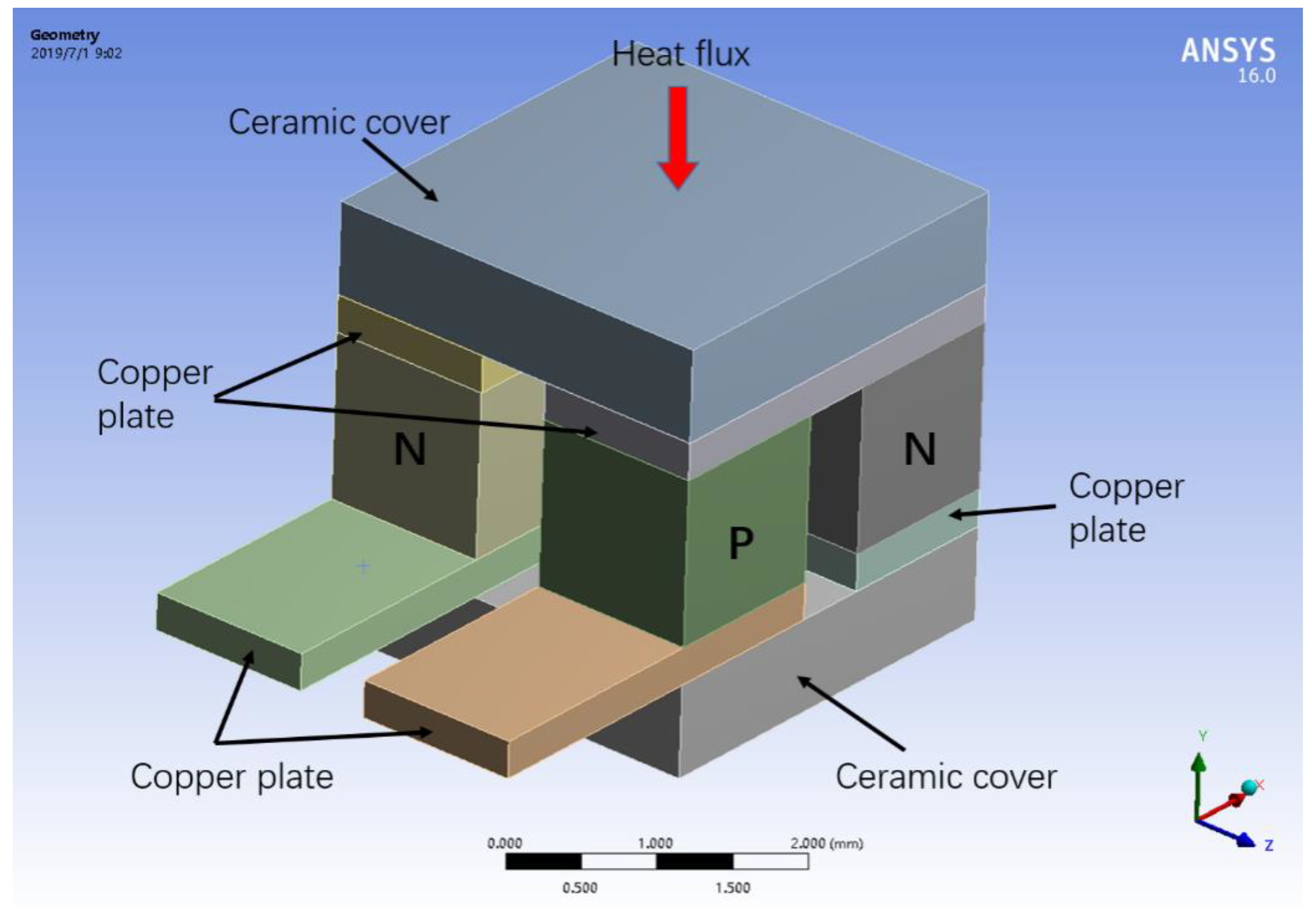
As shown in Figure 2, a numerical model was built to characterize the electrical and thermal performance of the TEG module. The ANSYS MultiphysicsTM thermoelectric system was employed to solve the electric charge and energy equations using the finite element method. The measured temperatures at the heating and cooling plate were used as the boundary conditions for the temperature field in the simulation [30]. It was composed of P/N(P type semiconductor/N type semiconductor) legs, copper plates, and ceramic covers. The P/N legs covert thermal energy to electrical energy, the copper plates connect the P/N legs in series, and the ceramic covers are used as electrical insulator. The thermal electrical module used in the experiment in this paper has 199 pairs of P/N legs. In order to save the computing time, the established numerical model only contains 2 pairs of P/N legs. Maintaining the cooling water at 20 °C by a chiller, the performance of thermoelectric module device is experimentally tested for various hot-side temperatures. In order to avoid the effect of temperature on the thermal and electrical properties of each component of TEG module and the damage of TEG module at high temperature, the hot-side temperature was set at 80, 85, 90, 95 °C. The physical properties of each component in the thermoelectric module are shown in Table 1.

2.2. Experimental System

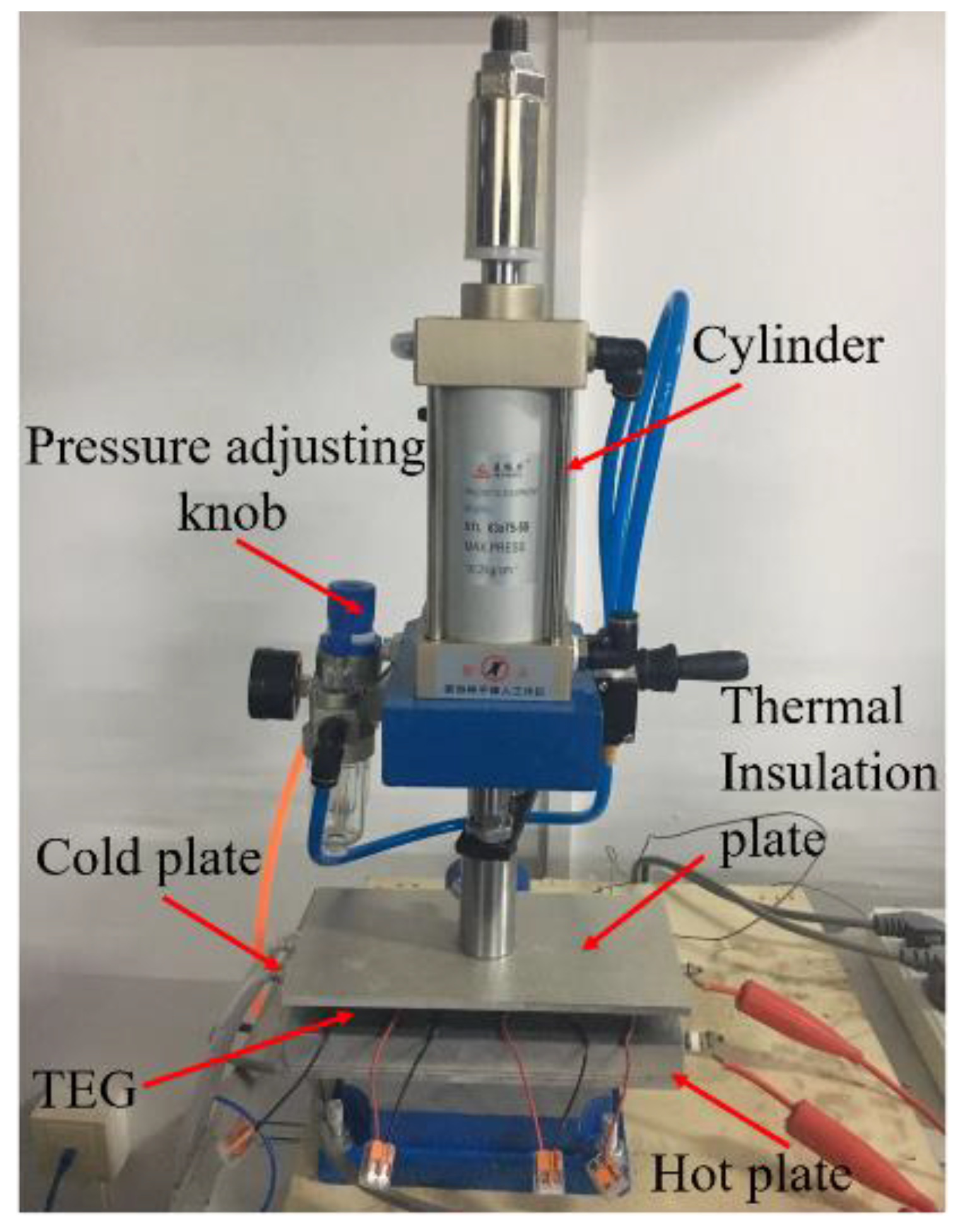
The experimental system is shown in Figure 3, and it mainly consists of hot and cold plates, a thermoelectric module, thermal insulation plates, and a pneumatic punch. The hot plate was used as the hot source of this experiment with a heating power of 1000 W and its size was 200 mm × 100 mm × 10 mm. The heating power of the hot plate can be adjusted by a voltage regulator, thereby changing the temperature of the hot plate. Three thermocouples were fixed on the hot plate to accurately measure the temperature. The cold plate is made of aluminum with water channels cased in it. The water bath was used to provide circulating water for the cold plate to main the temperature at 20 °C. Three thermocouples were fixed on the hot plate to accurately measure the temperature. A pneumatic punch was used to adjust external loading pressures for the thermoelectric module. Compressed air was connected to the cylinder and the pressure could be adjusted using a pressure-adjusting knob. A commercial bismuth telluride (Bi2Te3) thermoelectric module TEG1-199-1.4-0.5 (44 mm × 40 mm × 3 mm with 199 pairs of P/N junctions) was tested in this work. The specific parameters of the thermoelectric module are shown in Table 2.
The use of the thermal interface materials (TIMs) and the applied external load will significantly affect the interfacial heat transfer between two contacting surfaces. As shown in Figure 3, interfacial heat transfer occurs at the contacting interfaces between hot, cold plates, and TEG module. In order to study the influence of interface heat transfer on the efficiency of TEG module, different thermal interface materials and external pressures were employed during the experiment process. In this paper, three kinds of thermal greases with thermal conductivities of 2.0, 2.5, and 3.0 W/(m∙K) were used as the thermal interface material. The external loading pressure can be adjusted by the pressure of compressed air and, in this paper, the pressures of compressed air were set as 0.1, 0.2, 0.3, and 0.4 MPa. Thermal grease was firstly smeared on both sides of TEG module and the mating sides of cold and hot plates. Then, the pressure of compressed air was adjusted to the required value. When the thermal steady state condition was reached, the open-circuit voltage and output power of thermoelectric module were recorded.

3. Results and Discussion

3.1. The Effect of TIMs on Performance of the TEG Module

3.1.1. Effect of Thermal Greases on Open-Circuit Voltage

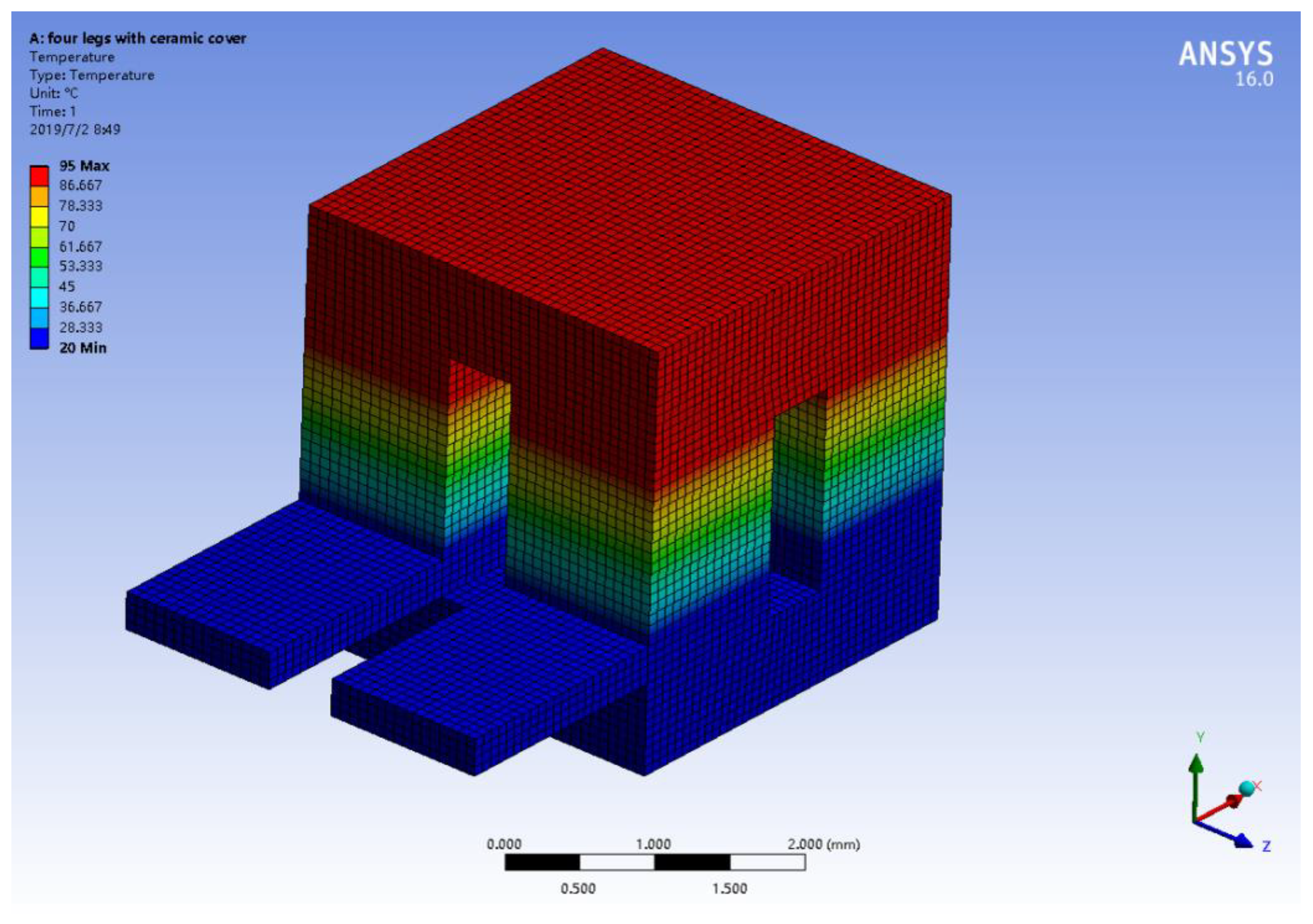
Maintaining the cooling water at 20 °C, the performance of thermoelectric module device was numerically analyzed for various hot-plate temperatures of 80, 85, 90, and 95 °C. Taking the temperature of hot plate at 95 °C as an example, the temperature distribution of the thermoelectric system is shown in Figure 4. The top side of the ceramic cover was set as 95 °C and the low side of ceramic cover was set as 20 °C When a steady state was reached, a uniform temperature distribution was formed. The heat conduction process was one-dimensional.
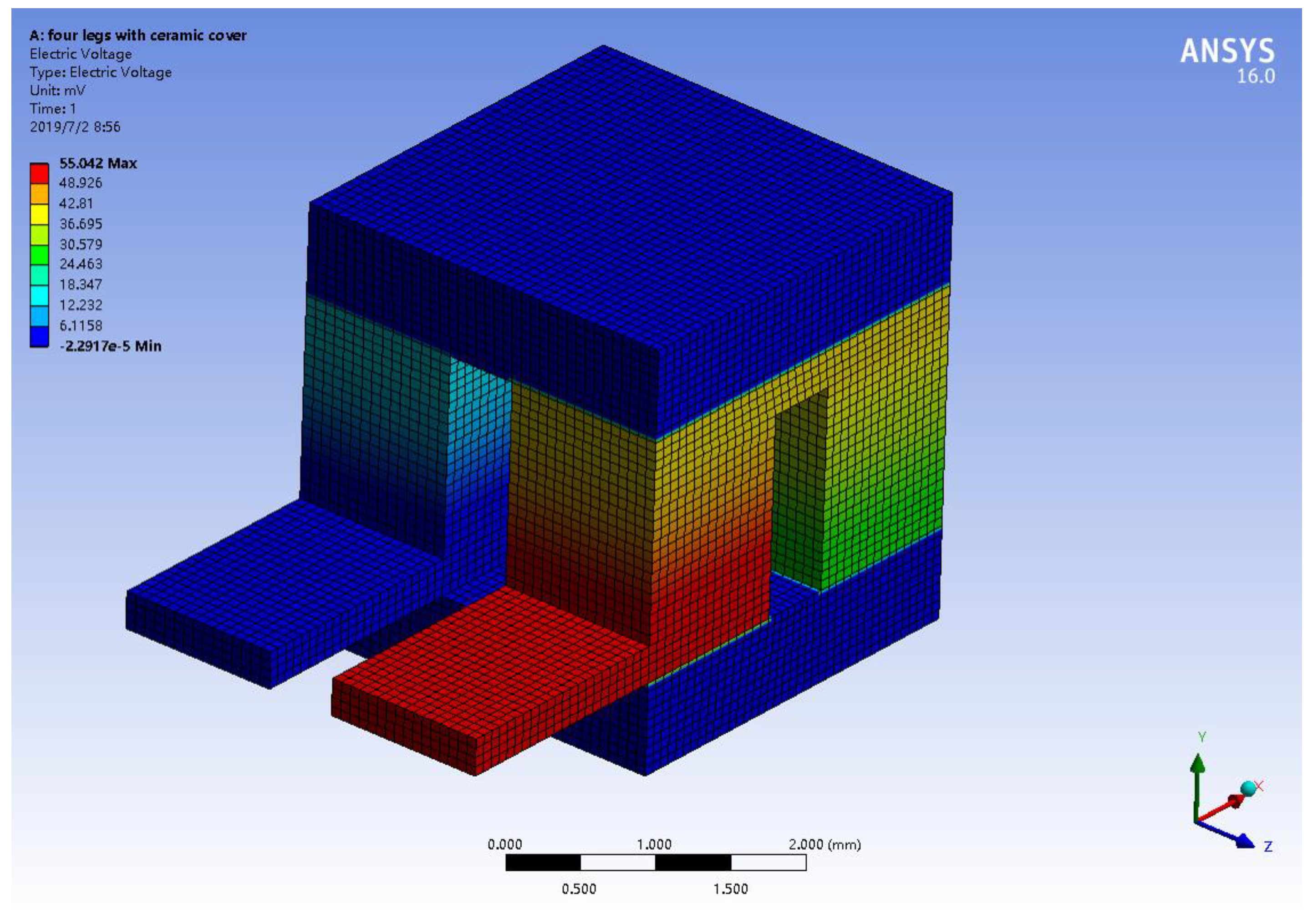
When the top side of the ceramic cover was set as 95 °C and the low side of ceramic cover was set as 20 °C, voltage distribution in the thermoelectric system was shown in Figure 5. The voltage gradually decreased from P leg to N leg and the open-circuit voltage was 55.04 mV. There were only 2 pairs of P/N legs in this numerical model, however, there were 199 pairs of P/N legs in the TEG1-199-1.4-0.5 module. The P/N legs were connected in series in the TEG module. Therefore, the total open-circuit voltage of TEG1-199-1.4-0.5 module was 5.48 V. The open-circuit voltages for various temperature difference can be calculated by changing the temperature boundary condition of upside ceramic cover. The open-circuit voltages were 4.38, 4.75, and 5.11 V at 80, 85, and 90 °C respectively.
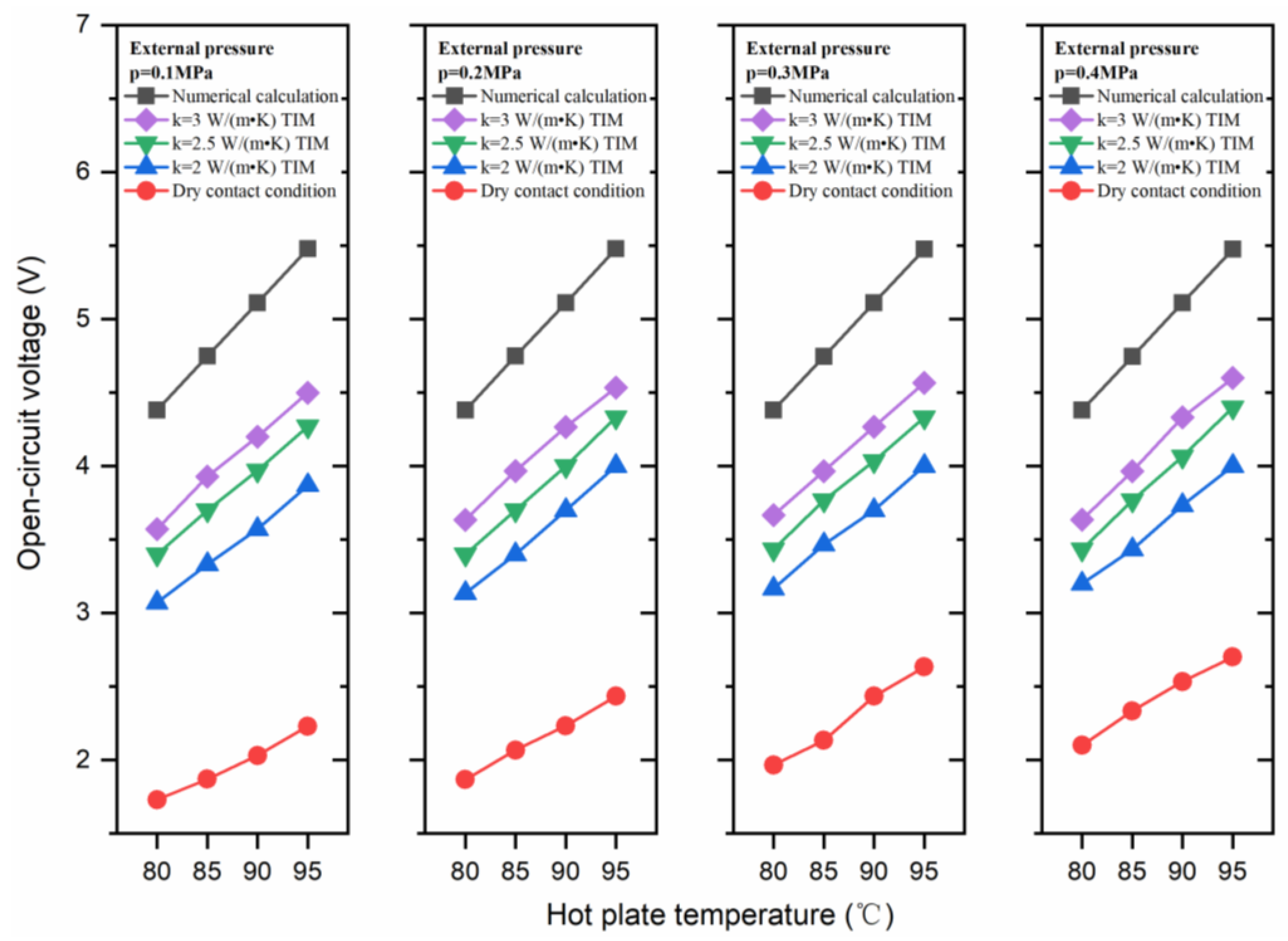
Under the same temperature conditions, the open-circuit voltages of thermoelectric module were experimentally tested. In order to study the effect of interface heat transfer on the performance of thermoelectric module, three kinds of thermal grease with thermal conductivities of 2.0, 2.5, 3.0 W/(m∙K) were used as the thermal interface material and the pressure of compressed air was set at 0.1, 0.2, 0.3, and 0.4 MPa during the testing process. The dry contact condition, which means there was no thermal interface material applied in the contact surface, was also tested. Figure 6 presented the open-circuit voltage output of the module device through experimental measurement and numerical calculation at various temperatures and interface heat transfer conditions.
As shown in Figure 6, at the same interfacial heat transfer condition, the open-circuit voltage linearly increased with the hot-plate temperature. This result is consistent with the conclusion of Equation (2). The temperature of the cold plate was kept at 20 °C during the experiment process. With the increase of hot-plate temperature the temperature difference between the hot and cold side of TEG module increases. Therefore, according to Equation (2), the open-circuit voltage of thermoelectric module increased linearly with the hot-plate temperature. The numerically calculated open-circuit voltages at temperature differences of ΔT = 60, 65, 70, and 75 °C were 4.38, 4.75, 5.11, and 5.48 V, which showed a perfectly linear increase with temperature. According to Figure 6, the open-circuit voltage and temperature difference showed the same trend under different interface heat transfer conditions.
The numerically calculated open voltage was the largest. During the boundary setting process, the temperatures of hot and cold surfaces of thermoelectric module were set equally to the temperatures of hot and cold plates respectively, which means there was no contact resistance between the hot and cold plates and surfaces of the thermoelectric module. Therefore, the temperature difference between the hot and cold sides of the thermoelectric module was the largest in this numerical calculation condition. The generated open-circuit voltage was also the largest.
The open voltage at dry contact condition was the lowest. Although the temperatures of the hot and cold plates were the same during the experiment, there were contact resistance between the hot and cold plates and surfaces of the thermoelectric module. When heat flows through the contacting surfaces, a temperature difference exists between the contacting surfaces. The thermal contact resistance was the largest at the dry contact condition, resulting in the largest temperature difference, which eventually led to the smallest temperature difference between the hot and cold sides of the thermoelectric module. The open-circuit voltages were 1.73, 1.87, 1.97, and 2.1 V at respective temperature differences of ΔT = 60, 65, 70, and 75 °C when the external pressure was 0.1 MPa. Compared with numerically calculated value, the open-circuit voltage decreased by 60.5%, 60.6%, 61.4%, and 61.7% at temperature differences of ΔT = 60, 65, 70, and 75 °C, respectively.
In the cases where thermal grease was used as the thermal interface material, the generated open-circuit voltages were between dry contact conditions and simulation calculation. When thermal greases were used as the thermal interface material, the interfacial heat transfer was enhanced as compared with the dry contact condition. Therefore, the open-circuit voltage increased. Taking external pressure at 0.1 MPa for example, compared with dry contact conditions the open-circuit voltage increased from 1.73, 1.87, 2.03, and 2.23 V to 3.07, 3.33, 3.57, and 3.87 V when k = 2.0 W/(m∙K) thermal grease was used as TIM at temperature differences of ΔT = 60, 65, 70, and 75 °C, respectively. The open-circuit voltages increased by 77.5%, 78.1%, 75.9%, and 73.5%, respectively.
The open-circuit voltages increased with the increase of thermal conductivity of thermal greases when the external pressure and hot-plate temperature were fixed. The higher the thermal conductivities of thermal greases, the stronger their ability to strengthen heat transfer across the contacting interface, thus increasing the temperature difference between the hot and cold sides of the thermoelectric module. Taking hot-side temperature at 80 °C and external pressure at 0.1 MPa for example, the open-circuit voltages were 3.07, 3.4, and 3.57 V when k = 2.0, 2.5, and 3.0 W/(m∙K) thermal greases were used as TIMs, respectively.

3.1.2. Effect of Thermal Greases on Output Power

The output power of TEG module was affected by open-circuit voltage, electrical resistance of the TEG module, and external electrical resistance, and it can be calculated by Equation (3).
P = ( U R i n + R e x ) 2 × R e x ,
where P is the output power of TEG module (W), Rin is the electrical resistance of the TEG module (Ω), Rex is the external electrical resistance (Ω), and U is the open-circuit voltage (V).
The internal electrical resistance and open-circuit voltage were constant when the TEG module and experimental temperatures were determined. At this time, the output power of TEG module was determined by external electrical resistance. By calculating the maximum value of Equation (3), the maximum output power of TEG module can be obtained when the external electrical resistance equaled to the internal electrical resistance. The maximum output power can be calculated by Equation (4).
P M A X = U 2 4 R i n ,
where PMAX is the output power of TEG module (W), Rin is the electrical resistance of the TEG module (Ω), U is the open-circuit voltage (V).
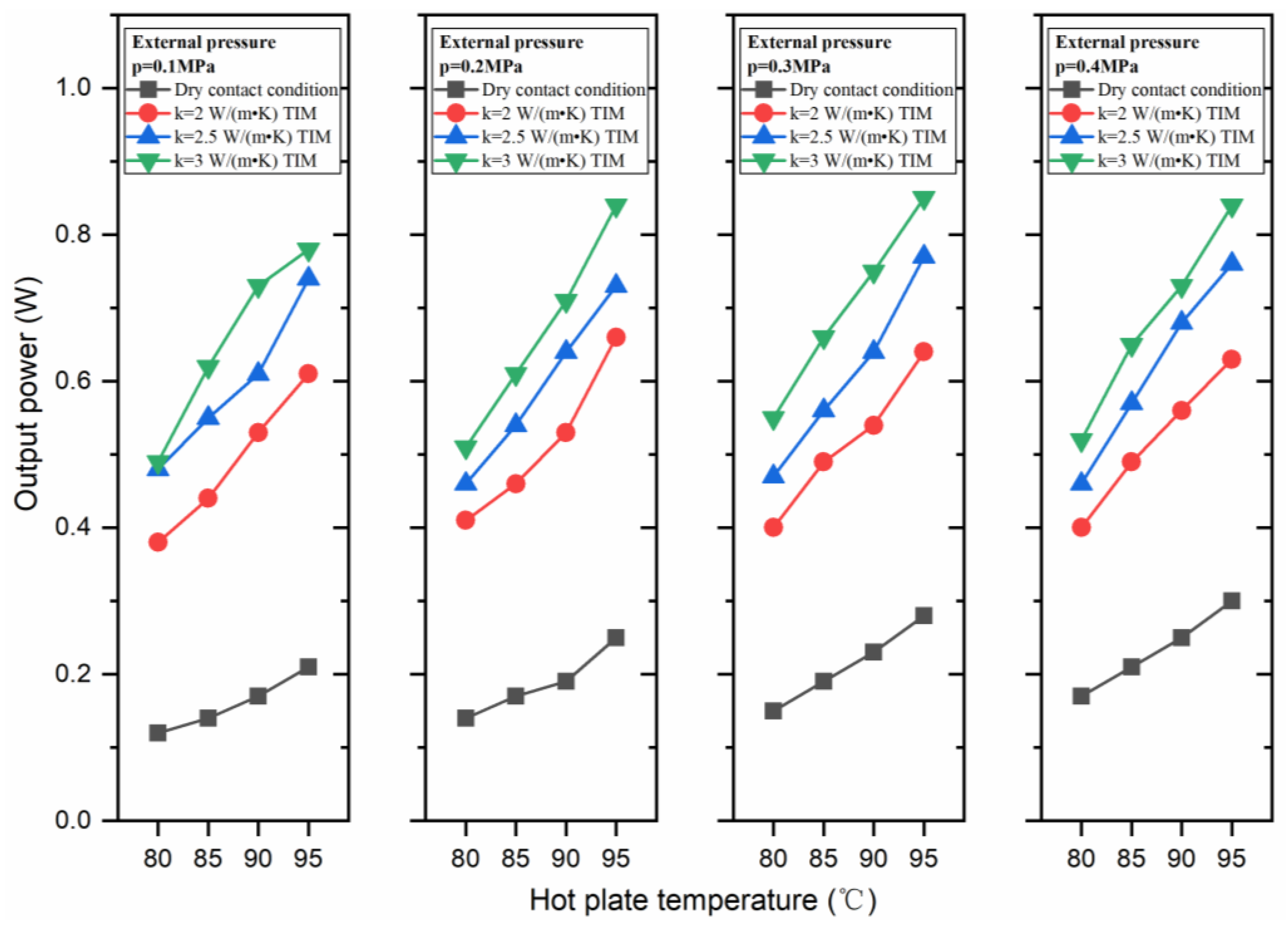
The measured electrical resistance of TEG module was 3.1 Ω. in order to get the maximum output power, the external electrical resistance was set at 3.1 Ω by a slide rheostat. The output power of TEG module is shown in Figure 7.
As shown in Figure 7, the output power of TEG module also increased with the temperature difference. According to Equation (4), the output power of TEG module should have a square relationship with the temperature difference. However, some of the curves do not show quadratic behavior. This phenomena may be caused by the temperature dependency of the Seebeck coefficient [31] or insufficient experimental data.
The output powers of TEG module at dry contact condition were the lowest at all external pressure conditions. This phenomenon was also caused by the poor interfacial heat transfer across the contacting interfaces. The output powers were 0.12, 0.14, 0.17, and 0.21 W at temperature differences of ΔT = 60, 65, 70, and 75 °C when the external pressure was 0.1 MPa, while the output power increased dramatically with the use of thermal grease as thermal interface material. The output powers were 0.38, 0.44, 0.53, and 0.61 W at temperature differences of ΔT = 60, 65, 70, and 75 °C when the external pressure was 0.1 MPa and k = 2.0 W/(m∙K) thermal grease was used as TIM. The rates of increase were 216.7%, 214.3%, 211.8%, and 190.5%, respectively.
Furthermore, the output power also increased with the increase of thermal conductivities of thermal greases. Taking hot-side temperature at 80 °C and external pressure at 0.1 MPa, for example, the open-circuit voltages were 0.38, 0.48, and 0.49 V when k = 2.0, 2.5 and 3.0 W/(m∙K) thermal greases were used as TIMs, respectively.

3.2. The Effect of External Load on Open-Circuit Voltage and Output Power of TEG Module

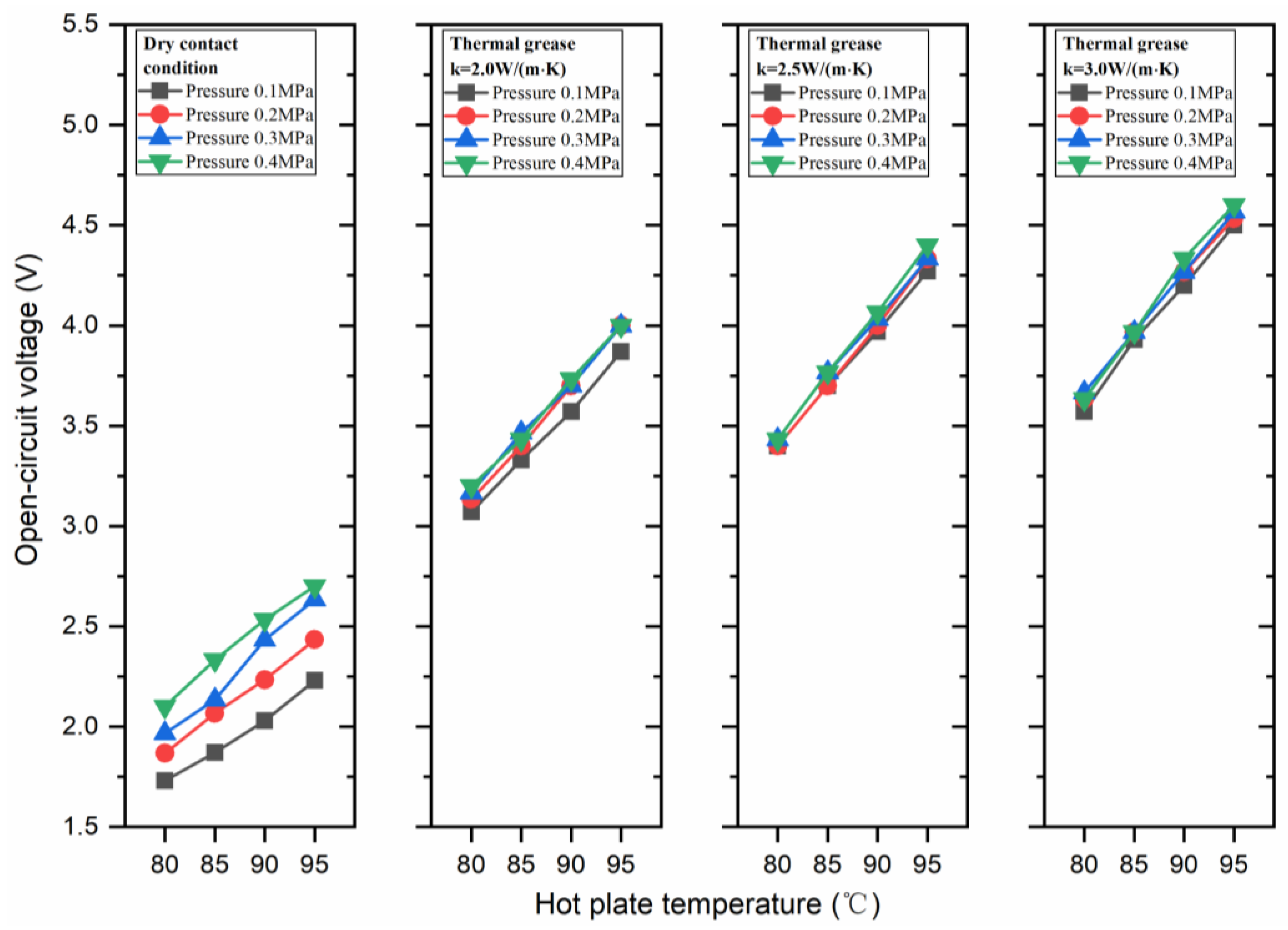
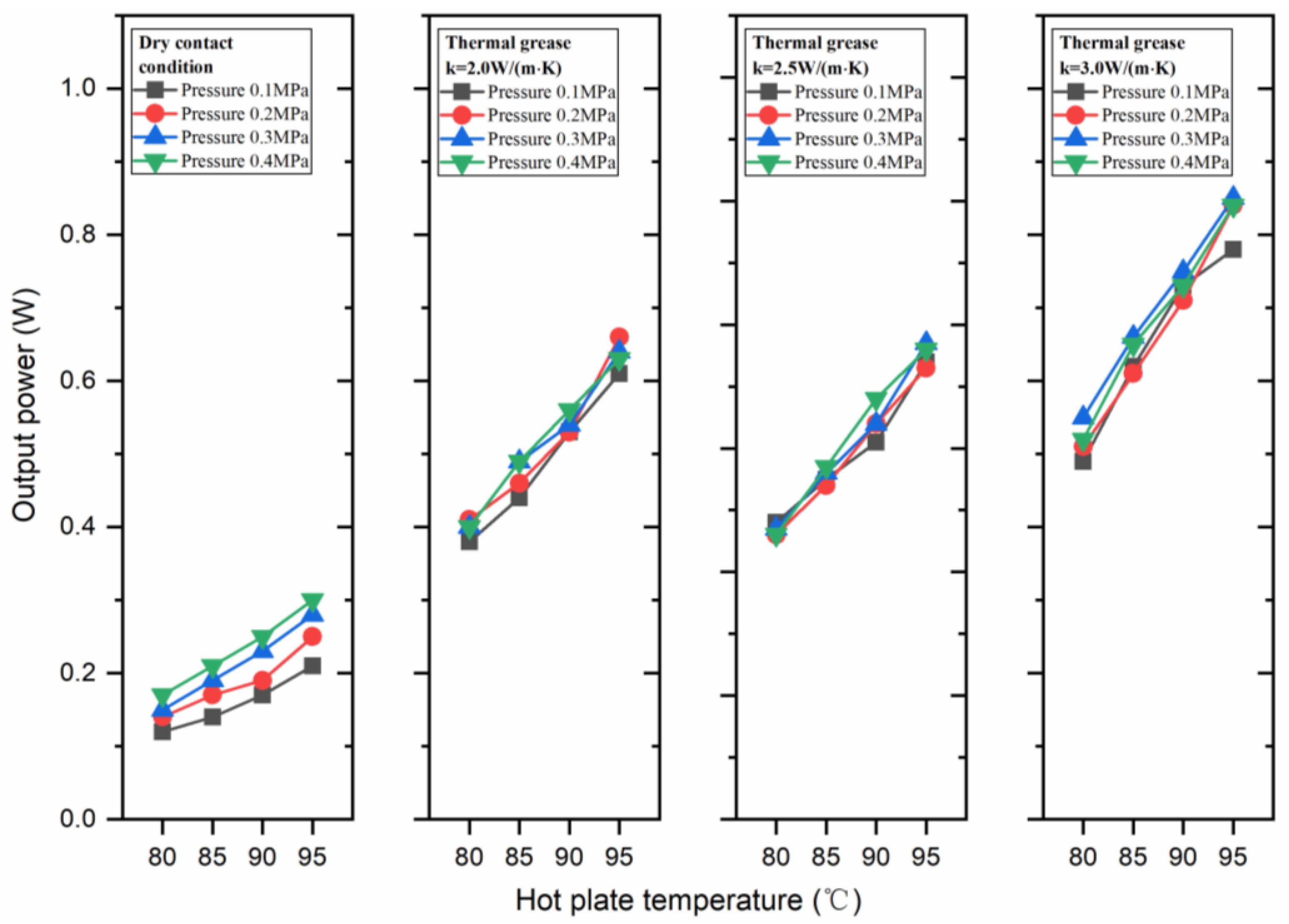
The effect of external loads on the open-circuit voltage and output power at different temperatures of hot plate and thermal interface material are shown in Figure 8 and Figure 9. The generated open-circuit voltages and output powers increased with the increase of external loads at dry contact condition. For dry contact condition, when the temperature difference ΔT = 60 °C, the open-circuit voltages were 1.73, 1.87, 1.97, and 2.1 V at external pressures of 0.1, 0.2, 0.3, and 0.4 MPa, respectively. The corresponding output powers were 0.12, 0.14, 0.15, and 0.17 W at external pressures of 0.1, 0.2, 0.3, and 0.4 MPa, respectively. The open-circuit voltage and output power showed the same increase trend when the temperature differences of ΔT = 65, 70, and 75 °C.
Different from the dry contact condition, the open-circuit voltage and output power almost remained the same with the increase of external pressures when thermal greases were used as TIMs. When thermal greases were used as thermal interface material and smeared between contacting surfaces, the microgaps between the two contacting surfaces were filled with thermal grease, leading to the great increase of actual contact area. Due to the good wettability between thermal grease and the contacting solid surfaces, the microgaps between the contacting surfaces were filled with thermal grease under low external pressure. Taking hot-side temperature at 80 °C and k = 2.0 W/(m∙K) thermal grease was used as TIM for example, the open-circuit voltages were 3.07, 3.13, 3.17, and 3.20 V at external pressures of 0.1, 0.2, 0.3, and 0.4 MPa, respectively. For every 0.1 MPa increase of external pressure, the open-circuit voltage increased by 2.0%, 1.3%, and 0.9%, respectively. It can be seen that the open-circuit voltage was slightly affected by external pressures, and the higher the pressure, the smaller the growth rate. At the same experimental condition, the output powers were 0.38, 0.41, 0.40, and 0.40 W at external pressures of 0.1, 0.2, 0.3, and 0.4 MPa, respectively.
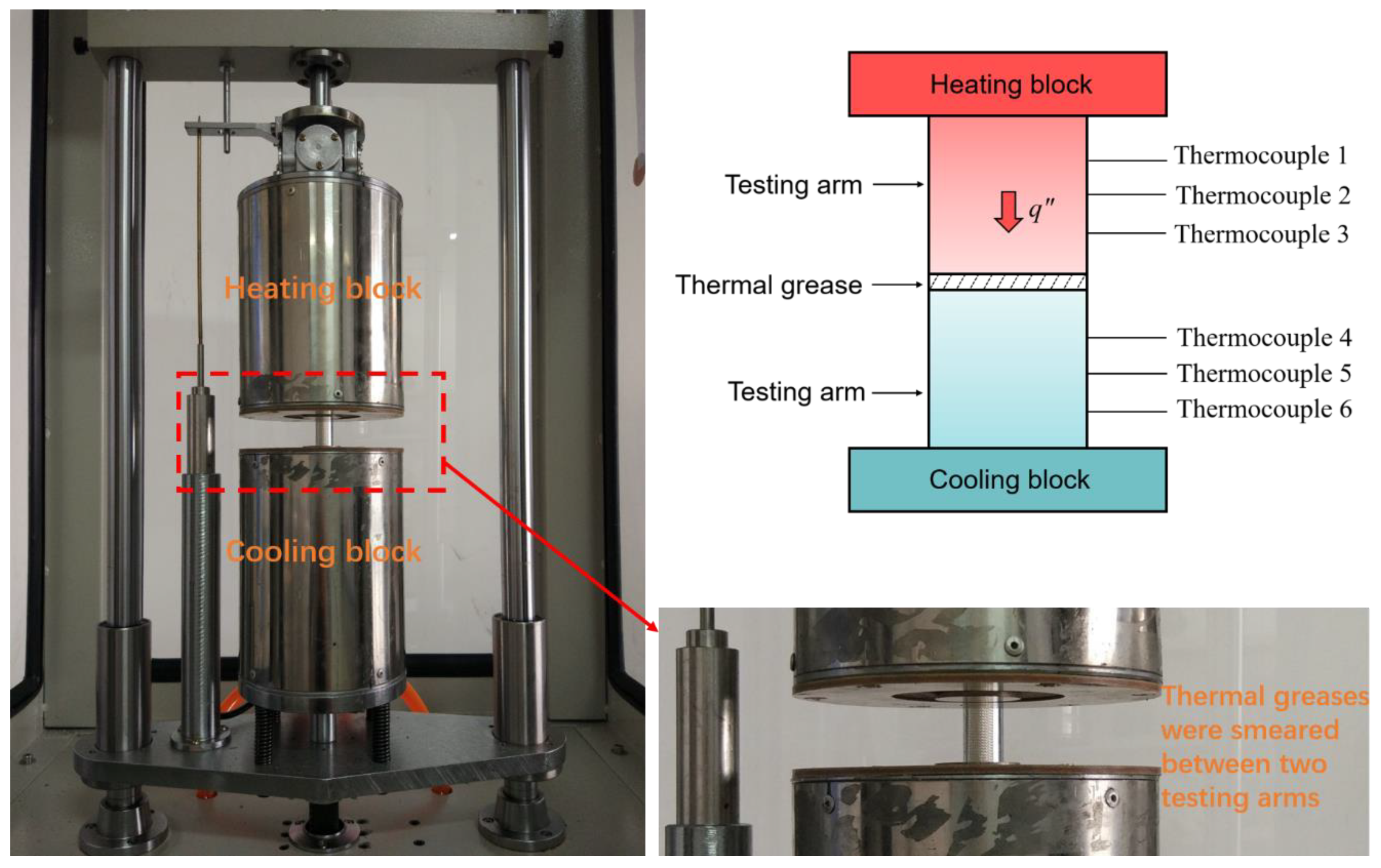
The thermal interfacial resistances between TEG chips and cold and hot plates at different external pressures and use of different thermal greases were measured by DRL-III steady state device (Manufactured by Xiangtan Xiangyi Instrument Co., Ltd. Xiangtan National HIGH-TECH Zone, Hunan Province, China ). The working principle of the DRL-III steady state device is shown in Figure 10. It is mainly composed of a heating block, cooling block, and two testing arms. Thermal greases were smeared to the end faces of the two testing arms to assess the thermal interfacial resistance at different external pressure. Since the thermal interfacial resistances were not affected by the measurement temperature in a small temperature range (80–95 °C) the hot- and cold-side temperatures were respectively set at 90 and 20 °C during the testing. The measured thermal interfacial resistances at different external pressures with thermal greases used as thermal interface material are shown in Figure 11.
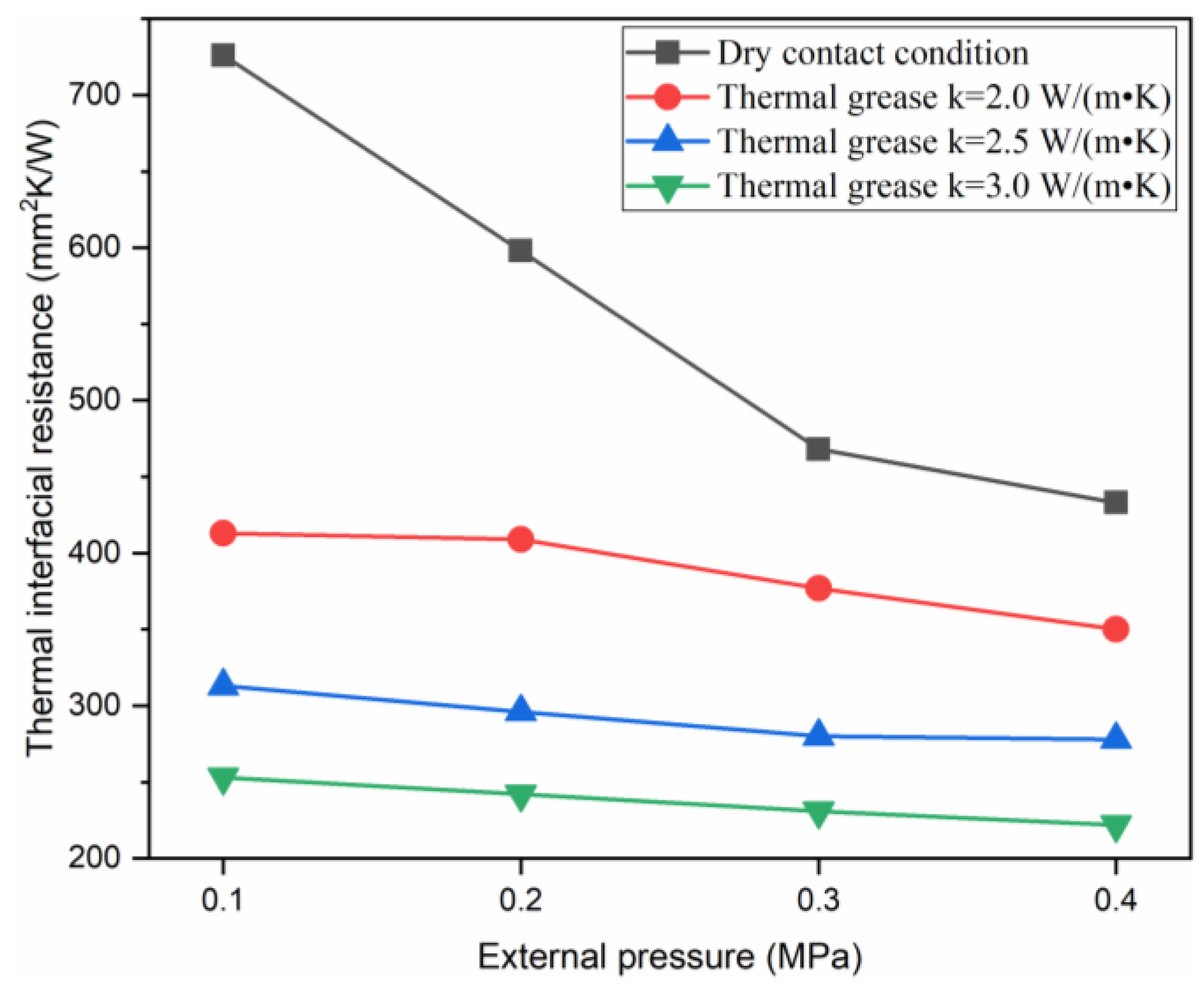
As shown in Figure 11, the thermal interfacial resistance of dry contact condition was the highest at different external pressures. The thermal interfacial resistance decreased dramatically when thermal greases were used as thermal interface material. Furthermore, with increases of the thermal conductivity of thermal grease, the thermal interfacial resistance can be further decreased. External pressures had great effect on thermal interfacial resistance in dry contact condition. The thermal resistance decreased dramatically from 726 to 433 mm2 K/W with the increase of external pressure from 0.1 to 0.4 MPa, and the decrease ratio was 40.4%. Meanwhile, when thermal greases were used as thermal interface material, the thermal interfacial resistance slightly decreased with the increase of external pressure. The thermal interfacial resistance decreased from 413 to 315 mm2 K/W, 313 to 278 mm2 K/W, and 253 to 222 mm2 K/W respectively for k = 2.0, 2.5, and 3.0 W/(m∙K) thermal greases used as TIMs with the increase of external pressure from 0.1 to 0.4 MPa. The corresponding decrease ratios were 15.3%, 11.2%, and 12.3%, respectively.

4. Conclusions

In order to study the effect of interface heat transfer on the power generation efficiency of thermoelectric modules, the corresponding experimental measurements were carried out. Based on the measurement results, the following conclusions can be drawn.
  • The open-circuit voltage and output power were significantly increased at different temperatures when thermal greases were used as thermal interface materials. The open-circuit voltage increased from 1.73 to either 3.07, 3.4, or 3.57 V with k = 2.0, 2.5 and 3.0 W/(m∙K) thermal greases respectively used as TIMs when the temperature difference was 60 °C and external pressure was 0.1 MPa. The corresponding output power increased from 0.12 to either 0.38, 0.48, or 0.49 W, respectively.
  • The external pressure had a great effect on the performance of the TEG module in dry contact condition. The open-circuit voltages were 1.73, 1.87, 1.97, and 2.1 V at external pressures of 0.1, 0.2, 0.3, and 0.4 MPa when the temperature difference ΔT = 60 °C. The corresponding output powers were 0.12, 0.14, 0.15, and 0.17 W, respectively. The thermal resistance decreased dramatically from 726 to 433 mm2 K/W with the increase of external pressure from 0.1 to 0.4 MPa. The decrease ratio was 40.4%.
  • The performance of TEG module was slightly affected by external pressure when thermal greases were used as thermal interface material. The open-circuit voltages were 3.07, 3.13, 3.17, and 3.20 V at external pressures of 0.1, 0.2, 0.3, and 0.4 MPa when the temperature difference ΔT = 60 °C and k = 2.0 W/(m∙K) thermal greases were used as TIMs. The corresponding output powers were 0.38, 0.41, 0.40, and 0.40 W, respectively. The thermal interfacial resistance decreased from 413 to 315 mm2K/W with the increase of external pressure from 0.1 to 0.4 MPa. The decrease ratio was 15.3%.

Author Contributions

Conceptualization, G.L. and Z.W.; Data curation, S.L.; Formal analysis, G.L.; Funding acquisition, Z.W.; Investigation, X.W. and M.X.; Methodology, G.L. and Z.W.; Project administration, Z.W.; Resources, Z.W.; Software, G.L. and F.W.; Supervision, Z.W.; Validation, S.L.; Visualization, F.W.; Writing—original draft, G.L. and Z.W.; Writing—review & editing, Z.W.

Funding

This research was funded by International cooperation project of Shanghai science and technology commission, grant number 17170712100.

Conflicts of Interest

The authors declare no conflict of interest.

References

  1. Yu, C.; Chau, K.T. Thermoelectric automotive waste heat energy recovery using maximum power point tracking. Energy Convers. Manag. 2009, 50, 1506–1512. [Google Scholar] [CrossRef]
  2. Talom, H.L.; Beyene, A. Heat recovery from automotive engine. Appl. Therm. Eng. 2009, 29, 439–444. [Google Scholar] [CrossRef]
  3. Bell, L.E. Cooling, Heating, Generating Power, and Recovering Waste Heat with Thermoelectric Systems. Science 2008, 321, 1457. [Google Scholar] [CrossRef] [PubMed]
  4. Zhao, Y.; Wang, S.; Ge, M.; Li, Y.; Liang, Z.; Yang, Y. Performance analysis of a thermoelectric generator applied to wet flue gas waste heat recovery. Appl. Energy 2018, 228, 2080–2089. [Google Scholar] [CrossRef]
  5. Riffat, S.B.; Ma, X. Thermoelectrics: A review of present and potential applications. Appl. Therm. Eng. 2003, 23, 913–935. [Google Scholar] [CrossRef]
  6. Li, G.; Shittu, S.; Diallo, T.M.O.; Yu, M.; Zhao, X.; Ji, J. A review of solar photovoltaic-thermoelectric hybrid system for electricity generation. Energy 2018, 158, 41–58. [Google Scholar] [CrossRef]
  7. Hadjistassou, C.; Kyriakides, E.; Georgiou, J. Designing high efficiency segmented thermoelectric generators. Energy Convers. Manag. 2013, 66, 165–172. [Google Scholar] [CrossRef]
  8. Ouyang, Z.; Li, D. Modelling of segmented high-performance thermoelectric generators with effects of thermal radiation, electrical and thermal contact resistances. Sci. Rep. 2016, 6, 24123. [Google Scholar] [CrossRef] [PubMed]
  9. Domínguez-Adame, F.; Martín-González, M.; Sánchez, D.; Cantarero, A. Nanowires: A route to efficient thermoelectric devices. Phys. E 2019, 113, 213–225. [Google Scholar] [CrossRef] [Green Version]
  10. Chen, Z.-G.; Han, G.; Yang, L.; Cheng, L.; Zou, J. Nanostructured thermoelectric materials: Current research and future challenge. Prog. Nat. Sci. Mater. Int. 2012, 22, 535–549. [Google Scholar] [CrossRef] [Green Version]
  11. Dimaggio, E.; Pennelli, G. Planar and vertical nanostructures for thermoelectric generation. Mater. Today Proc. 2019, 8, 600–606. [Google Scholar] [CrossRef]
  12. Dura, O.J.; Andujar, R.; Falmbigl, M.; Rogl, P.; López de la Torre, M.A.; Bauer, E. The effect of nanostructure on the thermoelectric figure-of-merit of La0.875Sr0.125CoO3. J. Alloy. Compd. 2017, 711, 381–386. [Google Scholar] [CrossRef]
  13. Cao, Q.; Luan, W.; Wang, T. Performance enhancement of heat pipes assisted thermoelectric generator for automobile exhaust heat recovery. Appl. Therm. Eng. 2018, 130, 1472–1479. [Google Scholar] [CrossRef]
  14. Demir, M.E.; Dincer, I. Performance assessment of a thermoelectric generator applied to exhaust waste heat recovery. Appl. Therm. Eng. 2017, 120, 694–707. [Google Scholar] [CrossRef]
  15. Ma, X.; Shu, G.; Tian, H.; Yang, H.; Chen, T. Optimization of length ratio in segmented thermoelectric generators for engine’s waste heat recovery. Energy Procedia 2019, 158, 583–588. [Google Scholar] [CrossRef]
  16. Meng, J.-H.; Wang, X.-D.; Chen, W.-H. Performance investigation and design optimization of a thermoelectric generator applied in automobile exhaust waste heat recovery. Energy Convers. Manag. 2016, 120, 71–80. [Google Scholar] [CrossRef]
  17. Zhao, Y.; Wang, S.; Ge, M.; Liang, Z.; Liang, Y.; Li, Y. Performance investigation of an intermediate fluid thermoelectric generator for automobile exhaust waste heat recovery. Appl. Energy 2019, 239, 425–433. [Google Scholar] [CrossRef]
  18. Patil, D.S.; Arakerimath, R.R.; Walke, P.V. Thermoelectric materials and heat exchangers for power generation—A review. Renew. Sustain. Energy Rev. 2018, 95, 1–22. [Google Scholar] [CrossRef]
  19. Lu, C.; Wang, S.; Chen, C.; Li, Y. Effects of heat enhancement for exhaust heat exchanger on the performance of thermoelectric generator. Appl. Therm. Eng. 2015, 89, 270–279. [Google Scholar] [CrossRef]
  20. Tzeng, S.-C.; Jeng, T.-M.; Lin, Y.-L. Parametric study of heat-transfer design on the thermoelectric generator system. Int. Commun. Heat Mass Transf. 2014, 52, 97–105. [Google Scholar] [CrossRef]
  21. Wang, Y.; Li, S.; Xie, X.; Deng, Y.; Liu, X.; Su, C. Performance evaluation of an automotive thermoelectric generator with inserted fins or dimpled-surface hot heat exchanger. Appl. Energy 2018, 218, 391–401. [Google Scholar] [CrossRef]
  22. Lesage, F.J.; Sempels, É.V.; Lalande-Bertrand, N. A study on heat transfer enhancement using flow channel inserts for thermoelectric power generation. Energy Convers. Manag. 2013, 75, 532–541. [Google Scholar] [CrossRef]
  23. Wang, C.-C.; Hung, C.-I.; Chen, W.-H. Design of heat sink for improving the performance of thermoelectric generator using two-stage optimization. Energy 2012, 39, 236–245. [Google Scholar] [CrossRef]
  24. Wang, S.; Xie, T.; Xie, H. Experimental study of the effects of the thermal contact resistance on the performance of thermoelectric generator. Appl. Therm. Eng. 2018, 130, 847–853. [Google Scholar] [CrossRef]
  25. Astrain, D.; Vián, J.G.; Martínez, A.; Rodríguez, A. Study of the influence of heat exchangers’ thermal resistances on a thermoelectric generation system. Energy 2010, 35, 602–610. [Google Scholar] [CrossRef]
  26. Kim, T.Y.; Negash, A.; Cho, G. Direct contact thermoelectric generator (DCTEG): A concept for removing the contact resistance between thermoelectric modules and heat source. Energy Convers. Manag. 2017, 142, 20–27. [Google Scholar] [CrossRef]
  27. Lv, S.; He, W.; Jiang, Q.; Hu, Z.; Liu, X.; Chen, H.; Liu, M. Study of different heat exchange technologies influence on the performance of thermoelectric generators. Energy Convers. Manag. 2018, 156, 167–177. [Google Scholar] [CrossRef]
  28. Yin, E.; Li, Q.; Li, D.; Xuan, Y. Experimental investigation on effects of thermal resistances on a photovoltaic-thermoelectric system integrated with phase change materials. Energy 2019, 169, 172–185. [Google Scholar] [CrossRef]
  29. Yu, X.; Lu, X.; Wang, Q.; Chen, Y.; Ma, T. Parametric study of thermoelectric power generators under large temperature difference conditions. Appl. Therm. Eng. 2018, 144, 647–657. [Google Scholar] [CrossRef]
  30. Wang, L.; Romagnoli, A. Cooling system investigation of thermoelectric generator used for marine waste heat recovery. In Proceedings of the 2016 IEEE 2nd Annual Southern Power Electronics Conference (SPEC), Auckland, New Zealand, 5–8 December 2016; pp. 1–6. [Google Scholar]
  31. Goldsmid, H.J. Bismuth Telluride and Its Alloys as Materials for Thermoelectric Generation. Materials 2014, 7, 2577–2592. [Google Scholar] [CrossRef] [Green Version]
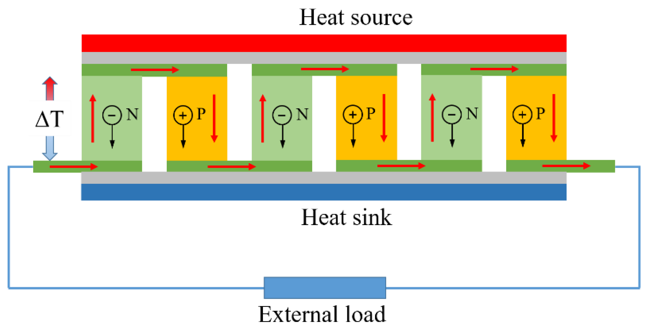
Figure 1. Typical assembly of thermoelectric system.
Energies 12 03797 g001
Figure 2. Numerical modeling of thermoelectric module for ANSYS simulation.
Energies 12 03797 g002
Figure 3. Diagram of experimental system.
Energies 12 03797 g003
Figure 4. Steady state temperature distribution of thermoelectric system.
Energies 12 03797 g004
Figure 5. Voltage distribution in the thermoelectric system.
Energies 12 03797 g005
Figure 6. Effect of using thermal greases with different thermal conductivities as thermal interface material on open-circuit voltage of TEG module.
Energies 12 03797 g006
Figure 7. Effect of using thermal greases with different thermal conductivities as thermal interface material on output power of TEG module.
Energies 12 03797 g007
Figure 8. The open-circuit voltage varies with the external loads at different temperatures of hot plate and thermal interface materials.
Energies 12 03797 g008
Figure 9. The output power varies with the external loads at different temperatures of hot plate and thermal interface materials.
Energies 12 03797 g009
Figure 10. Working principle of DRL-III steady state device used for thermal interfacial resistance measurement.
Energies 12 03797 g010
Figure 11. The thermal interfacial resistance at different external pressures with thermal greases used as thermal interface materials.
Energies 12 03797 g011
Table 1. Physical properties of each component in TEG module package.
ComponentMaterialThermal Conductivity
(Wm−1K−1)
Electrical Resistance
(Ωm)
Seebeck Coefficient
(μVK−1)
Ceramic coverAl2O331--
Copper plateCopper4011.69e−8-
P/N legsBi2Te31.61.18e−5230
Table 2. Specific parameters of the thermoelectric generator (TEG) chip.
ParametersValue
Open-circuit voltage (V)11.1
Matched load resistance (Ω)3.07
Matched load output voltage (V)5.6
Output current (A)1.8
Output Power (W)10
Heat flow through the module (W)192
Heat flux density (W/cm2)12