Article

Improving the Hybrid Electromagnetic Clamping System by Reducing the Leakage Flux and Enhancing the Effective Flux

1
Department of Automotive Engineering, Honam University, 417 Eodeung-daero, Gwangsan-gu, Gwangju 62399, Korea
2
Department of Electrical Engineering, Honam University, 417 Eodeung-daero, Gwangsan-gu, Gwangju 62399, Korea
*
Author to whom correspondence should be addressed.
Energies 2019, 12(19), 3762; https://doi.org/10.3390/en12193762
Submission received: 18 July 2019 / Revised: 23 August 2019 / Accepted: 27 August 2019 / Published: 1 October 2019
(This article belongs to the Section F: Electrical Engineering)

Abstract

:
In most industrial fields, mechanical clamping methods are traditionally used to transport heavy loads such as steel structures by fastening the load using bolts and nuts. However, this method can lead to industrial accidents during load transfer and does not consider the weight of the load. Recently, permanent magnet clamping methods have been proposed to prevent such accidents; for example, hybrid electromagnetic clamping systems (H-EMCSs), which combine permanent magnets and electromagnets and can adjust the clamping force according to the load weight. However, few studies have attempted to improve the electromagnetic structure and effective magnetic flux of H-EMCS. Specifically, H-EMCSs control the clamping force using several hybrid electromagnetic modules (H-EMMs); however, the leakage magnetic flux increases with an increasing number of H-EMMs. Therefore, the clamping force should be improved to avoid increasing the leakage magnetic flux. In this study, we propose a novel H-EMM structure and improve its electromagnetic force characteristics by changing the core shape and dimension effect in order to reduce the leakage flux and maximize the effective magnetic flux. Furthermore, we verify the improved electromagnetic force properties by experimentally validating the proposed model. This research can improve the safe and effective transfer of industrial loads.

Graphical Abstract

1. Introduction

Hybrid electromagnetic clamping systems (H-EMCSs) combine permanent magnets and electromagnets to generate an electromagnetic clamping force for the purpose of fixing or transferring loads in industry [1,2]. The H-EMCS uses neodymium (NdFeB) magnets with a high residual magnetic flux as the main magnetic flux source, which generates the electromagnetic force that is attached to the load. The auxiliary permanent magnets are alnico magnets, whose direction of polarity is easily changed by the external magnetic force [3,4,5]. Therefore, the H-EMCS changes the path of the main magnetic flux according to the polarity direction of the auxiliary permanent magnet to attach and detach the load. The H-EMCS has the advantages of a high electromagnetic force, a short operating time, and easy operation. It is also possible to control the electromagnetic force according to the weight of the load and minimize its size by optimizing the electromagnetic force; therefore, H-EMCSs can be used in confined spaces. An H-EMCS can also improve productivity compared with manual methods that use conventional bolt and nut fastenings, hydraulic drivers, or electromagnets [6,7]. Moreover, an H-EMCS reduces the risk of industrial accidents by replacing conventional mechanical clamping systems with electronic structures [8,9]. Specifically, even if the power supply is shut off, the magnetic force of the permanent magnet is maintained so that the load remains continuously attached to the H-EMCS, preventing the load from falling. Therefore, H-EMCSs are superior to mechanical systems regarding the risk of industrial accidents, power consumption, and device maintenance [10].
However, H-EMCSs use hybrid electromagnetic modules (H-EMMs) to generate the electromagnetic force, which can lead to leakage of the magnetic flux [11,12,13,14], yet few studies have attempted to improve the electromagnetic structure and effective magnetic flux of H-EMCS. Therefore, the objective of this study is to enhance H-EMCS performance by improving the core shape in order to reduce the leakage flux and maximize the effective magnetic flux of H-EMCSs [15,16,17]. This is achieved by modeling the conventional and proposed H-EMCSs using three-dimensional (3D) finite element method (FEM) analysis [18,19]. We review the structure and basic operation principle of H-EMCS and discuss the problems related to H-EMMs. H-EMMs have a magnetic flux path that flows into the lower core and upper core. In order to reduce leakage of this flux between the cores and NdFeB magnets, we suggest a polygonal shape for the lower core. Furthermore, we maximize the effective magnetic flux by determining the influence of upper core dimensions and reducing the thickness of the upper core. To verify the validity of the proposed H-EMCS structure, its performance was compared with the basic H-EMCS using numerical analysis. In addition, a prototype of the proposed model was developed and its performance improvement was verified by comparing experimental and numerical results.

2. Hybrid Electromagnetic Clamping System

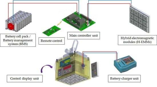
2.1. H-EMCS Structure and Components

Figure 1 shows the configuration of the main components of H-EMCS. The main components consist of a control circuit unit for controlling the electromagnetic force of the H-EMCS, a battery power unit, a battery charging unit, a display unit, and H-EMMs. The H-EMMs are composed of magnetic materials, NdFeB magnets, alnico magnets, and windings. The magnetic flux path of the NdFeB magnets is altered by converting the polarity of the auxiliary permanent magnet using the external magnetic circuit, so that loads can be attached or detached and transported. Therefore, as the number of modules increases, the electromagnetic force also increases. The external magnetic circuit is applied through the battery power supply and the control circuit.

2.2. Electronic Controller and Charging Process

Figure 2 shows the integrated control system, which consists of four main functions (motion, display, control, charger unit). The main function of the integrated control system is to control the strength of the electromagnetic force according to the weight of the load, and perform charge and discharge and battery management system (BMS) functions. In particular, the H-EMCS is important for selecting and configuring optimized BMS specifications. The BMS checks the battery in real time to prevent over-charging and over-discharge and to ensure a uniform voltage. It requires high efficiency battery charging, discharge control, and cell balancing control. Figure 3 shows the flow of the battery charging system in H-EMCS. The charging process uses the external power source to apply the voltage to the charge/discharge system. During charging, the magnitude of the current is measured to determine whether the charging condition is satisfied. External power is supplied until the charging condition is satisfied.

2.3. Design Process of Hybrid Electromagnetic Modules

Figure 4 shows the electromagnetic field analysis process for the design of the H-EMMs. The most important part is the structural design of permanent magnets and electromagnets. In addition, the electromagnetic field analysis calculates the grade of alnico magnets and NdFeB magnets, as well as the winding method, outer diameter of the coil, turns, current density, and magnetic flux density that satisfy the required electromagnetic force. The hysteresis and magnetization sequence are also examined. Moreover, the attachment mode and detachment mode are separated and analyzed. The H-EMMs designed through this process are used to enhance the design specifications through feedback of the analysis results after the performance tests.

2.4. Basic Structure of Conventional Hybrid Electromagnetic Modules

Figure 5 shows the basic H-EMM structure for the electromagnetic field analysis. The H-EMMs are the most important part of the H-EMCS for generating the electromagnetic force. Here, we review the structure and operation principle of conventional H-EMMs, as well as the related problems, and then propose a way to improve H-EMM performance. As shown in Figure 5, the conventional H-EMM model has a 4-to-4 array structure and consists of alnico magnets 16 Ea and NdFeB magnets 40 Ea. The load is a magnetic steel body of material S45C. The amount of the array can be changed according to the magnitude of the electromagnetic force. In this study, we design a 4-by-2 array structure with an electromagnetic force of 1 kNm.
Figure 6 shows the cross-sectional structure of H-EMMs. The basic configuration of H-EMMs consists of NdFeB magnets that constitute the main magnetic flux and alnico magnets that induce polarity in the auxiliary permanent magnets. Between these magnets, there is a magnetic body that serves as a path to the magnetic flux, which consists of an upper core and a lower core. The lower core is the primary magnetic flux path of the NdFeB and alnico magnets, and the upper core is the secondary magnetic flux path in direct contact with the load. A copper coil for changing the polarity surrounds the alnico magnets. The alnico magnet polarity is easily converted by the external magnetic force; that is, the polarity change is altered up and down according to the current application direction of the coil wound on the bobbin, which changes the flow direction of the main magnetic flux. This directional change of the magnetic flux path determines whether the H-EMCS is operating in attach or detach mode. Also, the greater the number of H-EMMs, the greater the attachment power. Table 1 shows the materials and specifications of the H-EMMs.

2.5. Basic Operating Principle of Hybrid Electromagnetic Modules

The H-EMMs can be divided into attachment mode and detachment mode according to the generation of electromagnetic force on the load. In attachment mode, the magnetic flux flows in the load direction and an electromagnetic force is generated. In detachment mode, the electromagnetic force is removed. Figure 7 and Figure 8 show the magnetic flux density of attachment and detachment modes determined by 3D FEM analysis of the conventional H-EMM model. The polarity of the alnico magnets changes according to the applied current of the coil. Depending on the polarity direction of the alnico magnets, the load is attached to or detached from the H-EMMs.

2.5.1. Attachment and Detachment Mode

In attachment mode, the magnetization direction of the alnico magnets located on the lower side is converted and produces magnetic flux that flows towards the upper core. Figure 7 confirms that the electromagnetic force is generated on the load side because the direction of the magnetic flux passes through the load side. In detachment mode, the magnetization direction of the alnico magnets located at the lower side is reversed, so that the magnetic flux flows toward the lower core. As shown in Figure 8, no electromagnetic force is generated because the direction of the magnetic flux does not pass through the load side.

2.5.2. Magnetic Flux Leakage in the Conventional Model

In order to increase the electromagnetic force of the H-EMCS, the amount of H-EMMs should be increased. However, as shown in Figure 9, an increase in the number of H-EMM increases the leakage flux between the cores, which leads to a reduction of the electromagnetic force and reduces system efficiency. It can also lead to accidents such as dropping the load during load transfer. In this study, we analyze the performance of the conventional model and verify the influence of core shape, which acts as the main path of the magnetic flux. We then propose a polygonal core shape to improve the electromagnetic force generated by the H-ECMS.

3. Improving H-EMM Performance through Core Shape Modification

3.1. Conventional Hybrid Electromagnetic Module Model

Figure 10 shows a basic model for analyzing a core shape with a polygonal structure. To shorten the time required for 3D FEM analysis, the modeling was composed of a 2-by-2 array. In order to improve the accuracy of the analysis, we defined a 2 mm thick air region between the load and the upper core. The air region was equally divided into 1 mm intervals when setting the mesh. In addition, the shapes of the alnico magnets and NdFeB magnets and the winding specifications were not specified as design parameters during fabrication. The prototype was fabricated and evaluated in a 4-by-2 array structure. Figure 11 shows the mesh shape before and after element segmentation for the conventional model. A total of 805,671 elements and 139,595 nodes were used for the 3D FEM analysis after element segmentation. The 3D FEM analysis was performed using JMAG-designer (version 17.1, JSOL Corporation, Tokyo, Japan) and the analysis module was used 3D magnetic field static analysis. The nonlinear effect of the material was not considered in the 3D FEM analysis.
Figure 12 shows the flux flow in attachment and detachment modes for the conventional model. The flow of the magnetic flux and distribution of magnetic flux density differed between the two modes. The magnetic flux density of the air region was more than 0.45 T in attachment mode, but less than 0.4 T in detachment mode. The magnitude of the electromagnetic force was 454.8 Nm in attachment mode and 10.5 Nm in detachment mode.

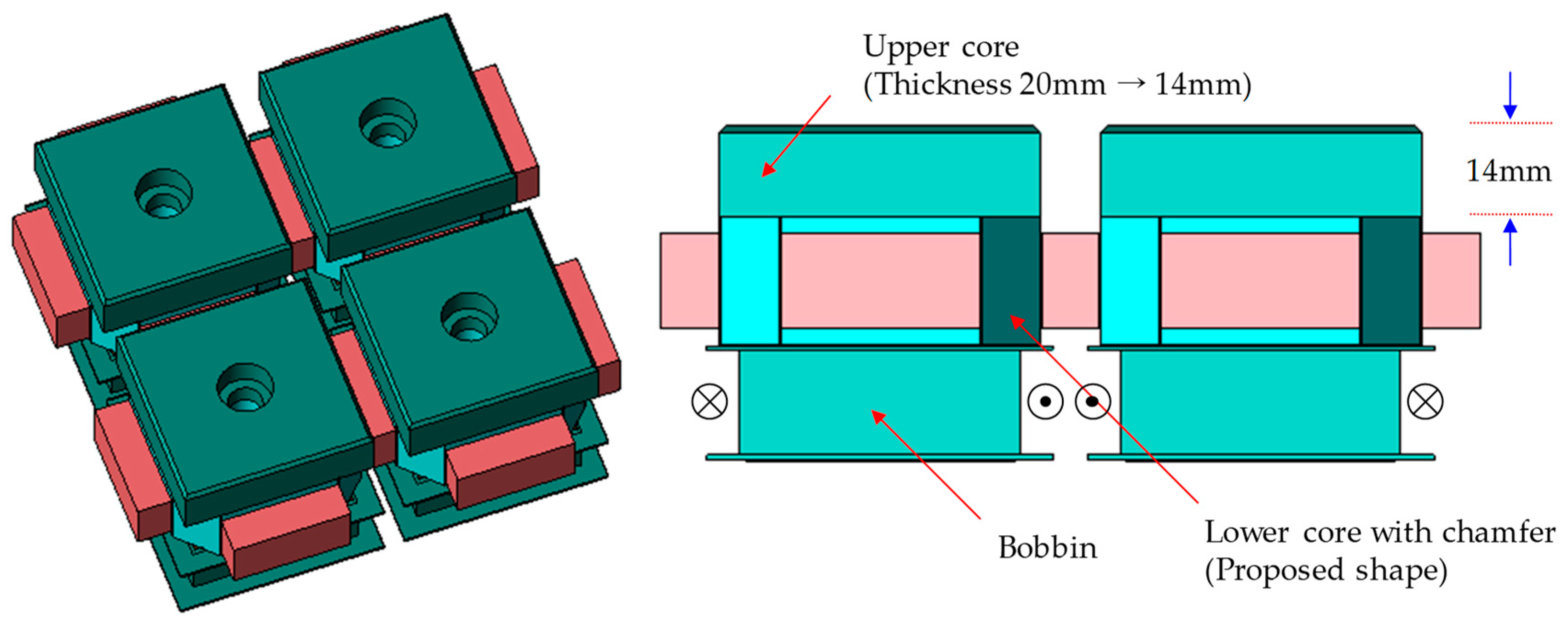
3.2. Proposed Hybrid Electromagnetic Module Model

In this study, we developed a novel H-EMM model by changing the shape of the upper and lower cores. These shape changes were designed to reduce leakage of the magnetic flux and improve H-EMCS performance by minimizing the effective flux path. The size of the NdFeB magnets and alnico magnets and the thickness of the lower core were set as constraints during model assembly (Table 2). The volume of the permanent magnet is the most important factor determining the electromagnetic force. Therefore, the shape of the core was changed while maintaining the same volume of the permanent magnet. The thickness of the lower core was set as a constraint because the NdFeB magnets are attached to the lower core. Moreover, the same height was applied. Three shape modifications were proposed: applying a polygonal structure to the lower core, changing the area of the upper core, and changing the thickness of the upper core. The effects of these modifications on magnetic flux leakage and the effective magnetic flux were analyzed by electromagnetic field analysis.

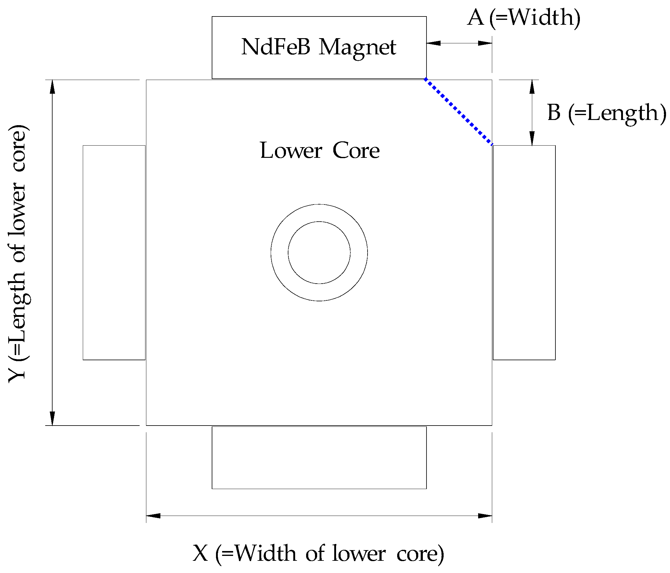
3.2.1. Effect of Changing the Lower Core Shape

Figure 13 shows the change in the shape of the lower core from a quadrilateral structure to a polygonal structure. On the fourth side of the lower core, the NdFeB magnets generating the main magnetic flux are attached. In attachment mode, the main magnetic flux moves in the upper direction so the load is attached to the H-EMMs, and vice versa in detachment mode. When the shape of the lower core is changed to polygonal, the pole distance of the NdFeB magnets is lengthened and the magnetic flux leakage is reduced. Therefore, the effective magnetic flux is increased.
Figure 14 shows the settings of model variables A and B, which are related to the shape of the corners of the lower core. We modeled and analyzed the polygonal structure by chamfering the corners as the variables. Figure 15 shows the H-EMM performance analysis results according to dimensional changes of A and B. The optimal lower core shape change (A and B = 9.3 mm) improved the electromagnetic force in the proposed model by 4.5%, from 454.8 Nm in the conventional model to 475.3 Nm.

3.2.2. Effect of Changing Both Lower and Upper Core Shapes

Figure 16 shows the model where both the upper and lower core shapes are changed. The unit area in contact with the load decreases; therefore, the electromagnetic force decreases by 1.5%, from 454.8 Nm in the conventional model to 448.0 Nm. Although the lower core has no degrees of freedom for x, y, and z, the upper core does. Therefore, it is necessary to determine whether the electromagnetic force can be improved by changing the x, y, and z dimensions of the upper core. Also, considering the bolt tightening, the thickness of the upper core is set from 20 mm to at least 14 mm.

3.2.3. Effect of Changing the Upper Core Dimensions

The electromagnetic force is proportional to the area of contact with the load. Therefore, we analyzed the effect on the electromagnetic force caused by changing the shape of the upper core; that is, width, length, and thickness (Figure 17). It can be confirmed that the width and length of the conventional model (50 mm) generate the greatest electromagnetic force; however, the electromagnetic force increases when the thickness of the upper core is reduced. This is because it shortens the magnetic path of the effective magnetic flux, increasing the electromagnetic force. The maximum electromagnetic force occurs when the thickness of the upper core is reduced to 14 mm (478.9 Nm), representing a 5.3% improvement from the conventional model.

4. Verification of the Proposed Model

4.1. Simulation Results

In Section 3, we determined the effects of upper and lower core dimensions on leakage of the magnetic flux and the effective magnetic flux. That is, magnetic flux leakage was reduced by chamfering the edges of the lower core; the maximum electromagnetic force was obtained by maintaining the same upper core width and length as the basic model, and the effective flux path was shortened and H-EMM performance was improved by reducing the thickness of the upper core. Therefore, we performed simulations using a model combining these shape modifications (Table 3 and Figure 18). The 3D FEM analysis of the proposed model revealed the contours and vector plots of the magnetic flux density (Figure 19). Table 4 shows a comparison of H-EMM performance for the 2-by-2 and 4-by-2 arrays of the conventional and proposed models. The proposed model increases the electromagnetic force by at least 9.8% compared with the conventional model.

4.2. Experimental Results

The validity of the proposed design was experimentally verified by fabricating a prototype of the proposed H-EMM. The prototype is a 4-by-2 array model based on an electromagnetic force of 1 kNm (Figure 20). Figure 21 shows the evaluation system for the prototype. When power was applied to the prototype, the H-EMM became attached to the load-bed by generating an electromagnetic force. The electromagnetic force was measured by lifting the attached H-EMM in the vertical direction. Table 5 shows a comparison of the electromagnetic force generated by the basic model, the proposed model, and the actual prototype. The numerical and experimental results agree for the proposed model, confirming that the performance is improved from the conventional model. Thus, the shape of the proposed model effectively increases the effective magnetic flux and reduces leakage of the magnetic flux.

5. Conclusions

In this study, we proposed several changes to the core shape of H-EMMs in order to reduce the core leakage flux and maximize the effective magnetic flux of H-EMCS. In H-EMMs, the upper and lower cores serve as the main path of the magnetic flux. In our proposed H-EMM model, the leakage flux was reduced by chamfering the corners of the lower core and the effective magnetic flux was maximized by reducing the thickness of the upper core. A 3D FEM analysis was used to compare the electromagnetic performance of the proposed model with the conventional H-EMM model. The validity of the numerical analysis results was verified by developing and experimentally evaluating a prototype of the proposed H-EMM design. We confirmed that the proposed H-EMM model increased the electromagnetic force by as much as 10.6% compared analytically with the conventional model, and the experimental results of the prototype of the proposed H-EMM are very similar to the analytical results. Through this, we confirmed that the proposed model has the effect of performance improvement. Therefore, we designed and developed an improved H-EMM that reduces magnetic flux leakage, increases the effective magnetic flux, and improves the electromagnetic force characteristics of hybrid electromagnetic clamping systems. This research has important applications for the improved transport of heavy loads in various industries. It can also be used as a method for maximizing effective magnet and reducing leakage magnetic flux in a mechanical clamping system that applies electromagnetic force.

Author Contributions

Conceptualization, K.-Y.Y.; Methodology, K.-Y.Y. and S.-W.B.; Software, K.-Y.Y. and S.B.; Validation, K.-Y.Y. and S.-W.B.; Writing—original draft preparation, S.-W.B.; Writing—review and editing, K.-Y.Y.; Supervision, K.-Y.Y.; Funding acquisition, K.-Y.Y.

Funding

This work was supported by the National Research Foundation of Korea (NRF) grant funded by the Korea government (MSIP; Ministry of Science, ICT & Future Planning) (No. 2017R1C1B5017729).

Conflicts of Interest

The authors declare no conflict of interest.

References

  1. Wanli, C.; Chenglin, G.; Xiaodong, H. Analysis and Design of a Permanent Magnet Bi-Stable Electro-Magnetic Clutch Unit for In-Wheel Electric Vehicle Drives. Energies 2015, 8, 5598–5612. [Google Scholar] [Green Version]
  2. Baek, S.-K.; Oh, H.-K.; Kim, S.-W.; Seo, S.-I. A Clamping Force Performance Evaluation of the Electro Mechanical Brake Using PMSM. Energies 2018, 11, 2876. [Google Scholar] [CrossRef]
  3. Jo, C.; Hwang, S.; Kim, H. Clamping-force control for electromechanical brake. IEEE Trans. Veh. Technol. 2010, 59, 3205–3212. [Google Scholar] [CrossRef]
  4. Lee, Y.O.; Jang, M.; Lee, W.; Lee, C.W.; Chung, C.C.; Son, Y.S. Novel clamping force control for electric parking brake systems. Mechatronics 2011, 21, 1156–1162. [Google Scholar] [CrossRef]
  5. Ki, Y.H.; Lee, K.J.; Cheon, J.S.; Ahn, H.S. Design and implementation of a new clamping force estimator in electro-mechanical brake systems. Int. J. Automot. Technol. 2013, 14, 739–745. [Google Scholar] [CrossRef]
  6. Hemmati, V.E.; Oskouei, R.H.; Chakherlou, T.N. An Experimental Method for Measuring Clamping Force in Bolted Connections and Effect of Bolt Threads Lubrication on its Value. World Acad. Sci. Eng. Technol. Int. J. Mech. Mechatron. Eng. 2008, 2, 1136–1139. [Google Scholar]
  7. Park, G.; Hyun, D.; Choi, S.B. Development of Clamping Force Estimation Algorithm and Clamp-force Sensor Calibration on Electromechanical Brake Systems. Trans. KSAE 2016, 24, 365–371. [Google Scholar] [CrossRef] [Green Version]
  8. Saric, S.; Bab-Hadiashar, A.; Hoseinnezhad, R. Clamp-Force Estimation for a Brake-by-Wire System: A Sensor-Fusion Approach. IEEE Trans. Veh. Technol. 2008, 57, 778–786. [Google Scholar] [CrossRef]
  9. Essam, A.; Bahkali, A. Finite Element Modeling for Thermal Stresses Developed in Riveted and Rivet-Bonded Joints. Int. J. Eng. Technol. IJET IJENS 2011, 11, 106–112. [Google Scholar]
  10. Nah, H.-S.; Lee, H.-J.; Kim, K.-S.; Kim, J.-H.; Kim, W.-B. Method for estimating the clamping force of high strength bolts subjected to temperature variation. Int. J. Steel Struct. 2009, 9, 123–130. [Google Scholar] [CrossRef]
  11. Hrvoje, V.; Željko, S.; Željko, H.; Tin, B. A Transformer with Increased Leakage Flux for Didactic Considerations on Magnetic Circuits. Int. J. Electr. Comput. Eng. Syst. 2017, 8, 27–32. [Google Scholar]
  12. Yoon, M.-H.; Sim, J.-H.; Kim, J.-M.; Lim, M.-S.; Jung, J.-W.; Hong, J.-P. Leakage Flux Reduction Applying Rib-less Structure in V-shape Interior Permanent Magnet Synchronous Motor. J. Magn. 2018, 23, 387–391. [Google Scholar] [CrossRef]
  13. Linshuai, Z.; Shuxiang, G.; Huadong, Y.; Yu, S. Design and principle analysis for electromagnetic brake clamping mechanism of a novel slave manipulator. In Proceedings of the 2016 IEEE International Conference on Mechatronics and Automation, Harbin, China, 7–10 August 2016; pp. 490–495. [Google Scholar]
  14. Luo, M.; Luo, D.; Dujic, J.; Allmeling, J. Leakage flux modelling of multi-winding transformer using permeance magnetic circuit. In Proceedings of the 2016 IEEE Applied Power Electronics Conference and Exposition, Long Beach, CA, USA, 20–24 March 2016; pp. 1108–1114. [Google Scholar]
  15. Ma, J.; Qu, R.; Li, J.; Jia, S. Structural Optimization of a Permanent-Magnet Direct-Drive Generator Considering Eccentric Electromagnetic Force. IEEE Trans. Magn. 2015, 51, 8100904. [Google Scholar] [CrossRef]
  16. Liangliang, W.; Baichao, C.; Yushun, L.; Cuihua, T.; Jiaxin, Y.; Yuxin, B.; Tianan, Z. Performance Investigation and Optimization of a Novel Hybrid Saturated-Core Fault-Current Limiter Considering the Leakage Effect. Energies 2018, 11, 61. [Google Scholar] [Green Version]
  17. Caiyan, Q.; Chaoning, Z.; Haiyan, L. H-Shaped Multiple Linear Motor Drive Platform Control System Design Based on an Inverse System Method. Energies 2017, 10, 1990. [Google Scholar] [Green Version]
  18. Woo, K.I.; Kwon, B.I. Characteristic analysis and modification of PM-type magnetic circuit breaker. IEEE Trans. Magn. 2004, 40, 691–694. [Google Scholar] [CrossRef]
  19. Felipe, T.; Marilia, A.S.; Aly, F.F.; David, G.D. Theoretical and Experimental Analysis of an Induction Planar Actuator with Different Secondaries. Sensors 2016, 16, 407. [Google Scholar]
Figure 1. Configuration and major components of the hybrid electromagnetic clamping system (H-EMCS).
Energies 12 03762 g001
Figure 2. Integrated control system for the H-EMCS.
Energies 12 03762 g002
Figure 3. Charging process of the H-EMCS.
Energies 12 03762 g003
Figure 4. Design process for electromagnetic structure of H-EMMs.
Energies 12 03762 g004
Figure 5. Basic structure of conventional H-EMMs. NdFeB, neodymium.
Energies 12 03762 g005
Figure 6. Cross-sectional structure of conventional H-EMMs.
Energies 12 03762 g006
Figure 7. Magnetic flux density of the H-EMMs in attachment mode.
Energies 12 03762 g007
Figure 8. Magnetic flux density of the H-EMMs in detachment mode.
Energies 12 03762 g008
Figure 9. Leakage flux between upper and lower cores surrounding the H-EMMs.
Energies 12 03762 g009
Figure 10. Model of the conventional H-EMM.
Energies 12 03762 g010
Figure 11. Mesh shape in the conventional model (a) before mesh; (b) after mesh.
Energies 12 03762 g011
Figure 12. Magnetic flux density of H-EMMs in (a) attachment mode; (b) detachment mode.
Energies 12 03762 g012
Figure 13. Model showing the polygonal structure applied to the lower core.
Energies 12 03762 g013
Figure 14. Schematic of variables A and B related to the corner shape of the lower core.
Energies 12 03762 g014
Figure 15. H-EMM performance analysis results according to the shape change of the lower core.
Energies 12 03762 g015
Figure 16. Model showing the polygonal structure applied to both lower and upper cores.
Energies 12 03762 g016
Figure 17. H-EMM performance results according to (a) upper core width and length; (b) upper core thickness.
Energies 12 03762 g017
Figure 18. Model of the proposed H-EMM combining all shape modifications.
Energies 12 03762 g018
Figure 19. Magnetic flux density of the proposed model: (a) contour plots and (b) vector plots.
Energies 12 03762 g019
Figure 20. Prototype of the proposed model: (a) upper view; (b) bottom view.
Energies 12 03762 g020
Figure 21. Evaluation system for the prototype H-EMM model.
Energies 12 03762 g021
Table 1. Specifications of the hybrid electromagnetic modules (H-EMMs). NdFeB, neodymium.
ItemsValue-
WindingMaterialCopperΦ1.0mm, 20turns
MagnetAlnicoGradeAlnico5Br 1.1 (T)
NdFeBGradeN38Br 1.3 (T)
CoreUpperMaterialS45CMagnetic steel
LowerMaterialS45C
Table 2. Constraints used in the 3D FEM model.
PartsUnitSizeDescription
MagnetNdFeBmm31, 16, 9 twidth, length, thickness
(all dimensions are fixed)
Alnicomm42, 42, 18 t
CoreUppermm50, 50, 20 twidth (x), length (y), thickness (z)
(all dimensions are variable)
Lowermm50, 50, 20 twidth (x), length (y), thickness (z)
(width and length are variable)
t: Magnetization thickness of permanent magnet.
Table 3. Dimensional changes of the upper and lower cores in the proposed model.
PartsUnitConventional ModelProposed Model
Lower coreCornerAmm09.3
Bmm09.3
z (thickness)mm2020
Upper corex (width)mm5050
y (length)mm5050
z (thickness)mm2014
Table 4. Comparison of electromagnetic force by array quantity of basic model and proposed model.
ArrayUnitElectromagnetic Force
Basic ModelProposed ModelRate
2-by-2Nm454.8499.89.8% ↑
4-by-2Nm907.81003.810.6% ↑
Table 5. Performance comparison between the conventional model, proposed model, and the prototype with the proposed design.
4-by-2 ArraySimulationExperiment
Basic ModelProposed ModelBasic ModelProposed Model
Electromagnetic force (Nm)907.81003.8 (10.6% ↑)-997.5

