Article

Polymer Gels Made with Functionalized Organo-Silica Nanomaterials for Conformance Control

1
Deptment of Geoscience and Petroleum, Norwegian University of Science and Technology, 7031 Trondheim, Norway
2
Deptment of Mathematical Sciences, Norwegian University of Science and Technology, 7034 Trondheim, Norway
3
Petroleum Department, SINTEF Industry, 7031 Trondheim, Norway
4
Materials and Nanotechnology Department, SINTEF Industry, 0373 Oslo, Norway
*
Author to whom correspondence should be addressed.
Energies 2019, 12(19), 3758; https://doi.org/10.3390/en12193758
Submission received: 12 September 2019 / Revised: 23 September 2019 / Accepted: 27 September 2019 / Published: 30 September 2019
(This article belongs to the Special Issue Enhanced Oil Recovery 2020)

Abstract

:
Deep placement of gel in waterflooded hydrocarbon reservoirs may block channels with high water flow and may divert the water into other parts of the reservoir, resulting in higher oil production. In order to get the gel constituents to the right reservoir depths, a delay in the gelling time in the order of weeks at elevated temperatures will be necessary. In this work, a methodology for controlled gelation of partially hydrolyzed polyacrylamide using hybrid nanomaterials with functional groups as cross-linkers was developed. Two delay mechanisms with hybrid materials and polyelectrolyte complexes were designed and tested. Both mechanisms could significantly delay the gelation rate, giving gelling times ranging from several days to several weeks in synthetic sea water at 80 °C. Gelling experiments in sandstone cores showed that gel strength increased with aging time. For long aging times, strong gels were formed which resulted in almost no water permeability. A series of coreflooding experiments with polymer and deactivated nanomaterial were performed. In addition to differential pressures and concentration profiles, the experiments enabled calculation of retention and inaccessible pore volumes. A novel numerical model of 1D two-phase flow has been developed and tested with results from core flooding experiments. The model can track the age distribution and concentrations of the nanomaterial (and therefore water viscosity) throughout the porous medium at every time step. The model generated a good fit of experimental results.

1. Introduction

It is becoming more and more challenging to meet the ever-increasing demand for petroleum. Most of the existing major oilfields are already at a mature stage, and the number of new significant discoveries per year is decreasing [1]. Therefore, at this point in time, it is crucial to focus on methods of improving petroleum production from existing reservoirs. A big subset of such methods fall under the category of Enhanced Oil Recovery (EOR).
Challenges and technology gaps within EOR which need to be addressed in the coming research programs have been identified in the OG21 strategy document on “Exploration and Increased Recovery” [2]: In particular, there is a need for more cost-efficient EOR chemicals and to assure environmentally acceptable methods to avoid unwanted discharge to the seas. Improved petroleum resource exploitation by EOR has also been given special attention in a report on increased recovery in the Norwegian Continental Shelf by the Norwegian Department of Oil and Energy [3]. There is, therefore, a clear need for increased competence in new technologies in the field of EOR.
There has recently been an increasing interest in applying nanotechnology to EOR, but still, many topics are uncovered. Nanotechnology, which has mainly been developed in mechanical engineering, medicine, and biological sciences [4,5,6], has also shown a potential for application in the oil and gas industry, from drilling [7,8,9,10,11,12,13,14], corrosion inhibition [15,16], and production operations [17,18,19,20,21,22] to EOR [23,24,25,26,27]. This technology has a wide range of applications relevant to EOR, from employing general concepts and principles of nanotechnology to advanced reservoir monitoring using nano-sensors and nano-analysis to more specific technologies which make up for the shortcomings in traditional EOR methods [28,29,30,31,32]. The latter includes tailoring chemical molecules for more efficient EOR as well as smart and more effective delivery of EOR agents. Technologies such as efficient drug delivery in the human body can possibly be applied to improve efficiency in chemical flooding [33,34].
This work was part of the HyGreGel (Hybrid Green nano-Gels) project carried out at SINTEF Industry and Norwegian University of Science and Technology. It addressed the need for more efficient water diversion techniques by improved in-depth placement of gelling chemicals to increase waterflood recovery and to reduce unwanted water circulation in heterogeneous reservoirs. The project recognized the environmental challenges using chemicals and emphasized the development of green chemical systems for such applications. However, mobility improvements due to gel injection (see, e.g., Reference [35]) was outside the scope of this work.
Incremental recovery from water diversion is generally expected to be merely 2% above standard waterflooding [2]. Also, an earlier work in the area of gel conformance control using nanomaterials for EOR has faced challenges in delaying the formation of gels [36]. The main objective of this work was, thus, to improve incremental recovery from water diversion by developing and testing innovative hybrid (polymer + nanomaterial) gels with delayed gelation.

1.1. Hybrid Materials for Delayed Gelation

Hybrid Organo-Silica (HOS) nanomaterials were used in this work. HOS nanomaterials, which are developed at the Department of Materials and Nanotechnology (DMN) at SINTEF Industry using a two-step synthesis process [37], are nanoparticles with functional groups which can react with polymers causing cross-binding and gelling. Partially hydrolyzed polyacrylamide (HPAM) was used as a polymer, although the long-term objective was to use a more environmentally friendly polymer.
HOS nanomaterial with blocked functional groups and polymers are injected as a formulation at the same time. Hydrolysis within the requested time window leads to activation of the functional groups and thereafter to fast and efficient gelation by cross-linking of the HOS and polymer.
The retarding mechanism can be illustrated in Figure 1 [38]. When nanomaterial with active cross-linking groups are mixed with polymers, a gel will be rapidly formed (a). No gel will be formed if all the active functional groups on the nanomaterial are blocked via formation of some specific compounds (b). These specific compounds can undergo a slow hydrolysis, making the active groups available to cross-link with the polymer (c). By these means, a controlled retarded gelation process can be realized.
As an additional benefit, cross-linked HOS and polymers can possibly provide a more hydrophobic gel than the components themselves. Motion of water could, therefore, be more efficiently hindered than motion of oil which would be suitable for partially blocking gels that can mobilize the remaining oil. HOS can, to a significant extent, be manufactured from renewable resources. Accordingly, two types of HOS with different functionalities were synthesized via a controlled sol-gel process. A second step involving functionalization of the active group was conducted in order to block the cross-linking functionality. Particle size analysis showed that nanoparticles in the size range 3–5 nm were obtained. The size slightly increased after functionalization. NMR analyses showed that the functionalization can be adjusted to block the active cross-link groups partially or fully.
In case of undesired spills, HOS is degradable after being highly diluted with water. Computer modelling of the degradability of highly diluted HOS was previously performed in collaboration with Université de Savoie, France [39,40].
The first gelation tests at DMN with active HOS nanomaterials and polymer revealed that it was difficult to form gels with cellulose-based polymers but strong gels were formed with HPAM. HPAM was therefore chosen as the base polymer for the following studies. DMN followed two approaches in synthesizing HOS-based materials.
Approach 1—The reactive groups on HOS nanomaterials were fully blocked to prevent instant cross binding with the polymer. Then, as a time-dependent event, the blocked sites with specific functionality were activated by hydrolysis, enabling cross-linking, viscosity increase, and eventually gel formation.
Approach 2—Only parts of the reactive sites on HOS were blocked. By carefully adjusting functionalization degree and concentration of HOS, a controlled delayed gelation varying from several days to several weeks could be achieved.
Both types of HOS nanomaterials synthesized by DMN were tested in bulk conditions. Their reactivity was tested by measuring viscosity and gel formation as a function of time at 80 °C in synthetic sea water (SSW) at anaerobic conditions. Tested systems were kept in reaction vials, and eventually, the most promising system was selected for in situ gelling experiments.

1.2. Polyelectrolyte Complexes for Delayed Gelation

As a second approach for delayed gelation, polyelectrolyte complexes (PEC) were used. PEC can be made by mixing a polycation with a polyanion. By incorporating a cross-binder into the polyelectrolyte complex, a delayed gel formation can be obtained. In the original PEC recipe, Cr3+ was used as cross-binder. As active HOS nanomaterials are also polycations, the original polycation was replaced by active HOS. Initial tests indicated that this can be a viable approach.
A research group at Texas A&M has developed a technology to delay gelation of HPAM based on PEC and Cr3+ (The research was originally conducted at the University of Kansas. However, since Professor Jenn-Tai Liang, one of the contributors to this project and HyGreGel, later moved to Texas A&M University, we will call it a Texas A&M recipe here). Only a few papers have been published on their results [33,34]. Figure 2 shows an example of a system with delayed gelation based on Texas A&M technology. As shown in the figure, the viscosity of the solution only increased marginally for the first 50 days after preparation. Then after 50 days, a sudden viscosity increase was observed over a 10-day period.
Samples of different basic systems were prepared for measurement of viscosity development with time. This included systems with only Cr3+ ions as cross-linker, systems based on the original Texas A&M recipe [33], and systems with active HOS. HPAM polymers of different molecular weight were used.

1.3. Transport Properties of Nanomaterials and Polymers in Porous Media

Lötsch et al. [41] described the phenomena governing the transport of water additives in porous media, namely retention, adsorption, and inaccessible pore volume (IPV). Based on this, several core flooding experiments were designed and conducted where deactivated HOS nanomaterials and polymers were injected both separately and in mixtures into two sets of sandstones, namely Berea and Bentheimer [38]. The results indicate that polymer adsorption, polymer retention, and IPV were generally reduced by the presence of nanomaterials. Adsorption, total retention, and IPV were significantly higher in Berea compared to Bentheimer for both polymers and nanomaterials. Adsorbed or otherwise retained polymers during injection were not released during following waterfloods, while the retained nanomaterials were partly released during subsequent waterfloods. Nanomaterials had negligible effect on rock permeability, while polymers significantly reduced the permeability.

1.4. Numerical Model

A novel numerical model that enables simulations of time-dependent reactivity between polymer and cross-linker was developed. An extended description of the numerical model is presented in Appendix A. In the model, the viscosity of water depends on polymer concentration as well as age (the time passed since injection) and concentration of the nanomaterial. Such a functionality is not available in commercial simulators. The model was tested with results from the core flooding experiments with deactivated HOS nanomaterials and polymers. Simulations were also run using a synthetic data set.

2. Experimental

2.1. Polymers and Synthetic Sea Water

Three different polymers (all HPAM) were used in the experiments as summarized in Table 1, where the product names, the producers, and the approximate molecular weights are given. The concentrations used are also given. The polymers were always dissolved in SSW (cf. Table 2). The exact molecular weight of Flopaam 5115 VHM is not known but assumed to be in the order of 12–15 MDa.

2.2. Static Measurements

Several series of chemical systems were prepared as described in Section 2.4, Section 2.5 and Section 2.6. Each prepared system was distributed into six vials (a through f) that were sealed with rubber stoppers and crimp seals. Then, the vials were placed on a KS 500 shaker (Janke & Kunkel, IKA WERK) with 300 shakes/min. While being shaken, the vials were purged with argon for 60 min. Argon was delivered through a syringe needle penetrating the rubber gasket. It then exited the vial through another needle.
After the purging, samples were placed in an oven and were heated to 50 °C (the first 16 series) and later at 80 °C. The “a” sample from each series was not heated, and its viscosity was measured a short time after preparation. Samples “b” through “f” were kept in the oven, each having an increased aging time compare to the former sample.

2.3. Viscosity Measurements

The viscosities of samples were measured using an Anton Paar MCR 302 rheometer under ambient conditions. After a sample was taken out of the oven, it was quickly transferred to the rheometer station, after which its viscosity was measured using a plate and cone geometry.
The measurement procedure using the rheometer was as follows. First, a sample of suitable size was put on the plate. After that, the cone was lowered down onto the sample, until the sample spread into a thin film which completely filled the space between the cone and the plate. The measurement was then started according to a preset schedule for shear rates.
After initiating measurements, the instrument imposed a torque on the plate by rotating the cone at an initial slow speed, which was necessary to apply the first shear rate. The rotation lasted for the measurement time which was set to 2 s. After the measurement time had elapsed, the torque was increased to reach the next shear rate. From the resulting torques and shear rates, a relationship between viscosity and shear rate (shear curve) was then calculated by the software.
Weak gels may be broken down during the shearing. For stronger gels, the velocity gradient between the measuring geometry will not be as homogeneous as in a weaker, more fluid gel, since it will only be over a small gap between the measurement bodies (cone and/or plate) and the gel. Thus, the viscosity measurements presented in this work are at best semi-quantitative after gelation had started. However, valuable results were collected from said measurements.

2.4. Polyelectrolyte Complexes According to the Texas A&M Recipe

A few tests were conducted with PEC systems made after the recipe by Johnson et al. [34] in order to reproduce similar results. This recipe has three constituents. In addition to the polymer and the Cr3+ cross-binder, the main constituents are dextran sulfate (DS) and polyethyleneimine (PEI); 1 wt.% of DS and PEI in pure water were prepared to make PEC solutions by adding 15.39 g of DS solution to 34.28 g of PEI solution under vigorous stirring. The DS solution was added quickly as a “shot” by use of a syringe.
After approximately one minute of stirring, 1.13 g of a 10 wt.% CrCl3·6H2O was added. The final solution was made by first mixing 5.38 g of a 4 wt.% Alcomer 24 UK solution in SSW with 25.35 g of SSW. Next, this polymer solution was mixed with 12.32 g of the PEC solution. The concentration of polymer and Cr3+ in the final solution were 0.50 wt.% and 129 ppm, respectively. The samples were aged at 50 °C. The sample series was named Series 10. The viscosity of the samples in each series was measured against increasing aging times.
Two more series of polymer/PEC solutions were made using 0.50 wt.% and 0.49 wt.% of Alcomer 24 UK (Series 35) and Flopaam 5115 VHM (Series 36), respectively. The composition of the PEC was as described above. The concentrations of Cr3+ in the two solutions were 119 ppm and 115 ppm. The solutions were aged at 80 °C. Yet another two systems were made in an equivalent manner using Alcomer 24 UK but with reduced concentrations of Cr3+ (60 ppm in Series 42 and 41 ppm in Series 47).

2.5. Polyelectrolyte Complexes Based with HOS

In PECs based on HOS, the polycation PEI was replaced by HOS which also contain cations. As suggested by researchers at Texas A&M, the DS was replaced by the polyanion polyvinyl sulfonate (PVS). As a result, the number of main constituents of PEC drops to two. Series 17 through 20 were made using this method (Table 3).
The base of the HOS nanomaterial is silicon oxide, which has various structures. An HOS nanomaterial with 64.6% active matter in solvent was used. Alcomer 24 UK was used as the polymer. The composition of the samples are summarized in Table 3. The solvent for the solutions was SSW.

2.6. Effect of In Situ Gelling on Water Flow Using Partially Modified HOS

2.6.1. Gel System

The solutions used in the core flooding experiments with in situ gelling were prepared by mixing 500 g of 2 wt.% Alcoflood 24 UK with 17.35 g of partially modified HOS. The nanomaterial was supplied as a 90.6% active solid. The system chosen for the experiments was considered the most promising with regard to delayed gelation and formation of strong gels (at the time in the project when the decision of the gel system was taken).
During the core flooding experiments the nanomaterial/polymer solution was injected into the SSW saturated cores. The viscosity of the effluent was monitored. As soon as the effluent viscosity had stabilized, a series of samples were taken. After collection and argon-purging, the samples were aged at 80 °C.

2.6.2. In Situ Gelling Experiments

The nanomaterials were added to the polymer solution and stirred overnight with a magnetic stirring bar. The solution was then filtered through 8-μm membrane filters using less than 2 bar overpressure. The loss of solids during filtration (measured for one solution) was less than 1% of active matter in the solution. This was obtained by weighing the filters before and after (dried filters) filtration. The filters clogged during filtration, and up to five filters were used during the filtration.
The experiments were carried out in the setup shown in Figure 3, but the various detecting systems except for the viscometer were bypassed. The experiments were done using 20-cm long Bentheimer sandstone cores at 80 °C and 4–5 bar back pressure.
The Bentheimer cores were initially characterized by measurements of porosity and permeability. From previous measurements on similar cores, a pore size distribution curve was determined based on mercury intrusion measurements, as shown in Figure 4. The curve was symmetrical around 33 μm, and only 11% of the pore throats were less than 10 μm.
The first three experiments were conducted with increasing aging times for the chemical system in the core. For each experiment, the pore volume and absolute permeability was first measured. Then, the chemical system was injected, followed by aging. After aging, SSW was injected at 30 mL/h (rate limit) but restricted by approximately 27 bar differential pressure. The experiments ended with a permeability measurement. During injection of the chemical system, samples of the produced fluid were taken early after breakthrough of the chemicals and at the end of the injection. The SSW injected prior to the polymer/nanomaterial solution was purged with argon and vacuum treated to remove oxygen from the solutions.
As differential pressures across the core increased significantly during injection of the identical nanomaterial/polymer solutions, two more experiments were conducted. Experiment 4 was an injectivity test, pretreating the injected solution by high-rate filteration through a 500-mD Berea sandstone. A last experiment was carried out by aging the solution with a more comprehensive pretreatment, where the pH of the solution was reduced and the solution was filtered through filters with smaller pore sizes.

3. Numerical Simulation

The Model

A spatially 1-dimensional model with rate-controlled injection was developed. Thus, the model is appropriate for simulation of core flooding experiments with specified injection rates. At present, the given version of the model does not contain capillary forces or gravity. However, the formulation of transport properties can be generalized to more spatial dimensions, to include capillary forces and gravity, and to include the possibility of pressure-controlled boundary conditions.
The model also contains other features (in addition to age tracking of nanomaterials) such as adsorption and possible desorption of nanomaterials and polymers, inaccessible pore space for nanomaterials and polymers, shear thinning, and absolute permeability reduction as a function of adsorbed polymer concentration.
The water viscosity at a given location and time is a function of polymer concentration, nanomaterial concentration, the local age profile of the nanomaterials, as well as the rate. With no nanomaterials present, the formulation of the water viscosity as a function of polymer concentration corresponds to the fully mixed Todd–Longstaff formulation. When gelling is possible (i.e., when sufficiently aged nanomaterials and polymers are present), the water viscosity is interpolated between its value corresponding to no gelling and its maximal possible value (maximal gelling). For generality, several of the input parameters defining water viscosity in the developed code are table based, allowing for flexibility in the definition of rheological properties of the aquous phase.
The numerical formulation of the presented model is standard upstream implicit Euler for the transport of water, oil, polymers, and nanomaterials, while the recalculation of the nanomaterial age distributions is done after the implicit transport equations have converged. This recalculation applies a relatively novel method [42] by treating the upstream terms explicit and the downstream terms implicit. This approach gives stability and limited dispersion.
Since the model is spatially 1-dimensional, the Jacobian matrix in the Newton iteration has a block structure enabling a non-iterative robust and effective linear solver. Indeed, numerical simulations demonstrate robust stability due to the implicit formulation for fluid transport and the simulator is numerically effective, allowing for short timesteps in order to limit numerical dispersion inherent in the implicit formulation.

4. Results and Discussion

4.1. Laboratory Experiments

4.1.1. Gel Formation Experiments

Table 4 shows the lowest concentration for gel formation with the different polymers used in the experiments with Cr3+ as the cross-linker. As seen in the table, gel was only formed with Alcoflood 254 S for the highest concentration tested, namely 2 wt.%. However, it is possible that gels could have been formed at lower concentrations in the interval between 1 wt.% and 2 wt.%. Alcomer 24 UK formed gel at 0.5 wt.% but not at 0.25 wt.%. It is possible that the highest molecular weight polymer Flopaam 5115 VHM could have formed gels at concentrations lower than 0.5 wt.%.
Samples prepared according to published Texas A&M technology showed that it was possible to delay gelation in the order of 20 days when the sample was aged at 50 °C. At 80 °C, the gelation was much faster and was comparable to systems cross-linked with only Cr3+.
Figure 5 illustrates the viscosity measurement results for gels based on PECs with HOS (composition of these samples are given in Table 3). The figure shows that, on the first day of aging, the viscosities in all solutions increased to some degree. Then, all three solutions with PEC (Series 17 through 19) exhibited an almost constant viscosity for 14 days. After 57 days, a significant increases in viscosity was seen for all the three solutions. There was no measurements done between 14 and 57 days, and it is not possible to know the exact length of the “constant viscosity period”. After 14 days, the samples in Series 17 through Series 19 were characterized as viscous fluids. The samples in Series 20 were prepared without PVS and, thus, without PEC. For this series, the solution was characterized as viscous fluid after five days and as week gel after 11 days. Comparison of the samples made with and without PEC shows that incorporation of the HOS in PEC reduced gel formation time significantly. Surprisingly, no effect was observed by increasing the amount of PVS.
Figure 6 shows measured viscosities for the samples collected early and at the end of injection during an experiment with gels based on partially modified HOS. This system was used for the in situ gelling experiments described in Section 4.1.2. Except for the sample measured after 12 days at 0.7 s 1 , a clear trend is seen in the figure, showing a slow increase in viscosity the first 25 days and then a faster increase thereon.
In order to obtain data for testing of the simulator developed for transport of nanomaterials and polymer and with a functionality of time delayed gel formation, some gel formation experiments were conducted where the polymer concentration was varied from 0.25 wt.% to 1 wt.% and the concentration of Cr3+ was varied from 22 ppm to 113 ppm. For this series of experiments, Alcomer 24 UK was used as the polymer. For concentrations higher than 22 ppm, the polymer viscosity was apparently not dependent on the cross-binder concentration. The viscosities of the solutions were measured directly after preparation (unreacted) and after one day of aging (reacted). Figure 7a shows viscosity as a function of shear rate for three polymer concentrations measured at room temperature just after preparation.
Figure 7b shows an example of a reaction model designed based on viscosities measured at a shear rate of 12.7 s 1 for the fresh made solutions and after one day of aging at 80 °C. The blue curve corresponds to the polymer which has not reacted, i.e., data taken from Figure 7a. The red curve corresponds to maximum viscosities for the solutions measured after reaction. The green curve is for aging time laying between no gelling and complete gelling. With a qualitative reference to Figure 2, the green curve would be valid for an aging time between 50 and 60 days, whereas the red curve corresponds to 60 days. In the reaction model, it is assumed that the viscosity increases linearly with time in the gelling period. Again, as mentioned above, the reaction model was solely made to have some reality-based data to be used for testing of the simulator model.

4.1.2. In Situ Gelling Experiments

Table 5 summarizes the initial absolute permeabilities of the cores used in the experiments, the permeabilities measured with SSW injection after the aging, and the residual resistance factors (RRF), i.e., the ratio between the two permeabilities. The resistance factor determined after seven days of aging was not much higher than the corresponding factor determined for polymer injection into Bentheimer sandstone [38]. As shown in Table 5, the residual resistance factors increased with longer aging times. In Experiment 5, a rigid gel with almost no water permeability was formed, explaining the very high RRF.
The injection phases for the nanomaterial/polymer solution are compared in Figure 8. As seen, the differential pressures across the viscometer tube were similar except for a slightly higher viscosity of the solution used in Experiment 5. In Experiment 3, parts of the bypass line was filled with the nanomaterial/polymer mixture, explaining the initial decline in the viscosity response.
The differential pressures over the core developed almost identically for the first 2.5 pore volumes (PVs) injected. The rapid increase thereafter developed in different but quite similar manners. Pre-filtering of the injected solution through a 500-mD core (Experiment 4) apparently gave a worse result compared to filtration through 8-μm membrane filters in Experiments 1–3.
If the presence of extended structures/materials in the solution was the cause of the injectivity problem, the use of finer filters could possibly alleviate the problem. In Experiment 5, the first half of the injected solution was filtered through 3-μm filters and the second half through 6-μm filters. Likely more important, the pH of the injected solution was reduced to 7.2, which resulted in a clear solution before filtering.
As can be seen in Figure 8, the differential pressure across the core did not increase after breakthrough of the nanomaterial/polymer solution in Experiment 5, and it remained stable until all available solution was injected (15.3 PV). The improved treatment thus alleviated the injectivity problem seen in the first four experiments.
The experiments with in situ gelling have demonstrated that gel was formed in the porous medium. As expected, the gel strength increased with increased gelling time. For gelling times in the order of 2 months, strong gels were formed.
In Experiment 3, the gel almost blocked the core with a pressure gradient of 135 bar/m for 9 days at 80 °C. In Experiment 5, the gel blocked the core during the entire test period of 45 days using the same pressure gradient and temperature. At the end of Experiment 5, the flow rate of SSW through the core was 0.23 mL/h.
It is evident that pH adjustment of the nanomaterial/polymer solution affected both the gelation rate and gel strength. The nanomaterial/polymer systems developed in the present project has proven the ability to delay gelation and to form stable gels in harsh conditions. However, further work is needed in order to optimize the systems for use in practical applications.

4.2. Numerical Simulation

4.2.1. Grid Sensitivity

To investigate numerical dispersion, the simulator was tested with varying parameters for a number of grid blocks. This was done for the case of nanoparticle injection in Bentheimer. The result of changing the number of grid blocks is shown in Figure 9. For small number of grid blocks, the numerical dispersion is apparent as it smooths out the nanoparticle concentration response, resulting in a too early breakthrough of the nanoparticles. At the same time, increasing the number of grid blocks increases the computation time. Therefore, it was decided to use 120 grid blocks as an optimal number.

4.2.2. Simulation of Laboratory Experiments

Several experiments to investigate the transport properties of nanomaterials and polymer in porous media has been reported earlier [38,43]. These experiments were performed and analyzed based on the descriptions of Lötsch et al. [41] on phenomena governing the transport of water additives in porous media. The experimental setup shown in Figure 3 was used. The results from said experiments were simulated in order to test the quality of the developed simulator. Table 6 summarizes the basic rock parameters and additives used in the experiments. High permeability Bentheimer and low permeability Berea were used as the rock system.
In Experiments 1–3, solutions of nanomaterials and/or polymer in SSW were injected into a Bentheimer sandstone core with permeability around 2.8 Darcy and porosity around 23%.
In Experiment 1: nanomaterial injection into Bentheimer sandstone, two slugs with 1000 ppm nanomaterial (NM) concentration dissolved in SSW were injected, each followed by SSW without NM. Inaccessible pore volume (IPV) for nanomaterials was found to be zero, and the measured retention (0.010 mg/g rock) was taken into the adsorption isotherm. Desorption of nanomaterials occured for SSW flooding based on negative IPV for the SSW flooding (see Table 7). Figure 10 shows a comparison of the nanomaterial response from the simulation and the experimental results.
In Experiment 2: polymer injection into Bentheimer sandstone, two slugs of 1000 ppm polymer dissolved in SSW were injected, each followed by SSW. For this experiment, the increase in viscosity as a function of produced polymer concentration was measured and used in the analysis to determine the IPV for polymers in addition to adsorption of polymers on the rock surface. Adsorbed polymers also reduce absolute permeability in the rock. No desorption of polymer was assumed. The parameter inputs for the simulations are taken from Table 8, with IPV equal to 0.1 (average between 0.07 and 0.13) and an adsorption coefficient at maximum polymer concentration equal to 0.02 mg/g rock (this also includes mechanical trapping). The reduction in absolute permeability for SSW with polymer was adjusted to match the differential pressure over the core. The viscosity of SSW as a function of polymer concentration is taken from measurements, giving a relative increase in viscosity by a factor of 4.3 at 1000 ppm polymer concentration. Figure 11 shows a comparison of (measured and simulated) normalized polymer responses and differential pressures over the Bentheimer core.
In Experiment 3, a solution with polymer and nanomaterials was injected into Bentheimer sandstone. Two slugs with 2000 ppm nanomaterials and 500 ppm polymer were injected each followed by injection of SSW. Figure 12 shows simulation results compared to results from the experiment. Parameter input for the simulations are taken from Table 9 and Table 10.
Experiments 4–6 followed the same schedule as experiments 1–3. Core material was Berea sandstone with permeability around 0.3 Darcy and porosity around 19%. From the results, it was apparent that the Berea cores were more heterogeneous than the Bentheimer cores. The effect of heterogeneity cannot be modelled correctly in the 1-D simulator, and results from the simulations had characters of a more “piston-like” displacement.
To compare the results from the developed 1-D simulator with a commercial simulator, a polymer injection experiment into sandstone was simulated using Schlumberger ECLIPSE. The ECLIPSE simulator has the functionality for modelling polymer injection in the aqueous phase, and the same parameters as before for IPV, viscosity change as function of polymer concentration, and adsorption of polymer were used. The results from the ECLIPSE simulation show a good match to the simulations from the developed 1-D simulator (Figure 13).

4.2.3. Field Scale Modeling

The full functionality of the simulator was tested by constructing a 100-m long simulation model with a cross section of 1 m 2 . The simulation model had 1200 grid blocks; porosity and permeability were 0.24 and 2000 mD, respectively; and the IPV for polymer was set to 0.14. Otherwise, the parameters were as in Experiment 3. Figure 14 shows an outline of the model.
Total pore volume (PV) of the model was 24 m 3 and an injection rate of 1 PV per 40 days were used (0.6 m 3 /day). The schedule was set to inject a slug of 0.5 PV polymer and nanomaterial solution followed by 1.5 PV SSW.
The applied age function for nanomaterials is shown in Figure 15a where nanomaterials start to cross-link the polymers at age 30 days. The full cross-linking effect for nanomaterials is reached after 33 days. Figure 15b shows the two-variable function h ( C p , C n ) reflecting the gel strength as a function of polymer and nanomaterial concentrations.
With the given nanomaterial age function, the gelling should start at after 30 days, which corresponds to 75 m in the model. Maximum gel viscosity was set to 50 cP to allow continued flooding of the 1-D model after the gel was formed. When gelling occured in the model, a clear response on the differential pressure over the model was noticed. Figure 16 displays differential pressure over the model and the relative concentrations of nanomaterial and polymer at the outlet of the model for injection of (a) a 0.5-PV polymer and nanomaterial solution and (b) a 0.25-PV polymer and nanomaterial solution batch followed by injection of SSW up to a total of 2 PV injected fluid. Both cases show an increase in differential pressure during solution injection due to an increase in viscosity as a function of polymer concentration. Reduction of effective permeability due to adsorption of the polymer can be seen as a continued but smaller increase in differential pressure until gelling occurs (at 0.75 PV injected or 75 m into the model) with a distinct increase in differential pressure. It can be observed that the the presence of IPV and adsorption results in a splitting of the nanomaterial and polymer slugs and that, for the case with slug size 0.25 PV, only a smaller slug with high concentrations of both polymer and nanomaterials are produced at the outlet of the model. This is also reflected in a lower differential pressure over the model when gelling occurs.

5. Conclusions

Deep placement of gel in waterflooded oil reservoirs may block channels with high water flow and may divert the water into other parts of the reservoir. In order to get the gel constituents to the right depths, a delay in the gelling time up to several weeks at elevated temperatures will be necessary. The objective of the HyGreGel project was to develop gel systems with delayed gelation based on innovative chemistry by taking nanomaterials into use. Furthermore, mechanisms for reaction and transport of the gel constituents were described, which, in turn, enabled numerical modelling of deep gel placement.
A methodology for controlled gelation of partially hydrolyzed polyacrylamide (HPAM) using hybrid organo-silica nanomaterials with functional groups (HOS nanomaterials) as cross-linkers was developed. Several systems with different types of HOS nanomaterials were synthesized, characterized, and tested. Both HOS nanomaterials with fully blocked reactive sites that were slowly activated by hydrolysis and partially deactivated HOS nanomaterials could significantly delay the gelation rate, giving gelling times ranging from several days to several weeks in SSW at 80 °C.
Use of polyelectrolyte complexes as a method for delayed gelation based on published technology developed at Texas A&M University was tested. Delayed gelation was obtained at 50 °C but not at 80 °C. When the original polycation was replaced, active HOS nanomaterials (which are also polycations) and dextran sulfate was replaced with polyvinylsulphonate and a reduced rate of gelation at 80 °C was also obtained.
A gel system based on partially modified HOS nanomaterials was tested in core flooding experiments. The resistance to water flow increased with aging time, ultimately giving a very strong gel. The chemical system used had a severe injectivity problem, which was solved by an improved treatment consisting of better filtering and reduced pH.
A mathematical model of 1-D two-phase flow with polymers and nanomaterials was developed, implemented, and tested. The formulation includes tracking the age and concentration distribution of the nanomaterials. This means that, at each position and time, the composition of the nanomaterials with respect to age and concentration are given. The age composition of the materials in solution in turn affects the nanomaterials ability to cross-link and form gel. Results from the core flooding experiments with deactivated HOS nanomaterials and polymer were used in testing the model. The model generated a good fit of the experimental results. A good match was also achieved by comparing the results from the developed model with those of a commercial simulator, ECLIPSE. The comparison did not included the time- and concentration-dependent gelling effects which are not included in ECLIPSE [44]. The developed model was then used to simulate gelation in two field scale cases.
A significant step towards enabling hybrid material technology as a next generation of chemical EOR has been taken through the HyGreGel project. However, within the frame of the present project, it was not possible to follow all the topics involved in the technology to the end. Further research and development will be needed to optimize and improve the technology to the level needed for field testing.

Author Contributions

The manuscript was written through contributions of all authors. All authors have given approval to the final version of the manuscript.

Funding

The funding of this work was provided by the Research Council of Norway and the oil companies Vår Energi, GDF Suez E&P Norge AS, Det Norske Oljeselskap ASA, and Lundin Norway AS. Their financial support and interest in the project work is gratefully acknowledged.

Conflicts of Interest

The authors declare no conflict of interest.

Appendix A. Description of the Numerical Model

Appendix A.1. Defining Equations

We consider an immiscible two-phase (water and oil) 1-D model with injection of nanomaterials and polymer in solution with water, where capillary and gravitational forces are ignored. We will assume that polymers and sufficiently old nanomaterials form gel, increasing the water viscosity significantly. The boundary conditions are given by specifying a time-dependent input rate.

Appendix A.2. Conservation Laws

Mass conservation for oil and water [45].
ϕ S i t + u i x = 0 , i = o , w
where ϕ is the constant porosity (porosity for oil and water); S i = S i ( x , t ) , i = o , w is the phase saturations; and u i , i = o , w is the phase volumetric fluxes. These fluxes are given by Darcy’s law [45]
u i = k k r i μ i P x , i = o , w
where P = P ( x , t ) is the pressure and k is the absolute permeability. Here, absolute permeability is a tabulated function of absorbed polymer concentration. Furthermore, k r i , i = o , w is the relative permeabilities to oil and water, which are functions of water saturation. In the present formulation, these relative permeabilities are of Corey type [46]
k r w ( S w ) = k r w 0 ( S w S w i 1 S w i S o r ) α w ,
k r o ( S w ) = k r o 0 ( 1 S o r S w 1 S w i S o r ) α o ,
where S w [ S w i , 1 S o r ] . Here, S w i and S o r are the irreducible water saturation and the residual oil saturation; k r i 0 , i = o , w is the endpoint relative permeabilities; and α w and α o are the Corey exponents for water and oil, respectively. The oil viscosity μ o is assumed constant, while the water viscosity μ w will be a function of nanomaterial and polymer concentration, the nanomaterial age profile, as well as the flow rate. The calculation of water viscosity is presented in the next section. Mass conservation of nanomaterials and polymers are given by
t ( C i ϕ ( i ) S w + C a i ( 1 ϕ ( i ) ) ρ r ) + x ( C i u w ) = 0 , i = n , p
where C i = C i ( x , t ) , i = n , p are nanomaterial and polymer concentrations (molar or by weight); C a i = C a i ( C i ) , i = n , p is the adsorbed concentrations per mass of the rock for nanomaterials and polymers; ϕ ( i ) , i = n , p is the porosities (accessible pore spaces) for nanomaterials and polymers; and finally, ρ r is the rock mass density. As indicated, the adsorbed concentrations are functions of their respective concentrations in the water phase, where the components can desorb or not depending on input choice. Thus, in the case of no desorption, the adsorbed concentration is a hysteretic quantity. In addition to calculating the saturations and concentrations, we need to keep track of the local age profiles of the nanomaterials, both the age profile in the water phase and the age profile of the adsorbed nanomaterials (the adsorbed age profiles are needed if nanomaterials can desorb). This age tracking is realized by formulating a conservation scheme for nanomaterials of the same age.
Let p ( x , t ; τ ) denote the age distribution of nanomaterials in solution at a position and time.
p ( x , t ; τ ) Δ τ
is the fraction of nanomaterials having age in the interval [ τ , τ + Δ τ ] at position x and at time t. Thus, p ( x , t ; τ ) 0 and 0 p ( x , t ; τ ) d τ = 1 . In case all nanomaterials at a location have aged more than a maximal age T 1 , the age where maximal gel strength can be achieved, the age profile is given by the delta function δ ( τ T 1 ) . The age distribution of adsorbed nanomaterials at position x at time t is similarly given by q ( x , t ; τ ) . Thus, the total concentration of nanomaterials per bulk volume of age [ τ , τ + Δ τ ] at position x at time t is
p ( x , t ; τ ) C n ( x , t ) ϕ ( n ) S w ( x , t ) + q ( x , t ; τ ) C a n C n ( x , t ) ( 1 ϕ ( n ) ) ρ r Δ τ
The flux of nanomaterials of this age is
p ( x , t ; τ ) C n ( x , t ) u w ( x , t ) Δ τ
Thus, we can set up the conservation law for nanomaterials of age [ τ , τ + Δ τ ] for determining the t-evolution of p ( x , t ; τ ) and q ( x , t ; τ ) . Exactly how this is realized will be described in the section describing the numerical realization of the mathematical model.

Appendix A.3. Water Viscosity

The water viscosity is expressed as
μ w = ( 1 ν ) μ w p + ν μ w max
where μ w p is the water viscosity with only the polymer present; μ w max is the (constant) maximal possible value for water viscosity corresponding to maximal gel strength; and ν [ 0 , 1 ] is an interpolator depending on nanomaterial and polymer concentrations and the age profile p, where ν = 0 corresponds to no gelling and ν = 1 signifies maximal gel strength.
The water viscosity with only polymer present is given by
μ w p = μ w 0 a ( C p ) s ( C p , q w ) ,
where μ w 0 is the water viscosity with no polymer present, a ( C p ) is the viscosity increase factor due to presence of polymer with no shear-thinning, while s ( C p , u w ) is the viscosity decrease factor due to shear thinning. Note that the shear-thinning factor s ( C p , u w ) is calculated explicitly in the numerical formulation. The two functions a ( C p ) and s ( C p , u w ) are tabulated input parameters and can either be measured directly or calculated from some type of assumed functional form. The approach for defining water viscosity as a function of polymer concentration resembles the fully mixed case for the Todd–Longstaff formulation [47].
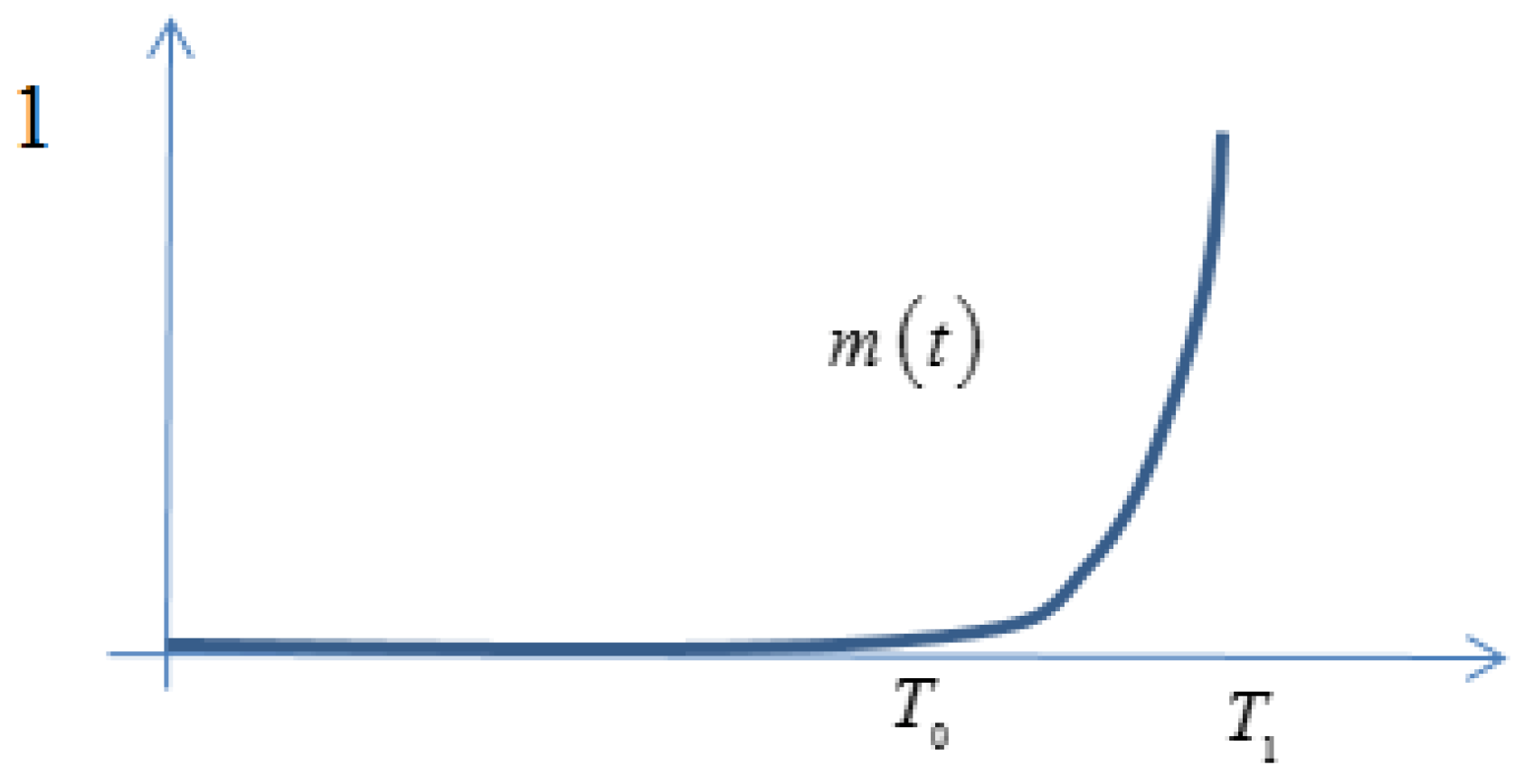
The interpolator (signifying degree of gelling) is given by
ν = h ( C n , C p ) 0 T 1 m ( τ ) p ( x , t ; τ ) d τ
where h ( C n , C p ) is a tabulated function, and m ( τ ) is a weight function defining how the age of the nanomaterials influences gel strength. The (normalized) function m ( τ ) , τ [ 0 , T 1 ] 
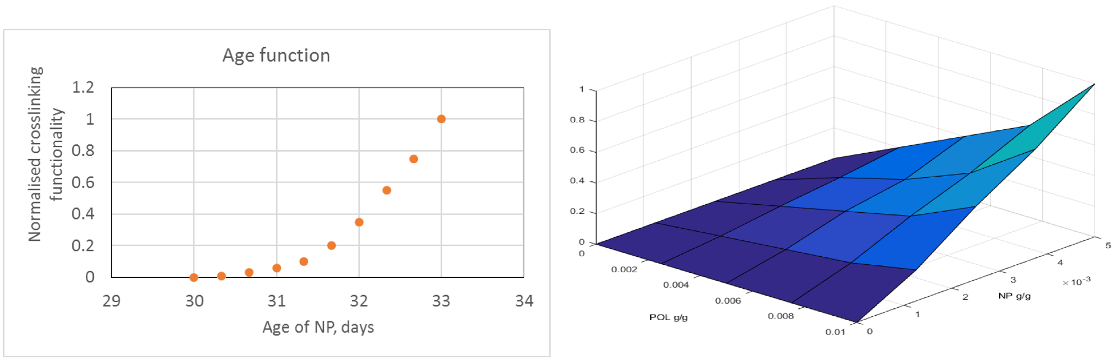
, measures the increase in water viscosity (that is interpolator value) as a function of nanomaterial aging. Typically, m ( τ ) = 0 for τ [ 0 , T 0 ] , m ( τ ) > 0 for τ T 0 , T 1 , and m ( T 1 ) = 1 , as illustrated in Figure A1.
Figure A1. Weight function signifying that gelling is initiated when nanomaterials have age T 0 and when gelling reaches maximal strength at age T 1 .
Energies 12 03758 g0a1
Consequently, the interpolator ν is zero when all nanomaterials have aged less than T 0 . When all nanomaterials have aged more than T 1 , the age profile p is set to δ ( τ T 1 ) , meaning that the integral in Equation (A9) satisfies 0 T 1 m ( τ ) p ( x , t ; τ ) d τ = 1 , giving the maximal value for this integral. We will refer to the integral in Equation (A9) as the age effect (at position x at time t). The function m ( τ ) must be measured or estimated, keeping the nanomaterial and polymer concentrations constant. At this stage, we have assumed m ( τ ) is independent of concentrations, but it would be straightforward to extend this function to depend on more variables. The other factor in Equation (A9), h ( C n , C p ) , would reflect the gel strength as a function of the concentrations when all nanomaterials have the same age and must be measured or estimated from more basic principles. At maximal concentrations, it is assumed that h = 1 , while h ( C n , C p ) = 0 when either of the concentrations are zero (i.e., no gel forms). Thus, when all nanomaterials have aged more than T 1 and when the nanomaterial and polymer concentrations sufficiently high (i.e., when h ( C n , C p ) = 1 ), the interpolator is unity giving maximal value for water viscosity.

Appendix A.4. Numerical Realization, a Summary

It is important to formulate a numerical scheme that is as stable as possible. Consequently, the coupled conservation laws for water saturation, polymer concentrations, and nanomaterial concentrations are solved numerically using (mainly) an implicit scheme. As the model is spatially 1-D, not too many numerical grid blocks are needed, even for a fine spatial resolution. Few grid blocks also allow for using a small maximal time step without forbiddingly long simulation times. Therefore, the inherited numerical diffusion in implicit schemes can be limited by demanding short time steps and using a first-order implicit scheme (backward Euler) is sufficient for obtaining satisfactory precision. Also, the 1-D formulation results in a block structured Jacobi matrix (tri-block diagonal) in the Newton iterations, allowing for a generalization of the well-known explicit solution of linear equations when the coefficient matrix is tri-diagonal. Consequently, the solver for linear equations is non-iterative, very robust, and fast.
Not all terms are treated implicitly. The age effect 0 T 1 m ( τ ) p ( x , t ; τ ) d τ is updated at the end of the time step, meaning that only the factor h ( C n , C p ) in Equation (A9) is treated implicitly. The age distributions p and q are also recalculated at the end of the time step by using “mass conservation” for nanomaterials of the same age and then by adding the time step length to the age of all present nanomaterials. Incidentally, problems were encountered when solving for the “mass conservation” of the variously aged nanomaterials. An explicit scheme for solving for the transport of various aged nanomaterials was rendered unstable, while a fully implicit scheme gave rise to forbiddingly high numerical dispersion. However, by using an explicit upstream and implicit downstream seems to give excellent profiles for the age distributions. A Google search for this explicit upstream, implicit downstream approach actually revealed one single previous paper on this topic [42].
We first describe how the conservation equations are solved numerically and then define how the age profiles are updated and how the age effect is calculated.

Appendix A.5. Conversion Equations

The phase mobilities are defined as
λ i = k r i μ i , i = w , o
First, we eliminate the pressure from the system of equations to obtain the standard Buckley–Leverett formulation. Adding the two equations given by Equation (A1) and using S w + S o = 1 , we obtain x ( u w + u o ) = 0 which means that u T = u w + u o = u T ( t ) , where u T is the total volumetric flux defined by the boundary conditions. From Equation (A2), we then solve for the pressure (-derivative)
P x = u T k λ T
where λ T = λ w + λ o is the total mobility. In particular, Equation (A11) is used for calculating the pressure after a converged time step. Note that the absolute permeability only enters in the model through Equation (A11) (not in the system of equations we solve) when the pressures are calculated for reporting purposes. Indeed, when using rate-controlled boundary conditions and incompressible flow, the pressure is not “an issue” as it is eliminated by Equation (A11) from the set of equations. Also, note that total volumetric flux u T ( t ) in Equation (A11) is given from the input data, not calculated. From Equation (A1) with i = w , we then obtain
ϕ S w t + u T ( t ) f w x = 0
where f w = λ w λ T is the fractional flow of water. The mass conservation equations for nanomaterials and polymers given by Equation (A4) are then expressed as
t C k ϕ ( k ) S w + C a k ( C k ) ( 1 ϕ ( k ) ) ρ r + u T ( t ) x ( C k f w ) = 0 , k = n , p
The three equations given by Equations (A12) and (A13) are coupled and nonlinear and are solved for S w , C n , and C p using Euler’s backward method, with the explicit exceptions referred to earlier.
Given Δ x and Δ t ( Δ t varies in general for different time steps, while Δ x is assumed constant) at time t = t n , we let S w ( i Δ x , t n + Δ t ) S i n + 1 and similarly for the other space and/or time dependent variables. Equation (A12) becomes
E i S i 1 n + 1 , C N M , i 1 n + 1 , C p o l , i 1 n + 1 , S i n + 1 , C NM , i n + 1 , C p o l , i n + 1 =     ϕ S i n + 1 S i n Δ t + u T n + 1 f i n + 1 S i n + 1 , C NM , i n + 1 , C p o l , i n + 1 f i 1 n + 1 S i 1 n + 1 , C NM , i 1 n + 1 , C p o l , i 1 n + 1 Δ x = 0
where we have dropped the w index for water saturation and fractional flow. In simulations, the time step is such that the total rate u T is constant in the corresponding time interval. We have assumed the direction of flow is with increasing spatial index value i and the water fractional flow is as indicated calculated using upstream weighted mobilities. As discussed, the water viscosity and, therefore, the water fractional flow f are not entirely implicitly calculated, as the age-profiles p and the shear-thinning effect are treated explicitly.
The flux term in Equation (A13) is also given by upstream weighting (assuming flow in direction of increasing index i).
F k , i S i 1 n + 1 , C NM , i 1 n + 1 , C p o l , i 1 n + 1 , S i n + 1 , C NM , i n + 1 , C p o l , i n + 1 = u T n + 1 C k , i n + 1 f i n + 1 C k , i 1 n + 1 f i 1 n + 1 Δ x , k = n , p
The time derivative of the capacity term is approximated by
G k , i S i n + 1 , C k , i n + 1 =    ϕ ( k ) C k , i n + 1 S i n + 1 C k , i n S i n Δ t + 1 ϕ ( k ) ρ r C a k C k , i n + 1 C a k C k , i n Δ t U C k , i n + 1 C k , i n , w k , k = n , p
where
U ( x , w ) = 1 if w = 0   &   x 0 , or if w = 1 U ( x , w ) = 0 if w = 0   &   x < 0
Here, w k = 1 if desorption can occur for component k , ( k = n , p ) and w k = 0 if desorption does not occur.
As the model presently allows only water to be injected, we have q T n + 1 = Q w n + 1 A , where Q w n + 1 is the given volumetric injection rate for water in the time interval t n , t n + 1 and where A is the cross-sectional area of the porous medium. Furthermore f 0 n + 1 = 1 , C k , 0 n + 1 = C k , i n j n + 1 , and k = n , p , where C k , i n j n + 1 is the given injection concentration of component k in the time interval t n , t n + 1 , and is constant during a time step. Let n x denote the number of grid blocks. For i = 1 , 2 , , n x , we then have the 3 n x algebraic equations:
E i S i 1 n + 1 , C NM , i 1 n + 1 , C p o l , i 1 n + 1 , S i n + 1 , C NM , i n + 1 , C p o l , i n + 1 = 0 ,
G NM , i S i n + 1 , C NM , i n + 1 + F NM , i S i 1 n + 1 , C NM , i 1 n + 1 , C p o l , i 1 n + 1 , S i n + 1 , C NM , i n + 1 , C p o l , i n + 1 = 0 ,
G pol , i S i n + 1 , C pol , i n + 1 + F pol , i S i 1 n + 1 , C NM , i 1 n + 1 , C p o l , i 1 n + 1 , S i n + 1 , C NM , i n + 1 , C p o l , i n + 1 = 0 ,
for the 3 n x unknowns S i n + 1 , C NM , i n + 1 , C p o l , i n + 1 , i = 1 , 2 , , n x .
This set of nonlinear equations is solved using Newton’s method for systems of equations. The 3 n x × 3 n x Jacobi matrix is sparse, and the block diagonal where the block matrices are generally 6 × 6 matrices. Due to this structure, Gauss elimination does not destroy the sparse structure, and also the number of arithmetic operations in the Gauss-elimination only grows linearly with n x .
We will not write down the explicit formula for the Jacobi matrix as used in the computer code but report that the Newton iteration shows excellent second-order convergence using S i n , C NM , i n , C p o l , i n , i = 1 , 2 , , n x as the initial guess in the iteration, which actually validates the expressions obtained and used for the various partial derivatives needed for forming the Jacobi matrix.
One can also analyze the explicit expression for the matrix to conclude that the Jacobi matrix is always not near singular, and no attempt have been made at this stage for calculating the condition number for the matrix.
It is important that C NM , i n + 1 and C p o l , i n + 1 are scaled in the system of equations. This gives contributions from saturations and concentrations equal footing in the calculation of the residual in each Newton iteration.

Appendix A.6. Updating Age Profiles

At each position and at each time step, the nanomaterials in solution and the adsorbed nanomaterials each have their own age profile p and q. These age profiles are probability distributions on the interval [ 0 , T 1 ] , i.e., p 0 and 0 T 1 p ( x , t ; τ ) d τ = 1 , and likewise for q. No gelling (cross-linking) can occur before nanomaterials reach the minimum gelling age T 0 . Maximally strong gel may form at a given position and time when all the nanomaterials in solution have reached age T 1 (if also h ( C n , C p ) = 1 ) and the water reaches its maximal viscosity; see Equation (A9)).
The numerical representations of p ( x , t ; τ ) and q ( x , t ; τ ) are given as follows: At time t = t n , we let
p ( i Δ x , t n ; τ r ) = p i n , r , i = 1 , 2 , , n x , r = 1 , 2 , , m n ,
where m n is the number of ages at time t n and similarly for q. The age profile resolution τ 1 , τ 2 , , τ m n is dynamical, but the τ resolution is the same for every position at a given time, both for p and q.
At early times in the simulation, the list of ages, τ 1 = t n t n 1 , τ 2 = t n t n 2 , , τ n 1 = t n t 1 , τ n = t n , is defined by the length of the time steps. When the (user-defined) maximum number of ages is obtained, the list of ages is recalculated. The maximal number of ages with τ k < T 0 is a given input value, and the same applies for the maximal numbers of ages for T 0 τ k T 1 . When the maximum number of ages is reached, either ages younger than T 0 or for ages in the interval [ T 0 , T 1 ] , the ages are redistributed evenly and the age fractions p and q corresponding to the new list of ages are recalculated to match the previous representation of p and q. The recalculation of p and q uses linear interpolation for obtaining new values of p i n , k and q i n , k and a renormalization to ensure k = 1 m n p i n , k Δ τ k = 1 and k = 1 m n q i n , k Δ τ k = 1 . When all ages of the nanomaterials in solution are older than T 1 , the age effect entering in Equation (A9), 0 T 1 m ( τ ) p ( x , t ; τ ) d τ is simply set to unity.
Now, assume we have obtained S i n + 1 , C NM , i n + 1 , C p o l , i n + 1 , i = 1 , 2 , , n x at time t = t n + 1 from solving the conservation equations. In addition, we know the age distributions p i n , k and q i n , k at time t = t n .
The flux of nanomaterials having ages in the interval τ k , τ k + 1 is
p ( x , t ; τ ) C n ( x , t ) u w ( x , t ) Δ τ = p ( x , t ; τ ) C n ( x , t ) u T ( t ) f w ( x , t ) Δ τ
To compute the x derivative, we will adopt an explicit upstream, implicit downstream method. That is, we will let
x p ( x , t ; τ ) C n ( x , t ) u T ( t ) f w ( x , t ) Δ τ u T n + 1 Δ x p i n + 1 , k C n , i n + 1 f i n + 1 p i 1 n , k C n , i 1 n f i 1 n Δ τ
Thus,
u T n + 1 p i n + 1 , k C n , i n + 1 f i n + 1 p i 1 n , k C n , i 1 n f i 1 n Δ τ A Δ t
approximates the mass (or molar) of nanomaterials in solution with ages in the interval τ k , τ k + Δ τ flowing out of grid block x i 1 , x i , i = 1 , 2 , , n x during the time step t n , t n + Δ t . Here, A is the cross-sectional area of the model. As previously discussed, any other way of realizing the x derivative in Equation (A23) leads to nonphysical results, either highly unstable (using explicit both up- and downstream) or forbiddingly dispersive (using a full implicit formulation).
Assume first that the mass of nanomaterials flowing out of the grid block is negative. Then, the nanomaterial concentration increases locally, and consequently, no adsorbed nanomaterials will desorb at this position. Therefore, the age profile of the adsorbed nanomaterials q i n , k at time t n will not affect the new age profile p i n + 1 , k , k = 1 , 2 , , m n + 1 of the nanomaterials in solution at time t n + 1 . The mass of nanomaterials with ages in the interval τ k , τ k + Δ τ is
p ( x , t ; τ ) C n ( x , t ) ϕ ( n ) S w ( x , t ) + q ( x , t ; τ ) C a n ( C n ( x , t ) ) ( 1 ϕ ( n ) ) ρ r Δ τ A Δ x
Thus, numerically, the change of mass for these materials during the time step t n , t n + Δ t is
[ ϕ ( n ) p i n + 1 , k C n , i n + 1 S i n + 1 p i n , k C n , i n S i n +                       ρ r ( 1 ϕ ( n ) ) q i n + 1 , k C a n ( C n , i n + 1 ) q i n , k C a n ( C n , i n ) ] Δ τ A Δ x
We can eliminate q i n + 1 , k by noting that the increased mass of adsorbed nanomaterials at this time step is
C a n ( C n , i n + 1 ) C a n ( C n , i n ) ρ r 1 ϕ ( n ) A Δ x
Thus, the increased mass of absorbed nanomaterials (which all come from the nanomaterials in solution) with ages in the interval τ k , τ k + Δ τ is
p i n + 1 , k C a n ( C n , i n + 1 ) C a n ( C n , i n ) ρ r 1 ϕ ( n ) A Δ x .
Writing down mass conservation for absorbed nanomaterials of this age, we find
p i n + 1 , k C a n ( C n , i n + 1 ) C a n ( C n , i n ) ρ r 1 ϕ ( n ) A Δ x + C a n ( C n , i n ) ρ r 1 ϕ ( n ) q i n , k = C a n ( C n , i n + 1 ) ρ r 1 ϕ ( n ) q i n + 1 , k A Δ x
Using Equation (A25), we can then eliminate q i n + 1 , k in Equation (A24).
Thus, formulating the mass conservation for nanomaterials of age τ k , τ k + Δ τ using Equations (A23) and (A24) (having eliminated q i n + 1 , k ), we simply obtain an explicit formula p i n + 1 , k . Then, from Equation (A25), we find the values for q i n + 1 , k .
Assume now that the mass of nanomaterials decreases at a given position during a time step, i.e., that Equation (A23) is positive. Then, if the option for no desorption of nanomaterials is set, the age profile for the adsorbed nanomaterials stays the same (except that all the adsorbed nanomaterials age the amount of the time step) and C a n ( C n , i n + 1 ) C a n ( C n , i n ) = 0 . Thus, Equation (A25) is satisfied, and q i n + 1 , k = q i n , k . The mass conservation for p i n + 1 , k can be solved directly.
If desorption of nanomaterials can occur, then Equation (A25) still applies and p i n + 1 , k and q i n + 1 , k can be found as previously described for the case when Equation (A23) is negative.
We also observe that the procedure for updating the age profiles is done independently for each k.
In Equation (A23) for i = 1 , the age profile for the injected nanomaterials, p 0 n , k , has p 0 n , 1 = 1 and p 0 n , k = 0 for k 2 . That is, all injected nanomaterials have minimum age. Note that it is simple to modify the model to allow for a general user-defined age profile of the injected nanomaterials.
When p i n + 1 , k and q i n + 1 , k have been determined, the ages the distributions represent are of course increased by one time step and the k index is shifted one up. In fact, when the user-defined maximal number of ages is reached, the computer code will always recalculate the representations of the age profiles as previously described, since adding a new age will exceed the maximal number of ages.
Finally, the age profile p i n + 1 , k , k = 1 , 2 , , m n + 1 is used for estimating the integral
T 0 T 1 m ( τ ) p ( x , t ; τ ) d τ
the age effect.
Since m and p generally are represented with values at different nodes, we linearly interpolate p to match the nodes where m is given and calculate the integral using the trapezoidal method. This value for the age effect is then used in the upcoming new time step, where the other parameters defining water viscosity are treated implicitly in this new next time step (except the shear thinning effect).

Appendix A.7. Table-Based Input

A number of the functions needed for the model are table based, allowing for input generality. These functions constitute part of the input for the model and must be measured in the laboratory or estimated from physical principles. All tabulated functions are either functions of one or two variables. Numerical noise may result in function calls outside the given domain, which could lead to ambiguities and possible failure of simulation. For functions of a single variable (defined on an interval), the code will both interpolate and extrapolate linearly. However, the program issues a warning when it has to extrapolate a function outside its given domain, reporting which function and which out-of-domain argument value it extrapolates to.
Two-variable functions are defined on a rectangle a , b × c , d . Two-variable functions are evaluated by successive linear interpolation. Concerning extrapolation outside the domain of definition for an argument ( x , y ) which both has x a , b and y a , b , the error will be fatal and the program stops. In case of membership in only one of the intervals, the code will extrapolate linearly and report a warning.
Also, the various derivatives of table-defined functions are needed for the Jacobi matrix. The derivatives are piecewise constant and are calculated consistently with the linear interpolation of function values. Regarding extrapolation of derivatives, the values of derivatives are simply extended constantly outside their domains, both the ordinary and the partial derivatives.
As mentioned so far, the Newton iterations behave excellently, showing second-order convergence. This indicates that the implemented formulation and evaluation of function values and derivatives of table-based functions is sound and robust.

References

  1. BP. BP Statistical Review of World Energy; Technical Report; BP Energy Economics: London, UK, 2018. [Google Scholar]
  2. OG21. Exploration and Increased Recovery; Technical Report November 2011, OG21—Oil and Gas in the 21st Century—Technology Strategy TTA2 Group; OG21: Lysaker, Norway, 2011. [Google Scholar]
  3. Olje-og Energidepartementet. Økt Utvinning på Norsk Kontinentalsokkel—En Rapport fra Utvinningsutvalget; Technical Report; The Royal Norwegian Ministry of Petroleum and Energy: Oslo, Norway, 2010. [Google Scholar]
  4. Jain, K. Nanobiotechnology-Based Drug Delivery to the Central Nervous System. Neurodegener. Dis. 2007, 4, 287–291. [Google Scholar] [CrossRef]
  5. Perret, G.; Ginet, P.; Tarhan, M.; Baccouche, A.; Lacornerie, T.; Kumemura, M.; Jalabert, L.; Cleri, F.; Lartigau, E.; Kim, B.; et al. Nano systems and devices for applications in biology and nanotechnology. Solid-State Electron. 2016, 115, 66–73. [Google Scholar] [CrossRef]
  6. Polat, R.; Demirboğa, R.; Karagöl, F. The effect of nano-MgO on the setting time, autogenous shrinkage, microstructure and mechanical properties of high performance cement paste and mortar. Constr. Build. Mater. 2017, 156, 208–218. [Google Scholar] [CrossRef]
  7. Mohamadian, N.; Ghorbani, H.; Wood, D.; Hormozi, H.K. Rheological and filtration characteristics of drilling fluids enhanced by nanoparticles with selected additives: An experimental study. Adv. Geo-Energy Res. 2018, 2, 228–236. [Google Scholar] [CrossRef]
  8. Krishnamoorti, R. Extracting the Benefits of Nanotechnology for the Oil Industry. J. Pet. Technol. 2015, 58, 24–26. [Google Scholar] [CrossRef]
  9. Wasan, D.T.; Nikolov, A.D. Spreading of nanofluids on solids. Nature 2003, 423, 156–159. [Google Scholar] [CrossRef]
  10. Esmaeili, A. Applications of nanotechnology in oil and gas industry. AIP Conf. Proc. 2011, 1414, 133–136. [Google Scholar] [CrossRef]
  11. Amanullah, M.; AlArfaj, M.K.; Al-abdullatif, Z.A. Preliminary Test Results of Nano-based Drilling Fluids for Oil and Gas Field Application. In Proceedings of the SPE/IADC Drilling Conference and Exhibition, Amsterdam, The Netherlands, 1–3 March 2011. [Google Scholar] [CrossRef]
  12. Van Zanten, R.; Ezzat, D. Surfactant Nanotechnology Offers New Method for Removing Oil-Based Mud Residue to Achieve Fast, Effective Wellbore Cleaning and Remediation. In Proceedings of the SPE International Symposium and Exhibition on Formation Damage Control, Lafayette, LA, USA, 10–12 February 2010. [Google Scholar] [CrossRef]
  13. Maserati, G.; Daturi, E.; Del Gaudio, L.; Belloni, A.; Bolzoni, S.; Lazzari, W.; Leo, G. Nano-emulsions as Cement Spacer Improve the Cleaning of Casing Bore During Cementing Operations. In Proceedings of the SPE Annual Technical Conference and Exhibition, Florence, Italy, 19–22 September 2010. [Google Scholar] [CrossRef]
  14. Hurnaus, T.; Plank, J. Crosslinking of Guar and HPG Based Fracturing Fluids Using ZrO2 Nanoparticles. In Proceedings of the SPE International Symposium on Oilfield Chemistry, The Woodlands, TX, USA, 13–15 April 2015. [Google Scholar] [CrossRef]
  15. Murugesan, S.; Monteiro, O.R.; Khabashesku, V.N. Extending the Lifetime of Oil and Gas Equipment with Corrosion and Erosion-Resistant Ni-B-Nanodiamond Metal-Matrix-Nanocomposite Coatings. In Proceedings of the Offshore Technology Conference, Houston, TX, USA, 2–5 May 2016. [Google Scholar] [CrossRef]
  16. Jauhari, S.; Parekh, K.; Upadhyay, R. Corrosion Inhibition of Mild Steel in Acidic Media Using a Nanomagnetic Fluid as a Novel Corrosion Inhibitor. In Proceedings of the Corrosion 2011, Houston, TX, USA, 13–17 March 2011. [Google Scholar]
  17. Huang, T.; Crews, J.B.; Willingham, J.R. Nanoparticles for Formation Fines Fixation and Improving Performance of Surfactant Structure Fluids. In Proceedings of the International Petroleum Technology Conference, Kuala Lumpur, Malaysia, 3–5 December 2008. [Google Scholar] [CrossRef]
  18. Huang, T.T.; Clark, D.E. Enhancing Oil Recovery with Specialized Nanoparticles by Controlling Formation-Fines Migration at Their Sources in Waterflooding Reservoirs. SPE J. 2015, 20, 743–746. [Google Scholar] [CrossRef]
  19. Belcher, C.K.; Seth, K.; Hollier, R.; Paternostro, B.P. Maximizing Production Life With the Use of Nanotechnology to Prevent Fines Migration. In Proceedings of the International Oil and Gas Conference and Exhibition in China, Beijing, China, 8–10 June 2010. [Google Scholar] [CrossRef]
  20. Habibi, A.; Pourafshari, P.; Ahmadi, M.; Ayatollahi, S. Reduction of Fine Migration by Nanofluids Injection, An Experimental Study. In Proceedings of the SPE European Formation Damage Conference, Noordwijk, The Netherlands, 7–10 June 2011. [Google Scholar] [CrossRef]
  21. Ogolo, N.C.; Olafuyi, O.A.; Onyekonwu, M. Effect of Nanoparticles on Migrating Fines in Formations. In Proceedings of the SPE International Oilfield Nanotechnology Conference and Exhibition, Noordwijk, The Netherlands, 12–14 June 2012. [Google Scholar] [CrossRef]
  22. Ahmadi, M.; Habibi, A.; Pourafshary, P.; Ayatollahi, S. Zeta-Potential Investigation and Experimental Study of Nanoparticles Deposited on Rock Surface to Reduce Fines Migration. SPE J. 2013, 18, 534–544. [Google Scholar] [CrossRef]
  23. Li, S.; Hendraningrat, L.; Torsaeter, O. Improved Oil Recovery by Hydrophilic Silica Nanoparticles Suspension: 2-Phase Flow Experimental Studies. In Proceedings of the International Petroleum Technology Conference, Beijing, China, 26–28 March 2013. [Google Scholar] [CrossRef]
  24. Hendraningrat, L.; Torsæter, O. Effects of the Initial Rock Wettability on Silica-Based Nanofluid-Enhanced Oil Recovery Processes at Reservoir Temperatures. Energy Fuels 2014, 28, 6228–6241. [Google Scholar] [CrossRef]
  25. Yu, H.; Kotsmar, C.; Yoon, K.Y.; Ingram, D.R.; Johnston, K.P.; Bryant, S.L.; Huh, C. Transport and Retention of Aqueous Dispersions of Paramagnetic Nanoparticles in Reservoir Rocks. In Proceedings of the SPE Improved Oil Recovery Symposium, Tulsa, OK, USA, 24–28 April 2010. [Google Scholar] [CrossRef]
  26. Zargartalebi, M.; Kharrat, R.; Barati, N. Enhancement of surfactant flooding performance by the use of silica nanoparticles. Fuel 2015, 143, 21–27. [Google Scholar] [CrossRef]
  27. Manan, M.A.; Farad, S.; Piroozian, A.; Esmail, M.J.A. Effects of Nanoparticle Types on Carbon Dioxide Foam Flooding in Enhanced Oil Recovery. Pet. Sci. Technol. 2015, 33, 1286–1294. [Google Scholar] [CrossRef]
  28. Fletcher, A.; Davis, J. How EOR Can be Transformed by Nanotechnology. In Proceedings of the SPE Improved Oil Recovery Symposium, Tulsa, OK, USA, 24–28 April 2010; pp. 24–28. [Google Scholar] [CrossRef]
  29. Ayatollahi, S.; Zerafat, M. Nanotechnology-Assisted EOR Techniques: New Solutions to Old Challenges. In Proceedings of the SPE International Oilfield Nanotechnology Conference, Noordwijk, The Netherlands, 12–14 June 2012; pp. 1–15. [Google Scholar] [CrossRef]
  30. Cocuzza, M.; Pirri, F.; Rocca, V.; Verga, F.; Torino, P. Is the Oil Industry Ready for Nanotechnologies? In Proceedings of the Offshore Mediterranean Conference and Exhibition, Ravenna, Italy, 23–25 March 2011; pp. 1–17. [Google Scholar]
  31. Mo, D.; Jia, B.; Yu, J.; Liu, N.; Lee, R. Study Nanoparticle-stabilized CO2 Foam for Oil Recovery at Different Pressure, Temperature, and Rock Samples. In Proceedings of the SPE Improved Oil Recovery Symposium, Tulsa, OK, USA, 12–16 April 2014. [Google Scholar] [CrossRef]
  32. Jia, B.; Tsau, J.S.; Barati, R. A review of the current progress of CO2 injection EOR and carbon storage in shale oil reservoirs. Fuel 2019, 236, 404–427. [Google Scholar] [CrossRef]
  33. Cordova, M.; Cheng, M.; Trejo, J.; Johnson, S.J.; Willhite, G.P.; Liang, J.T.; Berkland, C. Delayed HPAM gelation via transient sequestration of chromium in polyelectrolyte complex nanoparticles. Macromolecules 2008, 41, 4398–4404. [Google Scholar] [CrossRef]
  34. Johnson, S.J.; Trejo, J.; Veisi, M.; Willhite, G.P.; Liang, J.T.; Berkland, C. Effects of divalent cations, seawater and formation brine on positively charged polyethylenimine/dextran sulfate/Cr(III) polyelectrolyte complexes and HPAM/Cr(III) gelation. J. Appl. Polym. Sci. 2010, 115, 1008–1014. [Google Scholar] [CrossRef]
  35. Li, H.; Wang, K.; Han, X.; Zheng, J. Research on heterogeneous compound flooding system based on dispersed particle gel. Adv. Geo-Energy Res. 2019, 3, 156–164. [Google Scholar] [CrossRef] [Green Version]
  36. Sydansk, R.; Southwell, G. More than 12 Years of Experience with a Successful Conformance-Control Polymer Gel Technology. In Proceedings of the SPE/AAPG Western Regional Meeting, Long Beach, CA, USA, 19–23 June 2000. [Google Scholar] [CrossRef]
  37. Männle, F.; Simon, C.; Beylich, J.; Redford, K. Polybranched, Organic/Inorganic Hybrid Polymer and Method for Its Manufacture. 2011. Available online: https://patents.google.com/patent/EP1740643B1/en (accessed on 16 September 2019).
  38. Najafiazar, B.; Yang, J.; Simon, C.R.; Karimov, F.; Torsæter, O.; Holt, T. Transport Properties of Functionalised Silica Nanoparticles in Porous Media. In Proceedings of the SPE Bergen One Day Seminar, Bergen, Norway, 20 April 2016. [Google Scholar] [CrossRef]
  39. Neyertz, S.; Brachet, P.; Brown, D.; Männle, F. The structure of amino-functionalized polyhedral oligomeric silsesquioxanes (POSS) studied by molecular dynamics simulations. Comput. Mater. Sci. 2012, 62, 258–265. [Google Scholar] [CrossRef]
  40. Neyertz, S.; Gopalan, P.; Brachet, P.; Kristiansen, A.; Männle, F.; Brown, D. Oxygen Transport in Amino-Functionalized Polyhedral Oligomeric Silsesquioxanes (POSS). Soft Mater. 2013, 12, 113–123. [Google Scholar] [CrossRef]
  41. Lötsch, T.; Muller, T.; Pusch, G. The Effect of Inaccessible Pore Volume on Polymer Coreflood Experiments. In Proceedings of the SPE Oilfield and Geothermal Chemistry Symposium, Phoenix, AZ, USA, 9–11 April 1985. [Google Scholar] [CrossRef]
  42. Flåtten, T.; Huseby, O.; Sagen, J. On the implicit downwind scheme for scalar convection. Int. J. Pure Appl. Math. 2008, 49, 443–450. [Google Scholar]
  43. Najafiazar, B.; Torsæter, O.; Holt, T. Transport Properties of Nanoparticles in Sandstones. In Proceedings of the 1st International Conference on Unconventional Resources (ICOUR-2016), Islamabad, Pakistan, 30–31 May 2016; p. 10. [Google Scholar]
  44. Schlumberger. Eclipse Industry-Reference Reservoir Simulator, Technical Description; Technical Report; Schlumberger: Houston, TX, USA, 2015. [Google Scholar]
  45. Dake, L.P. Fundamentals of Reservoir Engineering; Elsevier: Amsterdam, The Netherlands, 1978; p. 443. [Google Scholar]
  46. Brooks, R.H.; Corey, A.T. Hydraulic Properties of Porous Media. Hydrol. Pap. 1964, 3, 1–27. [Google Scholar]
  47. Todd, M.; Longstaff, W. The Development, Testing, and Application of a Numerical Simulator for Predicting Miscible Flood Performance. J. Pet. Technol. 1972, 24, 874–882. [Google Scholar] [CrossRef]
Figure 1. Principle of delayed gelation [38]. Nanomaterials with (a) active cross-linking functionality, (b) blocked cross-linking functionality, and (c) partially blocked cross-linking functionality by undergoing slow hydrolysis.
Energies 12 03758 g001
Figure 2. System with delayed gelation based on Texas A&M technology [33] (adapted from a presentation by prof. Jenn-Tai Liang at an internal project meeting).
Energies 12 03758 g002
Figure 3. Schematic of the setup of the core flooding experiments.
Energies 12 03758 g003
Figure 4. Pore size distribution for Bentheimer sandstone.
Energies 12 03758 g004
Figure 5. Polymer/PEC solutions aged at 80 °C. (Upper left) Series 17 samples. (Upper right) Series 18 samples. (Lower left) Series 19 samples. (Lower right) Series 20 samples.
Energies 12 03758 g005
Figure 6. Aging of solutions in Series 23 collected during injection of nanomaterial/polymer solution in a core at 80 °C: Samples collected early (left) and collected at the end of the injection (right).
Energies 12 03758 g006
Figure 7. (a) Viscosity as a function of shear rate and polymer concentration for unreacted Alcomer 24 UK. (b) Reaction model for Alcomer 24 UK.
Energies 12 03758 g007
Figure 8. Comparison of nanomaterial/polymer injection phases.
Energies 12 03758 g008
Figure 9. Concentration of nanoparticles as a function of injected solution: Sensitivity simulations varying number of grid blocks in the model.
Energies 12 03758 g009
Figure 10. Comparison of normalized nanomaterial concentration at the outlet of the core from the experiment and simulation of Experiment 1 (Bentheimer): The normalized nanomaterial response is plotted as function of injected pore volume (PV).
Energies 12 03758 g010
Figure 11. Comparison of normalized polymer concentration at the outlet of the core from the experiment and simulation of Experiment 2 (Bentheimer): Conductivity measurements from the experiment and differential pressure over the core are also plotted.
Energies 12 03758 g011
Figure 12. Comparison of the experiment and simulation of co-injection of nanomaterials and polymers (Experiment 3 with Bentheimer): The nanomaterial response during the first injection slug in the experiment is assumed to be wrong. Conductivity measurements from the experiment and differential pressure over the core are also plotted.
Energies 12 03758 g012
Figure 13. Comparison of polymer response between Schlumberger ECLIPSE and the developed simulator.
Energies 12 03758 g013
Figure 14. Outline of the large-scale model.
Energies 12 03758 g014
Figure 15. (a) Age function for nanomaterials: T0 is at 30 days, and full cross-linking effect is reached at 33 days. (b) h-function (see Equation (A9)): two parameter function of polymer and nanomaterial concentrations.
Energies 12 03758 g015
Figure 16. Differential pressure response for the large-scale gelling simulation with (a) injection of 0.5 PV polymer and nanomaterial slug and (b) injection of 0.25 PV polymer and nanomaterial slug, both followed by SSW injection.
Energies 12 03758 g016
Table 1. Polymers used in the experiments.
NameProducerMW (MDa)Concentration (wt.%)
Alcoflood 254 SBASF0.50.5, 1.0 and 2.0
Alcomer 24 UKBASF60.25, 0.5, 1.0 and 2.0
Flopaam 5115 VHMSNF Floerger12–150.5, 1.0 and 2.0
Table 2. Composition of synthetic seawater (SSW).
SaltConcentration (g/L)
NaCl23.612
CaCl2·2H2O1.911
MgCl2·2H2O9.149
KCl0.746
Na2SO43.407
Table 3. Composition of polymer/polyelectrolyte complex (PEC) sample series with the concentrations in weight%.
Sample C Polymer (wt.%) C HOS (wt.%) C PVS (wt.%) C pol / C HOS C HOS / C PVS
Series 171.0020.3800.0532.647.16
Series 181.0040.3810.1362.642.80
Series 190.9310.3820.2732.641.29
Series 201.0000.436-2.30-
Table 4. Minimum concentration for gel formation for the different polymers with Cr3+ as the cross-linker.
NameConcentration (wt.%)Will Gel at (wt.%)
Alcoflood 254 S0.5, 1.0, 2.02
Alcomer 24 UK0.25, 0.5, 1.0, 2.0>0.25
Flopaam 5115 VHM0.5, 1.0, 2.0≥0.5
Table 5. Porosities, initial and final permeabilities, and residual resistance factors for various aging times.
Exp. No.Porosity (Fraction)Aging Time (Fays)Abs. Perm. (mD)Final Perm. (mD)RRF
10.221726533068.7
20.2212325805.2493
30.2216627060.83230
4NM *Injectivity test2571--
50.2245327100.002158,000
* Not measured.
Table 6. Basic rock parameters and additives used in the experiments in earlier work [38].
Exp. No.RockAdditive
1BentheimerNanomaterials
2BentheimerPolymer
3BentheimerNanomaterials & Polymer
4BereaNanomaterials
5BereaPolymer
5BereaNanomaterials & Polymer
Table 7. Inaccessible pore volumn (IPV) and retention of nanomaterials during Experiment 1.
QuantityUnitStage 1Stage 2Stage 3Stage 4
IPV(PV)-−0.034-−0.02
Retention(mg)4.32.55.84.7
Retention(mg/g rock)0.0090.0050.0130.010
Retention(mg/PV inj)1.89-0.96-
Retention(% of inj NM)3.62.01.81.5
Table 8. IPV, adsorption, and mechanical entrapment of polymer during Experiment 2.
QuantityUnitStage 1Stage 2Stage 3Stage 4
IPV(PV)-0.07-0.13
Mech. entrapment(mg)3.33.31010
Mech. entrapment(mg/g rock)0.0070.0070.0220.022
Mech. entrapment(mg/PV inj)0.74-1.8-
Mech. entrapment(% of inj pol.)1.31.33.32.3
Adsorption(mg)4.8from difference in response curves of stages 1 and 3
Adsorption(mg/g rock)0.010
Table 9. IPV and retention of nanomaterials during Experiment 3.
QuantityUnitStage 1Stage 2Stage 3Stage 4
IPV(PV)-−0.16-−0.08
Retention(mg)153125132114
Retention(mg/g rock)0.350.280.300.26
Retention(mg/PV inj)0.47-0.02-
Retention(% of inj NM)23190.877.9
Table 10. IPV, adsorption, and mechanical entrapment of polymer during Experiment 3.
QuantityUnitStage 1Stage 2Stage 3Stage 4
IPV(PV)-0.07-0.13
Mech. entrapment(mg)2.52.56.886.88
Mech. entrapment(mg/g rock)0.00570.00570.0160.016
Mech. entrapment(mg/PV inj)0.39-0.58-
Mech. entrapment(% of inj pol.)1.51.52.241.90
Adsorption(mg)2.2from difference in response curves of stages 1 and 3
Adsorption(mg/g rock)0.005

