A Review on Communication Standards and Charging Topologies of V2G and V2H Operation Strategies


Abstract

1. Introduction
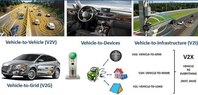
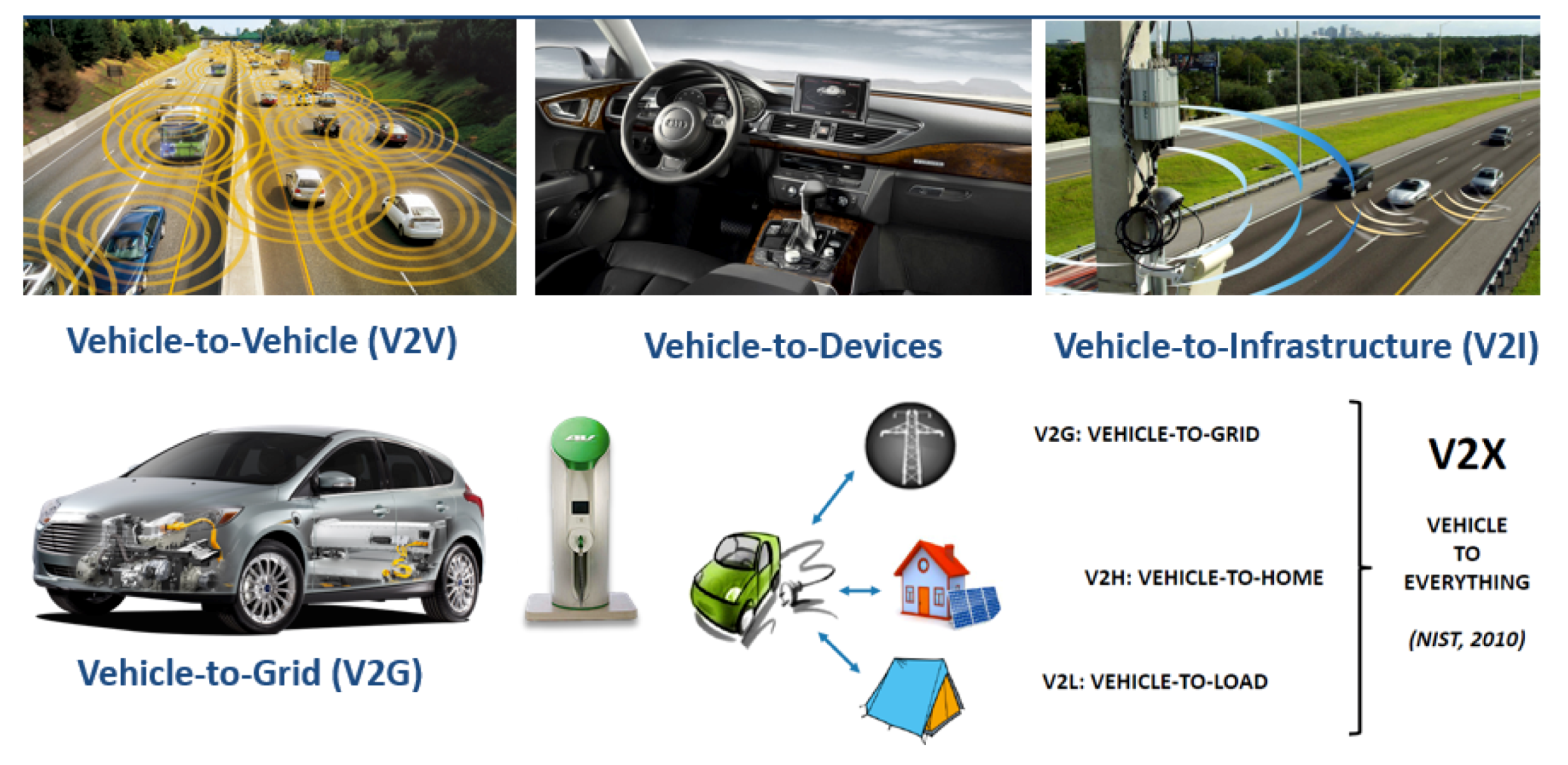
2. Vehicle to X (V2X)
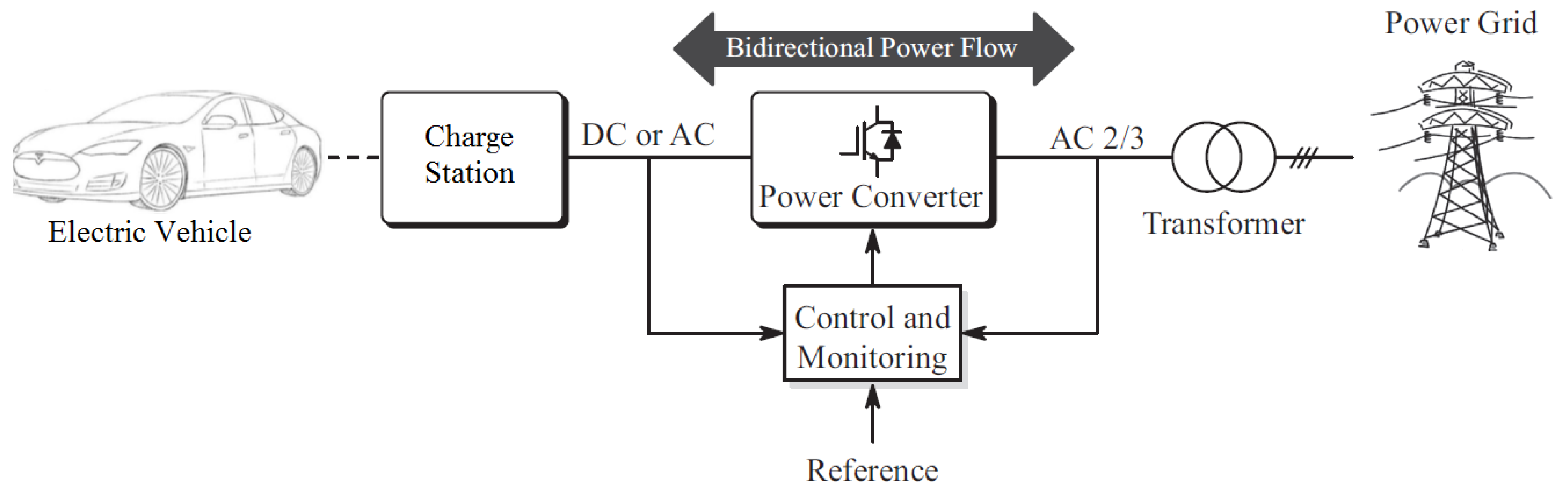
2.1. Vehicle to Grid (V2G)
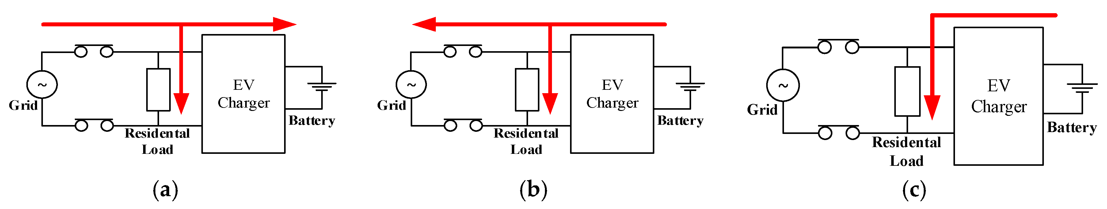
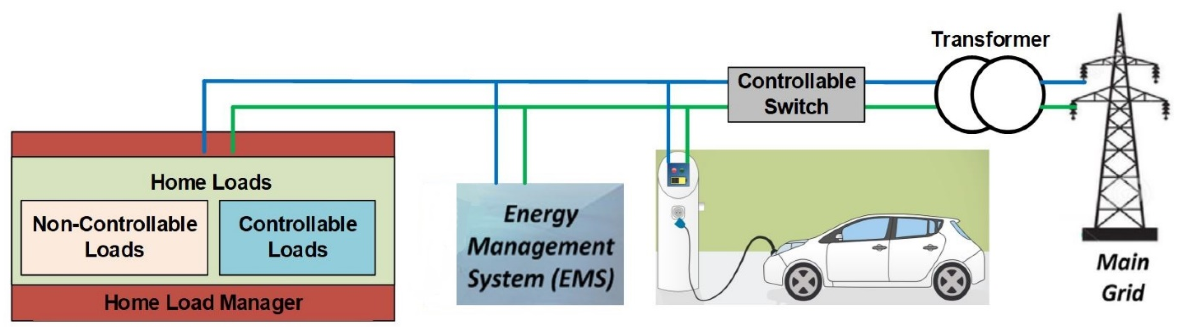
2.2. Vehicle to Home (V2H)
3. Charging Systems of the Batteries of Electrical Vehicles
3.1. Various Converter Topologies Used in V2G and V2H Technologies
3.1.1. Isolated and Non-Isolated Converters
3.1.2. Bi-Directional Half-Bridge and Full-Bridge Controlled Converter
3.1.3. Bi-Directional Buck–Boost Isolated Converter
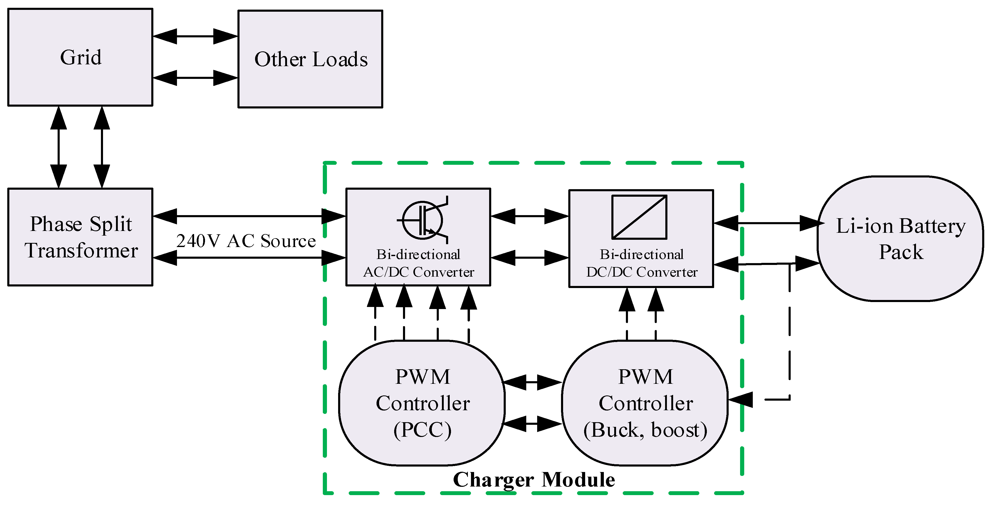
3.1.4. Non-Isolated Charging Topology with PWM and Bi-Directional Buck–Boost DC/DC Converter
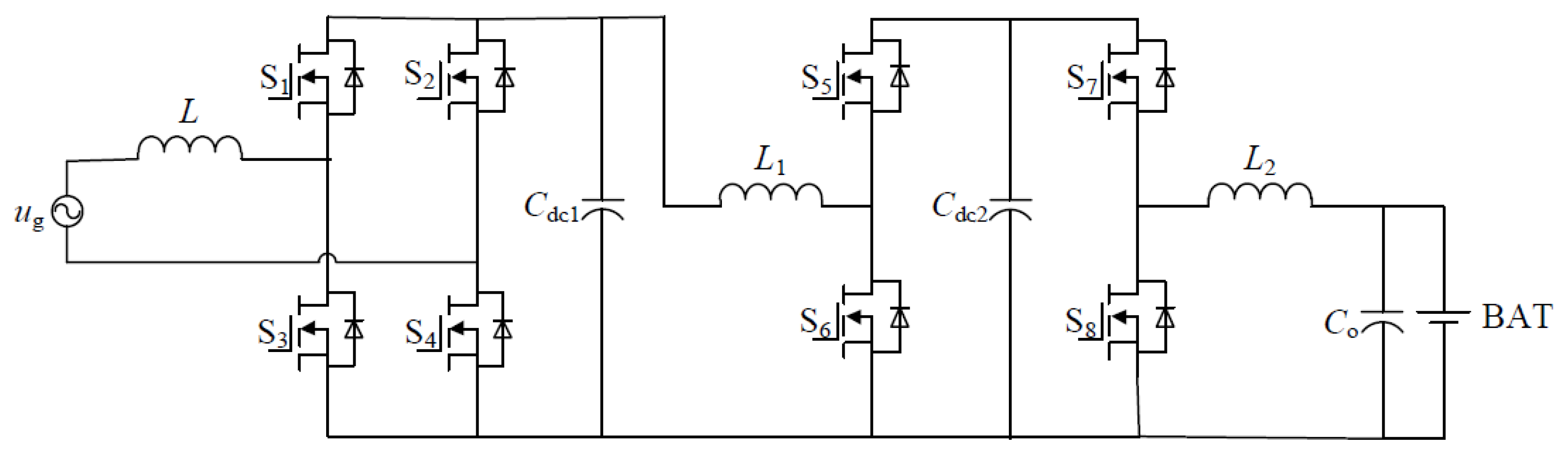
3.1.5. The Non-Isolated Charging Topology with PWM and Bi-Directional Cascade DC/DC Buck–Boost Converter
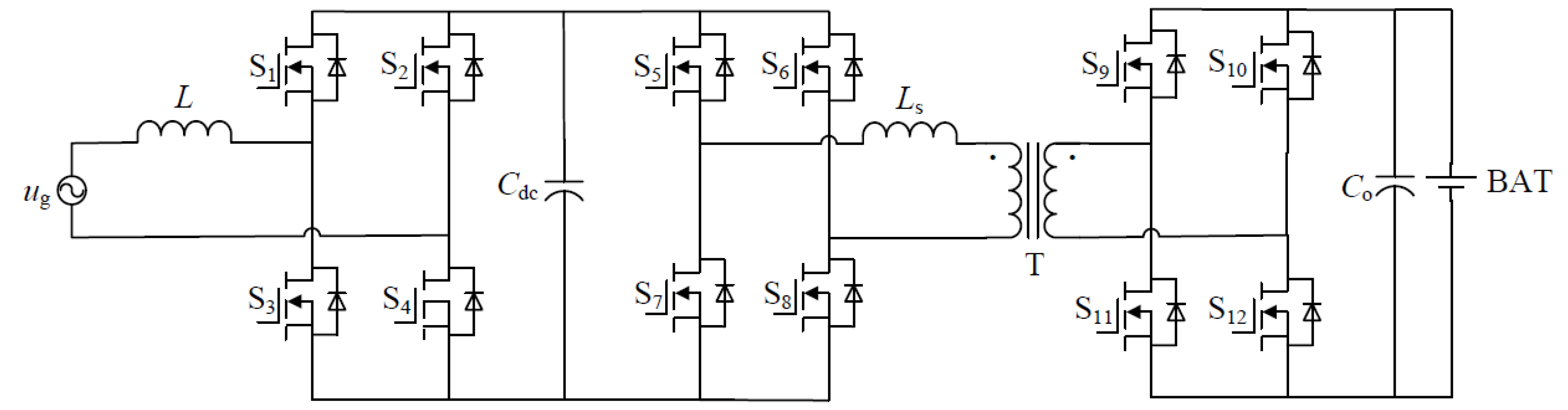
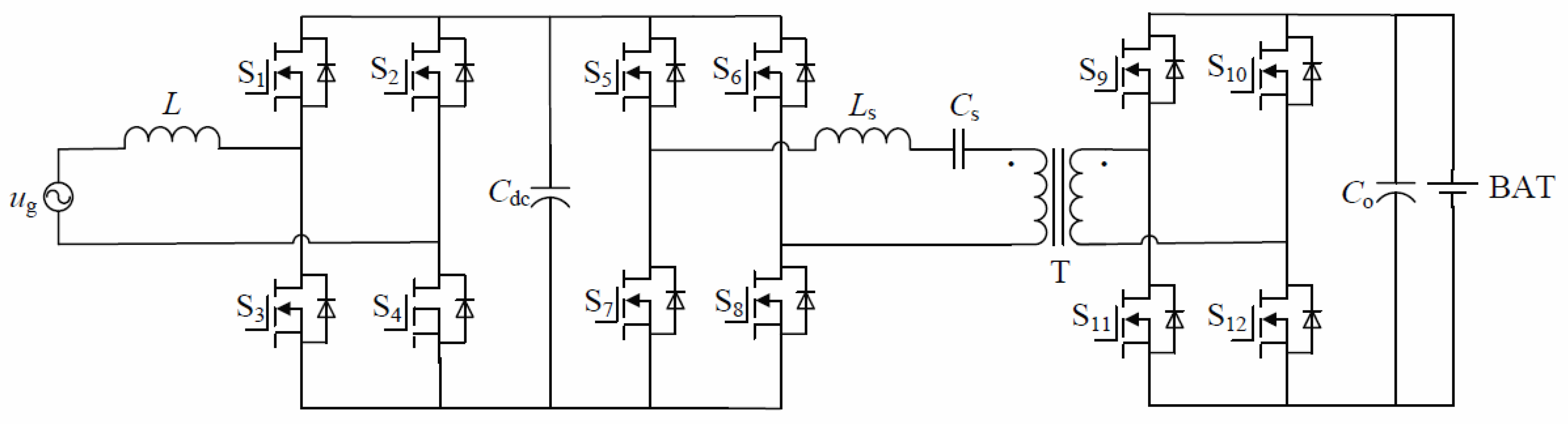
3.1.6. The Two-Stage Topology with PWM Convertor—Active Double Bridge and Series Resonance Convertor
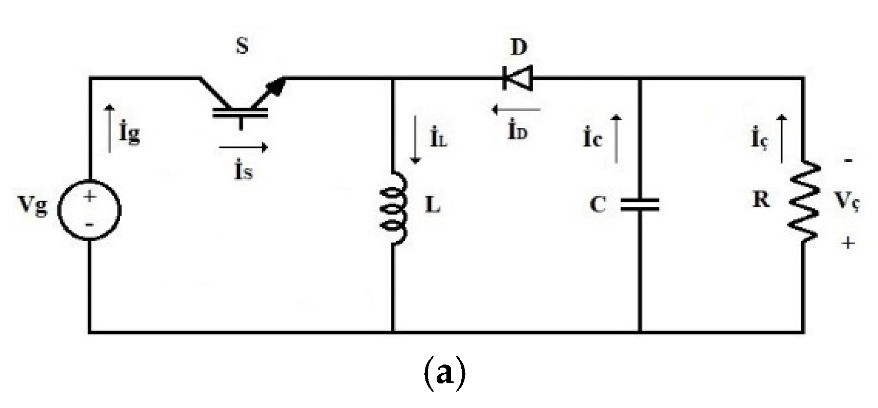
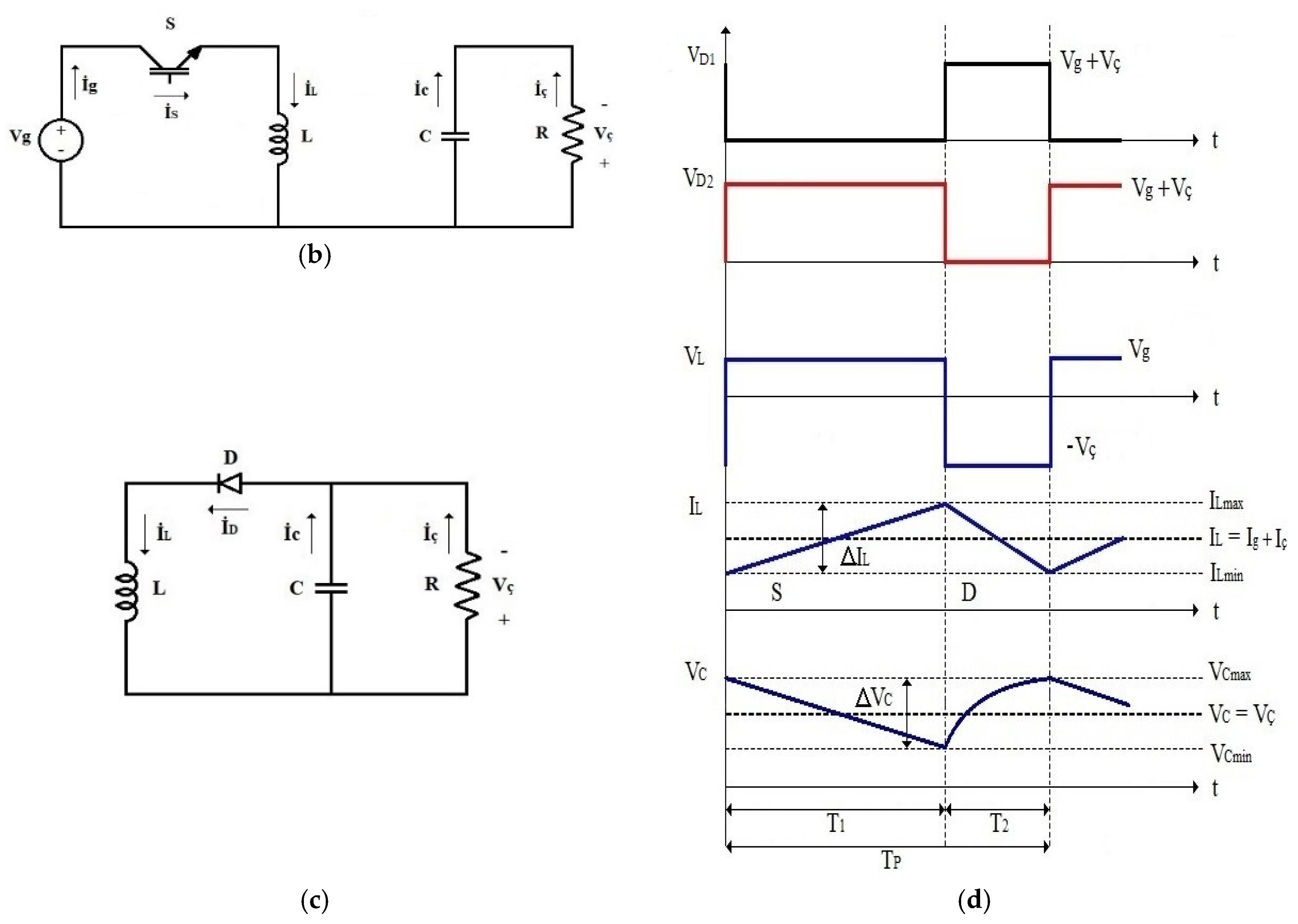
3.1.7. Buck–Boost DC/DC Convertors
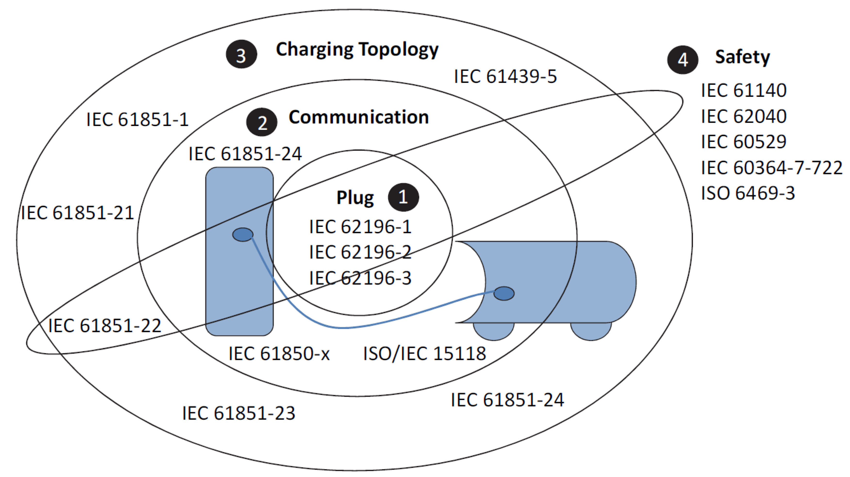
4. Communication Standards in Electrical Vehicles
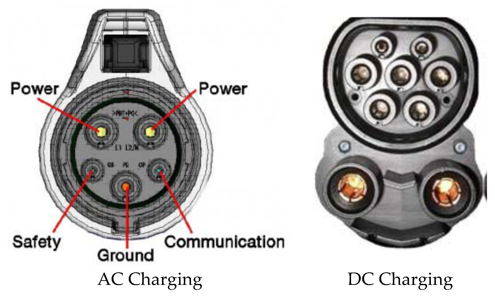
- IEC 62196-1: Plugs, socket-outlets, vehicle couplers and vehicle inlets—conductive charging of electric vehicles, charging of electric vehicles up to 250 A AC and 400 A DC.
- IEC 62196-2: Plugs, socket-outlets, vehicle connectors and vehicle inlets—conductive charging of electrical vehicles, dimensional compatibility, and interchangeability requirements for AC pin and contact-tube accessories.
- IEC 62196-3: Plugs, socket-outlets, and vehicle couplers—conductive charging of electric vehicles, dimensional interchangeability requirements for pin, and contact-tube coupler with rated operating voltage up to 1000 V DC and rated current up to 400 A for dedicated DC charging.
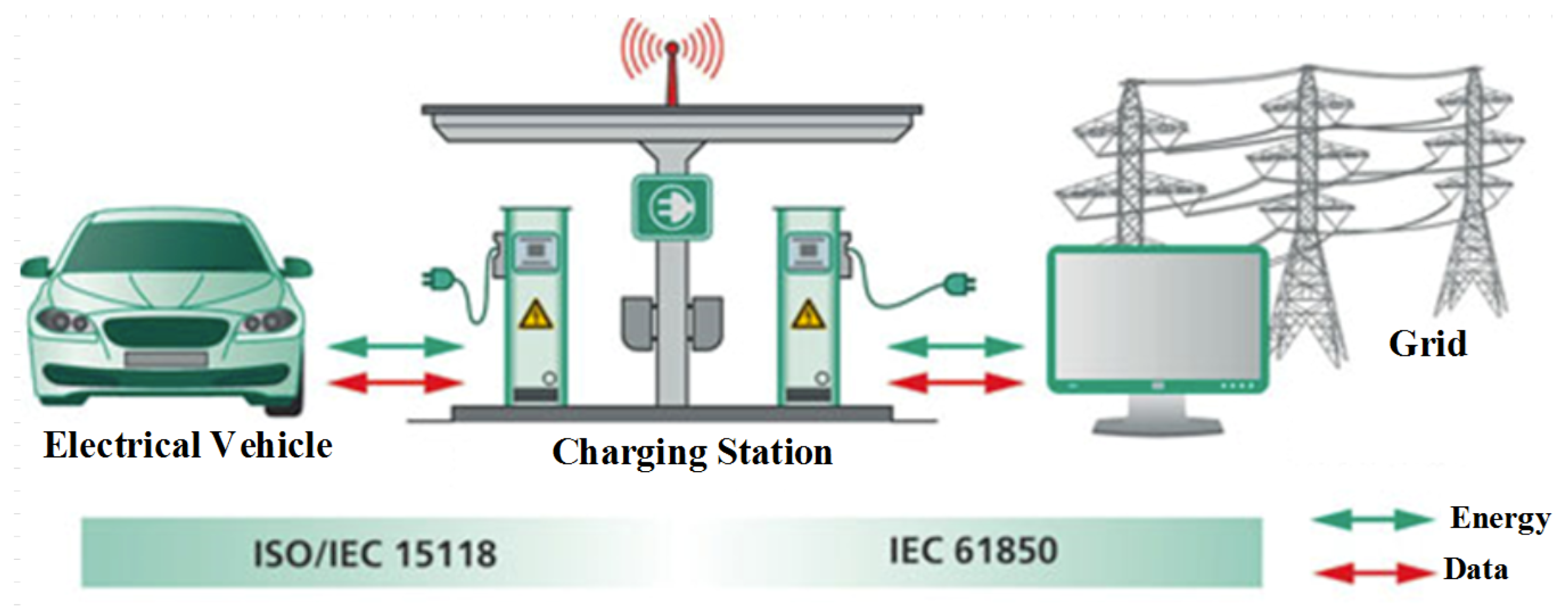
- IEC 61850-x: Communication networks and systems in substations.
- ISO/IEC 15118: Vehicle-to-grid communication interface.
- IEC 61439-5: Low-voltage switchgear and control gear assemblies, and assemblies for power distribution in public networks.
- IEC 61851-1: Electrical vehicle conductive charging system—general requirements.
- IEC 61851-21: Electrical vehicle conductive charging system—electric vehicle requirements for conductive connection to an AC/DC supply.
- IEC 61851-22: Electrical vehicle conductive charging system—AC electric vehicle charging station.
- IEC 61851-23: Electrical vehicle conductive charging system—DC electric vehicle charging station.
- IEC 61851-24: Electrical vehicle conductive charging system—control communication protocol between off-board DC charger and electrical vehicles.
- IEC 61140: Protection against electric shock—common aspects for installation and equipment
- IEC 62040: Uninterruptible power systems (UPS).
- IEC 60529: Degrees of protection provided by enclosures (IP code).
- IEC 60364-7-722: Low voltage electrical installations, requirements for special installations, or locations—supply of electric vehicle.
- ISO 6469-3: Electrically propelled road vehicles, safety specification, and protection of persons against electric shock.
5. Discussion
- V2G and V2H technology ensures that the reactive power is compensated by providing active power or renewable energy sources in the existing grid.
- The advantages of V2G and V2H technology are not only possible for the grid, but also for the owners of electrical vehicles. These systems provide vehicle owners with continuous power support at home or at work.
- Increasing the capacities of the existing energy sources or preparing new energy sources necessitates high costs; therefore, it is less costly to have support from V2G or V2H technologies in periods when the demands are high.
- These technologies increase the energy quality, reliability, and sustainability by reducing frequency regulation and harmonic distortion.
- The technologies are compatible with micro grid and smart grid applications.
- Electrical vehicles provide more stable, safer, and more continuous energy backup or emergency energy support compared with solar wind and other renewable energy sources, which depend on charging.
- While electrical vehicle owners charge their vehicles at low-cost rates at night, they sell energy to the grid during peak hours when energy is expensive within the day, and, thus, obtain financial gains.
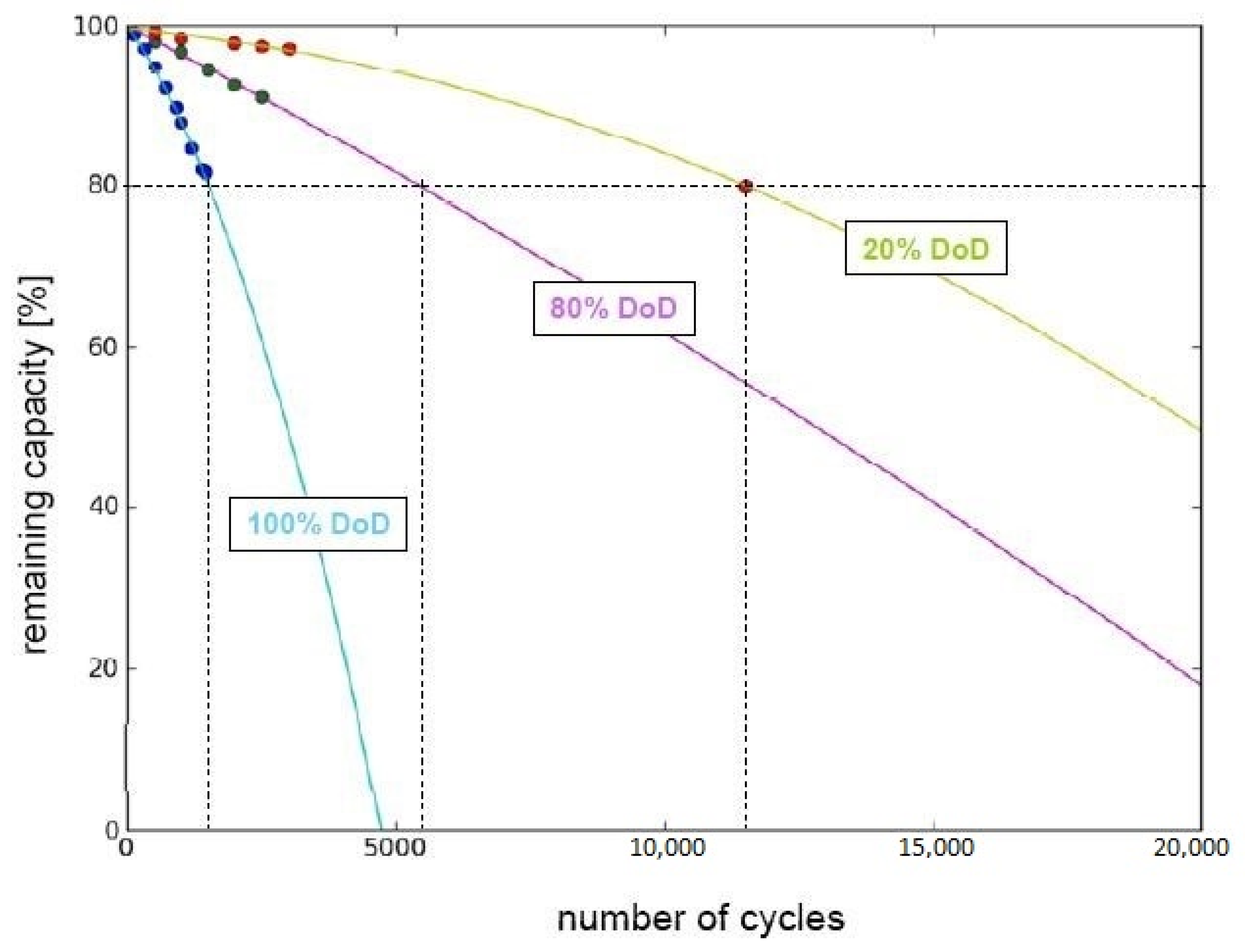
- The life cycle of the batteries will shorten as the charge–discharge process will increase the internal resistance considerably. This negative situation is considered as the disadvantage of these technologies.
- As the fast charging method also shortens the life cycle of batteries, the use of such technologies is not recommended because they cause the breakdown of batteries.
- Purchase of electric vehicles that have V2G or V2H technologies requires high initial costs.
- Coordination and standardization with the grid operators are difficult at initial steps.
- The battery management system can be formed by using optimization and control algorithms to extend the service life of the battery.
- Software and hardware may be developed to measure battery health status to estimate the service life of batteries. In this way, the owner of the battery can be informed before the battery life ends, and thus measures can be taken in terms of contributing to the continuity of the energy.
- As cyber-attacks are becoming increasingly complex, providing necessary measures to deal with current cyber threats will not provide adequate protection. The power system may also become vulnerable to new attacks in the future. For this reason, it is necessary that the basic components of the power system are defined and protected as a whole.
- Wired or wireless communication methods are employed to ensure the security between the energy systems, grids, electric vehicles, and charging station, which are among the critical infrastructures. For this reason, a possible cyber-attack to these critical communication methods may damage the whole system. Necessary preventions must be taken in this respect.
- All batteries lose their capacity over time. Therefore, the amount of energy to be transferred to the grid and the energy to be sold to the grid will decrease with time.
6. Outcomes
- The world’s concern for the environment is on the rise, as traditionally-used non-renewable fuels are harmful and expensive. In order to ensure green transportation technologies, the concept of electric vehicles (EV) has come into the limelight. EVs run on electricity, posing no threats to the environment. They can also be developed on the basis of existing electricity infrastructures, making them less costly. Their additional advantage is that they can store electrical energy and can act as a source when not in use. This feature of EVs has ushered the dawn of V2X technologies.
- V2X is a general term where X is a variable representing either grid (G), home (H), device (D), building (B), or vehicle (V). These are technologies wherein electric energy is supplied from vehicles to the grid, a home, a device, a building, or to another vehicle.
- Vehicle to grid (V2G) technology is a bidirectional energy transfer between a vehicle and the electricity grid. The energy transfer also includes necessary AC/DC or DC/AC conversion, along with magnitude changing. The vehicle charges itself from the grid when the electricity demand is low, or when the electricity prices are less. On the other hand, the vehicle discharges or supplies energy to the grid during the peak demand hours when the electricity prices are high. Thus, the vehicle owner obtains a financial profit through this technology.
- Vehicle to home (V2H) technology is similar to the V2G technology, except that the energy transfer is between a home and the vehicle. If a vehicle supplies a house with energy during the peak hours, the demand on the grid reduces, making the electricity distribution smoother. Again, the vehicle can get charged from the off-peak hours.
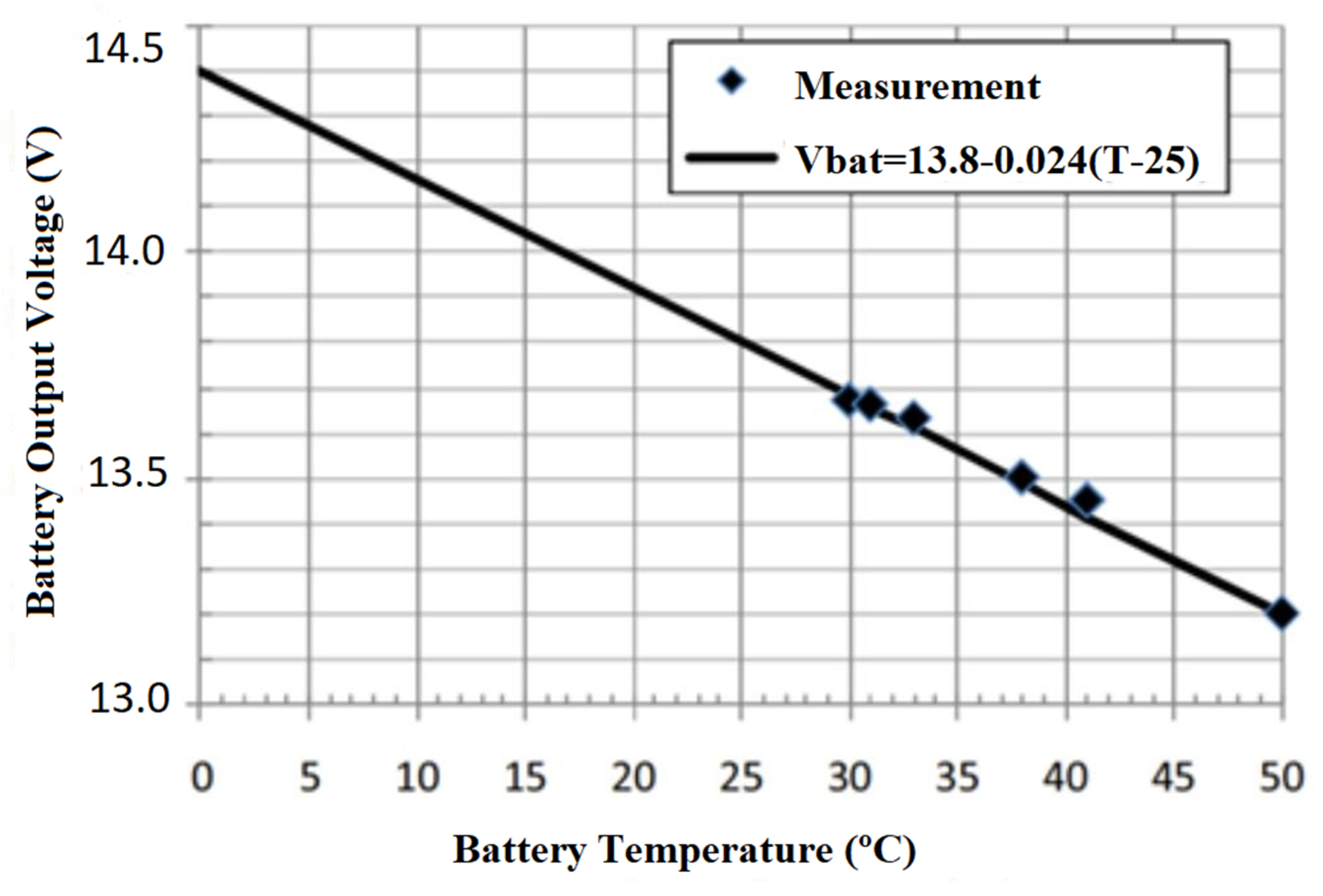
- The charging systems of the batteries of the EVs depend on multiple factors, such as the design of the batteries, their charge status, temperature, former cycle history, and usage. There are two main charging systems, namely constant current charging, and constant current–constant voltage charging. The constant current charging often results in overcharging the battery, thereby overheating it and damages it. On the other hand, the constant current–constant voltage method eliminates the risk of overcharging but increases the charging time of the battery. As an optimization, the battery is charged at a constant current until a preset voltage is reached, and then charged at a constant voltage. A battery management system (BMS) is employed in the system to act as an overall controller of the battery health by monitoring its charge status, temperature, battery cycles, and other such parameters, providing data to and communication with other modules.
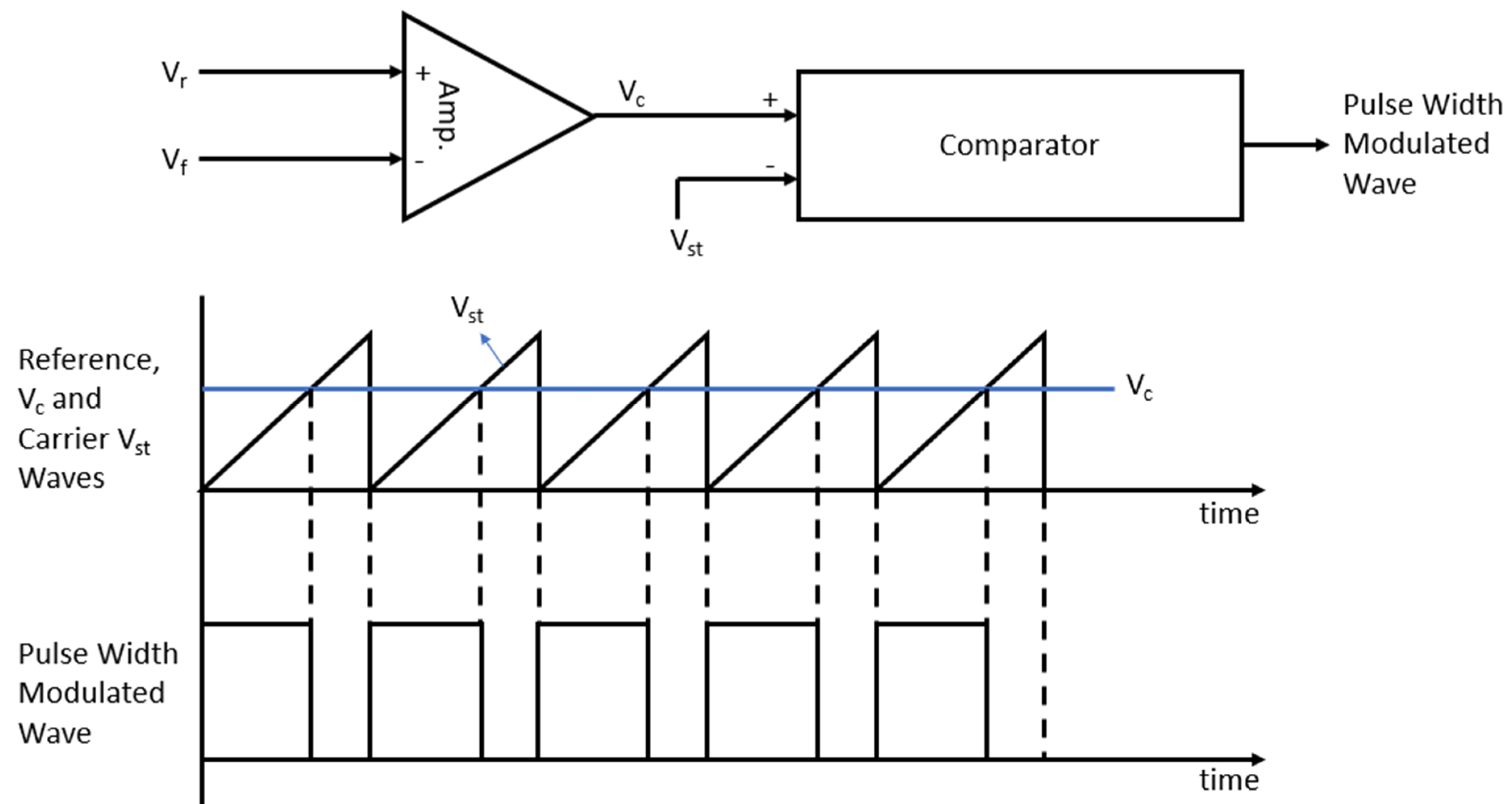
- The bidirectional AC/DC power converter topologies used in the charging–discharging systems of batteries in V2G and V2H technology are classified into isolated and non-isolated converters on the basis of the presence or absence of a transformer between input and output to provide isolation. The converters use either pulse width modulation (PWM) or frequency modulation (FM) to control the output voltage.
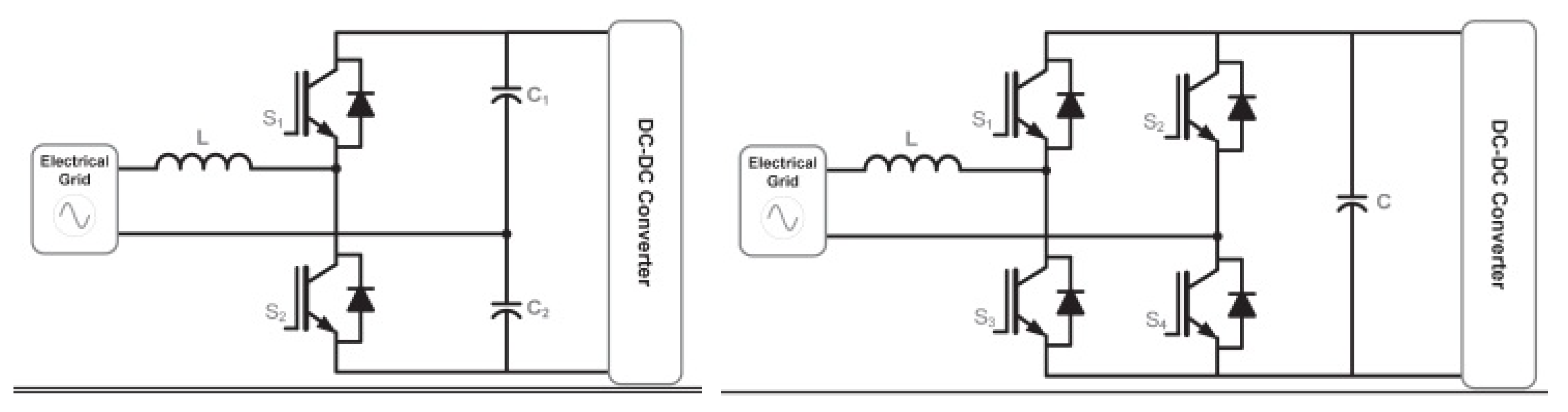
- The bidirectional AC/DC converters can be either half-bridge or full-bridge. In both cases, buck and boost converters are employed to reduce or enhance the voltage level.
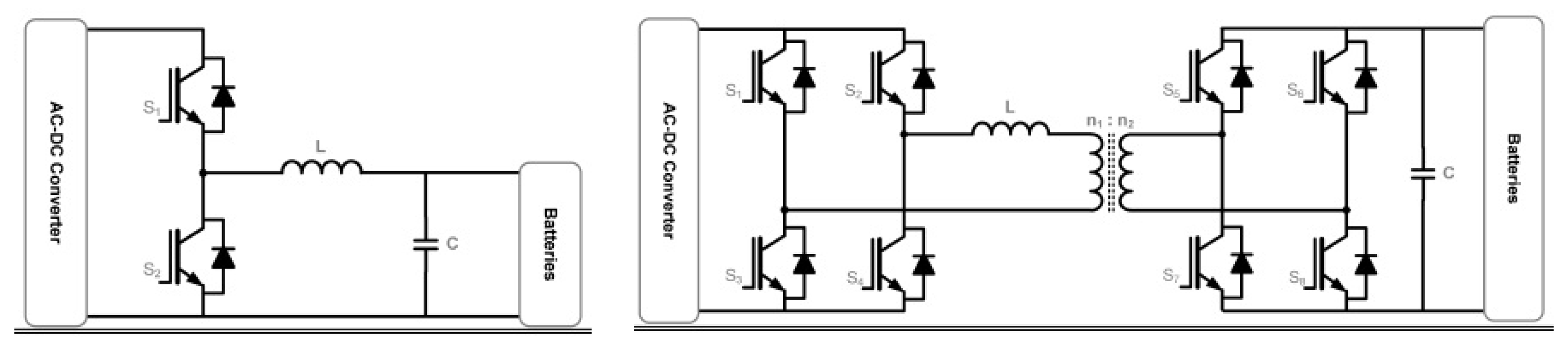
- The voltage level of the receiver must be less than that of the supplier. Hence a definite voltage level must be maintained in the vehicle’s battery in order to supply energy to or extract energy from the grid. Otherwise, a definite current level must be maintained to protect the battery, along with ensuring fast charging. These conditions are met using a bidirectional buck–boost isolated converter, which can alter the voltage levels as and when required.
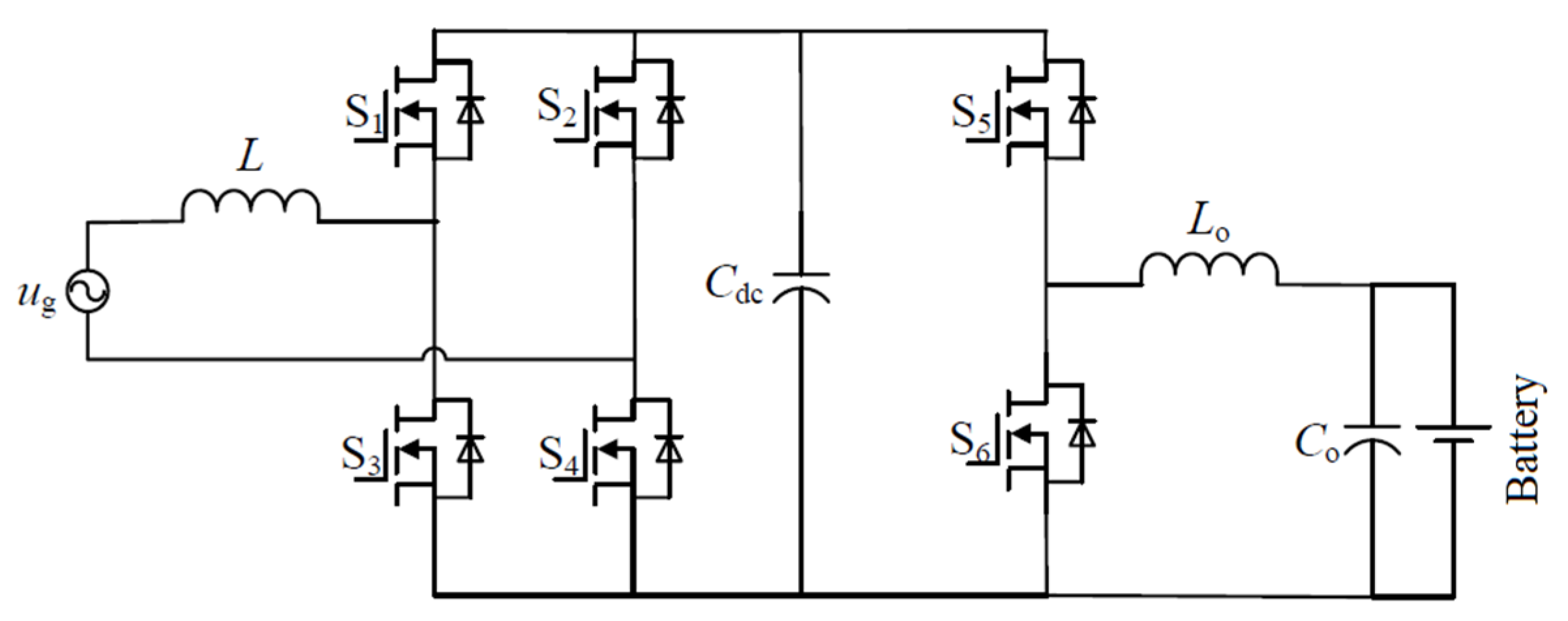
- A non-isolated charging topology with PWM control can also be employed with bidirectional DC/DC buck–boost converters to raise or lower the voltage levels.
- Multiple units of DC/DC buck–boost converters can also be cascaded to perform multi-step reduction or amplification of voltage in case of the non-isolated charging topology with PWM control.
- The charging topology can also be composed of two-stages isolated by a transformer. The two stages can be formed either with a PWM converter and an active double bride converter, or with a PWM converter and a series resonance converter.
- Buck–boost converters are extensively employed in the V2G operation to obtain the desired voltage level in various stages of the energy transfer process.
- For a successful and organized transfer of energy in the V2G technology, a good communication is required between the vehicle and the grid operator. There are predefined communication standards set for this purpose. The standards vary according to the connector structures, the communication methods, the charging topologies, and the safety and the interoperability standards.
- In the V2G technology, both AC/DC and DC/DC converters are indispensable. There can be numerous topologies of these converters. For each type of AC/DC converter, the power consumption, power factor, number of switches, type of filter, merits and demerits, and THD are explored. Similarly, for the various types of DC/DC converters, the type of input, power consumption, efficiency, switching frequency, and merits and demerits are examined.
- Finally, an extensive SWOT analysis of the V2G technology is made, wherein it is evident that, despite the few weaknesses and threats, this emerging technology has a promising future and can contribute towards building a greener and much more efficient energy infrastructure.
7. Conclusions
Author Contributions
Funding
Acknowledgments
Conflicts of Interest
References
- Ota, Y.; Taniguchi, H.; Baba, J.; Yokoyama, A. Implementation of autonomous distributed V2G to electric vehicle and DC charging system. Electr. Power Syst. Res. 2015, 120, 177–183. [Google Scholar] [CrossRef]
- Winkler-Goldstein, R.; Rastetter, A. Power to Gas: The Final Breakthrough for the Hydrogen Economy? Green 2013, 3. [Google Scholar] [CrossRef]
- Xueqin, L.; Fuzhen, H.; Gang, L.; Rongfu, Q. The challenges of technologies for fuel cell and its application on vehicles. In Proceedings of the 2009 IEEE 6th International Power Electronics and Motion Control Conference, Wuhan, China, 17–20 May 2009; p. 2328. [Google Scholar] [CrossRef]
- Bossel, U. Does a Hydrogen Economy Make Sense? Proc. IEEE 2006, 94, 1826–1837. [Google Scholar] [CrossRef]
- White, C.D.; Zhang, K.M. Using Vehicle-to-Grid Technology for Frequency Regulation and Peak-Load Reduction. J. Power Sources 2011, 196, 3972–3979. [Google Scholar] [CrossRef]
- Kisacikoglu, M.C.; Ozpineci, B.; Tolbert, L.M. EV/PHEV Bidirectional Charger Assessment for V2G Reactive Power Operation. IEEE Trans. Power Electron. 2013, 28, 5717–5727. [Google Scholar] [CrossRef]
- De Freige, M.; Ross, M.; Joos, G.; Dubois, M. Power & Energy Ratings Optimization in a Fast-Charging Station for PHEV Batteries. In Proceedings of the 2011 IEEE International Electric Machines & Drives Conference (IEMDC), Victoria, BC, Canada, 24–26 August 2011; p. 486. [Google Scholar] [CrossRef]
- Pearre, N.S.; Ribberink, H. Review of research on V2X technologies, strategies, and operations. Renew. Sustain. Energy Rev. 2019, 105, 61–70. [Google Scholar] [CrossRef]
- Arancibia, A.; Strunz, K. Modeling of an Electric Vehicle Charging Station for Fast DC Charging. In Proceedings of the 2012 IEEE International Electric Vehicle Conference, Greenville, SC, USA, 4–8 March 2012; pp. 1–6. [Google Scholar] [CrossRef]
- Yilmaz, M.; Krein, P.T. Review of Battery Charger Topologies, Charging Power Levels, and Infrastructure for Plug-In Electric and Hybrid Vehicles. IEEE Trans. Power Electron. 2013, 28, 2151–2169. [Google Scholar] [CrossRef]
- Musavi, F.; Edington, M.; Eberle, W.; Dunford, W.G. Energy Efficiency in Plug-in Hybrid Electric Vehicle Chargers: Evaluation and Comparison of Front end AC-DC Topologies. In Proceedings of the 2011 IEEE Energy Conversion Congress and Exposition, Phoenix, AZ, USA, 17–22 September 2011; pp. 273–278. [Google Scholar] [CrossRef]
- Kwon, M.; Jung, S.; Choi, S. A high efficiency bi-directional EV charger with seamless mode transfer for V2G and V2H application. In Proceedings of the 2015 IEEE Energy Conversion Congress and Exposition (ECCE), Montreal, QC, Canada, 20–24 September 2015; pp. 5394–5396. [Google Scholar] [CrossRef]
- Rahman, I.; Vasant, P.M.; Singh BS, M.; Abdullah-Al-Wadud, M.; Adnan, N. Review of Recent Trends in Optimization Techniques for Plug-in Hybrid, And Electric Vehicle Charging Infrastructures. Renew. Sustain. Energy Rev. 2016, 58, 1039–1047. [Google Scholar] [CrossRef]
- Colak, I.; Kabalci, E.; Bayindir, R. Review of multilevel voltage source inverter topologies and control schemes. Energy Convers. Manag. 2011, 52, 1114–1115. [Google Scholar] [CrossRef]
- Colak, I.; Kabalci, E.; Fulli, G.; Lazarou, S. A survey on the contributions of power electronics to smart grid systems. Renew. Sustain. Energy Rev. 2015, 47, 562–579. [Google Scholar] [CrossRef]
- Fathabadi, H. Utilization of electric vehicles and renewable energy sources used as distributed generators for improving characteristics of electric power distribution systems. Energy 2015, 90, 1100–1111. [Google Scholar] [CrossRef]
- Erb, D.C.; Onar, O.C.; Khaligh, A. Bi-Directional Charging Topologies for Plug-In Hybrid Electric Vehicles. In Proceedings of the 2010 Twenty-Fifth Annual IEEE Applied Power Electronics Conference and Exposition (APEC), Palm Springs, CA, USA, 21–25 February 2010; pp. 2066–2067. [Google Scholar] [CrossRef]
- Jiang, J.; Bao, Y.; Wang, L. Topology of a Bidirectional Converter for Energy Interaction between Electric Vehicles and the Grid. Energies 2014, 7, 4858. [Google Scholar] [CrossRef]
- Gao, S.K.T.C.; Liu, C.; Wu, D. Optimal Control Framework and Scheme for Integrating Plug-in Hybrid Electric Vehicles into Grid. J. Asian Electr. Veh. 2011, 9, 1473–1479. [Google Scholar] [CrossRef]
- Pinto, J.G.; Monteiro, V.; Gonçalves, H.; Exposto, B.; Pedrosa, D.; Couto, C.; Afonso, J.L. Bidirectional battery charger with Grid-to-Vehicle, Vehicle-to-Grid and Vehicle-to-Home technologies. In Proceedings of the IECON 2013—39th Annual Conference of the IEEE Industrial Electronics Society, Vienna, Austria, 10–13 November 2013; pp. 5934–5936. [Google Scholar] [CrossRef]
- Narula, A.; Verma, V. Bi-Directional Trans-Z Source Boost Converter for G2V/V2G Applications. In Proceedings of the 2017 IEEE Transportation Electrification Conference (ITEC-India), Pune, India, 13–16 December 2017; pp. 1–6. [Google Scholar] [CrossRef]
- Liu, H.; Hu, Z.; Song, Y.; Wang, J.; Xie, X. Vehicle-to-Grid Control for Supplementary Frequency Regulation Considering Charging Demands. IEEE Trans. Power Syst. 2015, 30, 3110. [Google Scholar] [CrossRef]
- Hota, A.R.; Juvvanapudi, M.; Bajpai, P. Issues and solution approaches in PHEV integration to the smart grid. Renew. Sustain. Energy Rev. 2014, 30, 217–229. [Google Scholar] [CrossRef]
- Bahrami, S.; Wong, V.W. A potential game framework for charging PHEVs in smart grid. In Proceedings of the 2015 IEEE Pacific Rim Conference on Communications, Computers and Signal Processing (PACRIM), Victoria, BC, Canada, 24–26 August 2015; p. 28. [Google Scholar] [CrossRef]
- Harighi, T.; Bayindir, R.; Padmanaban, S.; Mihet-Popa, L.; Hossain, E. An Overview of Energy Scenarios, Storage Systems and the Infrastructure for Vehicle-to-Grid Technology. Energies 2018, 11, 2174. [Google Scholar] [CrossRef]
- Colak, I.; Fulli, G.; Sagiroglu, S.; Yesilbudak, M.; Covrig, C.F. Smart grid projects in Europe: Current status, maturity and future scenarios. Appl. Energy 2015, 152, 58–70. [Google Scholar] [CrossRef]
- Colak, I.; Sagiroglu, S.; Fulli, G.; Yesilbudak, M.; Covrig, C.F. A Survey on the Critical Issues in Smart Grid Technologies. Renew. Sustain. Energy Rev. 2016, 54, 396–405. [Google Scholar] [CrossRef]
- Bayindir, R.; Colak, I.; Fulli, G.; Demirtas, K. Demirtas K. Smart grid technologies and applications. Renew. Sustain. Energy Rev. 2016, 66, 499–516. [Google Scholar] [CrossRef]
- Ansari, K.; Feng, Y. Design of an Integration Platform for V2X Wireless Communications and Positioning Supporting C-ITS Safety Applications. J. Glob. Position. Syst. 2013, 12, 38–52. [Google Scholar] [CrossRef][Green Version]
- Ghods, A.; Severi, S.; Abreu, G. Localization in V2X communication networks. In Proceedings of the 2016 IEEE Intelligent Vehicles Symposium (IV), Gothenburg, Sweden, 19–22 June 2016; pp. 5–9. [Google Scholar] [CrossRef]
- Siegel, J.E. CloudThink and the Avacar: Embedded Design to Create Virtual Vehicles for Cloud-Based Informatics, Telematics, and Infotainment; Cambridge Massachusetts Inst. Technol: Cambridge, MA, USA, 2013. [Google Scholar]
- Wilhelm, E.; Siegel, J.; Mayer, S.; Sadamori, L.; Dsouza, S.; Chau, C.K.; Sarma, S. Cloudthink: A scalable secure platform for mirroring transportation systems in the cloud. Transport 2015, 30, 320–329. [Google Scholar] [CrossRef]
- Rinaldi, S.; Pasetti, M.; Trioni, M.; Vivacqua, G. On the Integration of E-Vehicle Data for Advanced Management of Private Electrical Charging Systems. In Proceedings of the 2017 IEEE International Instrumentation and Measurement Technology Conference (I2MTC), Turin, Italy, 22–25 May 2017; pp. 1–6. [Google Scholar] [CrossRef]
- Siegel, J.E.; Erb, D.C.; Sarma, S.E. A Survey of the Connected Vehicle Landscape—Architectures, Enabling Technologies, Applications, and Development Areas. IEEE Trans. Intell. Transp. Syst. 2018, 19, 2391–2406. [Google Scholar] [CrossRef]
- Liu, H.; Yang, Y.; Qi, J.; Li, J.; Wei, H.; Li, P. Frequency droop control with scheduled charging of electric vehicles. IET Gener. Transm. Distrib. 2016, 11, 649–656. [Google Scholar] [CrossRef]
- Orihara, D.; Kimura, S.; Saitoh, H. Frequency Regulation by Decentralized V2G Control with Consensus-Based SOC Synchronization. IFAC-PapersOnLine 2018, 51, 604–606. [Google Scholar] [CrossRef]
- Tuttle, D.P.; Fares, R.L.; Baldick, R.; Webber, M.E. Plug-In Vehicle to Home (V2H) duration and power output capability. In Proceedings of the 2013 IEEE Transportation Electrification Conference and Expo (ITEC), Detroit, MI, USA, 16–19 June 2013; pp. 1–7. [Google Scholar] [CrossRef]
- Han, S.; Han, S.; Sezaki, K. Estimation of achievable power capacity from plug-in electric vehicles for V2G frequency regulation: Case studies for market participation. IEEE Trans. Smart Grid 2011, 2, 632–641. [Google Scholar] [CrossRef]
- Liu, Y.J.C.T.; Chen, H.W.; Chang, T.K.; Lan, P.H. Power quality measurements of low-voltage distribution system with smart electric vehicle charging infrastructures. In Proceedings of the 2014 16th International Conference on Harmonics and Quality of Power (ICHQP), Bucharest, Romania, 25–28 May 2014; pp. 631–635. [Google Scholar] [CrossRef]
- Berthold, F.; Ravey, A.; Blunier, B.; Bouquain, D.; Williamson, S.; Miraoui, A. Design and Development of a Smart Control Strategy for Plug-In Hybrid Vehicles Including Vehicle-to-Home Functionality. IEEE Trans. Transp. Electrif. 2015, 1, 168–177. [Google Scholar] [CrossRef]
- Weiller, C. Plug-in hybrid electric vehicle impacts on hourly electricity demand in the United States. Energy Policy 2011, 39, 3766–3778. [Google Scholar] [CrossRef]
- Liu, C.; Chau, K.T.; Wu, D.; Gao, S. Opportunities and challenges of vehicle-to-home, vehicle-to-vehicle, and vehicle-to-grid technologies. Proc. IEEE 2013, 101, 2409–2419. [Google Scholar] [CrossRef]
- Ahmad, F.; Alam, M.S.; Asaad, M. Developments in EVs charging infrastructure and energy management system for smart microgrids including EVs. Sustain. Cities Soc. 2017, 35, 552–564. [Google Scholar] [CrossRef]
- Mwasilu, F.; Justo, J.J.; Kim, E.K.; Do, T.D.; Jung, J.W. Electric vehicles and smart grid interaction: A review on vehicle to grid and renewable energy sources integration. Renew. Sustain. Energy Rev. 2014, 34, 501–516. [Google Scholar] [CrossRef]
- Galus, M.D.; Koch, S.; Andersson, G. Provision of load frequency control by PHEVS, controllable loads, and a cogeneration unit. IEEE Trans. Ind. Electron. 2011, 58, 4568–4582. [Google Scholar] [CrossRef]
- Un-Noor, F.; Padmanaban, S.; Mihet-Popa, L.; Mollah, N.M.; Hossain, E. A Comprehensive Study of Key Electric Vehicle (EV) Components, Technologies, Challenges, Impacts, and Future Direction of Development. Energies 2017, 10, 1217. [Google Scholar] [CrossRef]
- Ota, Y.; Taniguchi, H.; Nakajima, T.; Liyanage, K.M.; Baba, J.; Yokoyama, A. Autonomous distributed V2G (Vehicle-to-Grid) satisfying scheduled charging. IEEE Trans. Smart Grid 2012, 3, 559–564. [Google Scholar] [CrossRef]
- Shimizu, K.; Masuta, T.; Ota, Y.; Yokoyama, A. A New Load Frequency Control Method in Power System Using Vehicle-To-Grid System Considering Users’ Convenience. In Proceedings of the 17th Power System Computation Conference, Stockholm, Sweden, 22–26 August 2011; pp. 1–7. [Google Scholar]
- Ferreira, R.J.; Miranda, L.M.; Araújo, R.E.; Lopes, J.P. A New Bi-Directional Charger For Vehicle-To-Grid Integration. In Proceedings of the 2011 2nd IEEE PES International Conference and Exhibition on Innovative Smart Grid Technologies, Manchester, UK, 5–7 December 2011; pp. 1–5. [Google Scholar] [CrossRef]
- Hossain, E.; Murtaugh, D.; Mody, J.; Faruque, H.M.; Sunny, M.S.; Mohammad, N. A Comprehensive Review on Second-Life Batteries: Current State, Manufacturing Considerations, Applications, Impacts, Barriers & Potential Solutions, Business Strategies, and Policies. IEEE Access 2019, 7, 73215–73252. [Google Scholar] [CrossRef]
- McLoughlin, F.; Conlon, M. Secondary Re-Use of Batteries from Electric Vehicles for Building Integrated Photo-Voltaic (BIPV) Applications; Dublin Institute of Technology: Dublin, Ireland, 2015. [Google Scholar]
- Andersen, P.B.; Garcia-Valle, R.; Kempton, W. A Comparison of Electric Vehicle Integration Projects. In Proceedings of the 2012 3rd IEEE PES Innovative Smart Grid Technologies Europe (ISGT Europe), Berlin, Germany, 14–17 October 2012; pp. 1–7. [Google Scholar] [CrossRef]
- Su, G.J.; Tang, L. Using Onboard Electrical Propulsion System to Provide Plug-incharging, V2G and Mobile Power Generation Capabilities for Hevs. In Proceedings of the IEEE Electric Vehicle Conference, Greenville, SC, USA, 4–8 March 2012; pp. 1–8. [Google Scholar] [CrossRef]
- Madawala, U.K.; Thrimawithana, D.J. A Bidirectional Inductive Power Interface for Electric Vehicles in V2G Systems. IEEE Trans. Ind. Electron. 2011, 58, 4789–4796. [Google Scholar] [CrossRef]
- Nissan Leaf—Battery Capacity Loss. Available online: http://www.electricvehiclewiki.com/wiki/battery-capacity-loss/ (accessed on 17 September 2019).
- Harighi, T.; Padmanaban, S.; Bayindir, R.; Hossain, E.; Holm-Nielsen, J.B. Electric Vehicle Charge Stations Location Analysis and Determination—Ankara (Turkey) Case Study. Energies 2019, 12, 3472. [Google Scholar] [CrossRef]
- Heydarian-Forushani, E.; Golshan, M.; Shafie-khah, M. Flexible interaction of plug-in electric vehicle parking lots for efficient wind integration. Appl. Energy 2016, 179, 338–349. [Google Scholar] [CrossRef]
- He, Y.; Kockelman, K.M.; Perrine, K.A. Optimal locations of U.S. fast charging stations for long-distance trip completion by battery electric vehicles. J. Clean. Prod. 2019, 214, 452–461. [Google Scholar] [CrossRef]
- Zarandi, M.F.; Davari, S.; Sisakht, S.H. The large scale maximal covering location problem. Sci. Iran. 2011, 18, 1564–1570. [Google Scholar] [CrossRef]
- Cui, S.; Zhao, H.; Zhang, C. Locating Charging Stations of Various Sizes with Different Numbers of Chargers for Battery Electric Vehicles. Energies 2018, 11, 3056. [Google Scholar] [CrossRef]
- Said, D.; Cherkaoui, S.; Khoukhi, L. Queuing model for EVs charging at public supply stations. In Proceedings of the 9th International Wireless Communications and Mobile Computing Conference (IWCMC), Cagliari, Italy, 1–5 July 2013; pp. 65–70. [Google Scholar] [CrossRef]
- Said, D.; Cherkaoui, S.; Khoukhi, L. Multi-priority queuing for electric vehicles charging at public supply stations with price variation: Multi-priority queuing EV charging with price variation. Wirel. Commun. Mob. Comput. 2014, 15. [Google Scholar] [CrossRef]
- He, F.; Yin, Y.; Lawphongpanich, S. Network equilibrium models with battery electric vehicles. Transp. Res. Part. B Methodol. 2014, 67, 306–319. [Google Scholar] [CrossRef]
- Habib, S.; Kamran, M.; Rashid, U. Impact analysis of vehicle-to-grid technology and charging strategies of electric vehicles on distribution networks—A review. J. Power Sources 2015, 277, 205–214. [Google Scholar] [CrossRef]
- Liu, G.; Kang, L.; Luan, Z.; Qiu, J.; Zheng, F. Charging Station and Power Network Planning for Integrated Electric Vehicles (EVs). Energies 2019, 12, 2595. [Google Scholar] [CrossRef]
- Aveklouris, A.; Nakahira, Y.; Vlasiou, M.; Zwart, B. Electric vehicle charging: A queueing approach. ACM SIGMETRICS Perform. Eval. Rev. 2017, 45, 33–35. [Google Scholar] [CrossRef]
- Devecı, F.; Boztepe, M. Design of Temperature Compensated Charger for Lead-Acid Battery. In Proceedings of the National Conference on Electrical, Electronics and Computer Engineering, Bursa, Turkey, 2–5 December 2010; pp. 269–272. [Google Scholar]
- Bhatti, A.R.; Salam, Z.; Aziz MJ, B.A.; Yee, K.P.; Ashique, R.H. Electric vehicles charging using photovoltaic: Status and technological review. Renew. Sustain. Energy Rev. 2016, 54, 34–47. [Google Scholar] [CrossRef]
- Li, S.; Zhang, C.; Xie, S. Research on Fast Charge Method for Lead-Acid Electric Vehicle Batteries. In Proceedings of the International Workshop on Intelligent Systems and Applications, Wuhan, China, 23–24 May 2009; pp. 1–5. [Google Scholar]
- Huet, F. A review of impedance measurements for determination of the state-of-charge or state-of-health of secondary batteries. J. Power Sources 1998, 70, 56–69. [Google Scholar] [CrossRef]
- Huria, T.; Ceraolo, M.; Gazzarri, J.; Jackey, R. Simplified Extended Kalman Filter Observer for SOC Estimation of Commercial Power-Oriented LFP Lithium Battery Cells. SAE Tech. Pap. 2013, 1–10. [Google Scholar] [CrossRef]
- Andre, D.; Meiler, M.; Steiner, K.; Wimmer, C.; Soczka-Guth, T.; Sauer, D.U. Characterization of high-power lithium-ion batteries by electrochemical impedance spectroscopy. I. Experimental investigation. J. Power Sources 2011, 196, 5334–5338. [Google Scholar] [CrossRef]
- Wei, X.; Zhu, B.; Xu, W. Internal Resistance Identification in Vehicle Power Lithium-Ion Battery and Application in Lifetime Evaluation. In Proceedings of the International Conference on In Measuring Technology and Mechatronics Automation, Zhangjiajie, China, 11–12 April 2009; pp. 388–392. [Google Scholar] [CrossRef]
- Zhang, Y.; Wang, C.Y.; Tang, X. Cycling Degradation of an Automotive LiFePO4 Lithium-Ion Battery. J. Power Sources 2011, 196, 1513–1518. [Google Scholar] [CrossRef]
- Shim, J.; Kostecki, R.; Richardson, T.; Song, X.; Striebel, K.A. Electrochemical Analysis for Cycle Performance and Capacity Fading of a Lithium-Ion Battery Cycled at Elevated Temperature. J. Power Sources 2012, 112, 220–229. [Google Scholar] [CrossRef]
- Peterson, S.B.; Apt, J.; Whitacre, J.F. Lithium-Ion Battery Cell Degradation Resulting from Realistic Vehicle and Vehicle-to-Grid Utilization. J. Power Sources 2010, 195, 2385–2388. [Google Scholar] [CrossRef]
- Hossain, E.; Perez, R.; Nasiri, A.; Bayindir, R. Stability improvement of microgrids in the presence of constant power loads. Int. J. Electr. Power Energy Syst. 2018, 96, 442–456. [Google Scholar] [CrossRef]
- Reddy, B.M.; Samuel, P. A Comparative Analysis of Non-Isolated Bi-directional DC-DC Converters. In Proceedings of the 1st IEEE International Conference on Power Electronics, Intelligent Control. and Energy Systems (ICPEICES-2016), Delhi, India, 4–6 July 2016; pp. 1–6. [Google Scholar]
- Elankurisil, S.A.; Dash, S. Comparison of Isolated and Non-isolated Bi-directional DC-DC Converters. J. Eng. 2011, 21, 2341–2347. [Google Scholar]
- Mehdipour A, F.S. Comparison of Three Isolated Bi-Directional DC/DC Converter Topologies for Backup Photovoltaic Application. In Proceedings of the 2nd International Conference on Electric Power and Energy Conversion Systems (EPECS), Sharjah, United Arab Emirates, 15–17 November 2011; pp. 1–5. [Google Scholar]
- Xu, Y.C.Y.; Huang, A.Q. Five Level Bi-Directional Converter for Renewable Energy Generation. In Proceedings of the IECON 2014—40th Annual Conference of the IEEE Industrial Electronics Society, Dallas, TX, USA, 29 October–1 November 2014; pp. 5514–5516. [Google Scholar]
- Rei, R.J.; Soares, F.J.; Almeida, P.R.; Lopes, J.P. Grid Interactive Charging Control for Plug-in Electric Vehicles. In Proceedings of the 13th International IEEE Conference on Intelligent Transportation Systems, Funchal, Portugal, 19–22 September 2010; p. 386. [Google Scholar]
- Freire, R.; Delgado, J.; Santos, J.M.; De Almeida, A.T. Integration of Renewable Energy Generation with EV Charging Strategies to Optimize Grid Load Balancing. In Proceedings of the 13th International IEEE Conference on Intelligent Transportation Systems, Funchal, Portugal, 19–22 September 2010; pp. 392–395. [Google Scholar]
- Ferreira, J.C.; Trigo, P.; da Silva, A.R.; Coelho, H.; Afonso, J.L. Simulation of Electrical Distributed Energy Resources for Electrical Vehicles Charging Process Strategy. In Proceedings of the Second Brazilian Workshop on Social Simulation (BWSS 2010), Washington, DC, USA, 24–25 October 2010; pp. 82–89. [Google Scholar]
- Hernández, S.S.; Galindo, P.P.; López, A.Q. Technology to integrate EV inside smart grids. In Proceedings of the 2010 7th International Conference on the European Energy Market, Madrid, Spain, 23–25 June 2010; pp. 1–6. [Google Scholar]
- Jarnut, M.; Benysek, G. Application of Power Electronics Devices in Smart Grid and V2G(Vehicle to Grid) technologies. Prz. Elektrotech. 2010, 86, 93–94. [Google Scholar]
- Kisacikoglu, M.C.; Ozpineci, B.; Tolbert, L.M. Effects of V2G Reactive Power Compensation on the Component Selection in an EV or PHEV Bidirectional Charger. In Proceedings of the IEEE Energy Conversion Congress and Exposition, Atlanta, GA, USA, 12–16 September 2010; pp. 870–877. [Google Scholar]
- Pinto, J.G.; Monteiro, V.; Gonçalves, H.; Afonso, J.L. Onboard reconfigurable battery charger for electric vehicles with traction-to-auxiliary mode. IEEE Trans. Veh. Technol. 2014, 63, 1104–1113. [Google Scholar] [CrossRef]
- Khan, M.A.; Husain, I.; Sozer, Y. Bi-directional DC-DC converter with overlapping input and output voltage ranges and vehicle to grid energy transfer capability. In Proceedings of the 2012 IEEE International Electric Vehicle Conference (IEVC), Greenville, SC, USA, 4–8 March 2012; pp. 1–7. [Google Scholar]
- Das, P.; Pahlevaninezhad, M.; Moschopoulos, G. Analysis and Design of a New AC–DC Single-Stage Full-Bridge PWM Converter with Two Controllers. IEEE Trans. Ind. Electron. 2013, 60, 4930–4946. [Google Scholar] [CrossRef]
- Wijeratne, D.S.; Moschopoulos, G. A Comparative Study of Two Buck-Type Three-Phase Single-Stage AC–DC Full-Bridge Converters. IEEE Trans. Power Electron. 2014, 29, 1632–1645. [Google Scholar] [CrossRef]
- Xie, Y.; Sun, J.; Freudenberg, J.S. Power flow characterization of a bidirectional galvanically isolated high-power DC/DC converter over a wide operating range. IEEE Trans. Power Electron. 2010, 25, 54–66. [Google Scholar]
- Shi, X.; Jiang, J.; Guo, X. An efficiency-optimized isolated bidirectional DC-DC converter with extended power range for energy storage systems in microgrids. Energies 2013, 6, 27–44. [Google Scholar] [CrossRef]
- Kanaan, H.Y.; Caron, M.; Al-Haddad, K. Design and implementation of a two-stage grid-connected high efficiency power load emulator. IEEE Trans. Power Electron. 2014, 29, 3997–4006. [Google Scholar] [CrossRef]
- Zhao, B.; Song, Q.; Liu, W.; Sun, Y. Overview of dual-active bridge isolated bidirectional dc-dc converter for high frequency-link power-conversion system. IEEE Trans. Power Electron. 2014, 29, 4091–4106. [Google Scholar] [CrossRef]
- Lu, L.; Han, X.; Li, J.; Hua, J.; Ouyang, M. A review on the key issues for lithium-ion battery management in electric vehicles. J. Power Sources 2013, 226, 272–288. [Google Scholar] [CrossRef]
- He, Y.; Venkatesh, B.; Guan, L. Optimal scheduling for charging and discharging of electric vehicles. IEEE Trans. Smart Grid 2012, 3, 1095–1105. [Google Scholar] [CrossRef]
- Wei, Z.; Li, Y.; Zhang, Y.; Cai, L. Intelligent parking garage EV charging scheduling considering battery charging characteristic. IEEE Trans. Ind. Electron. 2018, 65, 2806–2816. [Google Scholar] [CrossRef]
- Mahmud, K.; Town, G.E.; Morsalin, S.; Hossain, M.J. Integration of electric vehicles and management in the internet of energy. Renew. Sustain. Energy Rev. 2018, 82, 4179–4203. [Google Scholar] [CrossRef]
- Saltanovs, R.; Krivchenkov, A.; Krainyukov, A. Analysis of effective wireless communications for V2G applications and mobile objects. In Proceedings of the 58th International Scientific Conference on Power and Electrical Engineering of Riga Technical University (RTUCON), Riga, Latvia, 12–13 October 2017. [Google Scholar]
- Du, Y.; Lukic, S.; Jacobson, B.; Huang, A. Review of high power isolated bi-directional DC-DC converters for PHEV/EV DC charging infrastructure. In Proceedings of the 2011 IEEE Energy Conversion Congress and Exposition, Phoenix, AZ, USA, 16–21 September 2011; pp. 553–558. [Google Scholar]
- Guille, C.; Gross, G. A conceptual framework for the vehicle-to-grid (V2G) implementation. Energy Policy 2009, 37, 4379–4390. [Google Scholar] [CrossRef]
- Rezaee, S.; Farjah, E. A DC–DC Multiport Module for Integrating Plug-In Electric Vehicles in a Parking Lot: Topology and Operation. IEEE Trans. Power Electron. 2014, 29, 5688–5695. [Google Scholar] [CrossRef]
- Richardson, D.B. Electric Vehicles and the Electric Grid: A Review of Modeling Approaches, Impacts, and Renewable Energy Integration. Renew. Sustain. Energy Rev. 2013, 19, 247–248. [Google Scholar] [CrossRef]
- Tuttle, D.P.; Baldick, R. The evolution of plug-in electric vehicle-grid interactions. IEEE Trans. Smart Grid 2012, 3, 500–506. [Google Scholar] [CrossRef]
- Guo, H.; Wu, Y.; Bao, F.; Chen, H.; Ma, M. A unique batch authentication protocol for vehicle-to-grid communications. IEEE Trans. Smart Grid 2011, 2, 707–708. [Google Scholar] [CrossRef]
- Ehsani, M.; Falahi, M.; Lotfifard, S. Vehicle to grid services: Potential and applications. Energies 2012, 5, 4076–4090. [Google Scholar] [CrossRef]
- Keyhani, H.; Toliyat, H.A. A ZVS single-inductor multi-input multi output DC-DC converter with the step up/down capability. In Proceedings of the 2013 IEEE Energy Conversion Congress and Exposition, Denver, CO, USA, 15–19 September 2013; pp. 5546–5547. [Google Scholar]
- Schmutzler, J.; Gröning, S.; Wietfeld, C. Management of Distributed Energy Resources in IEC 61850 using Web Services on Devices. In Proceedings of the 2011 IEEE International Conference on Smart Grid Communications (SmartGridComm), Brussels, Belgium, 17–20 October 2011; pp. 315–316. [Google Scholar]
- Schmutzler, J.; Wietfeld, C.; Jundel, S.; Voit, S. A Mutual Charge Schedule Information Model for the Vehicle-to-Grid Communication Interface. In Proceedings of the 2011 IEEE Vehicle Power and Propulsion Conference, Chicago, IL, USA, 5–8 September 2011; pp. 1–6. [Google Scholar]
- Kiokes, G.; Zountouridou, E.; Papadimitriou, C.; Dimeas, A.; Hatziargyriou, N. Papadimitriou, A. In Dimeas, N. Hatziargyriou. Development of an Integrated Wireless Communication System for Connecting Electric Vehicles to the Power Grid. In Proceedings of the 2015 International Symposium on Smart Electric Distribution Systems and Technologies (EDST), Vienna, Austria, 8–11 September 2015; pp. 296–301. [Google Scholar]
- Hu, J.; Morais, H.; Sousa, T.; Lind, M. Electric vehicle fleet management in smart grids: A review of services, optimization and control aspects. Renew. Sustain. Energy Rev. 2016, 56, 1207–1226. [Google Scholar] [CrossRef]
- Bessa, R.J.; Matos, M.A. Economic and technical management of an aggregation agent for electric vehicles: A literature survey. Eur. Trans. Electr. Power 2012, 22, 334–350. [Google Scholar] [CrossRef]
- Ustun, T.S.; Ozansoy, C.R.; Zayegh, A. Implementing vehicle-to-grid (V2G) technology with IEC 61850-7-420. IEEE Trans. Smart Grid 2013, 4, 1180–1187. [Google Scholar] [CrossRef]
- Käbisch, S.; Schmitt, A.; Winter, M.; Heuer, J. Interconnections and Communications of Electric Vehicles and Smart Grids. In Proceedings of the 2010 First IEEE International Conference on Smart Grid Communications, Gaithersburg, MD, USA, 4–6 October 2010; pp. 161–166. [Google Scholar]
- Liu, Y.; Mitchem, S.C. Implementation of V2G Technology Using DC Fast Charging. In Proceedings of the 2013 International Conference on Connected Vehicles and Expo (ICCVE), Las Vegas, NV, USA, 2–6 December 2013; pp. 734–735. [Google Scholar]
- Han, H.; Liu, Y.; Sun, Y.; Wang, H.; Su, M. A Single-Phase Current-Source Bidirectional Converter For V2G Applications. J. Power Electron. 2014, 14, 458–467. [Google Scholar] [CrossRef]
- Su, M.; Li, H.; Sun, Y.; Xiong, W. A High-Efficiency Bidirectional Ac/Dc Topology for V2G Applications. Power Electron. 2014, 14, 899–907. [Google Scholar] [CrossRef]
- Zhao, T.; Li, Y.; Pan, X.; Wang, P.; Zhang, J. Real-time optimal energy and reserve management of electric vehicle fast charging station: Hierarchical game approach. IEEE Trans. Smart Grid 2017, 99, 1–9. [Google Scholar] [CrossRef]
- Verma, A.K.; Singh, B.; Shahani, D.T. Grid to Vehicle and Vehicle to Grid Energy Transfer using Single-Phase Bidirectional AC-DC Converter and Bidirectional DC-DC Converter. In Proceedings of the 2011 International Conference on Energy, Automation and Signal, Bhubaneswa, India, 28–30 December 2011; pp. 1–5. [Google Scholar]
- Pahlevani, M.; Jain, P. A Fast DC-Bus Voltage Controller for Bidirectional Single Phase AC/DC Converters. IEEE Trans. Power Electron. 2015, 30, 4536–4547. [Google Scholar] [CrossRef]
- Peng, T.; Yang, P.; Dan, H.; Wang, H.; Han, H.; Yang, J.; Wheeler, P. A single-phase bidirectional AC/DC Converter for V2G applications. Energies 2017, 10, 881. [Google Scholar] [CrossRef]
- Choi, W.; Han, D.; Morris, C.T.; Sarlioglu, B. Achieving high efficiency using SiC MOSFETs and reduced output filter for grid-connected V2G Inverter. In Proceedings of the IECON 2015—41st Annual Conference of the IEEE Industrial Electronics Society, Yokohama, Japan, 9–12 November 2015; Volume 201, pp. 3052–3056. [Google Scholar]
- Onar, O.C.; Kobayashi, J.; Erb, D.C.; Khaligh, A. A Bidirectional High-Power-Quality Grid Interface with a Novel Bidirectional Non-Inverted Buck–Boost Converter for PHEVS. IEEE Trans. Veh. Technol. 2012, 61, 2018–2032. [Google Scholar] [CrossRef]
- Jauch, F.; Biela, J. Single-phase single-stage bidirectional isolated ZVS AC-DC converter with PFC. In Proceedings of the 2012 15th International Power Electronics and Motion Control Conference (EPE/PEMC), Novi Sad, Serbia, 4–6 September 2012; Volume 5, pp. 1–8. [Google Scholar]
- Sun, Y.; Liu, W.; Su, M.; Li, X.; Wang, H.; Yang, J. A Unified Modeling and Control of a Multi-Functional Current Source-Typed Converter for V2G Application. Elect. Power Syst. Res. 2014, 106, 12–19. [Google Scholar] [CrossRef]
- Hegazy, O.; Van Mierlo, J.; Lataire, P. Control and Analysis of An Integrated Bidirectional DC/AC and DC/DC Converters for Plug-In Hybrid Electric Vehicle Applications. J. Power Electron. 2011, 11, 408–410. [Google Scholar] [CrossRef]


| Power Flow | kW | Vehicle-to-X | Objective |
|---|---|---|---|
| Bi-directional | 5–10 | Vehicle-to-home (V2H) | It is used in case of emergency energy demand and for storage energy in the battery |
| Bi-directional | 10–15 | Vehicle-to-building (V2B) | It is used in case of emergency energy demand |
| Bi-directional | 15–30 | Vehicle-to-grid (V2G) | It is used to participate in the large scale energy market |
| Bi-Directional AC/DC Inverter Topology | Power | DC Bus Battery Voltage | Number of Switching Devices | Filter | Power Factor | Total Harmonic Distortion (THD) | Advantages/Disadvantages | Ref. Number |
|---|---|---|---|---|---|---|---|---|
| Full bridge | 500 W | 60–120 V | 4 IGBTs 4 MOSFETS | LC | 1 | not known | Low efficiency Hard switched | [114] |
| Full bridge | 500 W | 60–120 V | 4 IGBTs | LC | 0.99 | 4.3% | No DC bus capacitor | [114] |
| Full bridge | 3.5 kW | 300–340 V | 4 IGBTs | RLC | 1 | not known | No isolation | [115] |
| Full bridge | 3.6 kW | 270–360 V | 4 IGBTs | L | 0.99 | <3% | Low THD | [116] |
| Full bridge | 3 kW | 120 V | 4 MOSFETS | - | 1 | 4.5% | High THD | [1] |
| Full bridge | 3.3 kW | 400–450 V | 4 IGBTs | LCL | variable | not known | Fast response, compensation | [117] |
| Full bridge | 400 W | 120 V | 4 MOSFETS | LC | variable | 6.15% | High THD, compensation | [118] |
| Three phase full bridge | 20 kW | 800 V | 6 IGBTs | LCL | not known | 3 % | 99% efficiency (due to SIC devices) | [20] |
| Three level | 18 kW | 350 V | 8 MOSFETS | - | 1 | 2.3% | Low THD, more number of switches, | [119] |
| Single state isolation | 3.3 kW | 280–350 V | 8 MOSFETS | 3 LC | 0.98 | <5% | 97% efficiency, complex control | [120] |
| Bi-Directional DC/DC Convertor Topology | Type of Feed | Power | DC Bus Battery Voltage | Number of Switching Devices | Filter | Isolation | Switching Frequency | Efficiency | Advantages/Disadvantages | Ref. Number |
|---|---|---|---|---|---|---|---|---|---|---|
| Buck–boost converter | Current–voltage feed | 500 W | 60–120 V | 2 IGBTs | C | No | 20 kHz | 83% | Low efficiency, high current ripple | [121] |
| Buck–boost converter | Dual current feed | 500 W | 60–120 V | 2 IGBTs | LC | No | 10 kHz | <85% | Low efficiency, high current ripple | [122] |
| Buck–boost converter | Dual current feed | 3.5 kW | 270–360 V | 2 IGBTs | LC | No | 20 kHz | >90% | Fewer components | [123] |
| Buck–boost converter | Current–voltage feed | 1.2 kW | 100–130 V | 2 IGBTs | LC | No | 50 kHz | Not known | Fewer components | [124] |
| Interleaved buck–boost converter | Current–voltage feed | 30 kW | 170–200 V | 4 IGBTs | C | No | 20 kHz | Not known | High power transfer | [125] |
| Interleaved buck–boost converter | Current–voltage feed | 400 W | 120 V | 4 IGBTs | C | No | 20 kHz | >94% | Low power output | [117] |
| Cascaded buck–boost converter | Dual current feed | 9 kW | 350 V | 4 IGBTs | LC | No | 20 kHz | 91% | High transient stability | [126] |
| Dual full bridge converter | Dual voltage feed | 3.3 kW | 230–430 V | 8 IGBTs | CLC | Yes | 250 kHz | Not known | High frequency | [96] |
| Dual full bridge converter | Dual voltage feed | 30 kW | 360 V | 8 IGBTs | C | Yes | 20 kHz | Not known | Compensation | [120] |
| Half full bridge converter | Current–voltage feed | 1 kW | 250–450 V | 6 IGBTs | C | Yes | 100 kHz | 95% | High efficiency, control flexibility | [127] |
© 2019 by the authors. Licensee MDPI, Basel, Switzerland. This article is an open access article distributed under the terms and conditions of the Creative Commons Attribution (CC BY) license (http://creativecommons.org/licenses/by/4.0/).
Share and Cite
Vadi, S.; Bayindir, R.; Colak, A.M.; Hossain, E. A Review on Communication Standards and Charging Topologies of V2G and V2H Operation Strategies. Energies 2019, 12, 3748. https://doi.org/10.3390/en12193748
Vadi S, Bayindir R, Colak AM, Hossain E. A Review on Communication Standards and Charging Topologies of V2G and V2H Operation Strategies. Energies. 2019; 12(19):3748. https://doi.org/10.3390/en12193748
Chicago/Turabian StyleVadi, Seyfettin, Ramazan Bayindir, Alperen Mustafa Colak, and Eklas Hossain. 2019. "A Review on Communication Standards and Charging Topologies of V2G and V2H Operation Strategies" Energies 12, no. 19: 3748. https://doi.org/10.3390/en12193748
APA StyleVadi, S., Bayindir, R., Colak, A. M., & Hossain, E. (2019). A Review on Communication Standards and Charging Topologies of V2G and V2H Operation Strategies. Energies, 12(19), 3748. https://doi.org/10.3390/en12193748