1. Introduction
Model Predictive Control (MPC) has been applied to many different types of energy systems [
1,
2]. In the case of electric machines, the predictive controller can directly command a power converter, typically a Voltage Source Inverter (VSI) yielding a direct digital control scheme [
3] that is often referred to as FSMPC and FCSMPC. This scheme has been recently used in many applications, including multi-phase IMs. A particular configuration for IM control is Predictive Stator Current Control (PSCC), which allows us to deal separately with the electro-mechanical aspects of IM control [
4].
Multi-phase IMs have lower torque variance, lower DC link current harmonics, and better reliability and power distribution per phase compared with three-phase ones. The most frequent control structure is composed by an inner loop for current control and an outer loop for flux and speed control. Voltage modulation techniques (such as PWM and Space Vector) can be used for current control [
5], whereas direct torque control (DTC) uses a switching table to determine the VSI state [
6]. In [
7], a three-phase to five-phase matrix converter is used to feed a five-phase permanent magnet motor using DTC to eliminate current harmonics. The sensor-less case is explored in [
8] for a five-phase interior permanent magnet motor.
The main advantage of predictive schemes is the flexibility to incorporate in the cost function different criteria [
6]. In this way different control objectives can be treated with ease. As in other forms of MPC, the strategy in PSCC is to optimize a certain Loss Function (LF) with respect to the control action at each discrete-time period. The LF of PSCC is primarily designed to penalize deviations of stator currents from their references. It is however possible to include additional terms in the LF to penalize (mostly) energy losses. As a result, the design of the LF dictates much of the closed-loop performance of the system. It must be recalled that PSCC has not the ability to simultaneously minimize all of the factors present in the loss function due to the finite number of control moves and the uniform sampling time [
9,
10]. In fact, one of the reasons for the late popularity of PSCC is its ability to find a compromise solution for colliding objectives present in the LF [
11], unlike previous schemes (PWM, DTC) where such criteria are not explicitly considered.
Due to computation time constraints, most PSCC use a prediction horizon of 2 steps and a control horizon of just 1 move. This means that the traditional Weighting Functions (WF) of MPC contain just one value per LF term [
12]. For this reason, in the IM control literature, instead of functions these values are referred to as weighting factors. Moreover, in most papers these factors are selected off-line and are kept fixed during operation of the IM. Elimination of the WF has been proposed elsewhere (see [
13] for a review) mainly for the Predictive Torque Control (PTC) of conventional (three-phase) IMs.
The proposal of this paper removes the weighting factors by using a min-max decision function where the different sub-spaces,
and
, are given a relative importance based solely on their relative values. With this proposal, the selection of voltage vectors do not need weighting factors that require a cumbersome procedure to tune. In order to cope with conflicting criteria the proposal uses a decision function that compares predicted errors in the torque producing subspace and in the
subspace. The min-max is a special case of fuzzy logic based functions that have been proposed for use with MPC, where the traditional loss functions are replaced by fuzzy decision functions [
14]. To the best of our knowledge the proposal is novel and similar (not exactly the same) schemes have just been applied to torque control in three-phase systems [
13]. Other related works do use fuzzy systems to substitute the model or the controller [
15,
16,
17].
To illustrate the method, in this paper a five-phase drive is considered. This particular system is relevant as the five-phase machine is of interest [
6] and the proposed method seeks a trade-off between losses and dynamic performance. Please notice that the strategy is applicable to other types of systems. In the next section, the basic aspects of PSCC are reviewed, introducing the material that will be considered in the proposal for min-max control. Simulation and experimental results are provided for a five-phase IM in
Section 4 and
Section 5, respectively. From these results, some conclusions are derived at the end of the paper.
2. PSCC for Five-Phase IM
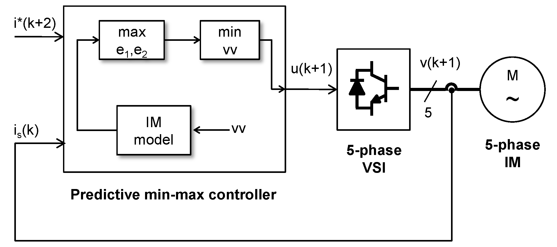
The scheme for PSCC for a multi-phase IM contains a digital processor that decides the control action u indicating the state of the VSI to be held for the whole sampling period . Defining the discrete time k such that , the actuation signal is denoted as . It is well known that a whole sampling time delay is produced due to computations. To account for this, the controller must select at time k the most appropriate value for . The selection is based on minimizing a certain loss function.
Figure 1 shows a diagram where at each discrete-time
k the controller computes
as
where,
is the set of all possible control actions (states of the VSI) and
L is the loss function. The LF must contain a term penalizing the deviation of predicted stator currents
from desired values
, where predictions depend on past control action
that has been previously set and on the actual control action
. Predictions are obtained from a model of the system as
where matrices
A and
B and vector
G are obtained from time-discretization of the systems’ dynamic equations (see [
4] for details).
The necessary penalization of the deviation of
from
is actually done in different planes arising from Clarke’s transformation. By means of this, the stator currents are mapped into an
plane and several
and
z planes. For the five-phase IM that will be used as a case study, just
and
axes need to be used [
18]. With these considerations, the LF can now be defined as
where the predicted errors are computed as
,
. The reference value for the
plane is zero, as it is the normal case. The
reference is given by
,
where
is the electrical frequency determined by the mechanical speed and
I is the amplitude that depends on the mechanical load. Both quantities are supplied to the PSCC by the higher level controller responsible for tracking mechanical variables (speed, torque, position), depending on the application.
The weighting factor
provides the relative importance of
plane regulation over
tracking. The
plane is related to power conversion and the
to losses. In the traditional PSCC,
is treated as a parameter of the controller, selected off-line and kept constant during operation of the drive. The PSCC then uses (
1) to produce
, which is sent to the VSI and kept for the whole sampling period. This is repeated a new the next sampling period, using the receding horizon strategy [
12]. Please note that, as an alternative, virtual voltage vectors have been proposed to produce a sort of modulation producing an average value for
voltages of zero [
19].
The performance of PSCC is in most cases presented using the tracking error as a figure of merit. For a generic
plane, the tracking error is defined as
, where (in multi-phase IM), the pair
usually takes the values
and
. With a sufficiently accurate model ([
20,
21]), the control objectives (current tracking in
and
planes) are achieved to some degree. Depending on the application some additional criteria are also reported. Regarding controller tuning, the only parameters needed appear in the IM model (found via identification [
21]) and weighting factors, usually computed off-line [
22]. The tuning procedure is cumbersome since there is not a direct relationship between figures of merit and WF values; moreover, the WF that yield a particular behavior might change with the operating point [
23]. In the next section, the LF is replaced by a fuzzy-logic-based function containing no weighting factors.
3. Min-Max Predictive Stator Current Control
The loss function with weighting factors presented above is not the only way to overcome the problems associated with the multi-objective nature of the selection of the control action. The use of a loss function derived from a fuzzy-logic approach is one possibility to avoid the need of weighting factors tuning eliminating a cumbersome trial and error procedure [
23]. In the present case, such function should be chosen according to the criteria of balancing tracking in the
and
sub-spaces to maintain performance with diminished losses.
Several types of fuzzy-logic operators can be use to aggregate the terms in (
4). Control objectives are considered as fuzzy goals each expressed as a membership function. The aggregation of membership functions (as considered in the realm of fuzzy logic) allows for the simultaneous consideration of more than one objective in control terms. The set of all used aggregation operators and membership functions allows to treat a linguistic description of objectives in a mathematical way [
24]. The minimum operator has been proposed for different applications. However it does not allow to balance different objectives to find a trade-off solution. The product t-norm [
25] allows to achieve a trade-off solution, however the importance of different criteria must be equal, otherwise a method to attribute relative importance is needed. This leads to the use of weighting factors and/or parametric t-norms [
26]. An important aspect for PSCC is that the computation time is limited to a few microseconds (typically between 40 and 100
s). This limits the complexity of the loss function to be used since it must be used repeatedly in the optimization phase.
In this paper, the min-max operator is proposed to be used as an alternative to the traditional loss function. The min-max operator is derived from the Minimax decision rule of game theory [
27]. It has been used for minimizing the expected loss for a worst case scenario. It can be used within fuzzy logic decision-making schemes and has also been used in MPC [
28]. One problem to be solved is the computationally intensive nature of the Minimax rule for MPC [
29]. In this particular case, the reduced control horizon allows for a realization in real-time as the evaluation of the min-max loss function is not more demanding than the traditional one. Incorporating the min-max idea, the resulting loss function takes the form
where
v is an index defining the VSI state (e.g., for a five-phase VSI
). The rationale for this choice is as follows, at any given instant
k, the different control actions that the multi-phase VSI can produce
are considered. For each one, the predicted errors in the
and
planes are computed and the largest value is selected. The control action to be applied at
is selected as the one minimizing the selected maximal errors. In this way extreme values of errors for either plane are avoided. It is important to remark that expression (
5) contains no adjustable parameters, yet the selection of the control action is driven by both terms
and
predicted errors. However, the relative importance given to each sub-space is not fixed as the selection is made based on the relative values of errors.
4. Simulations
The proposed controller is tested against a traditional FCSMPC with fixed weighting factors in simulation. The IM has been simulated using the Runge-Kutta method. The controller is also incorporated in the simulation as a discrete-time subsystem. To add more realism to the simulations the effect of the one-sampling time delay is also simulated. A sampling time of 80 (
s) is used for the discrete-time part. Please note that this value is within the range usually found for PSCC and can be obtained by a variety of modern digital signal processors. The IM used in simulation has the electrical parameters shown in
Table 1 which corresponds to the laboratory setup that will be used later in real experiments.
The simulations will compare the proposal against a traditional FCSMPC with two different tunings. Two operating regimes are considered with nominal speed and 0 external load (labelled as case S1); and nominal speed at 70% load torque (case S2). The tuning for the traditional controller are
which is a common choice that appears in many papers and aims at a similar penalization for
and
control errors and
which has also been proposed in some papers and that seeks a better
tracking at the expense of some
content.
Table 2 shows the RMS control error for
and
subspaces for the considered controllers and operating regimes. In said Table the entry PC
corresponds to the traditional FCSMPC with
, PC
corresponds to the traditional FCSMPC with
, and PCminmax corresponds to the proposed controller using a min-max loss function. It is interesting to see that the proposed controller provides low values for the tracking errors in both sub-spaces despite the fact that no tuning has been used. The traditional scheme however can be used to put more or less emphasis on
tracking versus
regulation. This degree of freedom is somehow hindered by the fact that different operating regimes would need a different tuning as exposed in previous works (see [
11,
23]). The trajectories shown in
Figure 2 allow for further comparison of the proposed controller against the traditional FCSMPC with
for operating regimes S1 and S2 previously considered. The advantages of the proposal are apparent as a more accurate tracking is achieved in both cases.
5. Experimental Results
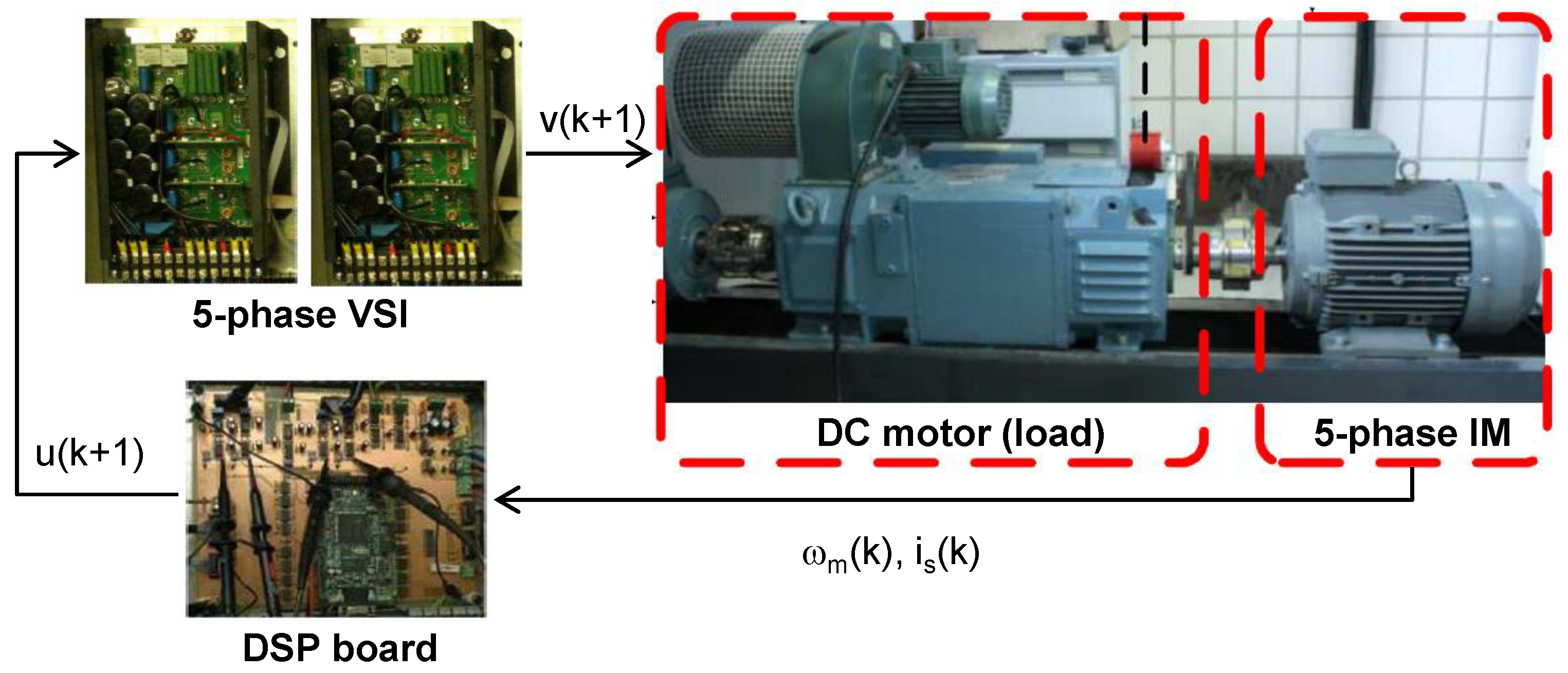
The test rig for experimentation is schematically shown in
Figure 3, it contains a 30-slot symmetrical five-phase IM with three pole pairs made up by distributed windings. The five-phase two-levels VSI is made of two three-phase Semikron SKS22F modules. The DC-link voltage used is
(V). The controllers run on the TMS320F28335 DSP included in a board (MSK28335 Technosoft) which interfaces with the GHM510296R/2500 rotatory encoder. A DC machine is used to emulate the desired load torque in the shaft for the experiments. The IM has the electrical parameters already shown in
Table 1.
As in the simulation section the proposed predictive controller with min-max loss function will be compared against a traditional FCSMPC with two different tunings (
and
). The operating regimes are nominal speed with 4% load (case E1) and nominal speed with 50% load torque (case E2).
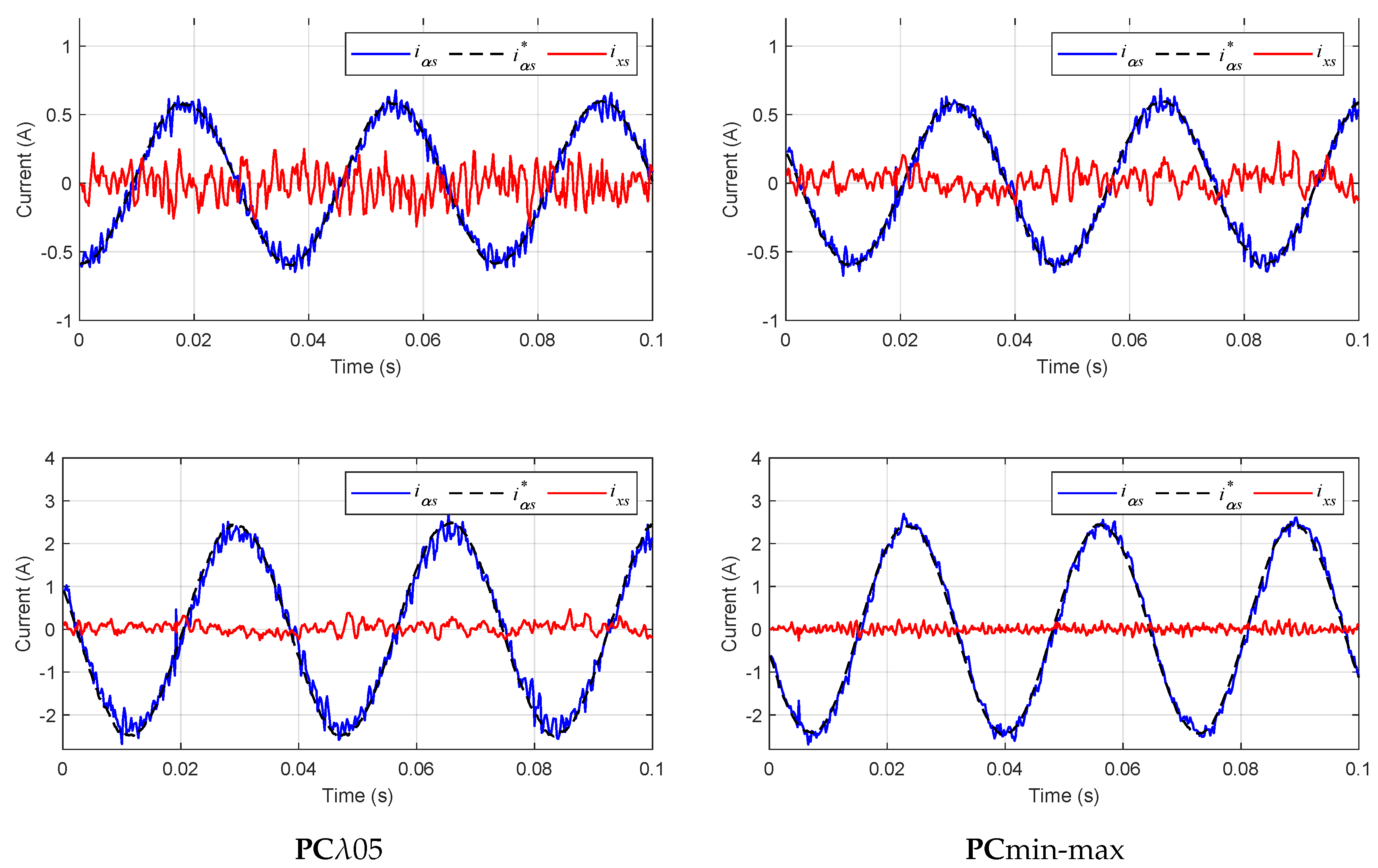
Table 3 shows the RMS control errors. Again, the proposed controller provides low values for the tracking errors in both sub-spaces. The trajectories shown in
Figure 4 allow for further comparison of the proposed controller against the traditional FCSMPC with
for operating points E1 and E2.
The results match very much those already seen in simulation. Please note that a reduction in tracking errors is observed despite the fact that the tuning employed for the traditional FCSMPC is a standard one, found after intensive experimentation (see [
22]). In the case of the proposed min-max loss function, the controller aims at minimizing the largest of errors in either sub-space. This results in trajectories that are smoother as extreme deviations are avoided.
A final set of experiments is performed to show the performance for various speeds.
Table 4 shows the RMS control error for
and
sub-spaces for the proposed min-max PSCC for different speeds and two loads (
(%) and
(%)). Again, it is worth remarking the balanced nature of the results for different operating regimes.
6. Conclusions
It has been shown that a fuzzy decision making scheme can be used for predictive stator current control of multi-phase IM. Similar ideas have been proposed for predictive torque control of conventional (three-phase) IM and PMSM; they have been refined here to provide a means to cope with specific aspects of multi-phase IMs. The computational requirements are low, allowing for its use in real time, as is demonstrated by the experiments using a standard value for the sampling time. It is interesting to see that the proposed controller provides low values for the tracking errors in torque producing () and loss producing () sub-spaces, despite the fact that no tuning is needed.
A good agreement between experimental and simulation results has been found. While watching the results, one must bear in mind that the instantaneous (discrete-time wise) minimization of a loss function does not guarantee a certain result in terms of the trajectories obtained due to the effect of the receding horizon in predictive control. In the case of the proposed min-max loss function, the controller aims at minimizing the largest of errors in either sub-space. This results in trajectories that are observed in the results to be smoother as extreme deviations (in either sub-space) are avoided.


