Bridging the Gap between Automated Manufacturing of Fuel Cell Components and Robotic Assembly of Fuel Cell Stacks


Abstract
1. Introduction
2. Materials and Methods
2.1. Fuel Cell Gaskets
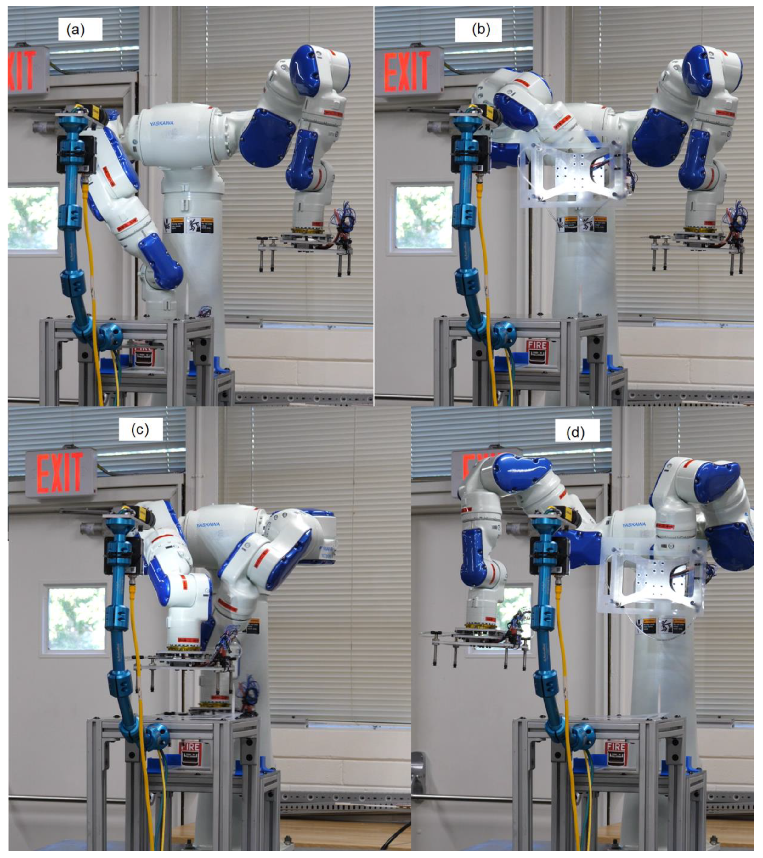
2.2. Tooling
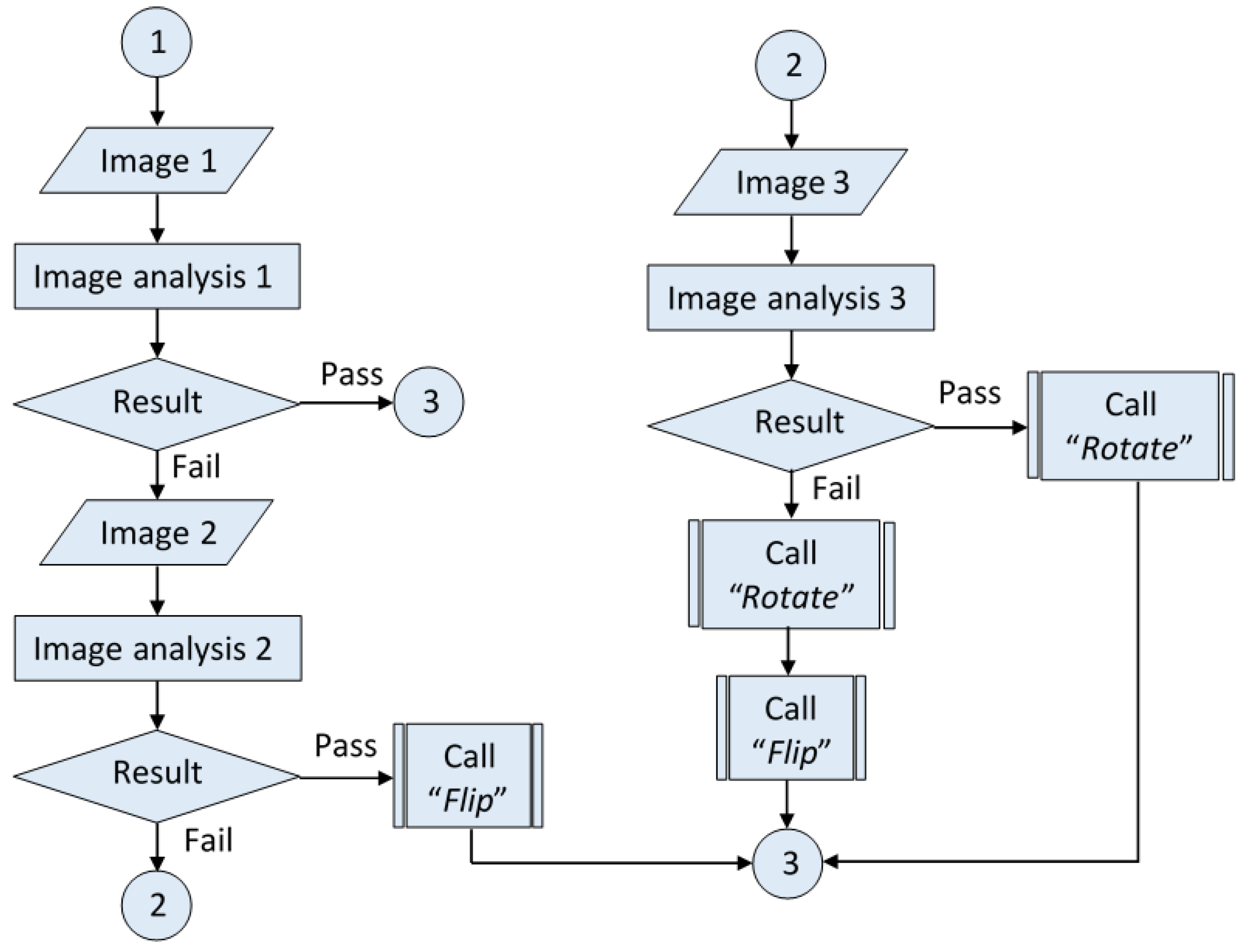
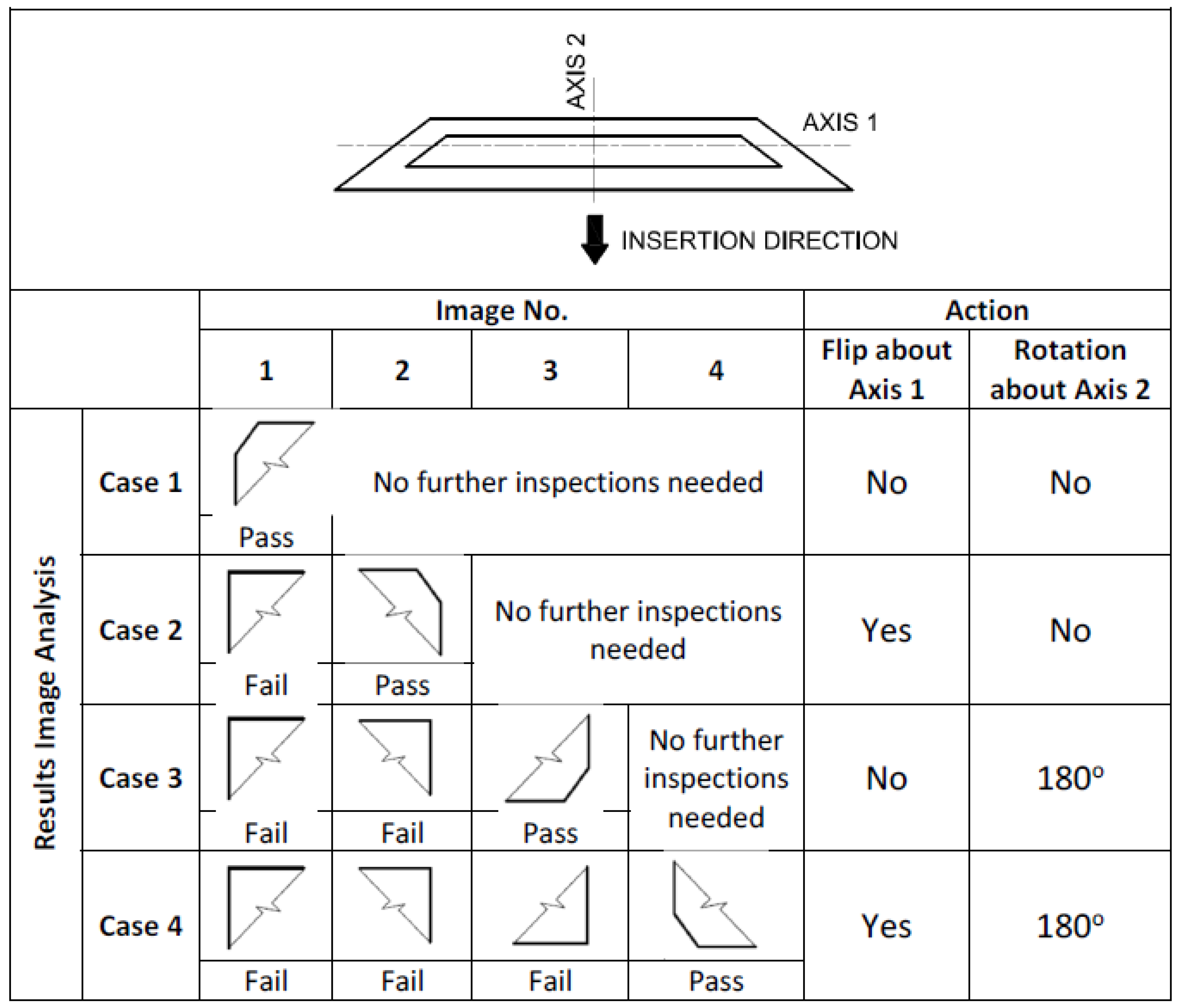
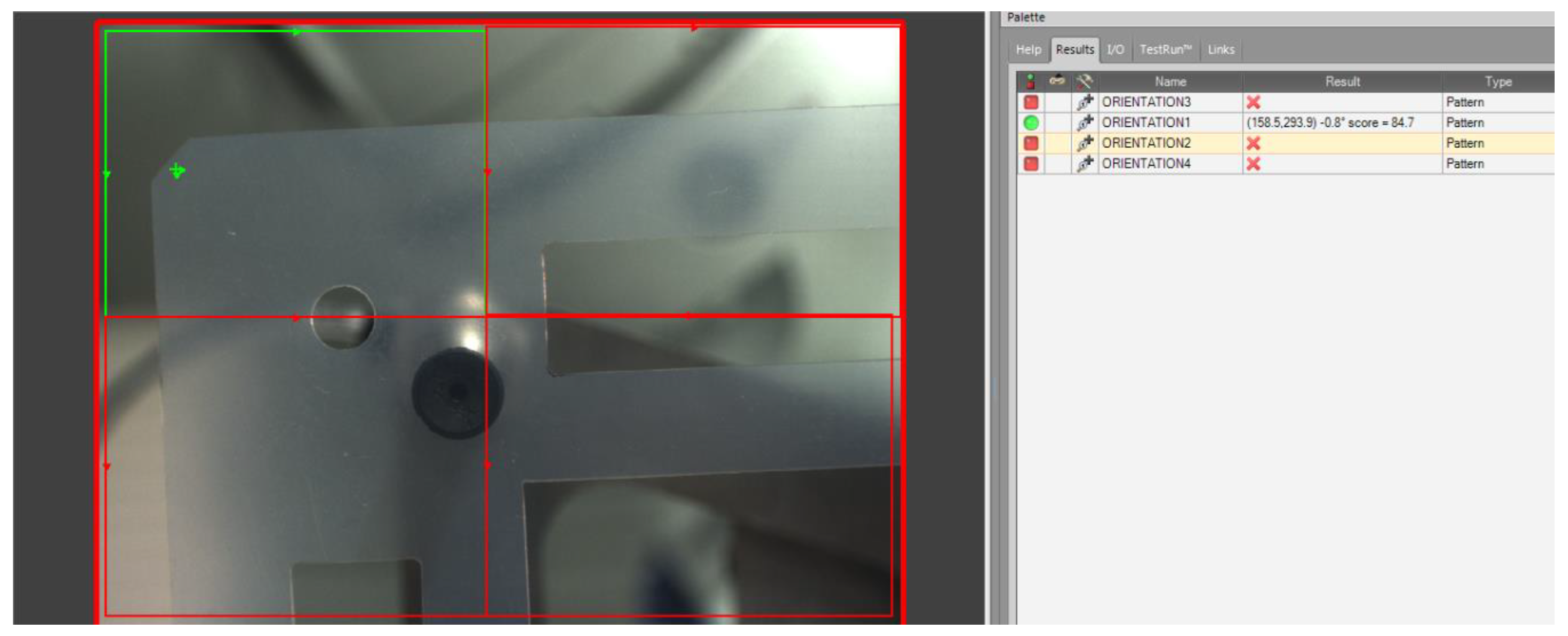
2.3. Algorithm
3. Results
Cycle Time Optimization
4. Conclusions
Supplementary Materials
Author Contributions
Funding
Acknowledgments
Conflicts of Interest
References
- U.S. Department of Energy. Hydrogen and Fuel Cells Program. Fuel Cells. Available online: https://www.hydrogen.energy.gov/fuel_cells.html (accessed on 4 September 2017).
- Global Markets Insight. Fuel Cell Market Size by Application (Stationary, Portable, Transport), by Product (PEMFC, DMFC, SOFC), Industry Analysis Report, Regional Outlook (U.S, Canada, Germany, UK, Japan, South Korea, South Africa, Brazil), Application Potential, Price Trends, Competitive Market Share & Forecast, 2016–2024. Available online: https://www.gminsights.com/industry-analysis/fuel-cell-market (accessed on 5 September 2017).
- Grand View Research. Fuel Cell Market Analysis by Product (PEMFC, PAFC, SOFC, MCFC), By Application (Stationary, Transportation, Portable) and Segment Forecast, 2014–2025. Available online: http://www.grandviewresearch.com/industry-analysis/fuel-cell-market (accessed on 12 September 2017).
- Mehta, V.; Cooper, J.S. Review an Analysis of PEM fuel Cell Design and Manufacturing. J. Power Sources 2003, 114, 32–53. [Google Scholar] [CrossRef]
- Battele Memorial Institute. Manufacturing Cost Analysis of 1, 5, 10 and 25 kW Polymer Electrolyte Membrane (PEM) Fuel Cell Systems for Material Handling Applications; DOE Contract No. DE-EE0005250; U.S. Department of Energy: Washington, DC, USA, 2017.
- Pratt, J.W.; Chan, S.H. Maritime Fuel Cell Generator Project; SANDIA Report, SAND2017-5751; Sandia National Lab: Livermore, CA, USA, 2017. [Google Scholar]
- Benchmarking and Best Practices Center of Excellence. Manufacturing Fuel Cell Manhattan Project; US Gov. Contract No. N00014-08-D-0758; Benchmarking and Best Practices Center of Excellence. Available online: https://www.energy.gov/sites/prod/files/2014/03/f12/manufacturing_fuel_cell_manhattan_project.pdf (accessed on 1 August 2019).
- Battele Memorial Institute. Manufacturing Cost Analysis of 5 and 10 kW Backup Power Applications; DOE Contract No. DE-EE0005250; U.S. Department of Energy: Washington, DC, USA, 2016.
- Pratt, J.W.; Klebanoff, L.E.; Munoz-Ramos, K.; Akhil, A.A.; Curgus, D.B.; Schenkman, B.L. Proton Exchange Membrane Fuel Cells for Electrical Power Generation O-Board Commercial Airplanes; SANDIA Report, SAND2011-3119; Sandia National Lab: Livermore, CA, USA, 2011. [Google Scholar]
- Roth, C.; Bleith, P.; Schwoebel, C.A.; Kaserer, S.; Eicher, J. Importance of Fuel Cell Tests for Stability Assessment—Suitability of Titanium Diboride as an Alternative Support Material. Energies 2014, 7, 3642–3652. [Google Scholar] [CrossRef]
- Han, J.; Charpentier, J.F.; Tang, T. An Energy Management System of a Fuel Cell/Battery Hybrid Boat. Energies 2014, 7, 2799–2820. [Google Scholar] [CrossRef]
- Ma, H.; Cheng, W.; Fung, F.; Hsu, C.; Lin, C. Compact Design of 10 kW Proton Exchange Membrane Fuel Cell Stack Systems with Microcontroller Units. Energies 2014, 7, 2498–2514. [Google Scholar] [CrossRef]
- Hwang, K.; Kim, J.H.; Kim, S.Y.; Byun, H. Preparation of Polybenzimidazole-Based Membranes and Their Potential Applications in the Fuel Cell System. Energies 2014, 7, 1721–1732. [Google Scholar] [CrossRef]
- San Martin, I.; Ursua, A.; Sanchis, P. Modelling of PEM Fuel Cell Performance: Steady-State and Dynamic Experimental Validation. Energies 2014, 7, 670–700. [Google Scholar] [CrossRef]
- Chang, L.Y.; Chen, H.C. Linearization and Input-Output Decoupling for Nonlinear Control of Proton Exchange Membrane Fuel Cells. Energies 2014, 7, 591–606. [Google Scholar] [CrossRef]
- Kulikovsky, A. Polarization Curve of a Non-Uniformly Aged PEM Fuel Cell. Energies 2014, 7, 351–364. [Google Scholar] [CrossRef]
- Liu, J.; Yuan, Y.; Bashir, S. Functionalization of Aligned Carbon Nanotubes to Enhance the Performance of Fuel Cell. Energies 2013, 6, 6476–6486. [Google Scholar] [CrossRef]
- Chen, Y.S.; Lin, S.M.; Hong, B.S. Experimental Study on a Passive Fuel Cell/Battery Hybrid Power System. Energies 2013, 6, 6413–6422. [Google Scholar] [CrossRef]
- Tavcar, G.; Katrasnik, T. An Innovative Hybrid 3D Analytic-Numerical Approach for System Level Modelling of PEM Fuel Cells. Energies 2013, 6, 5426–5485. [Google Scholar] [CrossRef]
- Alink, R.; Gerteisen, D. Modeling the Liquid Water Transport in the Gas Diffusion Layer for Polymer Electrolyte Membrane Fuel Cells Using a Water Path Network. Energies 2013, 6, 4508–4530. [Google Scholar] [CrossRef]
- Wan, Z.; Chang, H.; Shu, S.; Wang, Y.; Tang, H. A Review on Cold Start of Proton Exchange Membrane Fuel Cells. Energies 2014, 7, 3179–3203. [Google Scholar] [CrossRef]
- Bozzini, B.; Bocchetta, P.; Gianocelli, A. Coelectrodeposition of Ternary Mn-Oxide/Polypyrrole Composites for ORR Electrocatalysts: A Study Based on Micro-X-ray Absorption Spectroscopy and X-ray Fluorescence Mapping. Energies 2015, 8, 8145–8164. [Google Scholar] [CrossRef]
- Stassi, A.; Gatto, I.; Sacca, A.; Baglio, V.; Arico, A.S. Enhancement of Oxygen Reduction and Mitigation of Ionomer Dry-Out Using Insoluble Heteropoly Acids in Intermediate Temperature Polymer-Electrolyte Membrane Fuel Cells. Energies 2015, 8, 7805–7817. [Google Scholar] [CrossRef]
- Jeong, S.K.; Lee, J.S.; Woo, S.H.; Seo, J.A.; Min, B.R. Characterization of Anion Exchange Membrane Containing Epoxy Ring and C–Cl Bond Quaternized by Various Amine Groups for Application in Fuel Cells. Energies 2015, 8, 7084–7099. [Google Scholar] [CrossRef]
- Balzarotti, R.; Latorrata, S.; Stampino, P.G.; Cristiani, C.; Dotelli, G. Development and Characterization of Non-Conventional Micro-Porous Layers for PEM Fuel Cells. Energies 2015, 8, 7070–7083. [Google Scholar] [CrossRef]
- Kiatkittkul, P.; Nohira, T.; Hagiwara, R. Nonhumidified Fuel Cells Using N-Ethyl-N-methyl-pyrrolidinium Fluorohydrogenate Ionic Liquid-poly (Vinylidene Fluoride-Hexafluoropropylene) Composite Membranes. Energies 2015, 8, 6202–6214. [Google Scholar] [CrossRef]
- Choi, J.S.; Sohn, J.Y.; Shin, J. A Comparative Study on EB-Radiation Deterioration of Nafion Membrane in Water and Isopropanol Solvents. Energies 2015, 8, 5370–5380. [Google Scholar] [CrossRef]
- Vinh, N.D.; Kim, H.M. Comparison of Numerical and Experimental Studies for Flow-Field Optimization Based on Under-Rib Convection in Polymer Electrolyte Membrane Fuel Cells. Energies 2016, 9, 844. [Google Scholar] [CrossRef]
- Endo, N.; Ogawa, Y.; Ukai, K.; Kakihana, Y.; Higa, M. DMFC Performance of Polymer Electrolyte Membranes Prepared from a Graft-Copolymer Consisting of a Polysulfone Main Chain and Styrene Sulfonic Acid Side Chains. Energies 2016, 9, 658. [Google Scholar] [CrossRef]
- Cheng, S.; Xu, L.; Li, J.; Fang, C.; Hu, J.; Ouyang, M. Development of a PEM Fuel Cell City Bus with a Hierarchical Control System. Energies 2016, 9, 417. [Google Scholar] [CrossRef]
- Lee, H.S.; Cho, C.W.; Seo, J.H.; Lee, M.Y. Cooling Performance Characteristics of the Stack Thermal Management System for Fuel Cell Electric Vehicles under Actual Driving Conditions. Energies 2016, 9, 320. [Google Scholar] [CrossRef]
- Sgambetterra, M.; Brutti, S.; Allodi, V.; Mariotto, G.; Panero, S.; Navarra, M.A. Critical Filler Concentration in Sulfated Titania-Added Nafion™ Membranes for Fuel Cell Applications. Energies 2016, 9, 272. [Google Scholar] [CrossRef]
- Jang, H.; Sutradhar, S.C.; Yoo, J.; Ha, J.; Pyo, J.; Lee, C.; Ryu, T.; Kim, W. Synthesis and Characterization of Sulfonated Poly (Phenylene) Containing a Non-Planar Structure and Dibenzoyl Groups. Energies 2016, 9, 115. [Google Scholar] [CrossRef]
- Wang, C.; Wang, S.; Peng, L.; Zhang, J.; Shao, Z.; Huang, J.; Sun, C.; Ouyang, M.; He, X. Recent Progress on the Key Materials and Components for Proton Exchange Membrane Fuel Cells in Vehicle Applications. Energies 2016, 9, 603. [Google Scholar] [CrossRef]
- Qin, Y.; Wang, X.; Chen, R.; Shangguan, X. Water Transport and Removal in PEMFC Gas Flow Channel with Various Water Droplet Locations and Channel Surface Wettability. Energies 2018, 11, 880. [Google Scholar] [CrossRef]
- Byun, S.J.; Wang, Z.H.; Son, J.; Kwak, D.K.; Kwon, Y.C. Experimental Study on Improvement of Performance by Wave Form Cathode Channels in a PEM Fuel Cell. Energies 2018, 11, 319. [Google Scholar] [CrossRef]
- Latoratta, S.; Stampino, P.G.; Cristiani, C.; Dotelli, G. Performance Evaluation and Durability Enhancement of FEP-Based Gas Diffusion Media for PEM Fuel Cells. Energies 2017, 10, 2063. [Google Scholar] [CrossRef]
- Mao, L.; Davies, B.; Jackson, L. Application of the Sensor Selection Approach in Polymer Electrolyte Membrane Fuel Cell Prognostics and Health Management. Energies 2017, 10, 1511. [Google Scholar] [CrossRef]
- U.S. Department of Energy. Roadmap on Manufacturing R&D for the Hydrogen Economy. Available online: https://www.hydrogen.energy.gov/pdfs/roadmap_manufacturing_hydrogen_economy.pdf (accessed on 4 September 2017).
- Gurau, V.; Fowler, D.; Cox, D. Robotic Technologies for Proton Exchange Membrane Fuel Cell Assembly. In Proton Exchange Membrane Fuel Cells; Taner, T., Ed.; InTech: London, UK, 2018; pp. 21–34. ISBN 978-1-78923-066-6. [Google Scholar]
- Gurau, V.; Armstrong-Koch, T. Further Improvements of an End-Effector for Robotic Assembly of Polymer Electrolyte Membrane Fuel Cells. Energies 2015, 8, 9452–9463. [Google Scholar] [CrossRef]
- Williams, M.; Tignor, K.; Sigler, L.; Rajagopal, C.; Gurau, V. Robotic Arm for Automated Assembly of Proton Exchange Membrane Fuel Cell Stacks. J. Fuel Cell Sci. Technol. 2014, 11, 054501. [Google Scholar] [CrossRef]
- Laskowski, C.M. Design-for-Manufacture Guidelines for Automated Assembly of Proton Exchange Membrane (PEM) Fuel Cell Stacks. Ph.D. Thesis, Rensselaer Polytechnic Institute, Troy, NY, USA, 2011. [Google Scholar]
- Laskovski, C.; Derby, S. Fuel Cell ASAP: Two Iterations of an Automated Stack Assembly Process and Ramifications for Fuel Cell Design-For-Manufacture. J. Fuel Cell Sci. Technol. 2011, 8, 031004. [Google Scholar] [CrossRef]
- KUKARobotGroup. The Production of Proton Exchange Membrane Fuel Cells with a KUKA Robot. Available online: https://www.youtube.com/watch?v=E-vcRR4mC6w (accessed on 14 September 2017).
- Konold, P.; Muminovic, A.; Wehreim, M. Assembly of Fuel Cells and Stacks with Robots. In Research and Education in Robotics: EUROBOT 2008; Gottscheber, A., Enderle, S., Obdrzalek, D., Eds.; Springer: Berlin/Heidelberg, Germany, 2009; pp. 168–179. [Google Scholar]
- Zentrum für BrennstoffzellenTechnik. Fuel Cell Manufacturing Plant/Automatisierte Brennstoffzellenmontage am ZBT. Available online: https://www.youtube.com/watch?v=KhrcHO_qw80 (accessed on 14 September 2017).
- Boothroyd, G.; Dewhurst, P.; Knight, W.A. Product Design for Manufacture and Assembly, 3rd ed.; CRC Press: Boca Raton, FL, USA, 2011. [Google Scholar]
- Gurau, V. Robotic Fuel Cell Assembly System. US Patent 2015/0158179 A1, 11 June 2015. [Google Scholar]
- Fowler, D. Hydrogen Fuel Cell Gasket Handling and Alignment with Machine Vision Integrated Dual Arm Robot. Master’s Thesis, Georgia Southern University, Statesboro, GA, USA, 2019. [Google Scholar]


| Operation | Time (s) | Average Cycle Time for Transferring One Gasket (s) |
|---|---|---|
| Pick up gasket from the bin and bring it in front of camera | 7.45 | 14.35 |
| Image analysis and reorientation Case 1 | 3.00 | |
| Image analysis and reorientation Case 2 | 9.30 | |
| Image analysis and reorientation Case 3 | 6.30 | |
| Image analysis and reorientation Case 4 | 13.0 | |
| Insert gasket in presenter and withdraw the hand | 6.30 |
| Operator | Run 1 | Run 2 | Run 3 | |||
|---|---|---|---|---|---|---|
| Time (m:s) | Errors | Time (m:s) | Errors | Time (m:s) | Errors | |
| 1 | 1:46.88 | 2 | 1:43.99 | 0 | 1:43.76 | 0 |
| 2 | 1:24.23 | 0 | 1:19.12 | 0 | 1:18.62 | 0 |
| 3 | 1:39.30 | 0 | 1:32.12 | 0 | 1:25.63 | 0 |
| 4 | 1:34.84 | 0 | 1:34.04 | 0 | 1:26.84 | 0 |
| 5 | 1:10.27 | 0 | 1:08.95 | 0 | 1:04.96 | 0 |
© 2019 by the authors. Licensee MDPI, Basel, Switzerland. This article is an open access article distributed under the terms and conditions of the Creative Commons Attribution (CC BY) license (http://creativecommons.org/licenses/by/4.0/).
Share and Cite
Fowler, D.; Gurau, V.; Cox, D. Bridging the Gap between Automated Manufacturing of Fuel Cell Components and Robotic Assembly of Fuel Cell Stacks. Energies 2019, 12, 3604. https://doi.org/10.3390/en12193604
Fowler D, Gurau V, Cox D. Bridging the Gap between Automated Manufacturing of Fuel Cell Components and Robotic Assembly of Fuel Cell Stacks. Energies. 2019; 12(19):3604. https://doi.org/10.3390/en12193604
Chicago/Turabian StyleFowler, Devin, Vladimir Gurau, and Daniel Cox. 2019. "Bridging the Gap between Automated Manufacturing of Fuel Cell Components and Robotic Assembly of Fuel Cell Stacks" Energies 12, no. 19: 3604. https://doi.org/10.3390/en12193604
APA StyleFowler, D., Gurau, V., & Cox, D. (2019). Bridging the Gap between Automated Manufacturing of Fuel Cell Components and Robotic Assembly of Fuel Cell Stacks. Energies, 12(19), 3604. https://doi.org/10.3390/en12193604